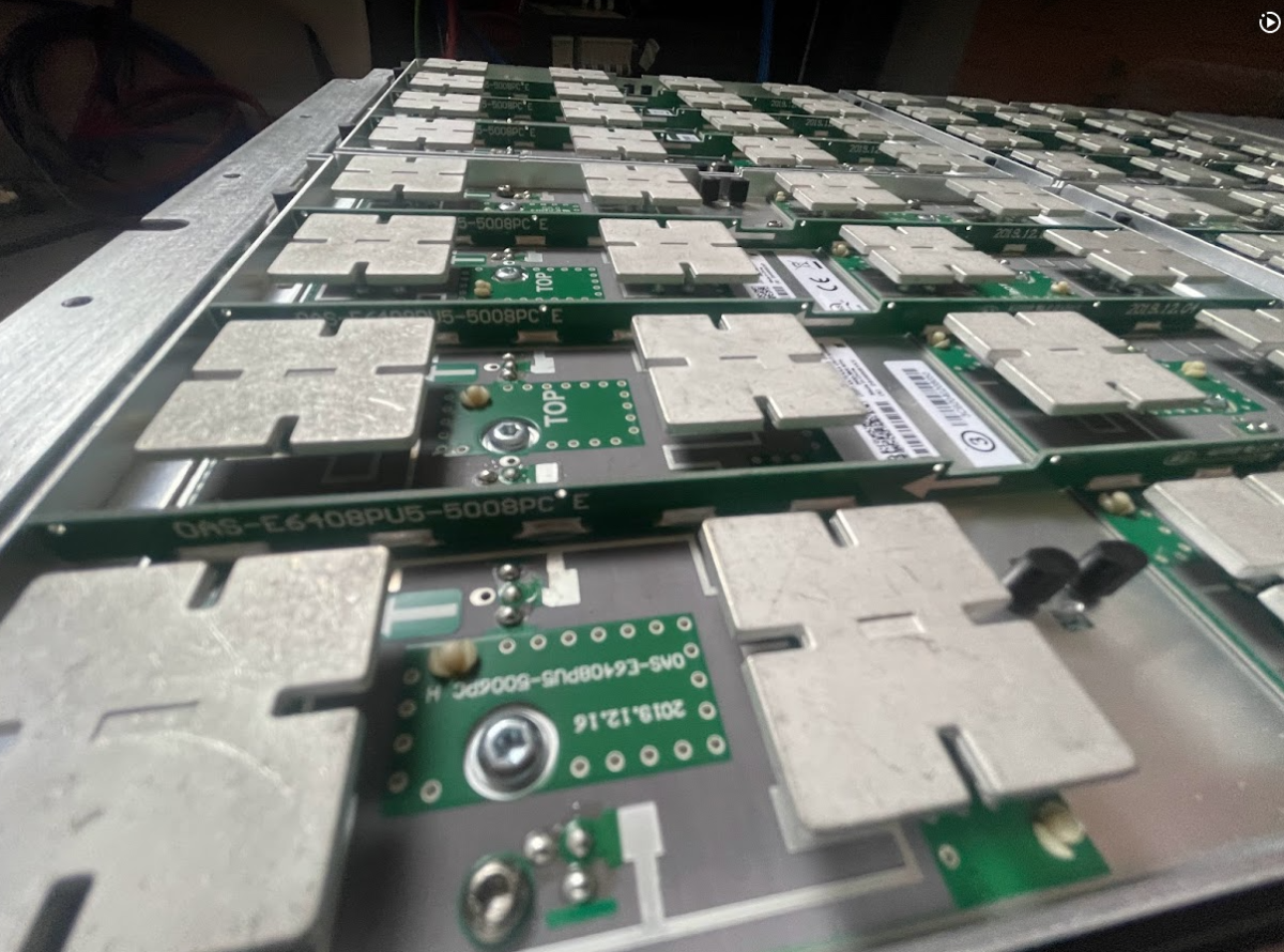
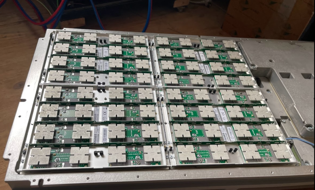
Last year I purchased a cheap second hand Huawei macro base station – there’s lots of these on the market at the moment due to the fact they’re being replaced in many countries.
I’m using it in my lab environment, and as such the config I’ve got is very “bare bones” and basic. Keep in mind if you’re looking to deploy a Macro eNodeB in production, you may need more than just a blog post to get everything tuned and functioning properly…
In this post we’ll cover setting up a Huawei BTS3900 eNodeB from scratch, using the MML interface, without relying on the U2020 management tool.
Obviously the details I setup (IP Addressing, PLMN and RF parameters) are going to be different to what you’re configuring, so keep that in mind, where I’ve got my MME Addresses, site IDs, TACs, IP Addresses, RFUs, etc, you’ll need to substitute your own values.
A word on Cabinets
Typically these eNodeBs are shipped in cabinets, that contain the power supplies, alarm / environmental monitoring, power distribution, etc.
Early on in the setup process we’ll be setting the cabinet types we’ve got, and then later on we’ll tell the system what we have installed in which slots.
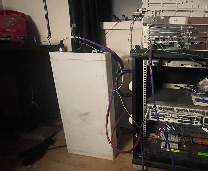
This is fine if you have a cabinet and know the type, but in my case at least I don’t have a cabinet manufactured by Huawei, just a rack with some kit mounted in it.
This is OK, but it leads to a few gotchas I need to add a cabinet (even though it doesn’t physically exist) and when I setup my RRUs I need to define what cabinet, slot and subrack it’s in, even though it isn’t in any. Keep this in mind as we go along and define the position of the equipment, that if you’re not using a real-world cabinet, the values mean nothing, but need to be kept consistent.
The Basics
Before we get started, familiarise yourself with the Huawei MML we’ll use for configuring the unit, and log into the Web UI and bring up an MML shell.
To begin we’ll need to setup the basics, by disabling DHCP and setting an local IP Address for the unit.
 SET DHCPSW: SWITCH=DISABLE;
 SET LOCALIP: IP="192.168.5.234", MASK="255.255.248.0";
Obviously your IP address details will be different.
Next we’ll add an eNodeB function, the LMPT / UMPT can have multiple functions and multiple eNodeBs hosted on the same hardware, but in our case we’re just going to configure one:
 ADD ENODEBFUNCTION: eNodeBFunctionName="LTE", ApplicationRef=1, eNodeBId=9527;
 SET NE: NENAME="HUAWEI", LOCATION="NewSite", DID="NewSite12345", SITENAME="NewSite1", USERLABEL="NewInitSite";
 ADD LOCATION: LOCATIONNAME="NewSite", GCDF=Degree, LATITUDEDEGFORMAT=0, LONGITUDEDEGFORMAT=0;
Again, your eNodeB ID, location, site name, etc, are all going to be different, as will your location.
Next we’ll set the system to maintenance mode (MNTMODE), so we can make changes on the fly (this takes the eNB off the air, but we’re already off the air), you’ll need to adjust the start and end times to reflect the current time for the start time, and end time to be after you’re done setting all this up.
SET MNTMODE: MNTMode=INSTALL, ST=2013&09&20&15&00&00, ET=2013&09&25&15&00&00, MMSetRemark="NewSite Install";
Next we’ll set the operator details, this is the PLMN of the eNodeB, and create a new tracking area.
 ADD CNOPERATOR: CnOperatorId=0, CnOperatorName="NickTest", CnOperatorType=CNOPERATOR_PRIMARY, Mcc="001", Mnc="01";
 ADD CNOPERATORTA: TrackingAreaId=0, CnOperatorId=0, Tac=1;
Next we’ll be setting and populating the cabinets I mentioned earlier. I’ll be telling the unit it’s inside a APM30 (Cabinet 0), and in Cabinet Number 0, Subrack 0, is a BBU3900.
 //To modify the cabinet type, run the following command:
 ADD CABINET:CN=0,TYPE=APM30;
 //Add a BBU3900 subrack, run the following command:
 ADD SUBRACK:CN=0,SRN=0,TYPE=BBU3900;
 //To configure boards and RF datas, run the following commands:
And inside the BBU3900 there’s some cards of course, and each card has as slot, as per the drawing below.

In my environment I’ve got a LMPT in slot 7, and a LBBP in Slot 3. There’s a fan and a UPEU too, so:
We’ll add a board in Slot No. 7, of type LMPT,
We’ll add a board in Slot No. 3, of type LBBP working on FDD,
We’ll add a fan board in Slot No. 16, and a UPEU in Slot No. 18.
 ADD BRD:SN=7,BT=LMPT;
 ADD BRD:CN=0,SRN=0,SN=3,BT=LBBP,WM=TDD;
 ADD BRD:CN=0,SRN=0,SN=16,BT=FAN;
 ADD BRD:CN=0,SRN=0,SN=18,BT=UPEU;
Huawei publish design guides for which cards should be in which slots, the general rule is that your LMPT / UMPT card goes in Slot 7, with your BBP cards (UBBP or LBBP) in slots 3, then 2, then 1, then 0. Fans and UPEUs can only go in the slots designed to fit them, so that makes it a bit easier.
Next we’ll need to setup our RRUs, for this we’ll need to setup an RRU chain, which is the Huawei term for the CPRI links and add an RRU into it:
ADD RRUCHAIN:RCN=10,TT=CHAIN,BM=COLD,HSRN=70,HSN=0,HPN=0;

ADD RRU:CN=0,SRN=60,SN=0,TP=BRANCH,RCN=10,PS=0,RT=MPMU,RS=TDL,RXNUM=0,TXNUM=0;
With our RRU chains defined, we’ll need to setup our transport network to get the traffic back to the S-GW / MME:
SET ETHPORT: SN=7, SBT=BASE_BOARD, PA=COPPER, SPEED=AUTO, DUPLEX=AUTO;
ADD DEVIP: SN=7, SBT=BASE_BOARD, PT=ETH, PN=0, IP="10.10.10.67", MASK="255.255.255.0";
ADD IPRT: RTIDX=0, SN=7, SBT=BASE_BOARD, DSTIP="10.166.1.251", DSTMASK="255.255.255.255", RTTYPE=NEXTHOP, NEXTHOP="10.10.10.1";
ADD IPRT: RTIDX=1, SN=7, SBT=BASE_BOARD, DSTIP="10.4.3.3", DSTMASK="255.255.255.255", RTTYPE=NEXTHOP, NEXTHOP="10.10.10.1";
ADD IPRT: RTIDX=2, SN=7, SBT=BASE_BOARD, DSTIP="10.3.3.3", DSTMASK="255.255.255.255", RTTYPE=NEXTHOP, NEXTHOP="10.10.10.1";
ADD IPRT: RTIDX=3, SN=7, SBT=BASE_BOARD, DSTIP="10.60.60.60", DSTMASK="255.255.255.255", RTTYPE=NEXTHOP, NEXTHOP="10.10.10.1";
ADD OMCH: IP="10.10.10.67", MASK="255.255.255.0", PEERIP="10.166.1.251", PEERMASK="255.255.255.255", BEAR=IPV4, BRT=YES, RTIDX=0, BINDSECONDARYRT=NO, CHECKTYPE=NONE;
ADD VLANMAP: NEXTHOPIP="10.10.10.1", MASK="255.255.248.0", VLANMODE=SINGLEVLAN, VLANID=3721, SETPRIO=DISABLE;
ADD SCTPTEMPLATE: SCTPTEMPLATEID=0, SWITCHBACKFLAG=ENABLE;
ADD SCTPHOST: SCTPHOSTID=0, IPVERSION=IPv4, SIGIP1V4="10.10.10.67", SIGIP1SECSWITCH=DISABLE, SIGIP2SECSWITCH=DISABLE, PN=2000, SCTPTEMPLATEID=0;
ADD SCTPPEER: SCTPPEERID=0, IPVERSION=IPv4, SIGIP1V4="10.3.3.3", SIGIP1SECSWITCH=DISABLE, SIGIP2SECSWITCH=DISABLE, PN=2000;
ADD USERPLANEHOST: UPHOSTID=0, IPVERSION=IPv4, LOCIPV4="10.10.10.67", IPSECSWITCH=DISABLE;
ADD EPGROUP: EPGROUPID=0;
ADD SCTPHOST2EPGRP: EPGROUPID=0, SCTPHOSTID=0;
ADD SCTPPEER2EPGRP: EPGROUPID=0, SCTPPEERID=0;
ADD UPHOST2EPGRP: EPGROUPID=0, UPHOSTID=0;
ADD S1: S1Id=0, CnOperatorId=0, EpGroupCfgFlag=CP_UP_CFG, CpEpGroupId=0, UpEpGroupId=0;
We’ll need clocking and time as well, we’ll use NTP and GPS:
SET TIMESRC: TIMESRC=NTP;
ADD NTPC: MODE=IPV4, IP="10.166.1.251", PORT=123, SYNCCYCLE=60, AUTHMODE=PLAIN;
SET MASTERNTPS: MODE=IPV4, IP="10.166.1.251";
SET TZ: ZONET=GMT+0800, DST=NO;

ADD GPS: SRN=0, SN=7;
SET CLKMODE: MODE=MANUAL, CLKSRC=GPS, SRCNO=0;
SET CLKSYNCMODE:CLKSYNCMODE=TIME;
Next we’ll need to define a sector, sector equipment & cell, then link it to a sector equipment group:
ADD SECTOR:SECTORID=0,ANTNUM=2,ANT1CN=0,ANT1SRN=60,ANT1SN=255, ANT1N=R0A,ANT2CN=0,ANT2SRN=60,ANT2SN=255,ANT2N=R0B,CREATESECTOREQM=FALSE;

ADD SECTOREQM:SECTOREQMID=0,SECTORID=0,ANTNUM=2,ANT1CN=0, ANT1SRN=60,ANT1SN=255,ANT1N=R0A,ANTTYPE1=RXTX_MODE,ANT2CN=0,ANT2SRN=60,ANT2SN=255,ANT2N=R0B,ANTTYPE2=RXTX_MODE;

ADD CELL:LOCALCELLID=1,CELLNAME="CELL1",FREQBAND=41,ULEARFCNCFGIND=NOT_CFG,DLEARFCN=40340,ULBANDWIDTH=CELL_BW_N100,DLBANDWIDTH=CELL_BW_N100,CELLID=1,PHYCELLID=1,FDDTDDIND=CELL_TDD,SUBFRAMEASSIGNMENT=SA2,SPECIALSUBFRAMEPATTERNS=SSP5,ROOTSEQUENCEIDX=0,CUSTOMIZEDBANDWIDTHCFGIND=NOT_CFG,EMERGENCYAREAIDCFGIND=NOT_CFG,UEPOWERMAXCFGIND=NOT_CFG,MULTIRRUCELLFLAG=BOOLEAN_TRUE,MULTIRRUCELLMODE=MPRU_AGGREGATION, CPRICOMPRESSION=NORMAL_COMPRESSION,TXRXMODE=2T2R;

ADD EUSECTOREQMGROUP:LOCALCELLID=1,SECTOREQMGROUPID=1;
ADD EUSECTOREQMID2GROUP:LOCALCELLID=1,SECTOREQMGROUPID=1, SECTOREQMID=0;
Alright, now we can activate it:
//Modify the reference signal power.
MOD PDSCHCFG: LocalCellId=1, ReferenceSignalPwr=-81;

//Add an operator for the cell.
ADD CELLOP: LocalCellId=0, TrackingAreaId=0;

//Activate the cell.
ACT CELL: LocalCellId=1;
And lastly we can define some neighboring cells:
//Configure neighboring cells.
ADD EUTRANINTERNFREQ: LocalCellId=1, DlEarfcn=3100, UlEarfcnCfgInd=NOT_CFG, CellReselPriorityCfgInd=NOT_CFG, SpeedDependSPCfgInd=NOT_CFG, MeasBandWidth=MBW100, PmaxCfgInd=NOT_CFG, QqualMinCfgInd=NOT_CFG;
ADD EUTRANEXTERNALCELL: Mcc="460", Mnc="02", eNodeBId=236, CellId=0, DlEarfcn=3100, UlEarfcnCfgInd=NOT_CFG, PhyCellId=236, Tac=33;
ADD EUTRANINTERFREQNCELL: LocalCellId=1, Mcc="460", Mnc="02", eNodeBId=236, CellId=0;

