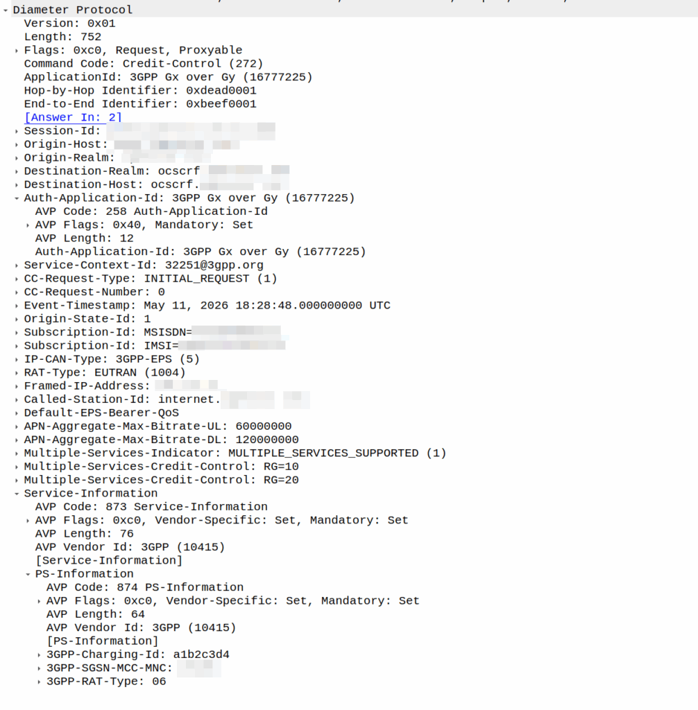
I was recently asked by a potential customer if we supported Gx over Gy.
I’d never heard of this before, so I gave my standard “If it’s in the spec we should support it, but I’ll check” answer, and got them to send me a PCAP, which I’ve got.
This is weird.
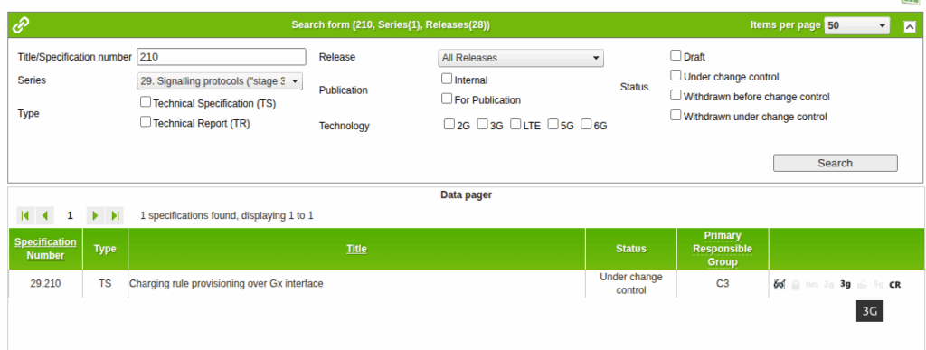
So for starers, Protocoldex has nothing for this application ID (16777225), even though it has all the LTE diameter specs.
The last version was from 2006, in 3GPP release 6, which is two years before LTE was standardized in Release 8. The word LTE does not appear in the doc or in the metadata tags.
It speaks of TPF (Traffic Plane Function) and TPF (Charging Rules Function).
LTE is “Long Term Evolution” – In later releases this draft TPF would evolve into the PGW (before the PGW-C / PGW-U divorce) and the TPF would go on to become the PCRF (and save spring break).
Reading through these early specs is like looking at Homo Eructs (get your mind out of the gutter) and knowing it evolves into Homo Sapiens.
So what does Gx over Gy do? Well, the concept is pretty straightforward, rather than needing a Sy interface between the PCRF and OCS, you can provision policy rules from the OCS, rather than on the PCRF.
So what network functions should implement this standard? Well, the P-GW specs do not reference this as something that’s included in the P-GW, nor is it in the GGSN – This was a “gooch” spec between the hypothetical standards land and real world implementations.
So will we be implementing it? Probably not. But an interesting bit of archaeology and a look through the genealogy of 3GPP.
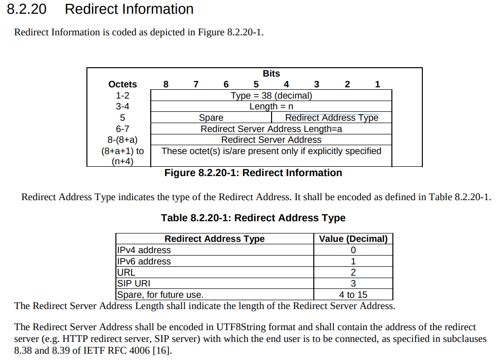
There’s a cool feature in PFCP that allows you to redirect traffic, which I’ve written about before.
But there’s a funky thing that’s left me scratching my head, in the Redirect information IE, you can set a SIP URI.
Snippet from TS 3GPP TS 29.244
That’d be great and all, but PFCP is all about packets not about calls.
So what’s the deal?
Had I uncovered some Machiavellian plot to move channel-associated-signaling onto PFCP instead of TDM links as God intended?
Well, no…
The Redirect Information in PFCP comes from the Redirect Information in Diameter, that’s how your OCS can tell your SMF or your PGW-C (or your TAS) – hey this session is all out of usage, and should be redirected.
Of course, PFCP is just all about packets, but Diameter has a foot in both camps, Gy and Ro are both on Diameter.
PFCP includes a “Redirect Information” IE, which if set, allows you to change the forwarding action in PFCP to Redirect traffic.
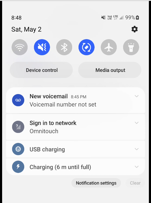
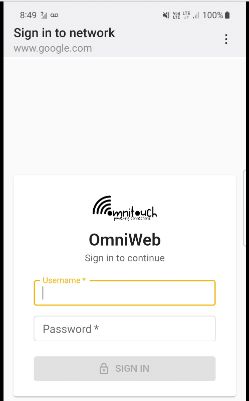
We use this for walled garden redirects, when the OCS reports credit exhausted to the PGW-C, the PGW-C can tell the UPF (PGW-U) that all the traffic from a given subscriber should be redirected to a captive portal / walled garden, like a “Topup Now Page” you’d be used to seeing on Airport WiFi.
“Sign in to network” prompt presented on Cellular
Here’s what the spec says:
8.37. Redirect-Server AVP The Redirect-Server AVP (AVP Code 434) is of type Grouped and contains the address information of the redirect server (e.g., HTTP redirect server, SIP Server) with which the end user is to be connected when the account cannot cover the service cost. It MUST be present when the Final-Unit-Action AVP is set to REDIRECT. It is defined as follows (per the grouped-avp-def of RFC 3588 [DIAMBASE]): Redirect-Server ::= < AVP Header: 434 > { Redirect-Address-Type } { Redirect-Server-Address }
So how does this work in practice?
Once upon a time, you’d just intercept all HTTP request and serve your own content, but it’s not 2005 on Starbucks WiFi anymore, and SSL is everywhere.
Luckily this is a (mostly) solved problem, Apple has “Captive Network Assistant” that probes http://captive.apple.com/hotspot-detect.html and checks for a specific response, Google’s Android has http://connectivitycheck.gstatic.com/generate_204 and does the same thing.
But before I can tell you what we do, I’ll show you what we’re not doing before we do the doing so you can see what the do does by looking at what happens when we don’t – Clear?
Before we send any Session Modification Request with redirect I can do a DNS lookup, here’s an example from our test jig that goes to Facebook:
A Record lookup for facebook.com resolving to 57.145.8.1
This is just a regular A record DNS query wrapped up in GTP-U as it’d look from a eNB/gNB/SGW that gets an answer back also in GTP-U.
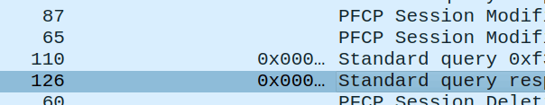
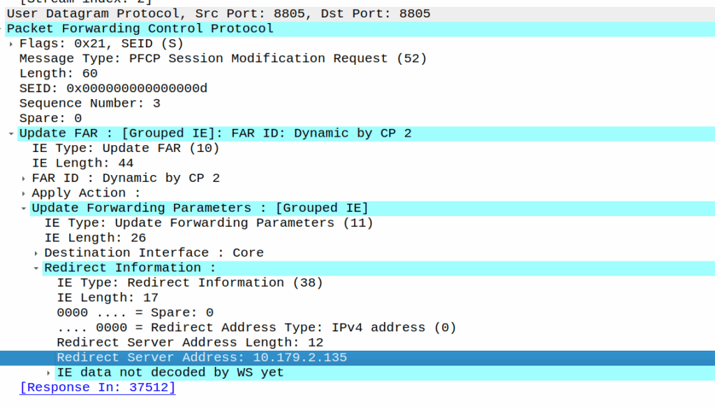
As we’ve already got a session up in our case, the SMF or PGW-C we sends the PFCP Session Modification Request I shared in the screenshot earlier to the UPF.
The Redirect Server Address in the Redirect Information IE in PFCP
We do a few things on the UPF at this point, the first, is that we block forwarding access to all IPs except 10.179.2.135 (The redirect server in the screenshot), and we steal / intercept all DNS queries.
This means if you query facebook.com after the Redirect Information is in place, you get back an A-Record answer for facebook.com but it’s telling you Facebook lives on our redirect server.
We’ve got a whitelist on our UPF for certain domains, so if we’re sending you to a self-signup page, you’re going to need to be able to hit our payment processors portals (Stripe, Paypal, etc), so we need to allow their domains, but we don’t know their IPs, so instead we do server side DNS lookups (via our DNS servers before you sneaky kids get any other ideas) for the whitelsited domains, and if it’s on our DNS whitelist, we allow resolution to those domains and allow access to those IPs returned in the DNS response.
In my lab I’m redirecting HTTP traffic to a management server
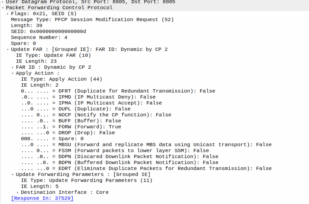
Turning it off just involves sending another PFCP Session Modification Request but without the redirect information.
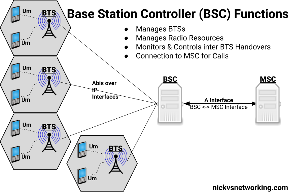
This is an idea I’ve been kicking around for a little while – A single GSM TRX being broadcast across multiple cell sites.
Generally in GSM land, a “TRX” is a cell or a sector – but it doesn’t need to be. Later in GSM features like antenna diversity allow the same signal to be broadcast out multiple ports and received on multiple ports, and these to even work together.
Knowing this is possible, what if you run a single TRX across multiple cells / sectors / sites?
This means rather than cell site A & cell site B being “neighbors” they’re a single TRX. A subscriber moving between the two sees the same LAC and Cell ID, but they see the signal strength drop and then rise as they move between the cells, but there’s no “handover” – it’d look to the phone the same as going away from a cell then coming closer, which is what they’ve done, but the cell is being broadcast from two locations.
So why do this? Well, while VoLTE is nice, handset support on low end feature phones is still shite, and it means in some of the places we operate we couldn’t capture the low end of the market – those who just needed a basic voice service. As such we’ve finallyadded an MSC to our product offering (after almost 10 years of me swearing there’s no way we’d build legacy crap) and a BSC that’s compatible with our existing RAN portfolio (Nokia Airscale), all to be able to address that gap, by running a small GSM layer off our existing radios.
The capacity would be shared of course – this is just one TRX, so 8 full rate channels, but for our use of CSFB for feature phones, garbage IoT devices, it doesn’t matter. On spectral efficiency this is way better than a 5Mhz UMTS carrier (smallest you can do) and co-exists nicely with LTE.
Running a large number of sectors / cells on a common single TRX means when you’ve got a boundary where you need to hand to another TRX, you need fewer channels your reuse pattern. Even running 3 TRXes in our “Super cell” area, is only 600Khz of bandwidth consumed, and if the area is large enough we can do a ~3:1 reuse pattern.
For this to work we’ve got to serve all the cells of a single baseband, but baseband hotels are becoming the norm, and fiber is everywhere. I did start exploring if we could do one TRX on multiple BTSes on our BSC, from an Abis perspective it’d work, but we’d need to ensure timing and I don’t know enough about how the clocking works on our BTSes to say for sure that they’d be in sync even with GLONASS/GPS.
Would this work at scale? I’ve no idea, but I’m hoping to find out!
I have run AMPS (1G) in my lab. I’ve run 2G (GSM) networks in production.
There’s a few dozen production LTE/5G networks out there I’ve put my stamp on, but…
Never, have I ever, run UMTS.
And that feels like a blind spot.
Sure, core wise 3G it reuses the 2G core (MSC / SGSN and friends). As a company, Omnitouch supports 2G, 4G & 5G networks – But we’ve never had the need to deploy 3G.
There’s a common theory that the odd-numbered “Gs” are shit. 3G/UMTS was crap, and 5G / NR standalone is kinda shit. There’s some merit to this theory.
3G/UMTS was a transitional tech, when it was worked on at the turn of the century, there was a growing recognition that this whole internet thing was going to be a big deal, but without the benefit of knowing exactly how people would use it.
In 2G, operators would configure on their networks how many “timeslots” were for voice calls and how many were for data. Imagine drawing a pie chart and rationing out this percentage for the internets, and that percentage for voice calls, and that’s pretty much how it went. The major difference (without going into the “CDMA” code thing) that 3G brought was that operators no longer had to decide the split of cat videos vs calls the network could decide the split.
Australia shut down GSM about a decade ago, and turned off UMTS close to two years ago, but many counties, including large parts of Europe, plan to operate 2G layers ’till the 2030s. While UMTS/3G survived ~20 years, GSM will be in it’s 40s at the point where it’s shut off in many countries.
As what my partner somewhat lovingly refers to as a “school holiday project” (Pointless thing I do rather than relaxing like a normal person) I set about trying to build an RNC – A “Radio Network Controller” the UMTS equivalent of a Base Station Controller in GSM, that I could connect to OmniMSC.
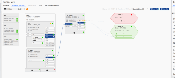
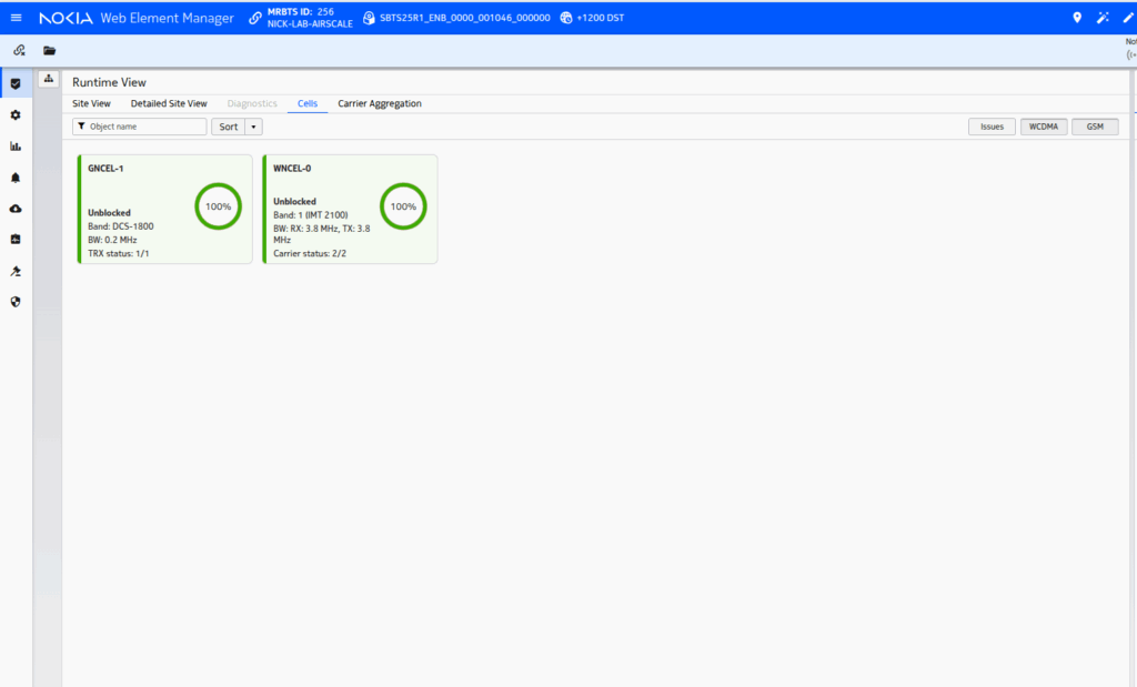
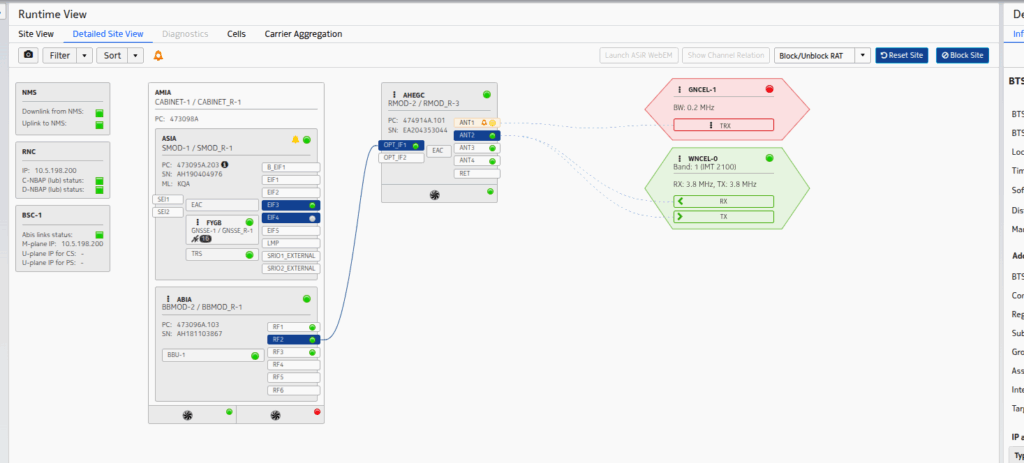
So I fired up the Airscale, configured an Iub link and looked at what it sent.
And the answer was a big fat nothing – the first rule of fight club is that the RNC initiates the connection.
I limped the project along to the stage where I had the cell reporting “Up” and visible, but to actually attach phones started to get into the CDMA part of allocating codes, and real life started to catch up with me.
Perhaps someday I’ll continue the work, but the sad truth is there’s almost no scenarios today where you wouldn’t be better to deploy LTE and a GSM layer if you need to support legacy devices – the smallest UMTS carrier is 5Mhz, and while you can’t do 1:1 frequency reuse in GSM, you’ve got 20x unique GSM TRXes in that same 5Mhz you can use.
So for now, I’m giving up, knowing slightly more about RNC architecture, but still having never done a UMTS attach.
We support a network in Alaska, and one of the guys we work with there – John – has a story (which I’ll steal here) where he gets a phone call late at night from someone saying they’re in the US Air Force, and uh, they’ve, uh, lost a plane. And since John works for the phone company, he wouldn’t have any idea where it is would you? They ask him.
As a matter of fact, John could see the last cell the SIM the pilot was carrying was attached to, they sent a helicopter out and found the pilot, who survived.
This was a long time ago, and he was able to pin the location down to a cell (sector), and lookup which direction the sectors were pointing for that cell and the location of it, to give a pretty good idea of the general search area.
Now that everyone carries a GPS in their pockets, the level of accuracy here is a lot more than just which cell are you served by (although that’s a lot of accuracy anyway, and not to be ignored).
There’s significant privacy implications here and a lot of misinformation about pinging cell towers and “zoom enhance” stuff.
I figured I’d actually share how this works IRL – There’s nothing ‘secret‘ here – All of this stuff is in the 3GPP standards which outline how mobile networks should behave.
There’s roughly 4 levels of accuracy in cell phone networks, we’ll cover each one, and how the network treats it.
(I’m talking 4G/5G here as most of the world has moved on or is already moving on from 2G/3G)
Tracking Area Level Accuracy
Cell sites get grouped into tracking areas, they’re kinda like broadcast domains in TCP/IP networking, when you need to “page” (find) a phone that’s “idle” (sleeping) you page the tracking area.
Tracking Area sizing has sweet spots, you want more than a few cells, commonly about a dozen or so in the same geographic area get lumped into the same tracking area. In regional areas you might have a large geographic area – Up to a few hundred Km in regional Australia for example, lumped into a single tracking area, whereas in a city that might be a single city block.
If you move between cells inside the same tracking area, then your phone doesn’t need to say to the network “hey I’m moving cells” – It’s only if we go over to a new tracking area that the phone needs to wake up and tell the network it’s now in this new tracking area.
(If you’ve got a tracking area that’s too big (too many cells) then it becomes a nightmare to find who you’re looking for, as the paging channels are always blaring out IDs, tracking areas too small and you’ve got phones having to constantly say “hey I’m moving to this tracking area now” – If you want to learn more about Tracking Areas I’ve written about them on the blog before)
The core network (MME/AMF) always knows the location of a phone at minimum to the tracking area – It’s the base level of location the network has to work with.
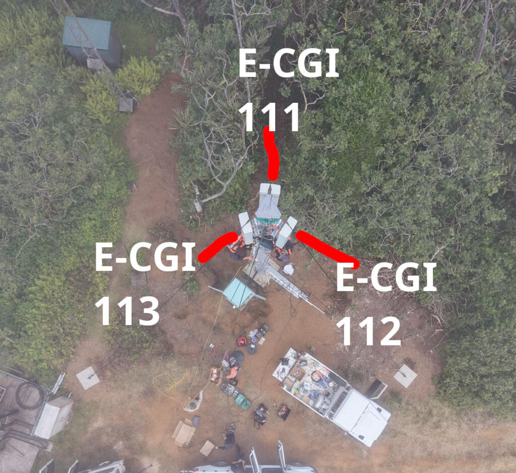
Cell ID Level Accuracy (CGI / E-CGI)
Every cell site sector (cell) has a unique ID to denote which carrier you’re connected to. If you’ve got a 3 sector site, with a single layer per cell sector, then that’s 3 Cell Global Identifiers (CGIs) – one for each sector.
Here’s a tower we put up recently, the CGIs I’ve drawn on are just examples, but if you’re connected to the sector facing North, you’d have CGI of 111, if you’re connected to the cell to the south east, you’d have 112, and the one to the south west would be 113.
CGIs are just numbers, they could be any number, all that matters is that number is unique (ish) in the network, they don’t need to be sequential, or have any common digits.
If we know the CGI of a given user we can kinda draw a 1/3rd wedge off the side of the tower in the direction the antenna is pointing, and if you’re inside that wedge, and that tower is still providing coverage, then we know the customer is somewhere inside that wedge.
But those wedges can still be large, so the margin of error for locating someone is still pretty large. You can probably answer the question of “Are they in the office or are they at home” if they’re in different suburbs.
When the network wants to know a bit more about where the phone is located, it can ask the cell site which Global Cell ID the phone is in, this is pretty rare, but can be done. When the phone is actively doing stuff, like making a call, using data or sending a text, the network knows the CGI of the event.
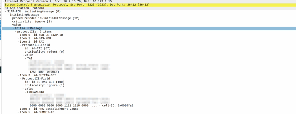
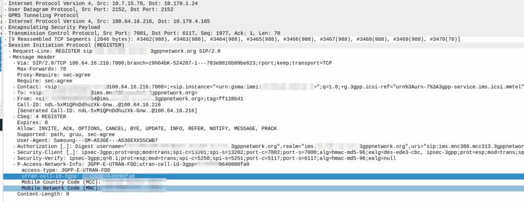
My lab is setup with CGI 4000 and TAC 100, and this information is littered across every signaling message.
Initial Attach message
Note: The encoding shows up as 0000 0000 0000 0000 1111 1010 0000 …. = cell-ID: 0x0000fa0 for CGI 4000, just roll with it, the spec explains why this is.
A SIP REGISTER message from my lab, showing the CGI (00640000fa0)
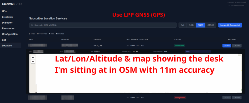
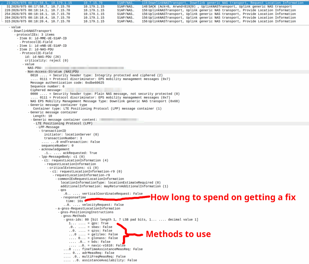
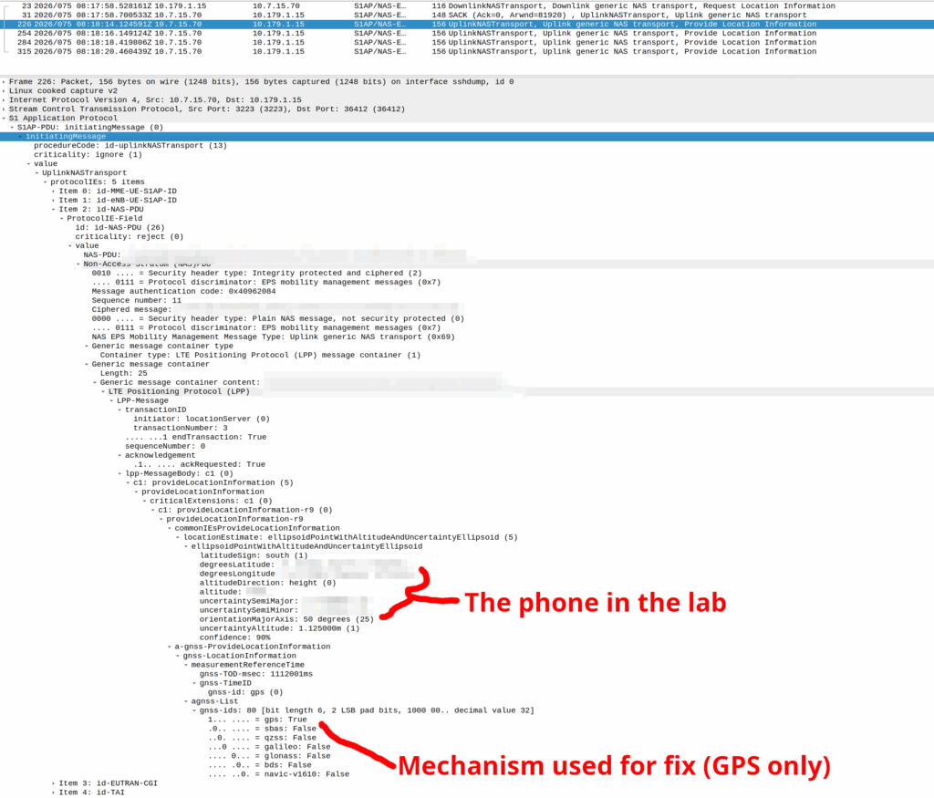
GNSS LPP Positioning
When the Cell ID level is not accurate enough, the network can request the phone to provide it’s location, using whatever it’s got available to it.
In reality, this is either done by an engineer from the phone company with the permissions to do so, or directly by law enforcement using the SLh/SLg Diameter interfaces.
When an engineer does it, there’s usually a portal they can go to, like this one in OmniMME, they search the IMSI or MSISDN, and then can get the location information via a variety of methods.
Your phone gets a message from the network, that says “Hey phone, tell me where you are”.
If you’ve got enough access to the baseband you can even block these requests should you feel so inclined.
I’ve included some Wireshark captures of how this actually looks and how it looks from the Web UI of the MME, with the address removed.
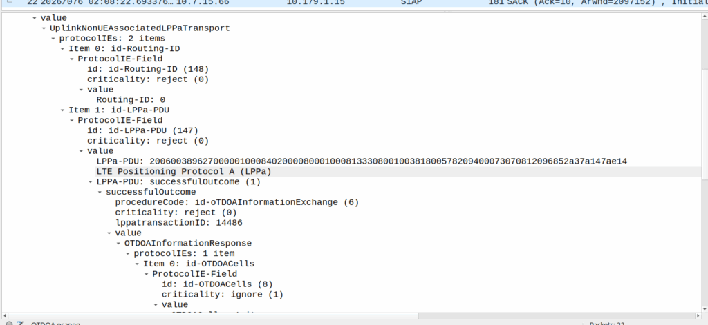
OTDOA – “Pinging”
Sometimes you don’t get an indoor location with GPS or the phone might be too old to support LPP Positioning, no GPS built in or something.
In those scenarios, we use “Time Difference of Arrival” to calculate the position by measuring time between 2 or more cell sites, and calculating the time between when a signal was sent to a phone, and when it receives it, to calculate distance from the base station.
This is better than CGI as it gives you an idea of how far from the cell site the phone is, and the cell site, but it doesn’t return a map with “you are here”, but rather some rough distances, and CGIs for each cell it can see.
The engineer then pulls up a map of all the cell sites, finds the CGIs the cell phone can see, headings for each CGI and tries to do some early high school maths like someones life actually depends on it.
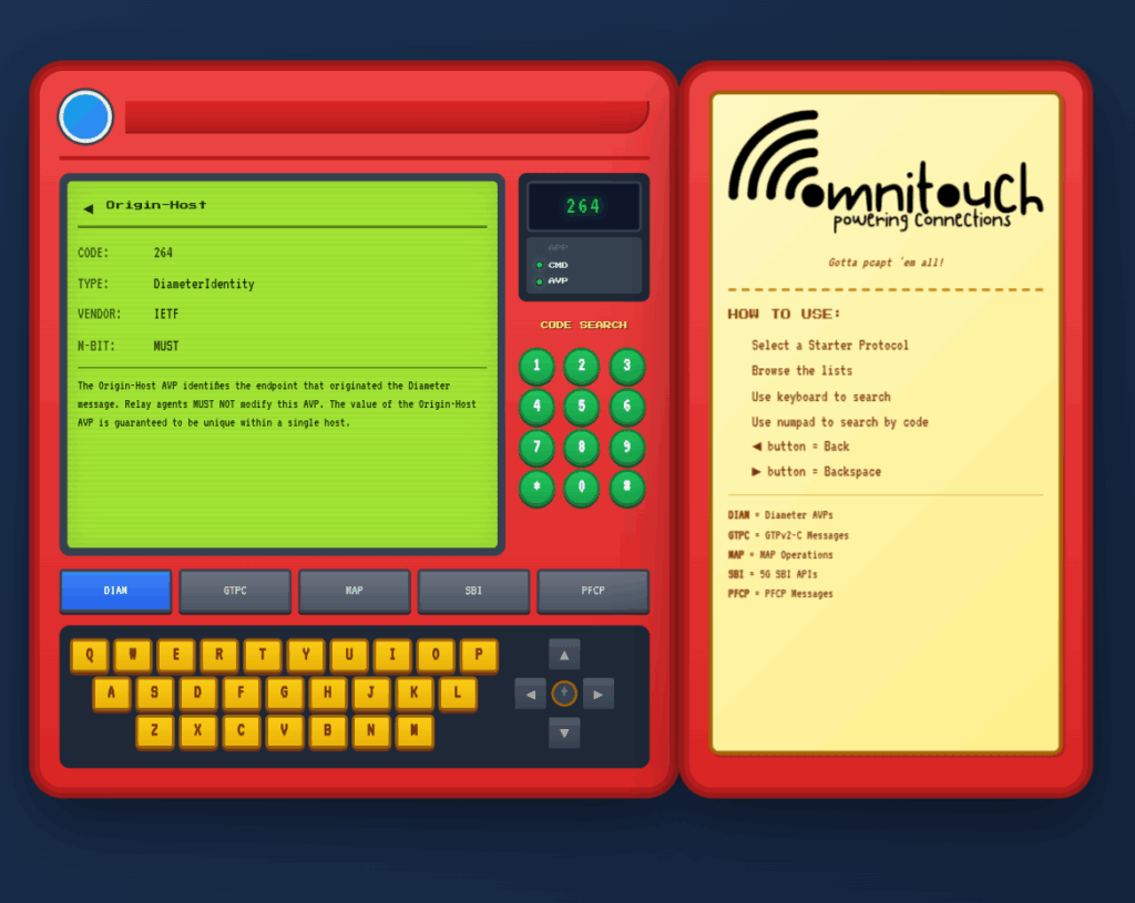
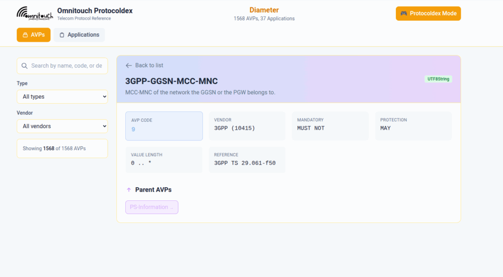
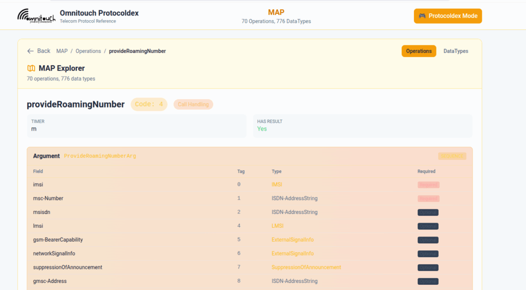
I do a lot of protocol testing, writing Diameter/PFCP/GTP-C etc, and spend a lot of time referencing the standards.
So I built this – Inspired by a 1990s video game / TV / Playing card franchise online reference tool, but rather than identifying pocket monsters, it’s identifying AVPs and stuff
You can punch in the AVP code, AVP name, description, etc, for Diameter, PFCP, GTP-C, MAP or SBI and see all the details to go with it.
I’ve been using it a heap, hopefully some of you might find it useful:
One of our customers is an MVNE and they reached out the other day with an issue.
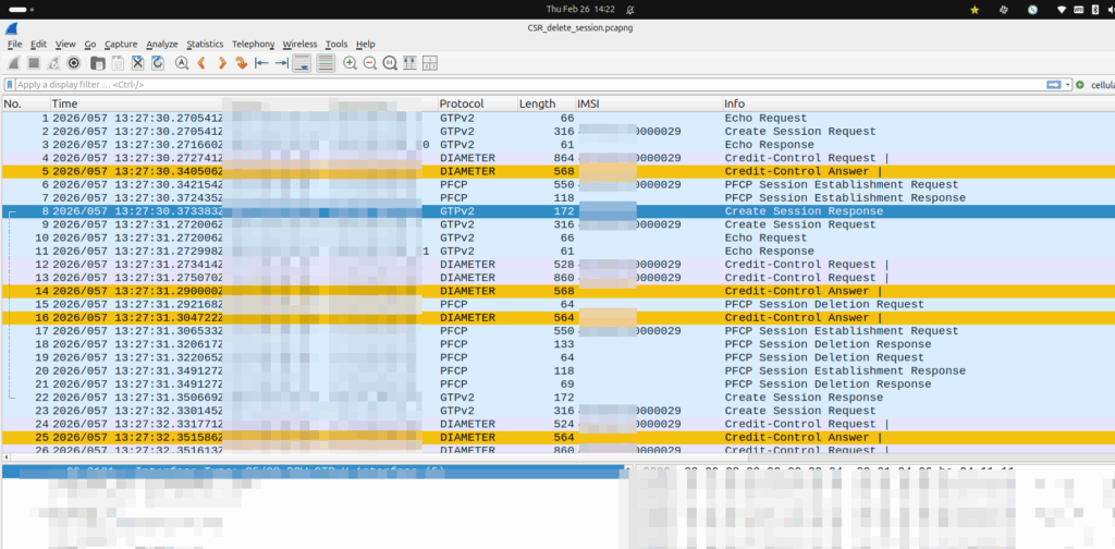
They were turning up a new PGW and they’d see Create Session Request, everything looked OK, it’d get a response, but then in the GUI of the PGW-C they’d see the session drop.
The logs showed the newly setup session dropping shortly after being setup.
Have a look at the screenshot and see if you can work out why:
So what’s going on, and why is the PGW-C deleting sessions?
The initial reaction from the customer was there’s something up with the PGW, but the answer is bit more nuanced.
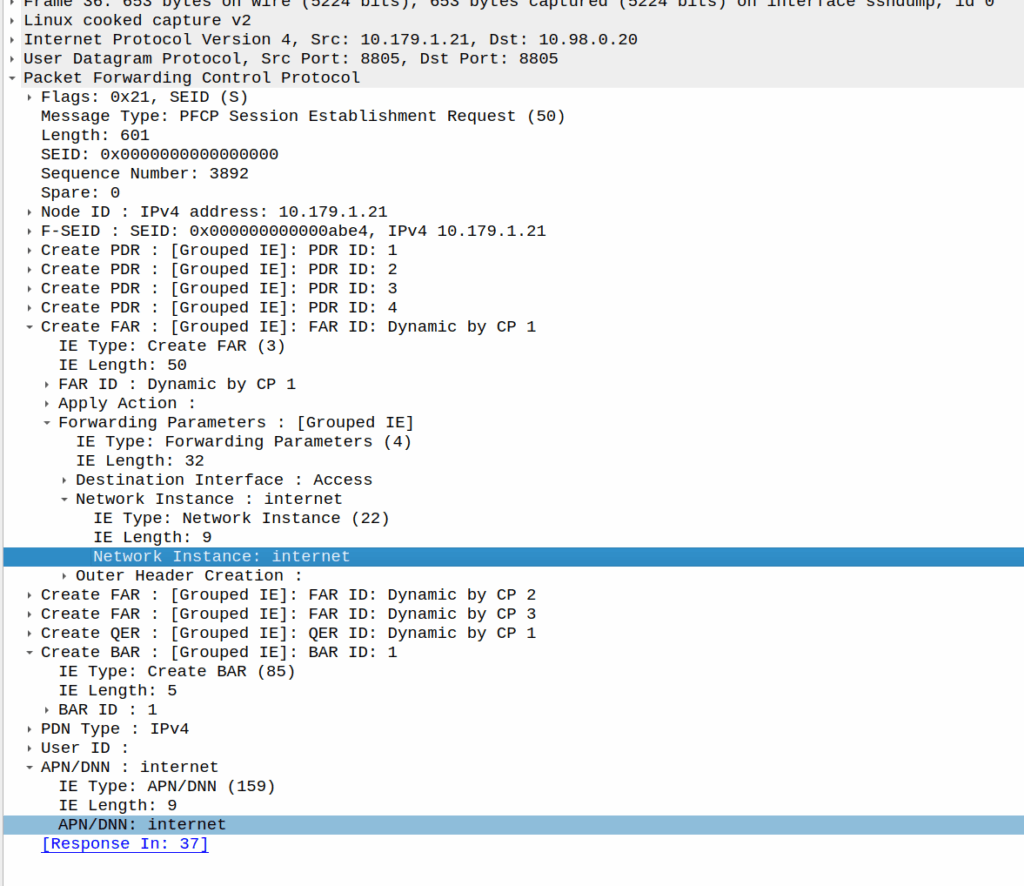
Per the specs, you can’t have two PDN sessions for the same subscriber (IMSI) on the same APN (DNN).
So if 50557000000001 is connected to the PGW-C on the internet APN, if I send another Create Session Request to the same PGW-C, it deletes the old session, before starting the new one.
In this case, the MVNE it was going through was dropping the Create Session Response, so it never made it back to the MNO, and then the MME in the MNO sent it again.
Joys of GTPv2-C being UDP based and connectionless!
When a UE enters Idle mode, the network releases radio resources and the UE enters power saving mode.
When the UE wants to send data (Uplink) the UE just tells the network “hey I want to send something” and away it goes, nice and simple.
But when the network wants to send data to the UE (Downlink) then the UPF needs a method to tell the Control Plane (SGW-C or SMF) that there’s data waiting and to go and page the UE.
A prime example of this is when you’ve got a Mobile Terminated VoLTE call coming in, you need a way to tell the UE to wake up out of Idle mode because you’ve got something to send to it (a SIP INVITE).
But in order for this to work, we can’t just say “Hey I’ve got some packets for you” and let them get dropped, the UPF also needs to buffer (store temporarily) the downlink packets for the UE until the UE comes out of Idle mode, and then flush them out to deliver them to the UE.
So let’s look at the flow.
Enabling Buffering (Idle Mode)
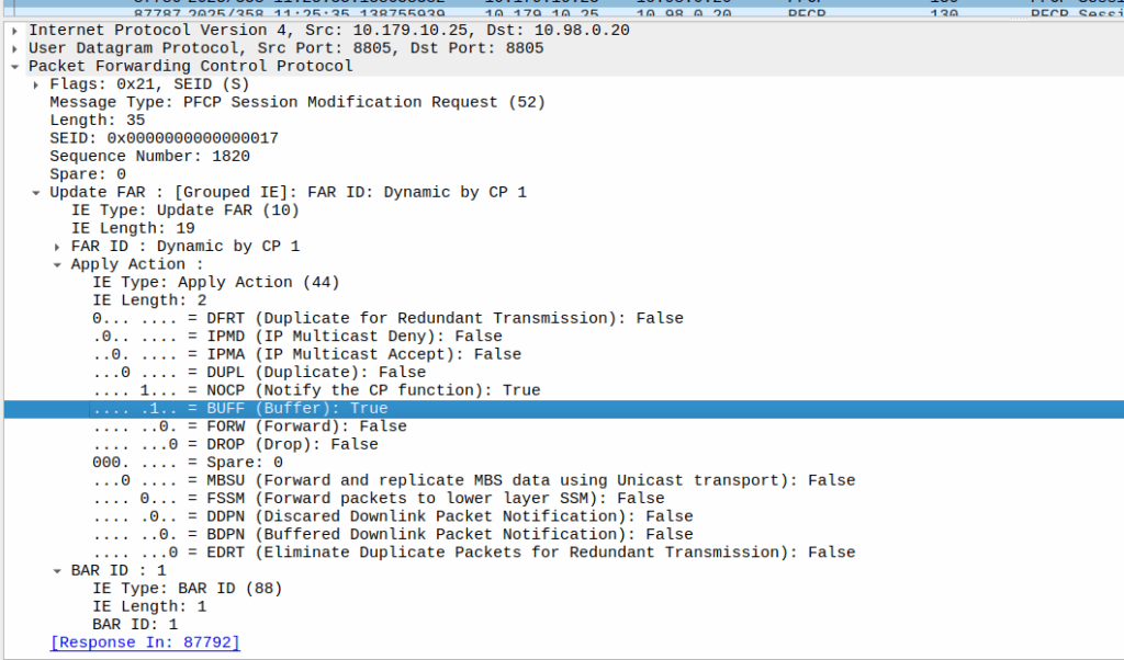
When the sub enters idle mode, the Control Plane (SGW-C for an EPC or SMF for a 5GC) it sends a Session Modification Request but with the BUFF (Buffer) and NOCP (Notify Control Plane) flags set, and FORW (Forward) turned off.
What this means is now for packets to that bearer, the UPF must:
Not forward any traffic
Buffer the traffic
Notify the control plane when the first packet comes in that we buffer
Then the UPF just sits and waits for any incoming packets.
The Notify
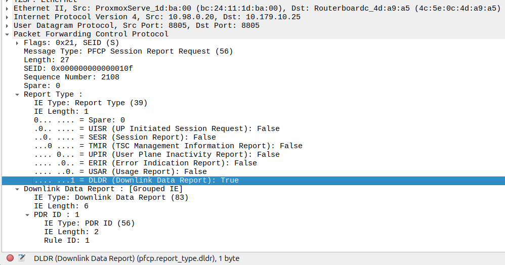
When the UE gets an incoming packet that it’s supposed to buffer and notify, well, it does just that.
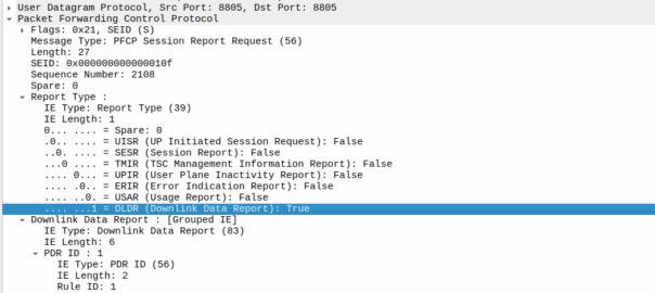
The packets are copied into a buffer, in sequence, and for the first packet, the UPF must send a notification to the Control Plane.
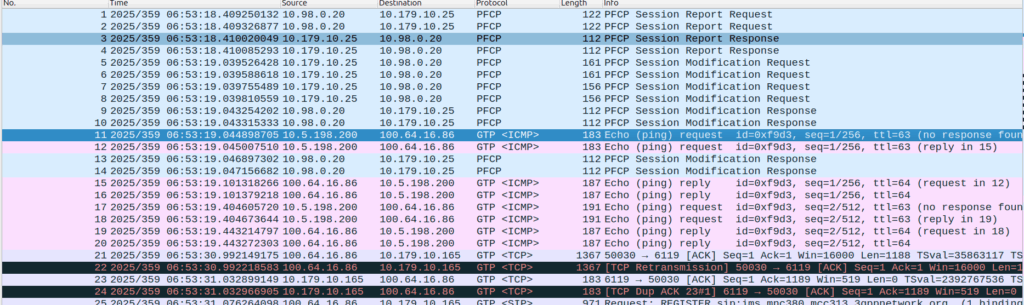
That looks like this, it’s just a Session Report Request with the Dowlink Data Report flag.
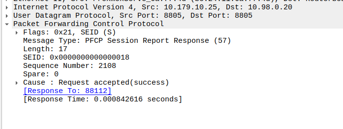
Now the SMF/SGW-U sends back a Session Report Response and starts the process of paging the UE.
At the same time the UPF keeps buffering – It’s work is not done.
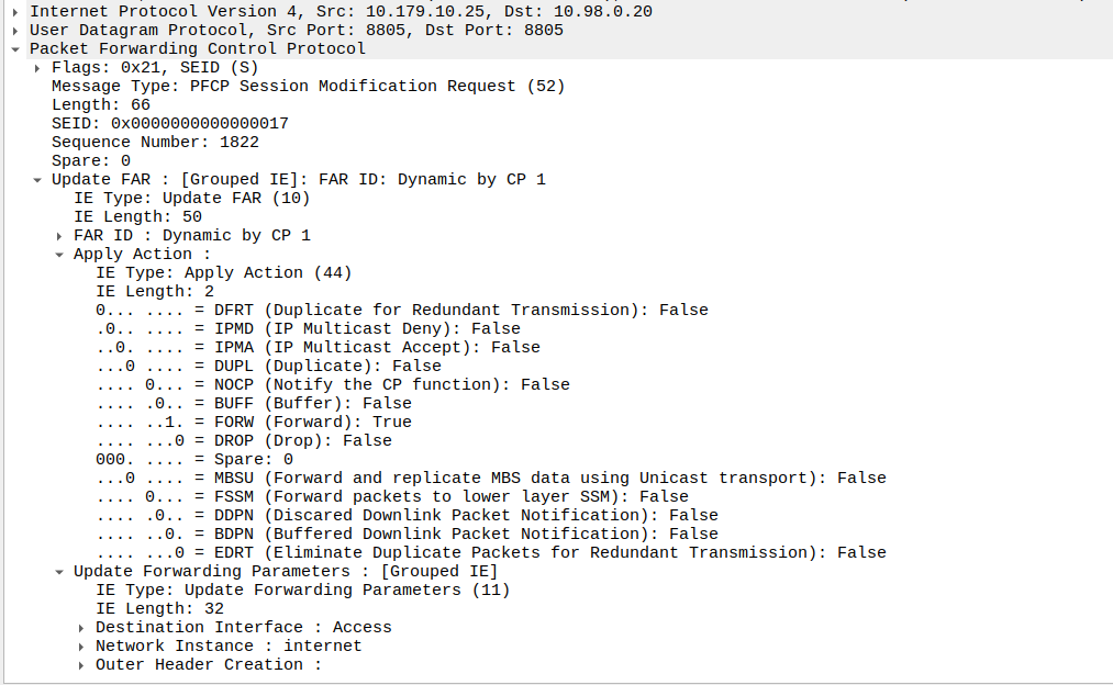
Flushing and Forwarding
Once the UE has become reachable, the Control Panel needs to modify the bearer to turn back on forwarding. It does through another Session Modification Request, this is the inverse of the one it sent to turn on buffering, as we’re turning off buffering and notifications, and turning on forwarding.
Now the UPF flushes it’s buffer – It’ll send all the packets that were queued up out over the wire towards the gNB / eNodeB, so the SIP INVITE for the MT call or whatever will make it through.
One thing to note is that the packets that get buffered are going to take some time to get delivered, as the NOTIFY / page UE / reconnect UE / Session Modification Request (to enable forwarding again) needs to happen before the buffers are flushed and delivered.
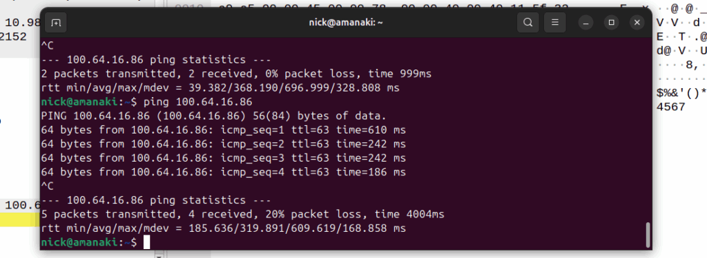
Notice the latency spike on the first packet? 610ms? That’s because the UE had to be paged to wake up.
And that’s pretty much it, the UPF has now flushed it’s buffers and moves back to forwarding actions.
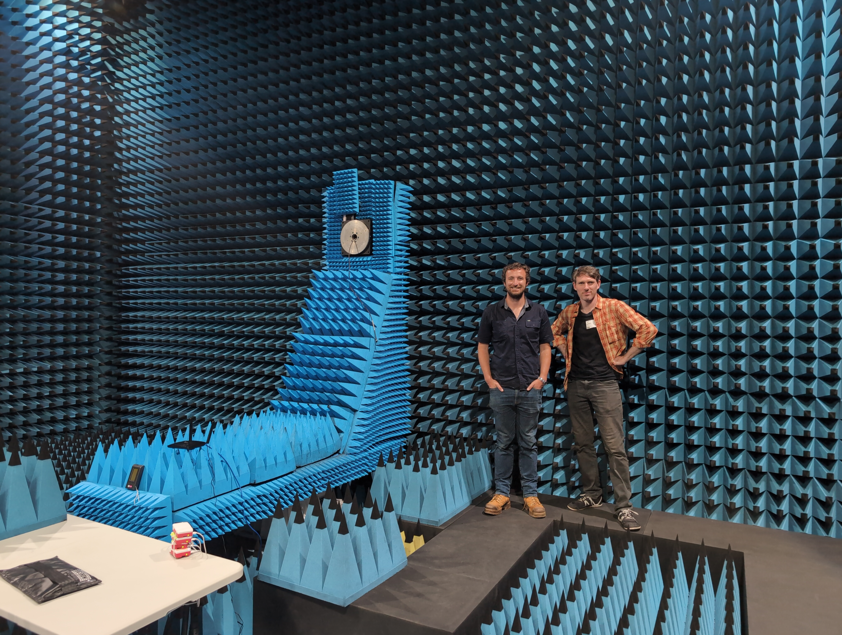
I was recently in Sydney for a GSMA event with a few extra days in town to show one of our team members who was visiting from the US, around a city I don’t even live in.
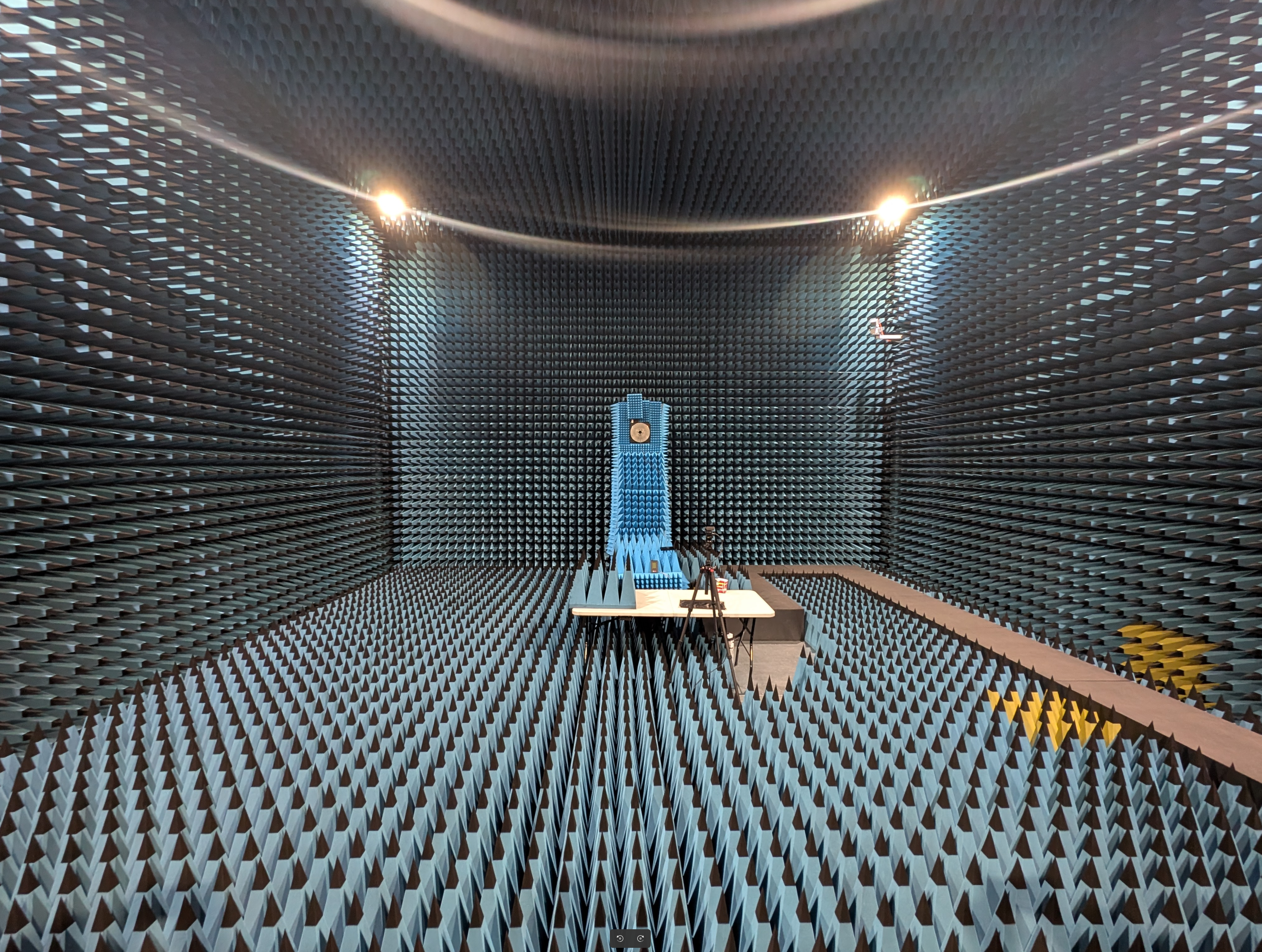
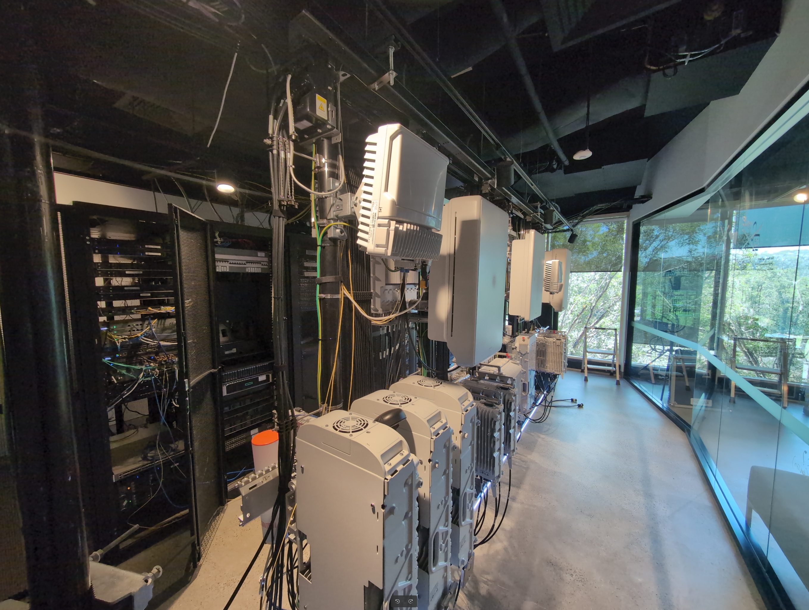
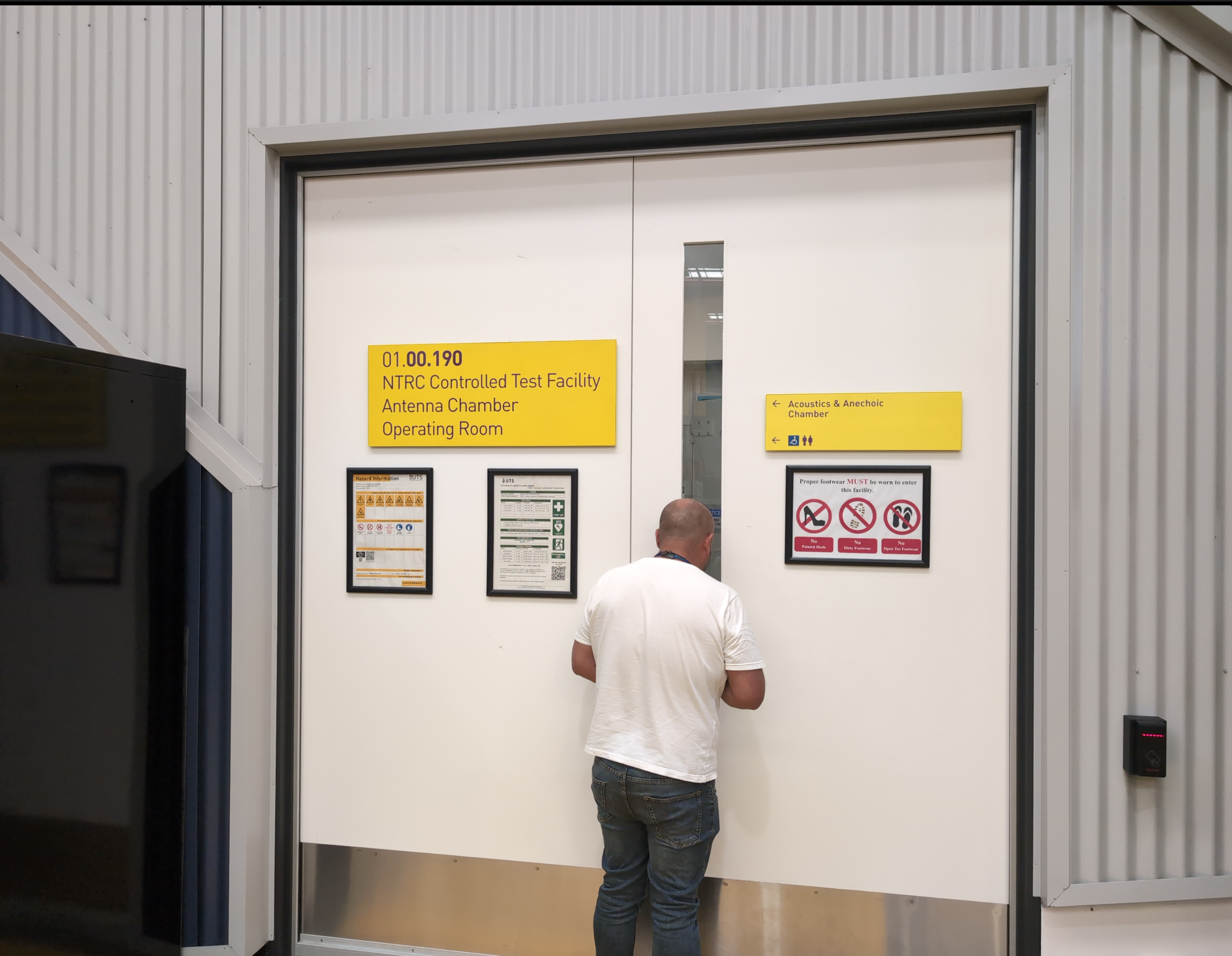
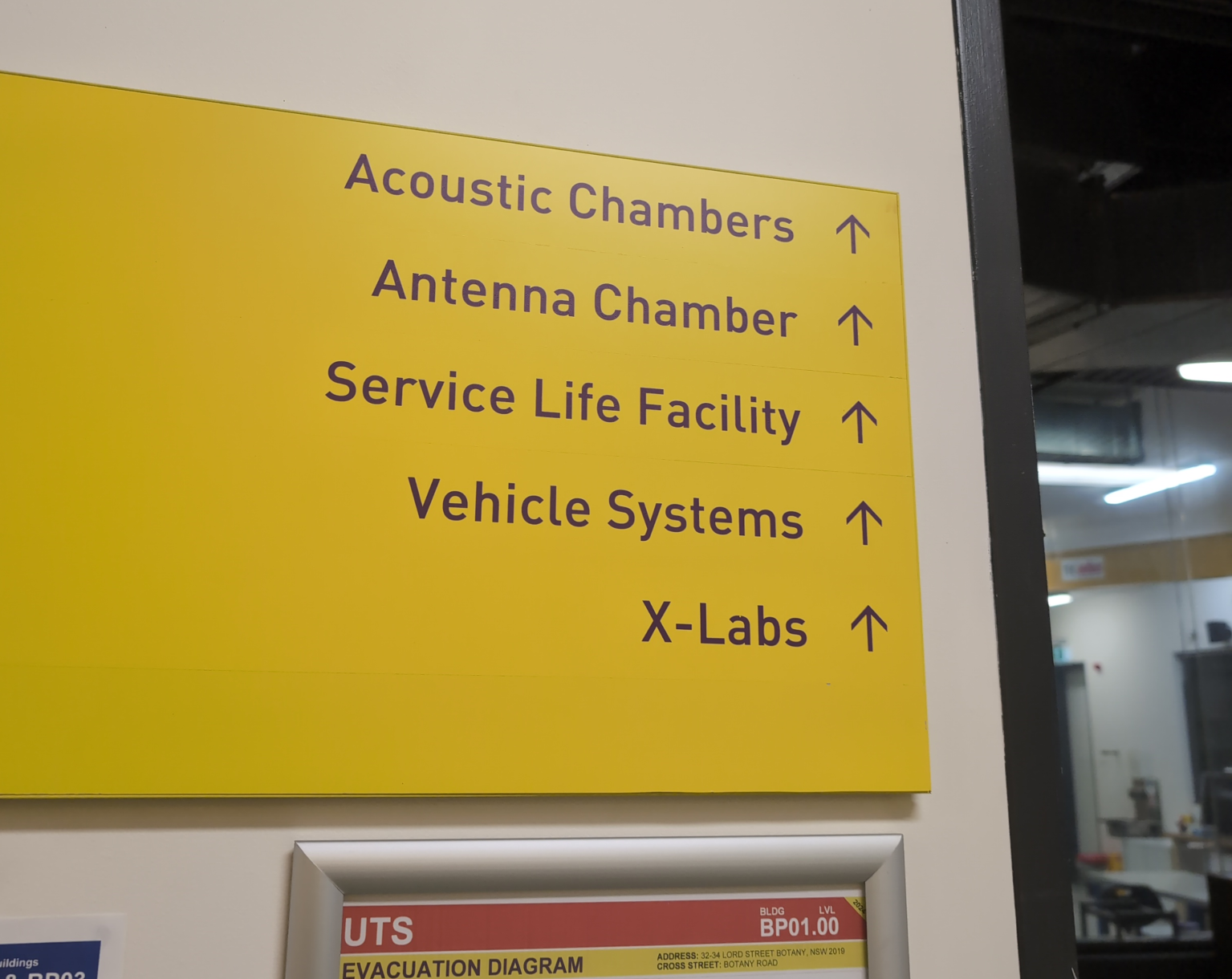
So I reached out to our Nokia account manager and asked if I could visit “The pointy room” – The antenna chamber they’ve got there and Nokia lab.
It did not disappoint.
As well as all the fancy RAN kit and pointy room, they’ve got the kind of machine shop I dream of.
Thanks to Paul, Dave and Ed for showing me around.
We also had a few days hiking in the Blue Mountains, not as impressive as RAN kit.
I was recently looking for a field I could use in PFCP to denote the VRF / Network Segment to be used, and initially thought Network Instance would be perfect for this.
It’s not.
Network Instance is kinda preferred over the APN/DNN for decisions, for example a Packet Detection Rule (PDR) does not give a damn what you’ve set as the APN/DNN, only what the Network Instance is set to:
a combination of the parameters, that incoming packets are requested to match, among: Local F-TEID, Network Instance, UE IP address(es), SDF Filter(s) and/or Application ID. For 5GC, the PDI may additionally contain one or more QFI(s) to detect traffic pertaining to specific QoS flow(s), Ethernet Packet Filter(s) and/or Ethernet PDU Session Information (see clause 5.13.1).
Our team recently shipped a new UPF which is a huge improvement on our old UPF, and I drew the short straw of doing all the interop testing for the IMS.
Initially I thought there was an issue with IP routing, as I’d never see the SIP register from the UE, but I would see the IMS APN coming up.
I could access the internet from the UE IPs just fine, but that’s going to public IPs, whereas the P-CSCF is in private address space, and hosted on the same box as the UPF.
I spent hours on this as my lab servers do routing on a stick, and I thought some hardware offload somewhere was trying to fast path my packets and send them back to the server without going via the router.
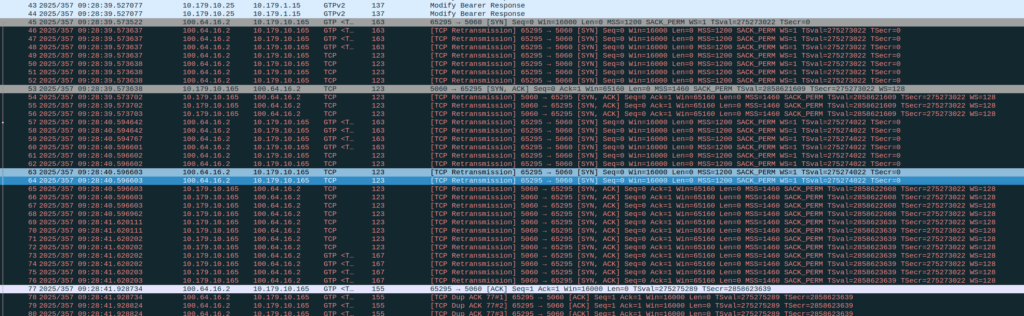
Then I dug a little deeper and found I could see the 3 way handhake between the UE an the P-CSCF, but no SIP packets.
Successful 3 way handshake between the UE and the P-CSCF on TCP 5060
This was confusing, clearly we had at least intermittent two way comms – the 3 way TCP handshake confirmed that, but then why were packets not getting across?
We have an XCAP server hosted on our P-CSCF instances, so I tried hitting that from the phone in case there was something weird about routing to the network segment that hosts the P-CSCF, but I could hit the XCAP server just fine, so now I was certain the UE IP pool could route to the P-CSCF and 3 way handshake for TCP was working and payload could be pushed.
Clearly we can route to the P-CSCF as that’s where this XCAP server is hosted
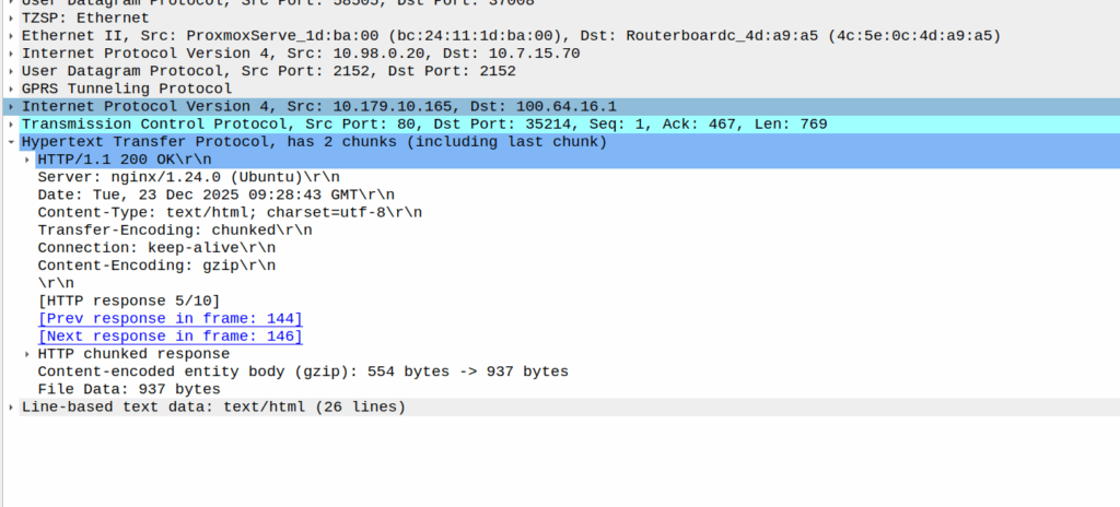
Then I dug into what happened after the 3 way handshake, and I found a TCP payload containing the start of the SIP REGISTER.
Hmm, we have a SIP Fragment here at least…
I traced it all the way through and lo, it’s hitting the P-CSCF:
And the fragment is recieved on the P-CSCF
Okay, but then what happens, because it’s only a fragment, not the complete re-assembled packet, so what’s going on?
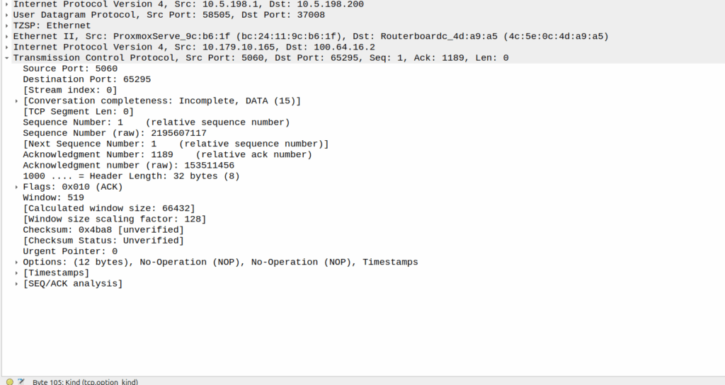
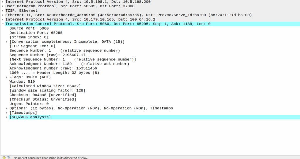
Well, the P-CSCF sends a TCP ACK back to the UE.
And the TCP fragment containing the first part of the REGISTER gets an ACK back from the P-CSCF
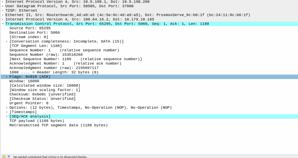
The ACK gets forwarded to the UPF:
And that TCP ack makes it to the P-CSCF
And then… Nothing? The UPF never encaps the TCP ACK back into GTP-U and never sends it onto base station.
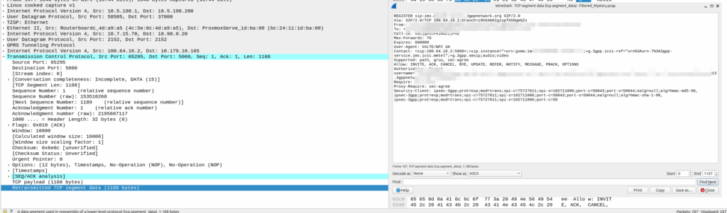
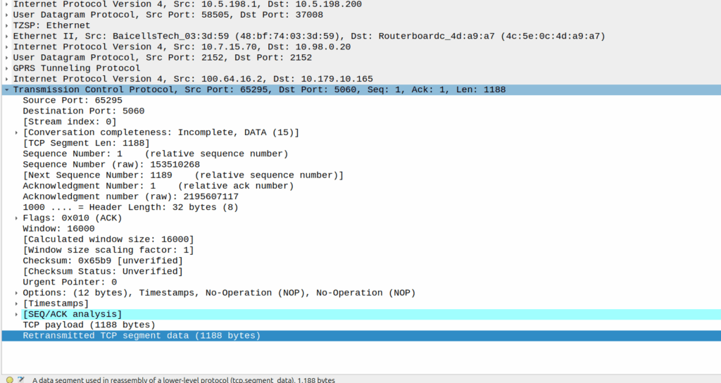
Eventually the UE re-sends the payload with the start of the REGISTER, but it does not get the ACK from the P-CSCF.
Retransmitted TCP segment containing the REGISTER from the UE
So naughty UPF right? Not forwarding that ACK for some reason?
I started digging, maybe the ACK was getting routed weirdly and landing on the UPF without going through the router?
Well not quite…
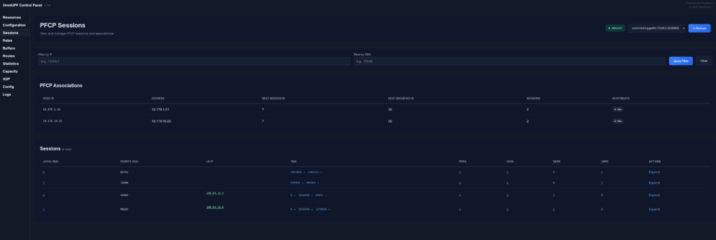
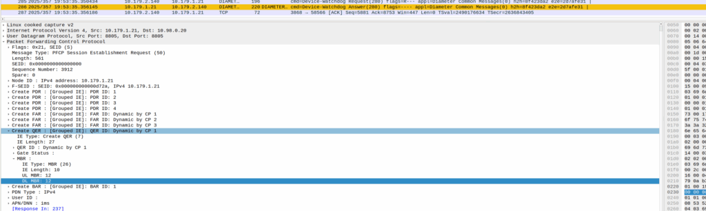
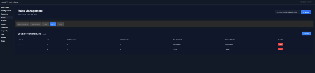
When I started digging into the QER rules being installed I noticed the MBR bitrate we had on the IMS APN in the HSS was tiny.
The UPF can only gate on traffic to the UE, so was gating the ACK traffic, as the QER had consumed all the bandwidth so the ACK never made it back.
Time wasted – About 4 hours, but I will not make this mistake again!
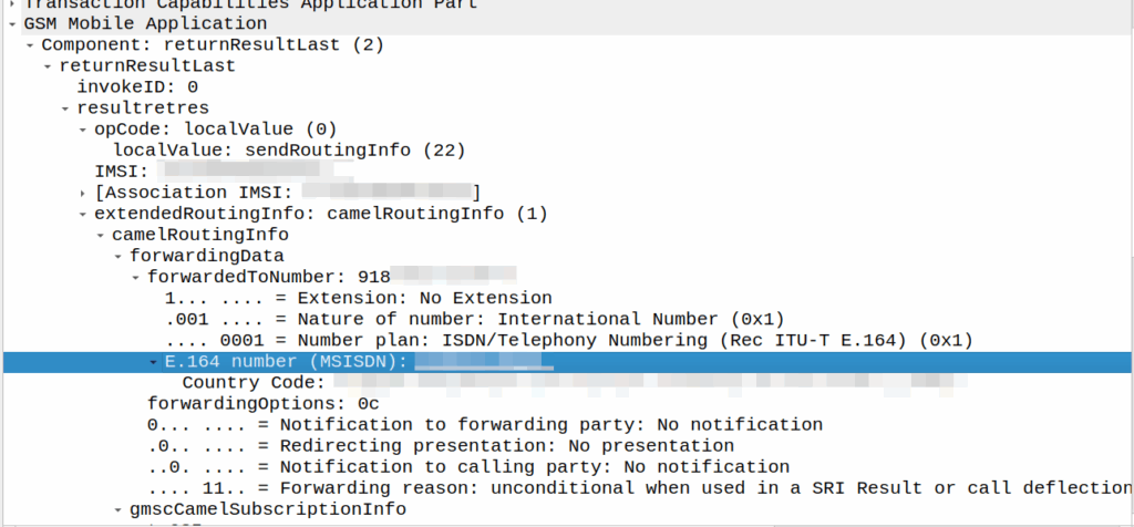
I’ve covered how SS7/ISUP handles call forward before, but the HLR can also store call forwarding information.
This is returned to the MSC when the SendRoutingInfo dialog is performed against the HLR.
If it’s present the MSC will redirect the call to that destination, after bouncing it through CAMEL (if enabled).
A lot simpler than Call Forward in IMS, but same outcome.
A lot of HSSes we see are just HLRs under the hood and only implement a minimalist MMTel feature set for call forwarding for this reason to have it track across both.
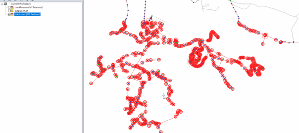
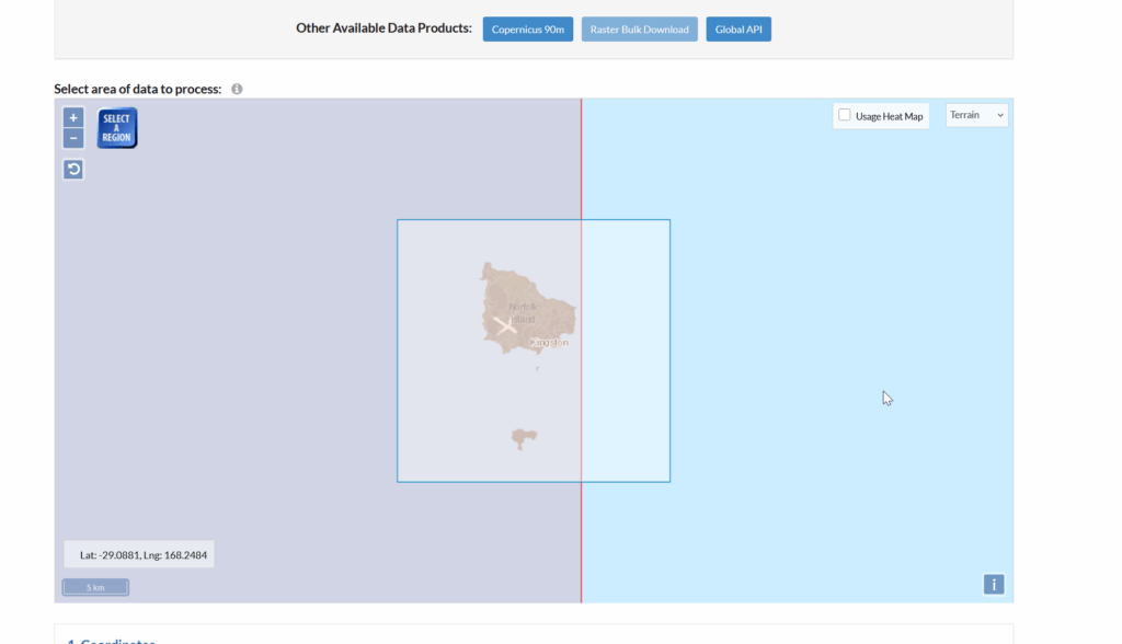
Looks like this is my 3rd (and hopefully final) post on the topic of loading Digital Elevation Models / Topographic data into Forsk Atoll, because this time, we’ve got global data, which allows us to Digital Elevation Models, at 30m resolution, for anywhere on the planet.
The Copernicus DEM is a Digital Surface Model (DSM) which represents the surface of the Earth including buildings, infrastructure and vegetation. This DSM is derived from an edited DSM named WorldDEM, where flattening of water bodies and consistent flow of rivers has been included. In addition, editing of shore- and coastlines, special features such as airports, and implausible terrain structures has also been applied.
The WorldDEM product is based on the radar satellite data acquired during the TanDEM-X Mission, which is funded by a Public Private Partnership between the German State, represented by the German Aerospace Centre (DLR) and Airbus Defence and Space. OpenTopography is providing access to the global GLO-30 Defence Gridded Elevation Data (DGED) 2023_1 version of the data hosted by ESA via the PRISM service. Details on the Copernicus DSM can be found on this ESA site.
This is a tool for a job, 30m resolution is not crazy high – LIDAR scans achieve sub 1m accuracy, but aren’t available everywhere, where as the COP30 dataset is global, meaning we can do RF design for anywhere on the planet.
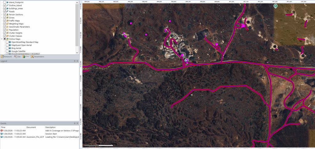
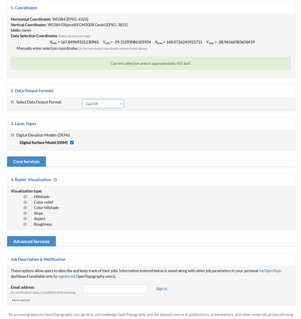
So how do we get this into Atoll to do RF modeling?
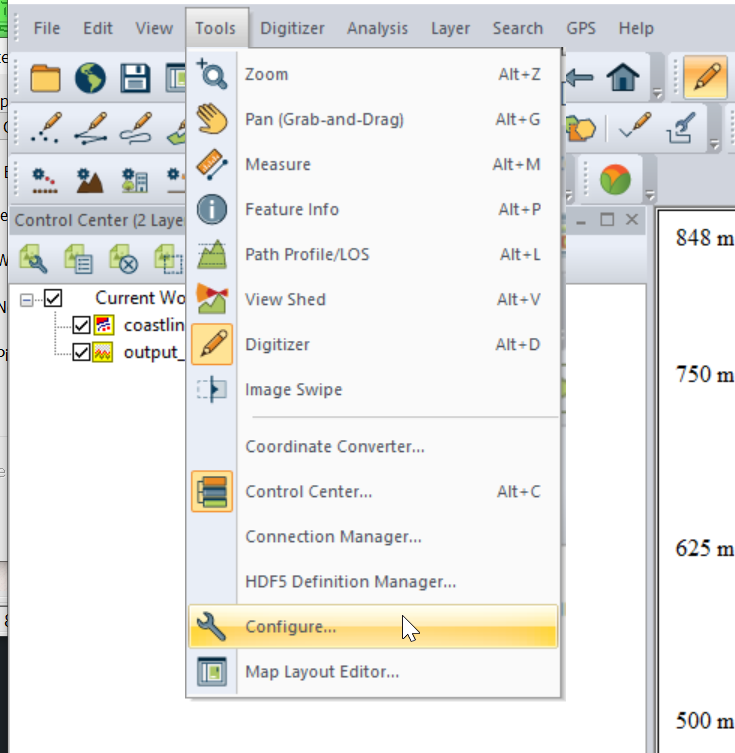
I had to re-project the data, so inside Global Mapper I had to go to Tools -> Configure.
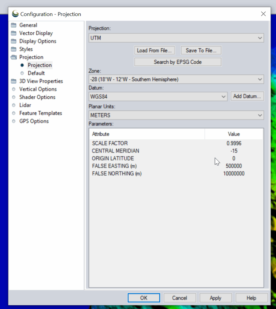
Then change the projection to UTM and use the UTM Zone Finder to find out what zone I needed.
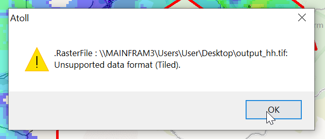
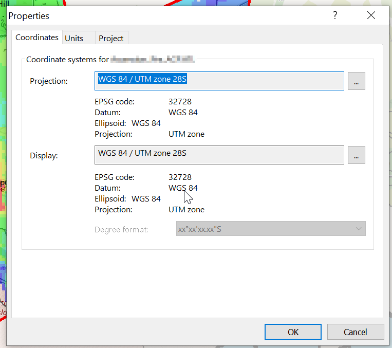
Then I exported the data as an Erdas Imagine file and was able to imported happily into Atoll, after setting the matching projection in Atoll (Which you generally do at the start of the project).
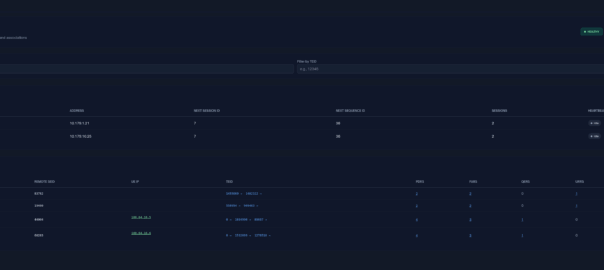
SMSc can send an SRI-for-SM, and if the subscriber is absent, the response can include the informServiceCenter message, which lets the SMSc know if it will get sent an alertServiceCentre message when the subscriber comes back online (sends an UpdateLocation).
This means that the SMSc can be notified when it can deliver the message to the subscriber.
It’s got a bunch of flags, which equate to:
sc-AddressNotIncluded means the service center address from the SRI-for-SM was not included in the Message Waiting Data file (and therefore will not get notified via AlertSC when the subscriber comes back online).
If it’s sc-AddressNotIncluded is set to False it means that the service center address has been added to the Message Waiting Data file, so will get an alertServiceCenter message when the sub comes back online (Double negative).
mnrf-Set means Mobile subscriber Not Reachable (Not registered on any MSC)
mcef-Set means Memory Capacity Exceeded Flag is set as the HLR has run out of memory in the Message Waiting Data file and cannot store any more data (So you won’t get notified via AlertSC when the subscriber comes back online)
mnrg-Set is for Mobile subscriber Not Reachable for GPRS (When using SGSN delivery is not registered for packet service).
mnr5g-Set means the SC will get notified when the subscriber becomes reachable from 5G serving nodes.
mnr5gn3g is a mystery – The only references to it I can find are in the ASN1 spec (hence why Wireshark decodes it) but as to its purpose, I can only guess.
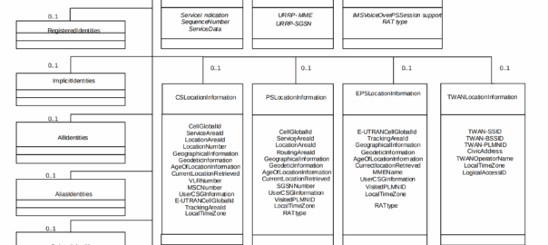
A concept that’s always been a bit unclear to me was how the Sh Profile, XCAP data for call forwarding / barring and RepositoryData all fit together.
Let’s start off with the basics.
The Diameter Sh interface sits between an Application Server (Typically TAS, SMSc, XCAP server, etc) and the HSS.
This AS can run a Diameter User Data Request to get the contents of Sh Data, which is returned in the User Data AVP (702) for a given subscriber.
Application Servers can also subscribe to be notified of changes in the Sh data on the HSS, by sending a Subscriber Notification Request, and when the data changes they’ll get a “Push Notification Request” to inform them of the change.
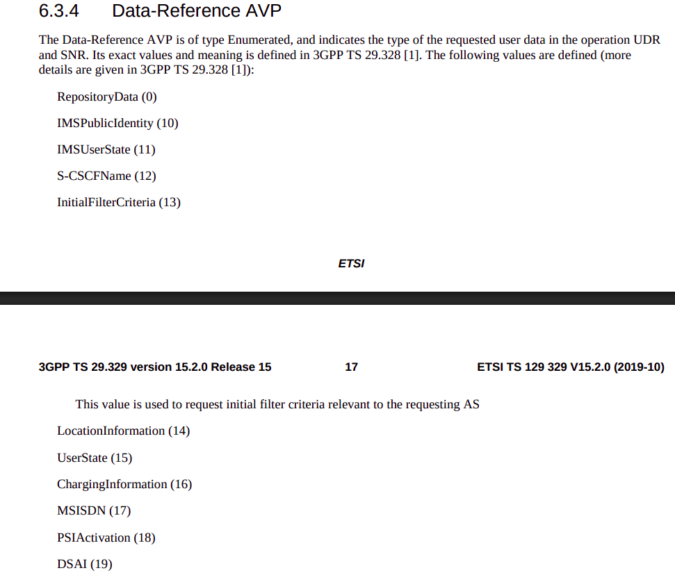
When sending this User Data Request the AS can specify what data it wants to get returned, for example an AS might want to know the current S-CSCF of a given subscriber, in which case, the AS would set the DataReference AVP (703) to 12 for S-CSCFName.
Not the complete list…
The the AS can request can be public and private identities (IMSIs and MSISDNs), location in the PS and CS networks, TADS info, SRVCC parameters, etc, etc.
Data like TADS Info, CS and PS network location, Public and Private identities, come from the HSS and cannot be modified, these values either come from the static subscriber definition in the HSS (what was set when provisioning the subscriber), or based on the subscriber’s state (ie where they’re registered on the network).
RepositoryData
But there is a section of data we can request the HSS return called RepositoryData which can be modified/updated by the end user or other applications in the network (Modified by ASes), via a Profile Update Request.
This data is where we put the call forwarding, call barring, caller ID presentation/restriction info – The HSS doesn’t really care what is stored in RepositoryData, it’s just a transparent place to store this data.
Think of it as a simple folder containing text files, each text file has a name (ServiceNotification) which allows us to reference the blobs of data by name, a SequenceNumber to identify duplicates, and then the actual contents of the file itself ServiceData.
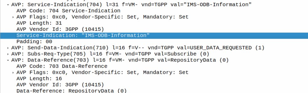
We can then request the contents of these files from the HSS by calling DataReference of RepositoryData and setting the ServiceIndication to be the “file” we want returned to the AS by the HSS.
For example, if the Data-Reference AVP is set to zero (Repository Data) and the Service-Indicator AVP is set to “IMS-ODB-Information” the HSS will return the data for the file IMS-ODB-Information of repository data.
This RepositoryData is just “transparent” storage of XML data by the HSS, and this is where we’d put Call Forwarding, Operator Defined Barring and CLI presentation/restriction parameters.
In theory you could also store 3rd party custom unstructured data here (Move over AWS S3 buckets, I’m moving all my storage to Diameter!), but it’s not commonly used beyond call routing parameters.
The two most common types of ServiceIndication keys you’ll see stored in RepositoryData are MMTEL-Services and IMS-ODB-Information. Each of these are defined by their own XML spec, but the MMTel-Services key is where all of our Call Forwarding, Caller ID Presentation/Restriction parameters live, while IMS-ODB-Information contains the parameters for Operator Defined barring – Both of these XML definitions we’ll dive into in a post of their own, but for now all you need to remember is that they’re stored transparently as XML on the HSS.
An example use case of this would be when a user wants to manage their call forwarding data via XCAP. When the user pulls up the Call Forwarding menu on their phone, the first entry point will be the XCAP Server (AS) to get all the User Data for MMTelServices, so it’ll do that via a Diameter User Data Request with the DataReference set to RepositoryData and the ServiceIndication set to MMTel-Service so the XCAP server can pass the full XCAP XML body to the UE.
The UE can then update this data, and the XCAP server just sends a Profile Update Request to push the updated XML to be stored on the HSS.
Fitting this all Together
Data sent to the AS by the HSS will always include the <Sh-Data> XML, but the child keys within it depend on the data the AS requested under the Data-Reference.
If we requested IMSI as the DataReference, then the returned XML might look like:
<Sh-Data>
 <imsi>9990112345677</imsi>
</Sh-Data>
Likewise, if you requested IMSPublicIdentity as the DataReference you’d get:
The spec goes into full detail on all the possible keys, but in short, when the AS queries the data for the provided DataReference, the HSS sends back an Sh-Data XML body containing at a minimum those keys.
Recently we ran into an issue with certain devices while roaming not including an ICSCI field in the Contact header while registering onto the IMS, leading to MT call failures.
So what is ICSI and why were these calls failing?
The IMS standards are littered with novel ideas for smart telephony features that no one ever implimented, and presents a minefield of conditionals about features you never even knew existed.
Today’s dead feature is the “IMS Communication Service Identifier” (ICSI), no, it’s not a TV show about IMS Crime Scene Investigators (don’t steal my pitch), instead ICSI identifies IMS services by using “IMS Enablers” which allows multiple IMS applications to run on the phone.
It’s like a VLAN or a VRF but for IMS, one IMS stack but multiple sub-IMS stacks I guess.
Why would you want to do this you might ask? Well, the example from the Specs is if you were using OMA’s very short lived OMA Instant Messaging and Presence application, which uses SIP for transport, but needs the SIP messages routed to the OMA client application in the phone, rather than the standard IMS SIP client in the phone for making calls / texts.
Alternately, you could have a mobile PBX application for office workers, and with a different ICSI this could use a secondary dialler with a contacts list and presence for all your co-workers, these sorts of “sub” IMS clients and applications were possible with ICSI.
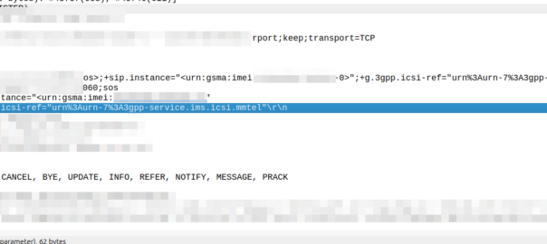
So how does it actually work? Well, it’s stupid simple, during register the phone indicates in the Contact header what ICSI applications that client supports.
When a call is made by the UE based on this value the iFCs can route to different Application Servers based on the values.
For mobile originated calls, the terminal in this scenario is kinda meant to work like a SIP Proxy, dispatching a SIP message to the correct application (in the terminal another IMS client that spoke to the main phone).
In reality though, there is only one ICSI service seen in 99.999% of IMS traffic and that’s the 3gpp-service.ims.icsi.mmtel ICSI, used by IMS clients to denote that they support IMS Multimedia Telephony, aka just normal IMS.
For reasons best know to VENDOR X (you know who you are) their phones include the 3gpp-service.ims.icsi.mmtel in the Contact header when registering on the home network, but while registering while roaming do not include this.
Our TAS ignores the lack of ICSI for mmtel in the contact on regular MT calls, but one of the other TAS vendors in the mix got grumpy because it was missing, and they didn’t have a contact for MMtel for the registered subscriber.
In the end we rewrote the headeron on our CSCFs before passing it to their TAS, which resolved the issue.
Who’s in the wrong? Well, the particular phone vendor who doesn’t include MMtel in the ICSI Contact, but that’s not going to change any time soon. So as the old saying goes, if the mountain won’t come to Mohammed… Mohammed will rewrite SIP headers.
Here’s a Kamailio question I posed to the mailing list the other day:
I’m working on a scenario with a Kamailio box with a private IP, with a public IP 1:1 NATed to it (but the VM does not see the public IP on the NICs).
When forwarding requests to some hosts I want to set the Via address to be the public IP, but when forwarding requests to other hosts I want to leave the Via address to the internal IP address.
If I set the Advertise parameter in the bind config, this sets the Via to the advertised IP, but I’m seeing that address used even when communicating with hosts on the private IP.
Of course if the IP was on the VM itself I could use $fs or force_send_socket, but that only works if I’ve got the public IP bound, which I can’t do.
Is there a simple way to set / override what IP gets baked into the Via header?
Where you’ve got multiple IPs on your box, you can include the advertise paramter to override the IP you show, for example if you have the IP 100.64.253.251 on your NIC, but you’ve NATed the traffic and instead want to show 1.2.3.4 you can set this in the general config:
But then every message Kamailio forwards, will contain the 1.2.3.4 address int he Via header. For my scenario, this didn’t work, as I wanted to only use the 1.2.3.4 IP when communicating with hosts outside of the RFC1918 address space (only conditionally use that address).
Because of this I couldn’t use the advertise option, but I found the set_advertised_address() function to use in my routing logic, where I set the advertised address just on the given routes I care about:
#General Config:
listen=tcp:100.64.253.251:5061


#My routing blocks that go to hosts outside RFC1918 address space:
                rtpengine_manage("media-address=1.2.3.4");
                set_advertised_address("1.2.3.4:5060");
                msg_apply_changes();
So now any packets by default will have a Via of 100.64.253.251 but when I want to I can set the Via to the 1.2.3.4 public IP (and I do the same in RTPengine).
Well Android cleverly has formatted this message so that it has special meaning on Android phones, but non-android phones, will just see:
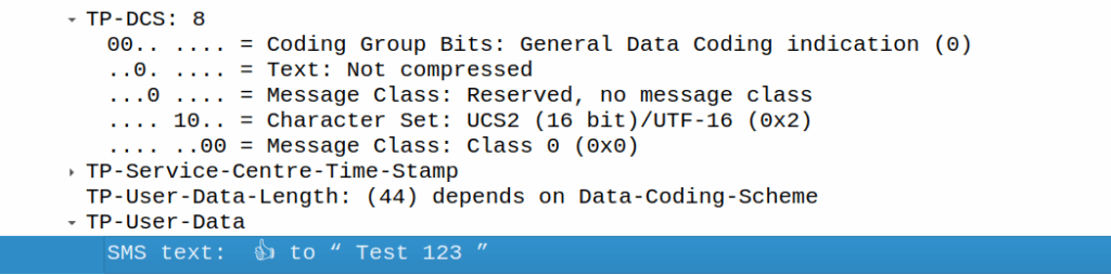
👍 to ” Test 123″
Breaking it down:
200A is Hair Space followed by 200B which is a Zero Width Space (This is metadata for Google’s messaging app) to denote it’s an emoji. This is really clever, as these characters mean it’s an emoji reaction to a previous SMS, but they don’t render as visible characters if the user is on a phone that doesn’t know how to treat it.
Our UTF-16 thumbs up is represented at D83D DC4D (Surrogate), and then the original message is quoted after it.
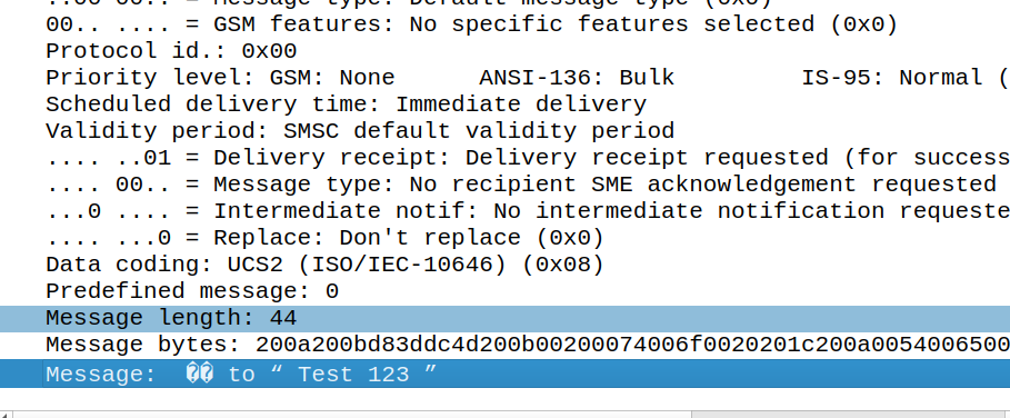
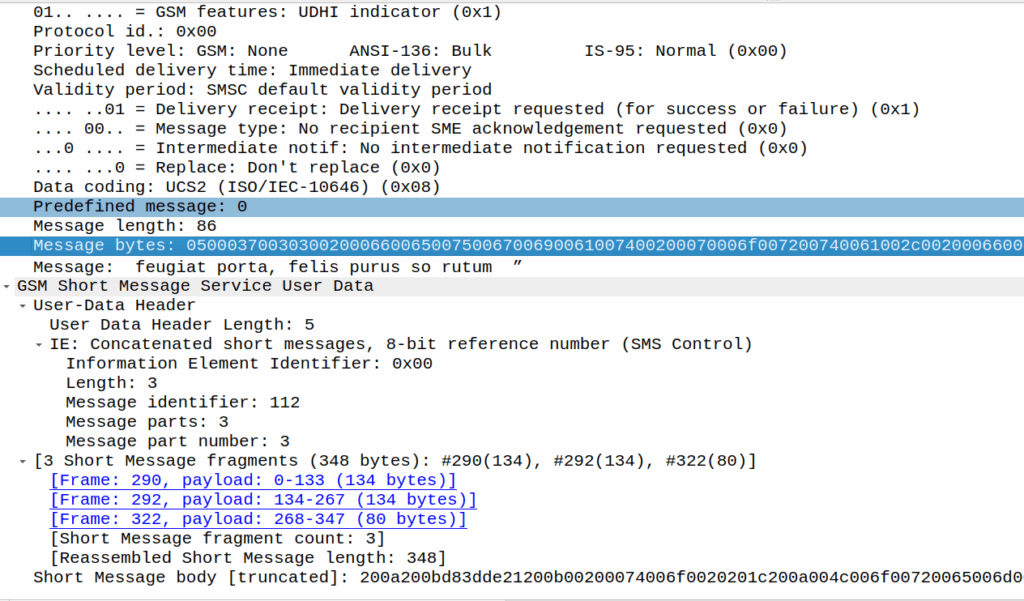
As a fun aside, this does not work if the original message was near the limit of a single part message, as the original message is quoted, so what happens then?
Here’s a MO message that’s exactly 160 characters:
If I react, the original message (160 chars, GSM7 data) is included, but as we’re including an emoji, it must be UCS2 (essentially UTF16) as the emoji isn’t part of the GSM7 alphabet.
In this case, this ends up being a 3 part message, the original text has almost doubled in size as it’s now in UTF16 – it was 140 bytes before (140 bytes fits 160 GSM7 characters) but is now 320 bytes (140 characters at 8 bytes each) + the 8 bytes for the hair space + whitespace + 8 more bytes for the emoji + the 6 bytes UDH header per message, brings us to a whopping 347 bytes not including overhead.