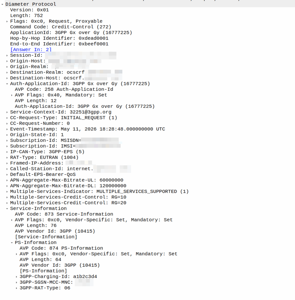
I was recently asked by a potential customer if we supported Gx over Gy.
I’d never heard of this before, so I gave my standard “If it’s in the spec we should support it, but I’ll check” answer, and got them to send me a PCAP, which I’ve got.
This is weird.
So for starers, Protocoldex has nothing for this application ID (16777225), even though it has all the LTE diameter specs.
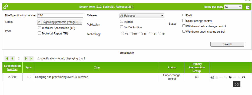
The last version was from 2006, in 3GPP release 6, which is two years before LTE was standardized in Release 8. The word LTE does not appear in the doc or in the metadata tags.
It speaks of TPF (Traffic Plane Function) and TPF (Charging Rules Function).
LTE is “Long Term Evolution” – In later releases this draft TPF would evolve into the PGW (before the PGW-C / PGW-U divorce) and the TPF would go on to become the PCRF (and save spring break).
Reading through these early specs is like looking at Homo Eructs (get your mind out of the gutter) and knowing it evolves into Homo Sapiens.
So what does Gx over Gy do? Well, the concept is pretty straightforward, rather than needing a Sy interface between the PCRF and OCS, you can provision policy rules from the OCS, rather than on the PCRF.
So what network functions should implement this standard? Well, the P-GW specs do not reference this as something that’s included in the P-GW, nor is it in the GGSN – This was a “gooch” spec between the hypothetical standards land and real world implementations.
So will we be implementing it? Probably not. But an interesting bit of archaeology and a look through the genealogy of 3GPP.
There’s a cool feature in PFCP that allows you to redirect traffic, which I’ve written about before.
But there’s a funky thing that’s left me scratching my head, in the Redirect information IE, you can set a SIP URI.
Snippet from TS 3GPP TS 29.244
That’d be great and all, but PFCP is all about packets not about calls.
So what’s the deal?
Had I uncovered some Machiavellian plot to move channel-associated-signaling onto PFCP instead of TDM links as God intended?
Well, no…
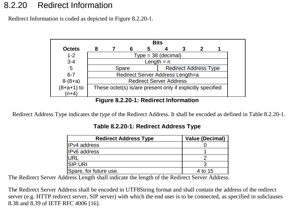
The Redirect Information in PFCP comes from the Redirect Information in Diameter, that’s how your OCS can tell your SMF or your PGW-C (or your TAS) – hey this session is all out of usage, and should be redirected.
Of course, PFCP is just all about packets, but Diameter has a foot in both camps, Gy and Ro are both on Diameter.
PFCP includes a “Redirect Information” IE, which if set, allows you to change the forwarding action in PFCP to Redirect traffic.
We use this for walled garden redirects, when the OCS reports credit exhausted to the PGW-C, the PGW-C can tell the UPF (PGW-U) that all the traffic from a given subscriber should be redirected to a captive portal / walled garden, like a “Topup Now Page” you’d be used to seeing on Airport WiFi.
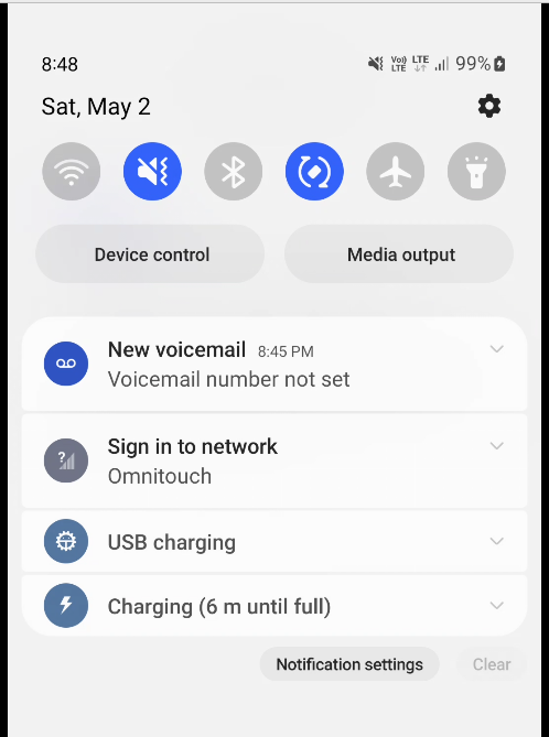
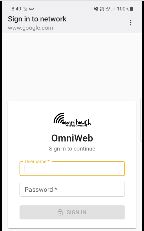
“Sign in to network” prompt presented on Cellular
Here’s what the spec says:
8.37. Redirect-Server AVP The Redirect-Server AVP (AVP Code 434) is of type Grouped and contains the address information of the redirect server (e.g., HTTP redirect server, SIP Server) with which the end user is to be connected when the account cannot cover the service cost. It MUST be present when the Final-Unit-Action AVP is set to REDIRECT. It is defined as follows (per the grouped-avp-def of RFC 3588 [DIAMBASE]): Redirect-Server ::= < AVP Header: 434 > { Redirect-Address-Type } { Redirect-Server-Address }
So how does this work in practice?
Once upon a time, you’d just intercept all HTTP request and serve your own content, but it’s not 2005 on Starbucks WiFi anymore, and SSL is everywhere.
Luckily this is a (mostly) solved problem, Apple has “Captive Network Assistant” that probes http://captive.apple.com/hotspot-detect.html and checks for a specific response, Google’s Android has http://connectivitycheck.gstatic.com/generate_204 and does the same thing.
But before I can tell you what we do, I’ll show you what we’re not doing before we do the doing so you can see what the do does by looking at what happens when we don’t – Clear?
Before we send any Session Modification Request with redirect I can do a DNS lookup, here’s an example from our test jig that goes to Facebook:
A Record lookup for facebook.com resolving to 57.145.8.1
This is just a regular A record DNS query wrapped up in GTP-U as it’d look from a eNB/gNB/SGW that gets an answer back also in GTP-U.
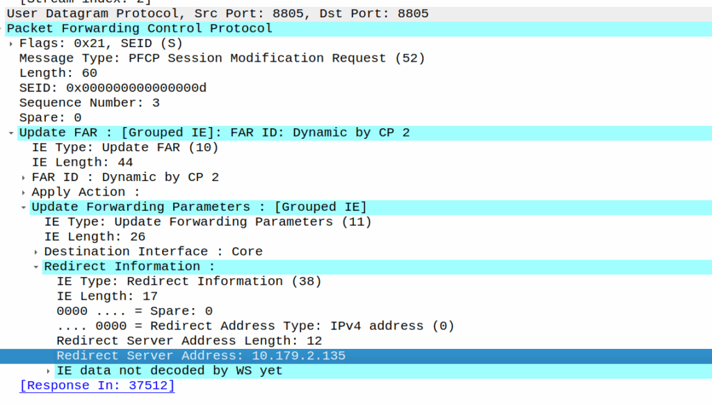
As we’ve already got a session up in our case, the SMF or PGW-C we sends the PFCP Session Modification Request I shared in the screenshot earlier to the UPF.
The Redirect Server Address in the Redirect Information IE in PFCP
We do a few things on the UPF at this point, the first, is that we block forwarding access to all IPs except 10.179.2.135 (The redirect server in the screenshot), and we steal / intercept all DNS queries.
This means if you query facebook.com after the Redirect Information is in place, you get back an A-Record answer for facebook.com but it’s telling you Facebook lives on our redirect server.
We’ve got a whitelist on our UPF for certain domains, so if we’re sending you to a self-signup page, you’re going to need to be able to hit our payment processors portals (Stripe, Paypal, etc), so we need to allow their domains, but we don’t know their IPs, so instead we do server side DNS lookups (via our DNS servers before you sneaky kids get any other ideas) for the whitelsited domains, and if it’s on our DNS whitelist, we allow resolution to those domains and allow access to those IPs returned in the DNS response.
In my lab I’m redirecting HTTP traffic to a management server
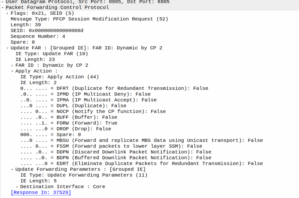
Turning it off just involves sending another PFCP Session Modification Request but without the redirect information.
We support a network in Alaska, and one of the guys we work with there – John – has a story (which I’ll steal here) where he gets a phone call late at night from someone saying they’re in the US Air Force, and uh, they’ve, uh, lost a plane. And since John works for the phone company, he wouldn’t have any idea where it is would you? They ask him.
As a matter of fact, John could see the last cell the SIM the pilot was carrying was attached to, they sent a helicopter out and found the pilot, who survived.
This was a long time ago, and he was able to pin the location down to a cell (sector), and lookup which direction the sectors were pointing for that cell and the location of it, to give a pretty good idea of the general search area.
Now that everyone carries a GPS in their pockets, the level of accuracy here is a lot more than just which cell are you served by (although that’s a lot of accuracy anyway, and not to be ignored).
There’s significant privacy implications here and a lot of misinformation about pinging cell towers and “zoom enhance” stuff.
I figured I’d actually share how this works IRL – There’s nothing ‘secret‘ here – All of this stuff is in the 3GPP standards which outline how mobile networks should behave.
There’s roughly 4 levels of accuracy in cell phone networks, we’ll cover each one, and how the network treats it.
(I’m talking 4G/5G here as most of the world has moved on or is already moving on from 2G/3G)
Tracking Area Level Accuracy
Cell sites get grouped into tracking areas, they’re kinda like broadcast domains in TCP/IP networking, when you need to “page” (find) a phone that’s “idle” (sleeping) you page the tracking area.
Tracking Area sizing has sweet spots, you want more than a few cells, commonly about a dozen or so in the same geographic area get lumped into the same tracking area. In regional areas you might have a large geographic area – Up to a few hundred Km in regional Australia for example, lumped into a single tracking area, whereas in a city that might be a single city block.
If you move between cells inside the same tracking area, then your phone doesn’t need to say to the network “hey I’m moving cells” – It’s only if we go over to a new tracking area that the phone needs to wake up and tell the network it’s now in this new tracking area.
(If you’ve got a tracking area that’s too big (too many cells) then it becomes a nightmare to find who you’re looking for, as the paging channels are always blaring out IDs, tracking areas too small and you’ve got phones having to constantly say “hey I’m moving to this tracking area now” – If you want to learn more about Tracking Areas I’ve written about them on the blog before)
The core network (MME/AMF) always knows the location of a phone at minimum to the tracking area – It’s the base level of location the network has to work with.
Cell ID Level Accuracy (CGI / E-CGI)
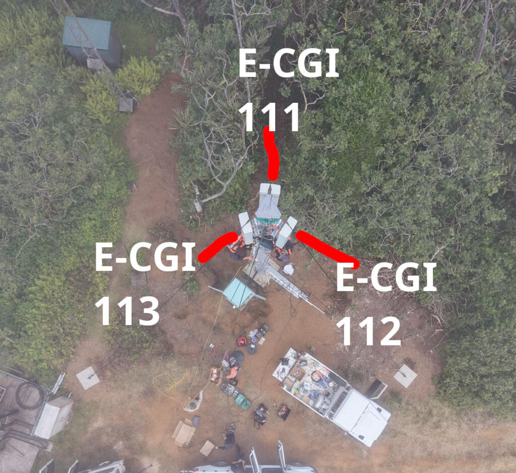
Every cell site sector (cell) has a unique ID to denote which carrier you’re connected to. If you’ve got a 3 sector site, with a single layer per cell sector, then that’s 3 Cell Global Identifiers (CGIs) – one for each sector.
Here’s a tower we put up recently, the CGIs I’ve drawn on are just examples, but if you’re connected to the sector facing North, you’d have CGI of 111, if you’re connected to the cell to the south east, you’d have 112, and the one to the south west would be 113.
CGIs are just numbers, they could be any number, all that matters is that number is unique (ish) in the network, they don’t need to be sequential, or have any common digits.
If we know the CGI of a given user we can kinda draw a 1/3rd wedge off the side of the tower in the direction the antenna is pointing, and if you’re inside that wedge, and that tower is still providing coverage, then we know the customer is somewhere inside that wedge.
But those wedges can still be large, so the margin of error for locating someone is still pretty large. You can probably answer the question of “Are they in the office or are they at home” if they’re in different suburbs.
When the network wants to know a bit more about where the phone is located, it can ask the cell site which Global Cell ID the phone is in, this is pretty rare, but can be done. When the phone is actively doing stuff, like making a call, using data or sending a text, the network knows the CGI of the event.
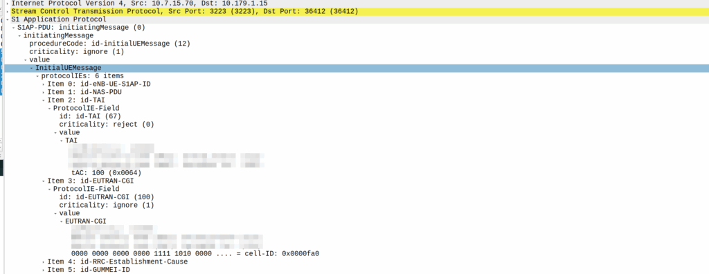
My lab is setup with CGI 4000 and TAC 100, and this information is littered across every signaling message.
Initial Attach message
Note: The encoding shows up as 0000 0000 0000 0000 1111 1010 0000 …. = cell-ID: 0x0000fa0 for CGI 4000, just roll with it, the spec explains why this is.
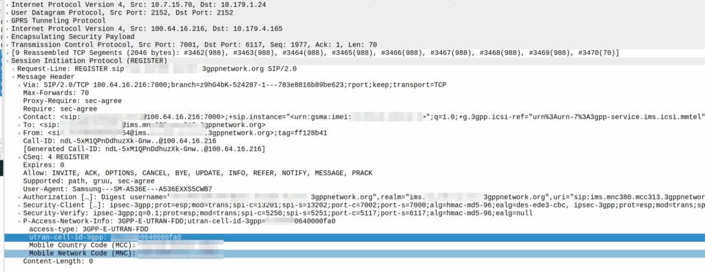
A SIP REGISTER message from my lab, showing the CGI (00640000fa0)
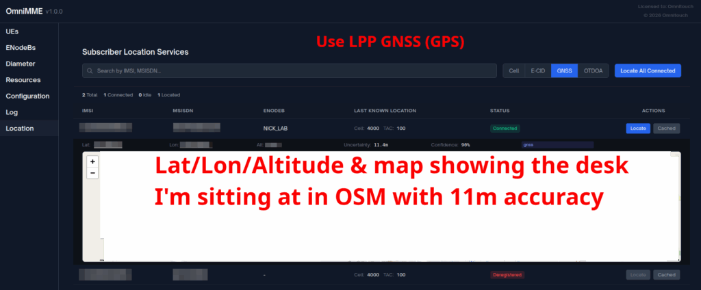
GNSS LPP Positioning
When the Cell ID level is not accurate enough, the network can request the phone to provide it’s location, using whatever it’s got available to it.
In reality, this is either done by an engineer from the phone company with the permissions to do so, or directly by law enforcement using the SLh/SLg Diameter interfaces.
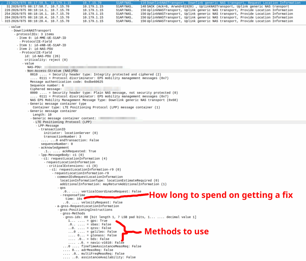
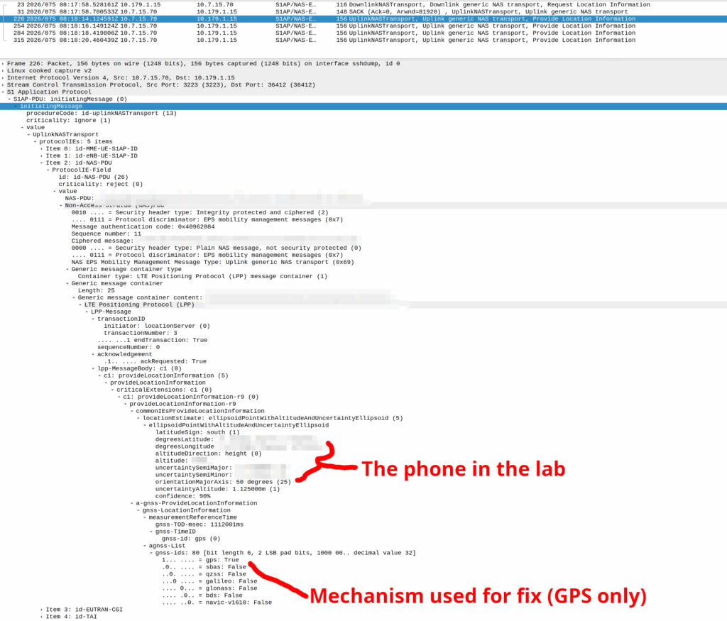
When an engineer does it, there’s usually a portal they can go to, like this one in OmniMME, they search the IMSI or MSISDN, and then can get the location information via a variety of methods.
Your phone gets a message from the network, that says “Hey phone, tell me where you are”.
If you’ve got enough access to the baseband you can even block these requests should you feel so inclined.
I’ve included some Wireshark captures of how this actually looks and how it looks from the Web UI of the MME, with the address removed.
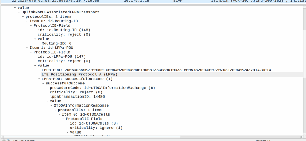
OTDOA – “Pinging”
Sometimes you don’t get an indoor location with GPS or the phone might be too old to support LPP Positioning, no GPS built in or something.
In those scenarios, we use “Time Difference of Arrival” to calculate the position by measuring time between 2 or more cell sites, and calculating the time between when a signal was sent to a phone, and when it receives it, to calculate distance from the base station.
This is better than CGI as it gives you an idea of how far from the cell site the phone is, and the cell site, but it doesn’t return a map with “you are here”, but rather some rough distances, and CGIs for each cell it can see.
The engineer then pulls up a map of all the cell sites, finds the CGIs the cell phone can see, headings for each CGI and tries to do some early high school maths like someones life actually depends on it.
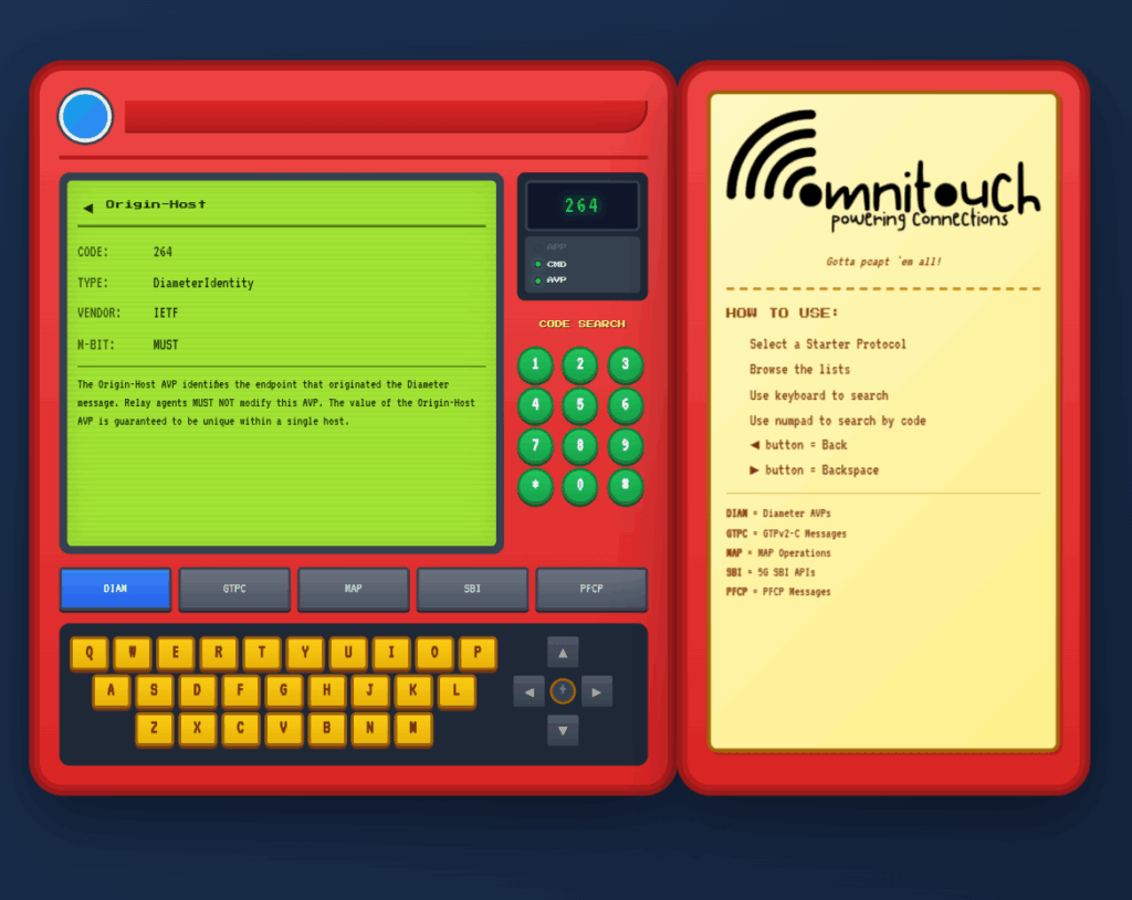
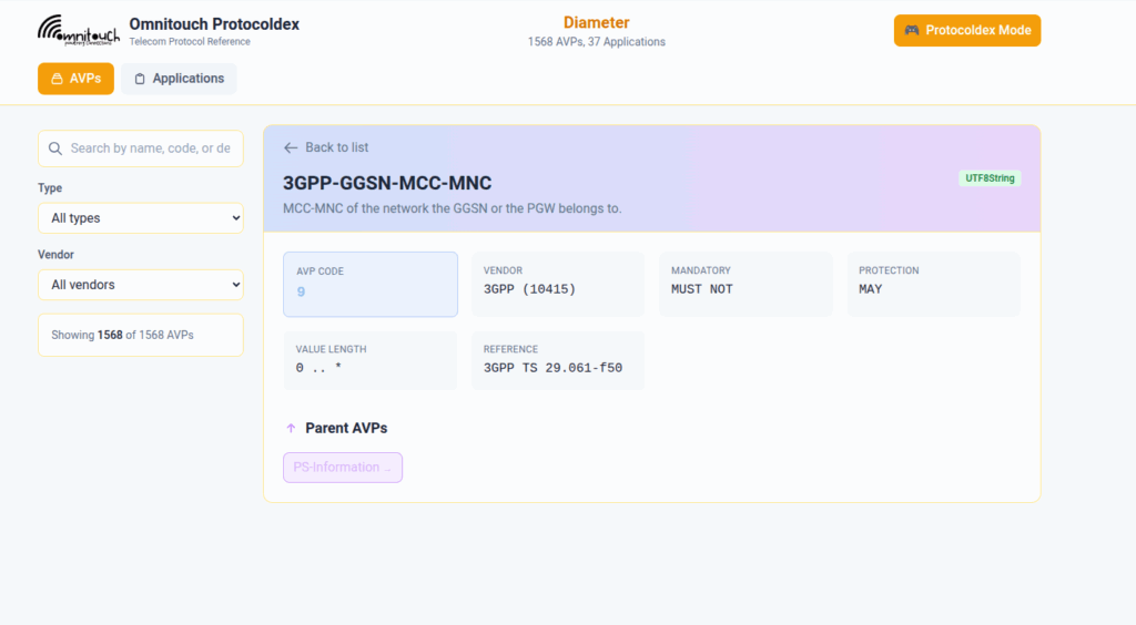
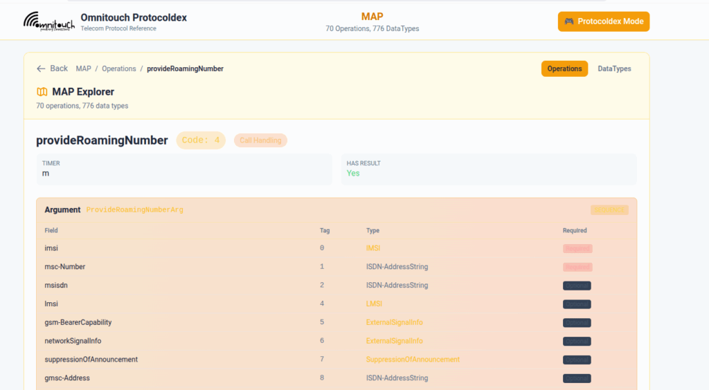
I do a lot of protocol testing, writing Diameter/PFCP/GTP-C etc, and spend a lot of time referencing the standards.
So I built this – Inspired by a 1990s video game / TV / Playing card franchise online reference tool, but rather than identifying pocket monsters, it’s identifying AVPs and stuff
You can punch in the AVP code, AVP name, description, etc, for Diameter, PFCP, GTP-C, MAP or SBI and see all the details to go with it.
I’ve been using it a heap, hopefully some of you might find it useful:
One of our customers is an MVNE and they reached out the other day with an issue.
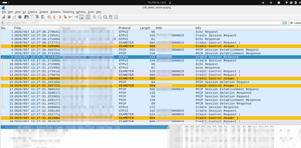
They were turning up a new PGW and they’d see Create Session Request, everything looked OK, it’d get a response, but then in the GUI of the PGW-C they’d see the session drop.
The logs showed the newly setup session dropping shortly after being setup.
Have a look at the screenshot and see if you can work out why:
So what’s going on, and why is the PGW-C deleting sessions?
The initial reaction from the customer was there’s something up with the PGW, but the answer is bit more nuanced.
Per the specs, you can’t have two PDN sessions for the same subscriber (IMSI) on the same APN (DNN).
So if 50557000000001 is connected to the PGW-C on the internet APN, if I send another Create Session Request to the same PGW-C, it deletes the old session, before starting the new one.
In this case, the MVNE it was going through was dropping the Create Session Response, so it never made it back to the MNO, and then the MME in the MNO sent it again.
Joys of GTPv2-C being UDP based and connectionless!
When a UE enters Idle mode, the network releases radio resources and the UE enters power saving mode.
When the UE wants to send data (Uplink) the UE just tells the network “hey I want to send something” and away it goes, nice and simple.
But when the network wants to send data to the UE (Downlink) then the UPF needs a method to tell the Control Plane (SGW-C or SMF) that there’s data waiting and to go and page the UE.
A prime example of this is when you’ve got a Mobile Terminated VoLTE call coming in, you need a way to tell the UE to wake up out of Idle mode because you’ve got something to send to it (a SIP INVITE).
But in order for this to work, we can’t just say “Hey I’ve got some packets for you” and let them get dropped, the UPF also needs to buffer (store temporarily) the downlink packets for the UE until the UE comes out of Idle mode, and then flush them out to deliver them to the UE.
So let’s look at the flow.
Enabling Buffering (Idle Mode)
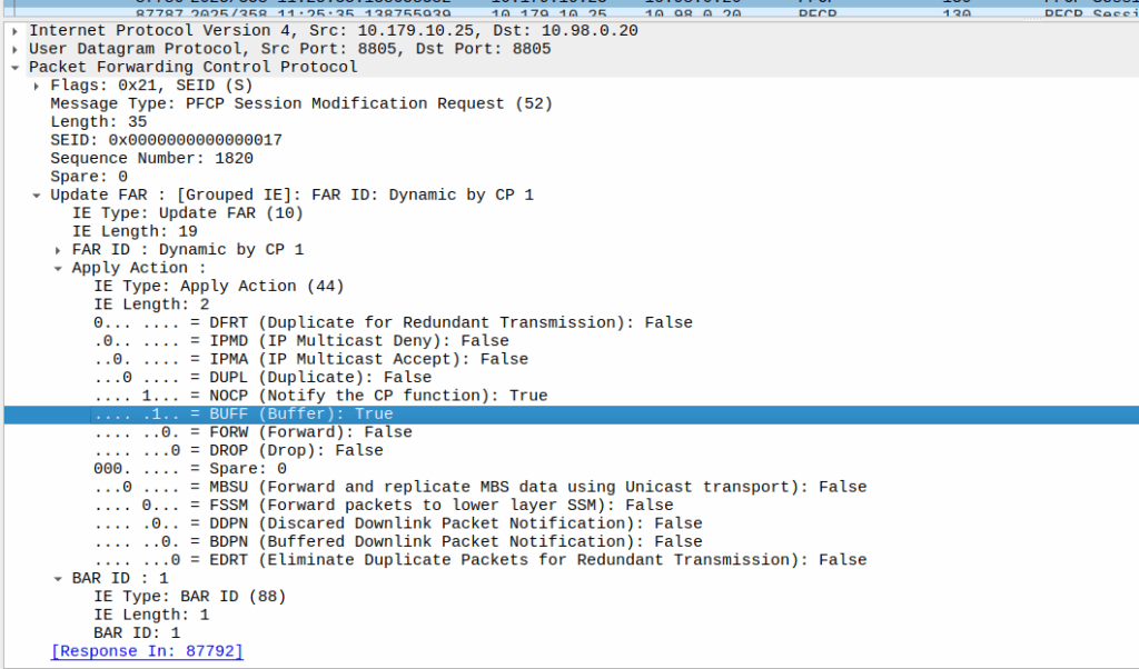
When the sub enters idle mode, the Control Plane (SGW-C for an EPC or SMF for a 5GC) it sends a Session Modification Request but with the BUFF (Buffer) and NOCP (Notify Control Plane) flags set, and FORW (Forward) turned off.
What this means is now for packets to that bearer, the UPF must:
Not forward any traffic
Buffer the traffic
Notify the control plane when the first packet comes in that we buffer
Then the UPF just sits and waits for any incoming packets.
The Notify
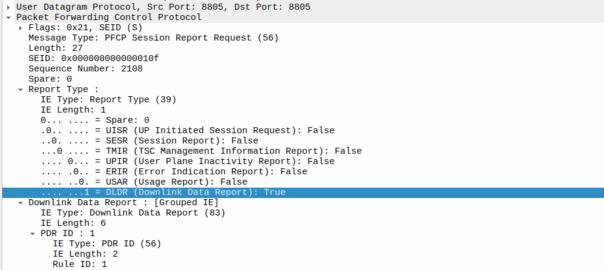
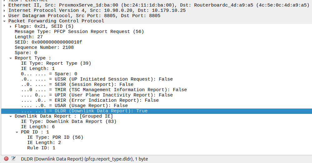
When the UE gets an incoming packet that it’s supposed to buffer and notify, well, it does just that.
The packets are copied into a buffer, in sequence, and for the first packet, the UPF must send a notification to the Control Plane.
That looks like this, it’s just a Session Report Request with the Dowlink Data Report flag.
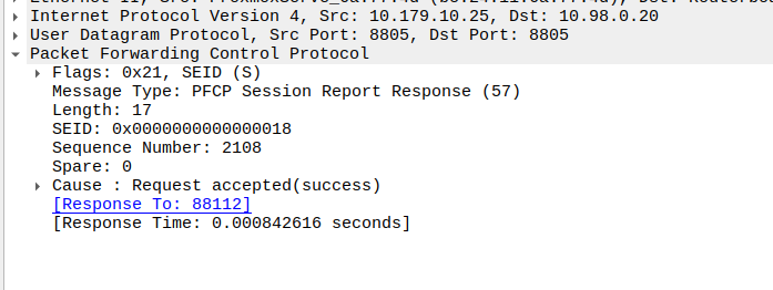
Now the SMF/SGW-U sends back a Session Report Response and starts the process of paging the UE.
At the same time the UPF keeps buffering – It’s work is not done.
Flushing and Forwarding
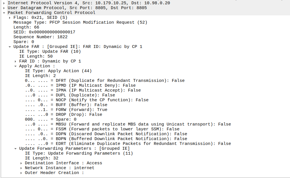
Once the UE has become reachable, the Control Panel needs to modify the bearer to turn back on forwarding. It does through another Session Modification Request, this is the inverse of the one it sent to turn on buffering, as we’re turning off buffering and notifications, and turning on forwarding.
Now the UPF flushes it’s buffer – It’ll send all the packets that were queued up out over the wire towards the gNB / eNodeB, so the SIP INVITE for the MT call or whatever will make it through.
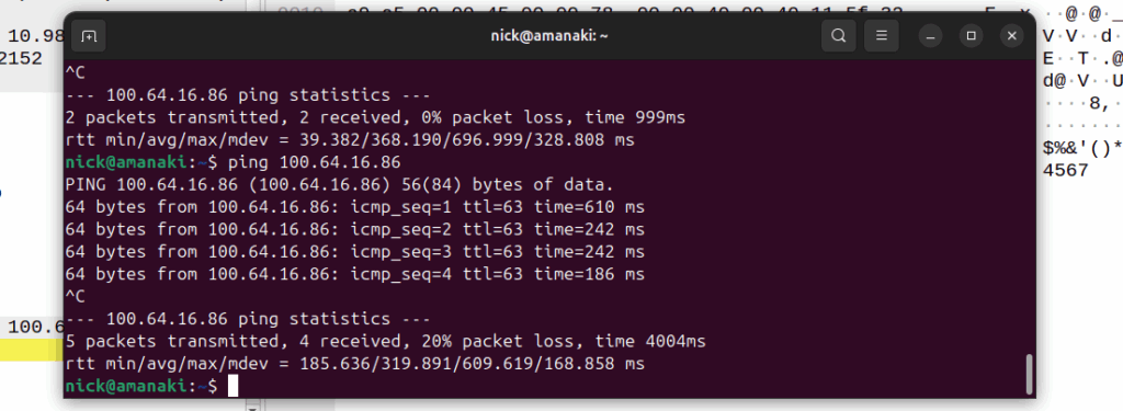
One thing to note is that the packets that get buffered are going to take some time to get delivered, as the NOTIFY / page UE / reconnect UE / Session Modification Request (to enable forwarding again) needs to happen before the buffers are flushed and delivered.
Notice the latency spike on the first packet? 610ms? That’s because the UE had to be paged to wake up.
And that’s pretty much it, the UPF has now flushed it’s buffers and moves back to forwarding actions.
Our team recently shipped a new UPF which is a huge improvement on our old UPF, and I drew the short straw of doing all the interop testing for the IMS.
Initially I thought there was an issue with IP routing, as I’d never see the SIP register from the UE, but I would see the IMS APN coming up.
I could access the internet from the UE IPs just fine, but that’s going to public IPs, whereas the P-CSCF is in private address space, and hosted on the same box as the UPF.
I spent hours on this as my lab servers do routing on a stick, and I thought some hardware offload somewhere was trying to fast path my packets and send them back to the server without going via the router.
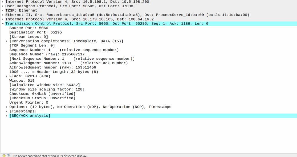
Then I dug a little deeper and found I could see the 3 way handhake between the UE an the P-CSCF, but no SIP packets.
Successful 3 way handshake between the UE and the P-CSCF on TCP 5060
This was confusing, clearly we had at least intermittent two way comms – the 3 way TCP handshake confirmed that, but then why were packets not getting across?
We have an XCAP server hosted on our P-CSCF instances, so I tried hitting that from the phone in case there was something weird about routing to the network segment that hosts the P-CSCF, but I could hit the XCAP server just fine, so now I was certain the UE IP pool could route to the P-CSCF and 3 way handshake for TCP was working and payload could be pushed.
Clearly we can route to the P-CSCF as that’s where this XCAP server is hosted
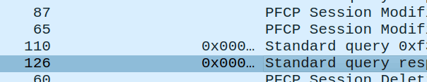
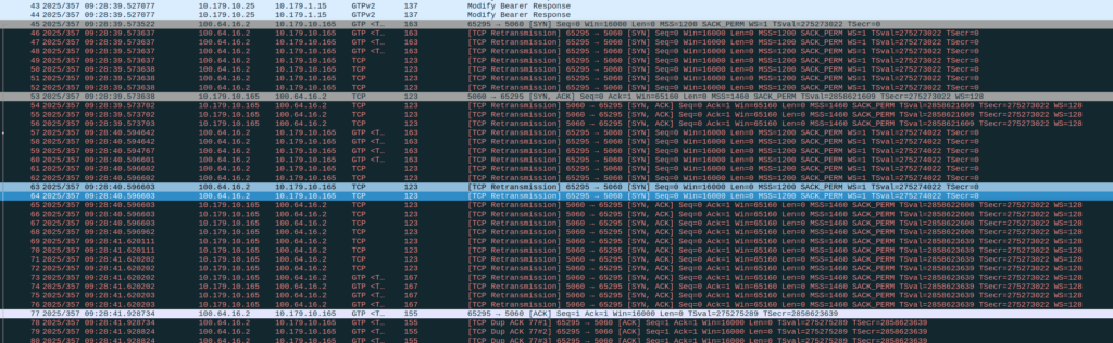
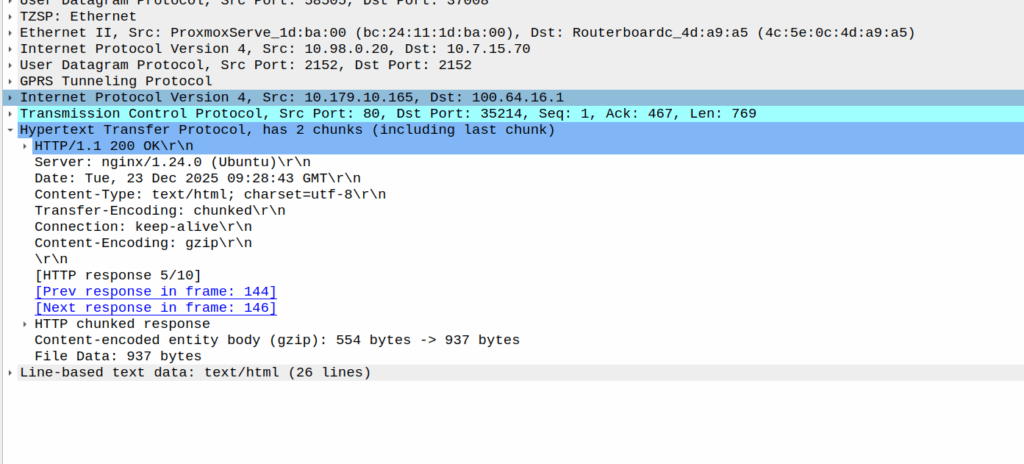
Then I dug into what happened after the 3 way handshake, and I found a TCP payload containing the start of the SIP REGISTER.
Hmm, we have a SIP Fragment here at least…
I traced it all the way through and lo, it’s hitting the P-CSCF:
And the fragment is recieved on the P-CSCF
Okay, but then what happens, because it’s only a fragment, not the complete re-assembled packet, so what’s going on?
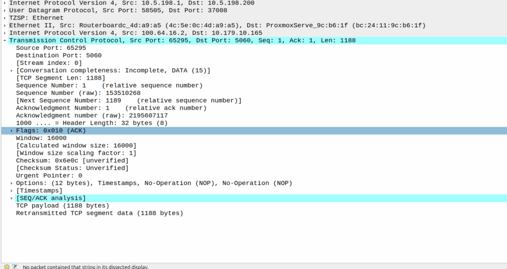
Well, the P-CSCF sends a TCP ACK back to the UE.
And the TCP fragment containing the first part of the REGISTER gets an ACK back from the P-CSCF
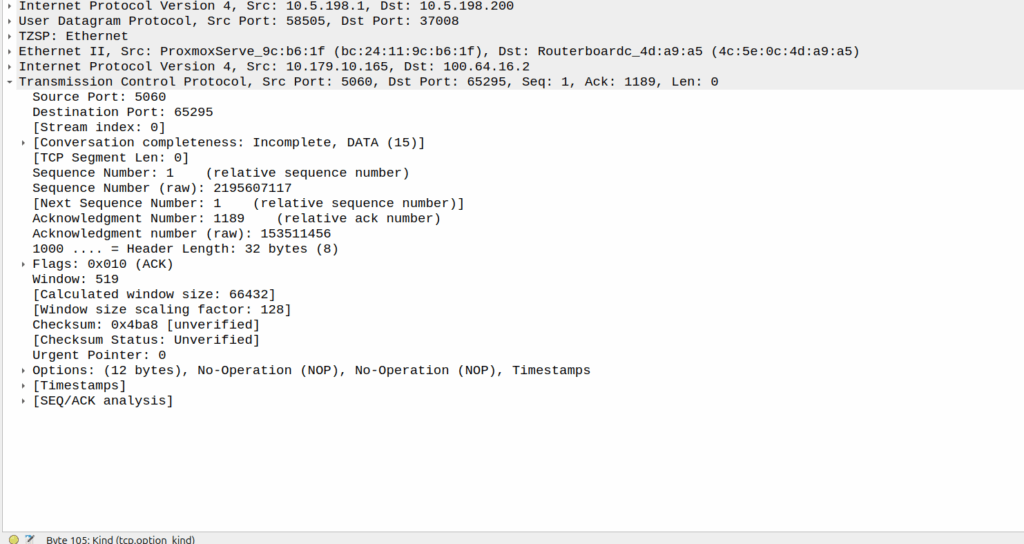
The ACK gets forwarded to the UPF:
And that TCP ack makes it to the P-CSCF
And then… Nothing? The UPF never encaps the TCP ACK back into GTP-U and never sends it onto base station.
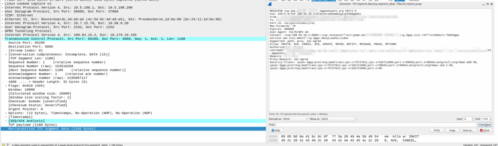
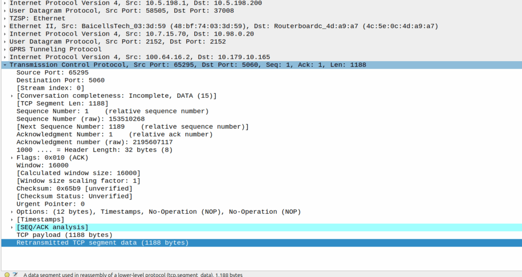
Eventually the UE re-sends the payload with the start of the REGISTER, but it does not get the ACK from the P-CSCF.
Retransmitted TCP segment containing the REGISTER from the UE
So naughty UPF right? Not forwarding that ACK for some reason?
I started digging, maybe the ACK was getting routed weirdly and landing on the UPF without going through the router?
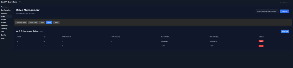
Well not quite…
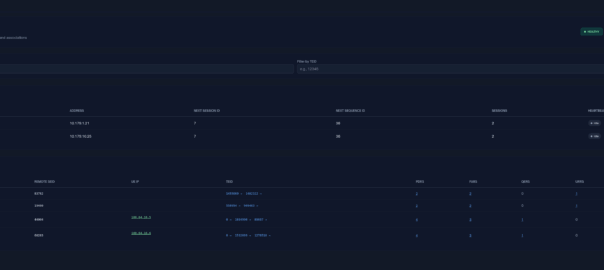
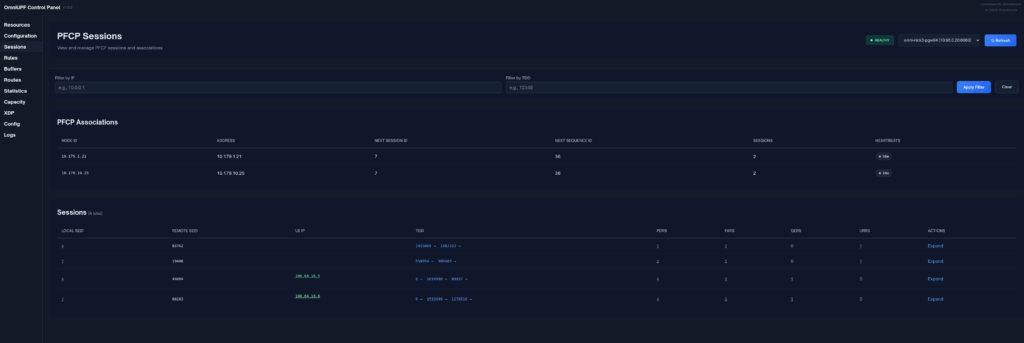
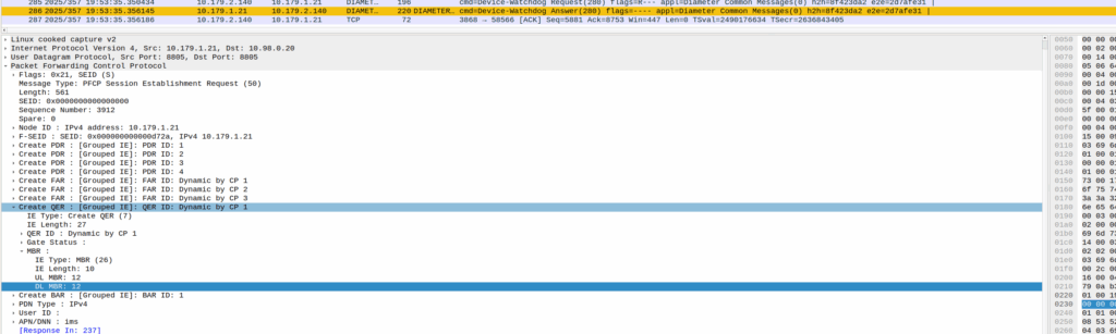
When I started digging into the QER rules being installed I noticed the MBR bitrate we had on the IMS APN in the HSS was tiny.
The UPF can only gate on traffic to the UE, so was gating the ACK traffic, as the QER had consumed all the bandwidth so the ACK never made it back.
Time wasted – About 4 hours, but I will not make this mistake again!
A concept that’s always been a bit unclear to me was how the Sh Profile, XCAP data for call forwarding / barring and RepositoryData all fit together.
Let’s start off with the basics.
The Diameter Sh interface sits between an Application Server (Typically TAS, SMSc, XCAP server, etc) and the HSS.
This AS can run a Diameter User Data Request to get the contents of Sh Data, which is returned in the User Data AVP (702) for a given subscriber.
Application Servers can also subscribe to be notified of changes in the Sh data on the HSS, by sending a Subscriber Notification Request, and when the data changes they’ll get a “Push Notification Request” to inform them of the change.
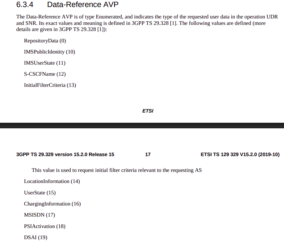
When sending this User Data Request the AS can specify what data it wants to get returned, for example an AS might want to know the current S-CSCF of a given subscriber, in which case, the AS would set the DataReference AVP (703) to 12 for S-CSCFName.
Not the complete list…
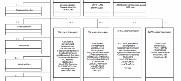
The the AS can request can be public and private identities (IMSIs and MSISDNs), location in the PS and CS networks, TADS info, SRVCC parameters, etc, etc.
Data like TADS Info, CS and PS network location, Public and Private identities, come from the HSS and cannot be modified, these values either come from the static subscriber definition in the HSS (what was set when provisioning the subscriber), or based on the subscriber’s state (ie where they’re registered on the network).
RepositoryData
But there is a section of data we can request the HSS return called RepositoryData which can be modified/updated by the end user or other applications in the network (Modified by ASes), via a Profile Update Request.
This data is where we put the call forwarding, call barring, caller ID presentation/restriction info – The HSS doesn’t really care what is stored in RepositoryData, it’s just a transparent place to store this data.
Think of it as a simple folder containing text files, each text file has a name (ServiceNotification) which allows us to reference the blobs of data by name, a SequenceNumber to identify duplicates, and then the actual contents of the file itself ServiceData.
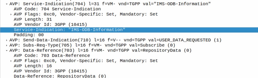
We can then request the contents of these files from the HSS by calling DataReference of RepositoryData and setting the ServiceIndication to be the “file” we want returned to the AS by the HSS.
For example, if the Data-Reference AVP is set to zero (Repository Data) and the Service-Indicator AVP is set to “IMS-ODB-Information” the HSS will return the data for the file IMS-ODB-Information of repository data.
This RepositoryData is just “transparent” storage of XML data by the HSS, and this is where we’d put Call Forwarding, Operator Defined Barring and CLI presentation/restriction parameters.
In theory you could also store 3rd party custom unstructured data here (Move over AWS S3 buckets, I’m moving all my storage to Diameter!), but it’s not commonly used beyond call routing parameters.
The two most common types of ServiceIndication keys you’ll see stored in RepositoryData are MMTEL-Services and IMS-ODB-Information. Each of these are defined by their own XML spec, but the MMTel-Services key is where all of our Call Forwarding, Caller ID Presentation/Restriction parameters live, while IMS-ODB-Information contains the parameters for Operator Defined barring – Both of these XML definitions we’ll dive into in a post of their own, but for now all you need to remember is that they’re stored transparently as XML on the HSS.
An example use case of this would be when a user wants to manage their call forwarding data via XCAP. When the user pulls up the Call Forwarding menu on their phone, the first entry point will be the XCAP Server (AS) to get all the User Data for MMTelServices, so it’ll do that via a Diameter User Data Request with the DataReference set to RepositoryData and the ServiceIndication set to MMTel-Service so the XCAP server can pass the full XCAP XML body to the UE.
The UE can then update this data, and the XCAP server just sends a Profile Update Request to push the updated XML to be stored on the HSS.
Fitting this all Together
Data sent to the AS by the HSS will always include the <Sh-Data> XML, but the child keys within it depend on the data the AS requested under the Data-Reference.
If we requested IMSI as the DataReference, then the returned XML might look like:
<Sh-Data>
 <imsi>9990112345677</imsi>
</Sh-Data>
Likewise, if you requested IMSPublicIdentity as the DataReference you’d get:
The spec goes into full detail on all the possible keys, but in short, when the AS queries the data for the provided DataReference, the HSS sends back an Sh-Data XML body containing at a minimum those keys.
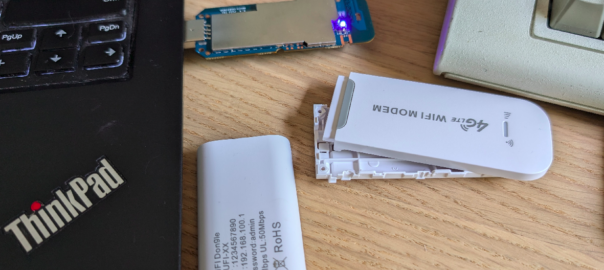
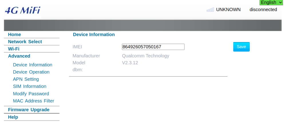
The device showed up as an rndis_host adapter in Linux, just like a USB NIC, and browsing to the default gateway shows a web UI where amazingly, you can set the IMEI – Pretty sure this isn’t legal…
This is not the IMEI it came with – that’s the IMEI of a EP06-e chip on my desk…
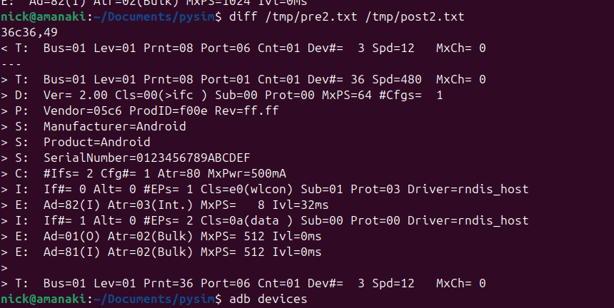
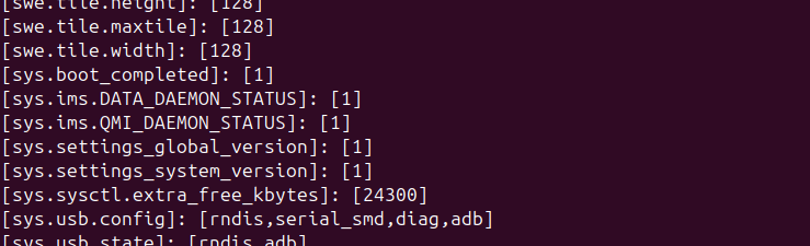
Oddly I could see it was an Android device, but with no adb port exposed, but wait – does that mean this an Android phone in a USB stick?
Alas no DIAG mode serial adapter showed up, despite a few variations on the above.
So with ADB connected could I stream the video from the device and use it like an Android phone?
You betcha:
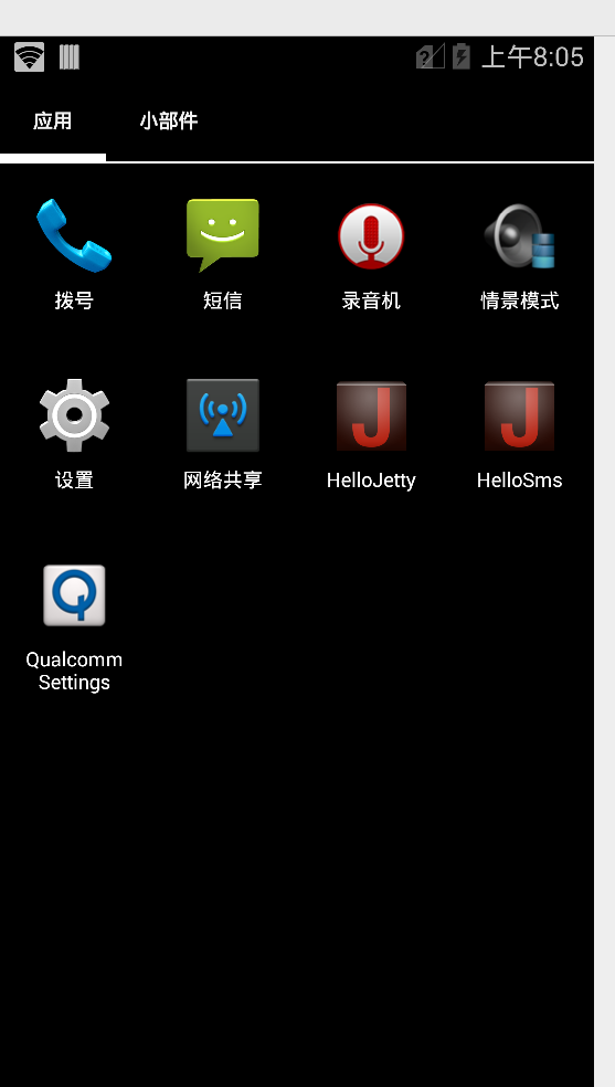
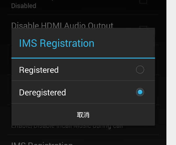
After poking around in Android I found an App called “Qualcomm Settings” which piqued my interest.
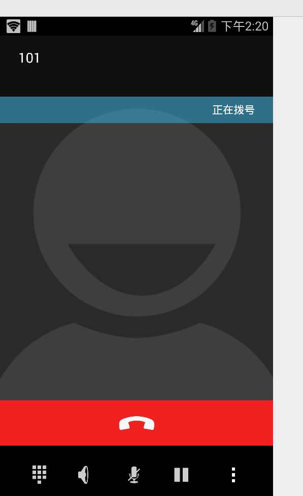
Alas the unit only supports LTE Band 1 / 3 / 5 none of which I have in my office (I’m too lazy to go out to the lab to fire up an Airscale) so I put a public SIM in it and was able to use data, but when I tried to make a call it seems it kicked off CS fallback.
More exploring to do, but pretty amazing what $10 buys you!
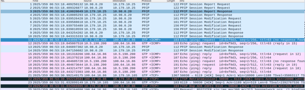
So we’ve found this scenario that occurs on some Samsung UEs, in certain radio contions, where midway through an otherwise normal voice call, the UE sends “mystery” data (Not IP data), which in turn causes the UPF to send the error indication and drop the bearer, which in turn drops the call.
The call starts, like any normal call, SIP REGISTER, INVITE, etc.
The P-CSCF / PCRF / PGW set up the dedicated bearer for the voice traffic, and the RTP stream starts flowing over it.
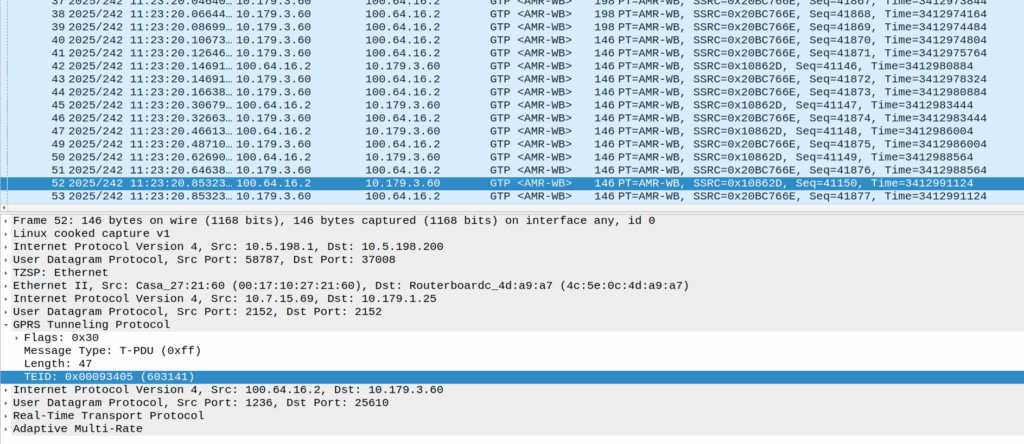
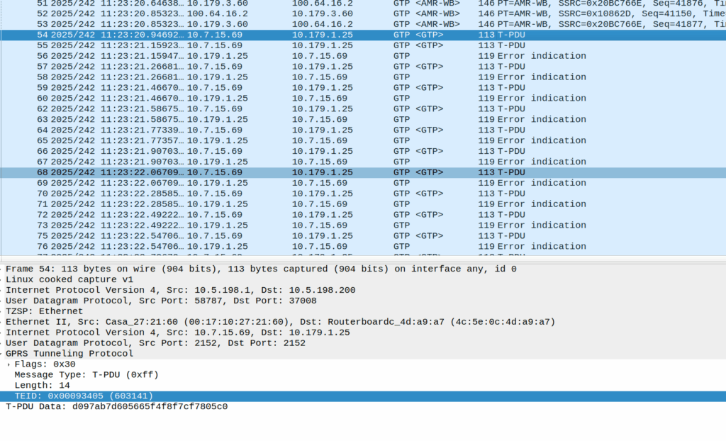
Then the UE sends these weird packets instead of the RTP stream:
These are GTP-U encapsulated data, with the TEID that matches the TEID used for the RTP stream, but there’s no IP data in them – they’re only 14 bytes long and sent by the UE.
Here’s some examples of what’s sent (each line is a packet):
An IPv4 header is 20 bytes long, and IPv6 header is 40, so this is too short for either of those protocols, but what else could it be?
There’s some commonality of course, starts d0 as the first octet, then d1, d2, d3, etc. So that’s something?
I thought perhaps it was a boundary issue, that the standard RTP packet was being split across multiple GTP-U payloads, but that doesn’t appear to be the case.
An Ethernet header is 14 bytes, but if we were to decode this as Ethernet there’s still nothing it’s transporting, and the destination MAC is changing sequentailly if that’s the case, which would be even weirder.
I also thought about RTP that for some reason has lost it’s IP/UDP header, as the sequentially counting byte at the start could be the RTP sequence number, but that’d be 19 bytes minimum and the sequence number is the 3rd and 4th byte, not the first.
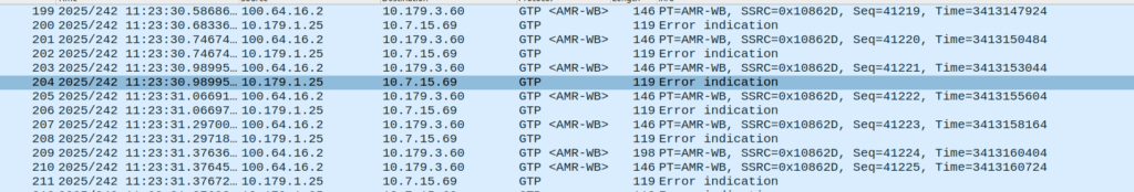
Whatever they contain, we see this sent over and over for a few seconds, then bam, back to normal RTP stream flowing.
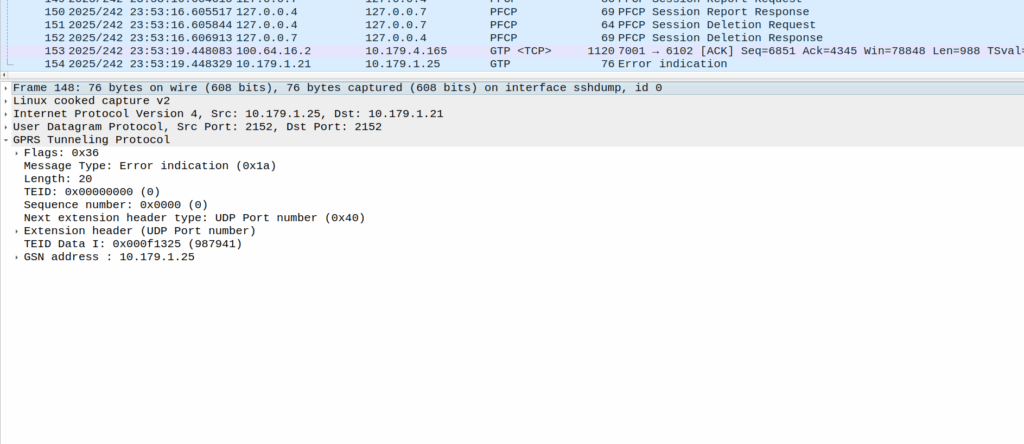
Or at least it should be, but the invalid packet causes the UPF to generate a GTP-U Error Indication.
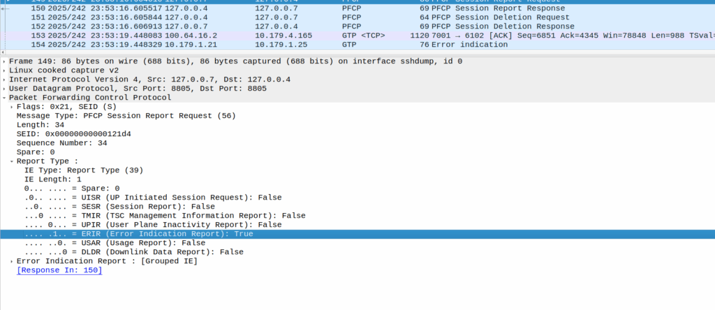
These Error Indication payloads eventually lead to the next PFCP Session Report Request having the Error Indication Report (ERIR) flag set to True.
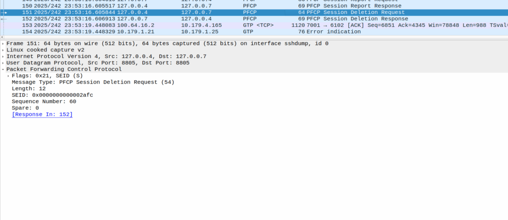
When the PGW-U gets this, it sends a Session Delete Request, which dutifully drops the bearer.
Meaning the session drops on the EPC side, and the RTP drops with it, eventually a BYE is sent from the phone due to RTP timeout.
The above screenshot shows a different cause of GTP-U Error Indication – At this point the bearer has been dropped on the EPC side and these are Error Indications to report it doesn’t know the TIED / bearer.
How to fix this?
Well, unlikely we’ll get a fix on the Samsung side, so we’ll need to not drop the bearer on the PGW-C if we get a lot of Error Indications, and hope for the best.
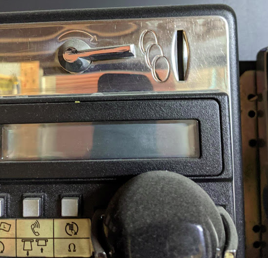
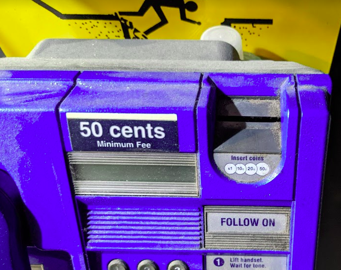
Let’s imagine the coin slot on a payphone – Coins can only enter the slot if they’re aligned with the slot.
If you tried to rotate the coin by 90 degrees, it wouldn’t fit it in the slot.
If the slot on the payphone went from up-to-down, our coin slot could be described as “vertically polarized”. Only coins in the vertically polarized orientation would fit.
Likewise, a payphone with the coin slot going side-to-side we could describe the coin slot as being “horizontally polarized”, meaning only coins that are horizontally polarized (on their side) would fit into the coin slot.
RF waves also have a polarization, like our coin slot.
A receiver wishing to receive into signals transmitted from a vertically-polarized antenna, will need to use a vertically-polarised antenna to pick up the signal.
Likewise a signal transmitted from a horizontally polarized antenna, would require a horizontally polarised antenna on the receiving side.
If there is a mismatch in polarization (for example RF waves transmitted from a horizontal polarized antenna but the receiver is using a vertically polarized antenna) the signal may still get through, but received signal strength would be severely degraded – in the order of 20dB, which is 1/100th of the power you’d get with the correct polarization.
You can think of polarization mismatches as like cutting up the coin to fit sideways through the coin slot – you’d get a sliver of the original coin that was cut up to fit. Much like you recieve a fraction of the original signal if your polarization doesn’t match on both ends.
Plagiarised diagram showing antenna polarization
Useless Information: In Australia country TV stations and metro TV stations sometimes transmitted different programming. To differentiate the signals on the receiver side, country TV transmitters used vertical polarisation, while metro transmitters used horizontal polarization. The use of different polarization orientation cuts down on interference in the border areas that sit in the footprint of the metro and country transmitters. This means as you drive through metro areas you’ll see all the yagi-antennas are horizontally oriented, while in country areas, they’re vertically oriented.
Vertical Polarization
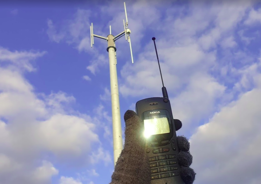
Early mobile phone networks used Vertical Polarization.
This means they used an flagpole like antenna that is vertically oriented (Omnidirectional antenna) on the base-station sites.
Oldschool mobile phones also had a little pop out omnidirectional antenna, which when you held the phone to your ear, would orient the antenna vertically.
This matches with the antenna on the base station, and away we go. You still sometimes see vertical polarization in use on base-station sites in low density areas, or small cells.
Vertically polarized mobile phone antenna, which is oriented vertically, like on the base station behind it.
Increasing subscriber demand meant that operators needed more capacity in the network, but spectrum is expensive. As we just saw a mismatch in polarization can lead to a huge reduction in power, and maybe we can use that to our advantage…
Shannon-Hartley Theorem
But first, we need to do some maths…
Stick with me, this won’t be that hard to understand I promise.
There are two factors that influence the capacity of a network, the Bandwidth of the Channel and the Signal-to-Noise Ratio.
So let’s look at what each of these terms mean.
Bandwidth
Bandwidth is the information carrying capacity. A one-page sheet of A4 at 12 point font, has a set bandwidth. There’s only so much text you can fit on one A4 sheet at that font size.
A4 Sheet, 12 point font, has 989 words.
We can increase the bandwidth two ways:
Option 1 to Increase Bandwidth: Get a larger transmission medium. Changing the size of the medium we’re working with, we can increase how much data we can transfer.
For this example we could get a bigger sheet of paper, for example an A3 sheet, or a billboard, will give us a lot more bandwidth (content carrying capability) than our sheet of A4.
Changing from an A4 sheet to an A3 sheet, increases the number of characters we can store on the page (Slightly more than doubling the bandwidth).
Option 2 to Increase Bandwidth: Use more efficient encoding As well as changing the size of the medium we are using, we can change how we store the data on the paper, for example, shrinking the font size to get more text in the same area, which also the bandwidth.
In communications networks this is also true: Bandwidth is determined by how much spectrum we have to work with (For example 10Mhz), and how we encode the data on that spectrum, ie morse-code, Binary-Phase-Shift-Keying or 16-QAM. Each of the different encoding schemes have different levels of bandwidth for the same amount of spectrum used, and we’ll cover those in more detail in the future.
So now we’ve covered increasing the bandwidth, now let’s talk about the other factor:
Signal-to-Noise Ratio
Signal-to-NoiseRatio (SNR) is the ratio of good signal, to the background noise.
On the train my headphones on block out most of the other sounds. In this scenario, the signal (the podcast I’m listening to on the headphones) is quite high, compared to the noise (unwanted sounds of other people on the train), so I have a good Signal-to-Noise ratio.
When we talk about the Signal-to-Noise Ratio, we’re talking about the ratio of the signal we want (podcast) to the noise (signal we don’t want).
When I’m on the train if 90% of what I hear is the podcast I’m listening to (the “signal”) and 10% is random background sounds (the “noise”) then my signal-to-noise-ratio is really good (high).
Capacity and SNR
Let’s continue with the listening to a podcast analogy.
The average human talks about 150 words per minute. So let’s imagine I’m listening to a podcast at 150 words per minute.
If I’m listening in an anechoic chamber, then I’ll be able to hear everything that’s being said, so my bandwidth will 150 words per minute. As there is no background noise, my capacity will also be 150 words per minute.
But if I leave an anechoic chamber (much as I love spending time in anechoic chambers), and go back on the train, I won’t hear the full 150 words per minute (bandwidth) due to the noise on the train drowning out some of the signal (podcast).
The Shannon-Hartley Theorem, states that the capacity is equal to the bandwidth multiplied by the signal to noise ratio.
So on the train hearing 90% of what’s said on the podcast, 10% drowned out, means my signal-to-noise ratio is 0.9 (pretty good).
So according to Shannon-Hartley Theorem the capacity of me listening to a podcast on the train (150 words per minute of bandwidth multiplied by 0.9 Signal-to-Noise Ratio) would give me 135 words per minute of capacity.
Claude Shannon, of 1/2 of the Shannon-Hartley Theorem, with an electromechanical mouse maze.
How this applies to RF Networks
In an RF context, our Bandwidth has a fixed information carrying capacity, for example on LTE, with a 5Mhz wide channel using 16QAM has 12.5Mbps of bandwidth available.
In a simple system, we have two levers we can pull to increase the bandwidth:
Increasing the size of the channel – If we went from a 5Mhz wide channel to a 20Mhz channel, this would give us 4x the available Bandwidth (Actually slightly more in LTE, but whatever)
Changing the encoding to cram more data on the same a size channel (From 16QAM to 64QAM would also give us 4x the available Bandwidth).
As we’ll see later in this post, there are some extra tricks (MIMO and Diversity) that we’ll look at later in this post, to increase the bandwidth of the system.
Our Signal-To-Noise (SNR) is constantly variable with a gazillion things that can influence the result. Some of the key factors that impact the SNR are the distance from the transmitter to the receiver and anything blocking the path between them (trees, buildings, mountains, etc), but there’s so many other factors that go into this. From atmospheric conditions, flat surfaces the signal can reflect off leading to multipath noise, other nearby transmitters, etc, can all influence our SNR.
Our capacity is equal to our Bandwidth multiplied by the Signal-to-Noise ratio.
Shannon-Hartley Theorem (ish)
As a goal we want capacity, and in an ideal world, our capacity would be equal to our bandwidth, but all that noise sneaks in and reduces our available capacity, based on the current SNR value.
So now we want to get more capacity out of the network, because everyone always wants to add capacity to networks.
One trick that we can use it to use multiple antennas with different polarization.
If our transmitter sends the same signal data out multiple antennas, with some clever processing on the transmitter and the receiver, we use this to maximize the received SNR. This is called Transmit Diversity and Receive Diversity and it’s a form of black magic.
The Transmitter uses feedback from the receiver to determine what the channel conditions are like, and then before transmitting the next block of data, compensates for the channel conditions experienced by the receiver, this increases the SNR and allows for higher MCS / encoding schemes, which in turns means higher throughput.
You’ll notice on most Antennas in the wild today you’ve got at least two ports for each frequency, which are + and -, which are the two polarizations.
Modern mobile networks use ±45° slant polarization (aka X Polarization), which works better in the orientations end users hold their phones in.
These two polarizations, each connected to a distinct transmit/receive path on the phone (UE) end and on the base station end, allows multiple data streams to be sent at the same time (spatial multiplexing, the foundation for MIMO) which enables higher throughput or can be configured enable redundancy in the transmission to better pick up weak signals (Diversity).
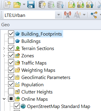
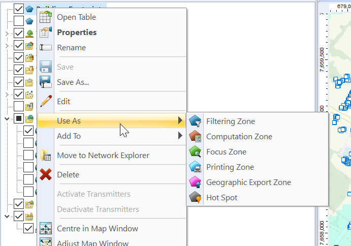
Having building footprints inside Atoll is super-duper valuable, this means you can calculate your percentage of homes / buildings covered, after all geographic coverage and population coverage are two very different things.
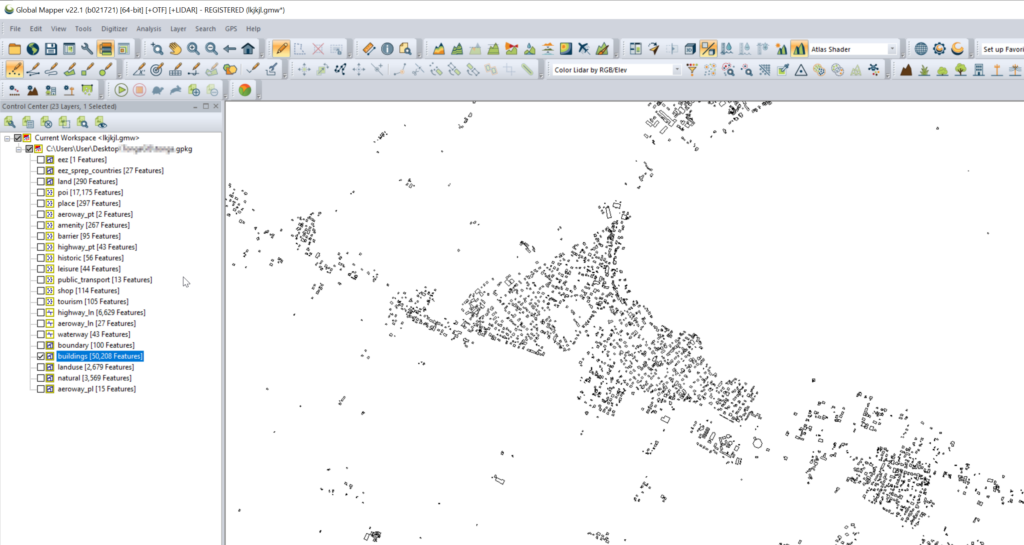
Once you’ve got the export, we’ll load the .gpkg file (or files) into GlobalMapper
Select one layer at a time that you want to export into Atoll. (This also works for roads, geographic boundaries, POIs, etc)
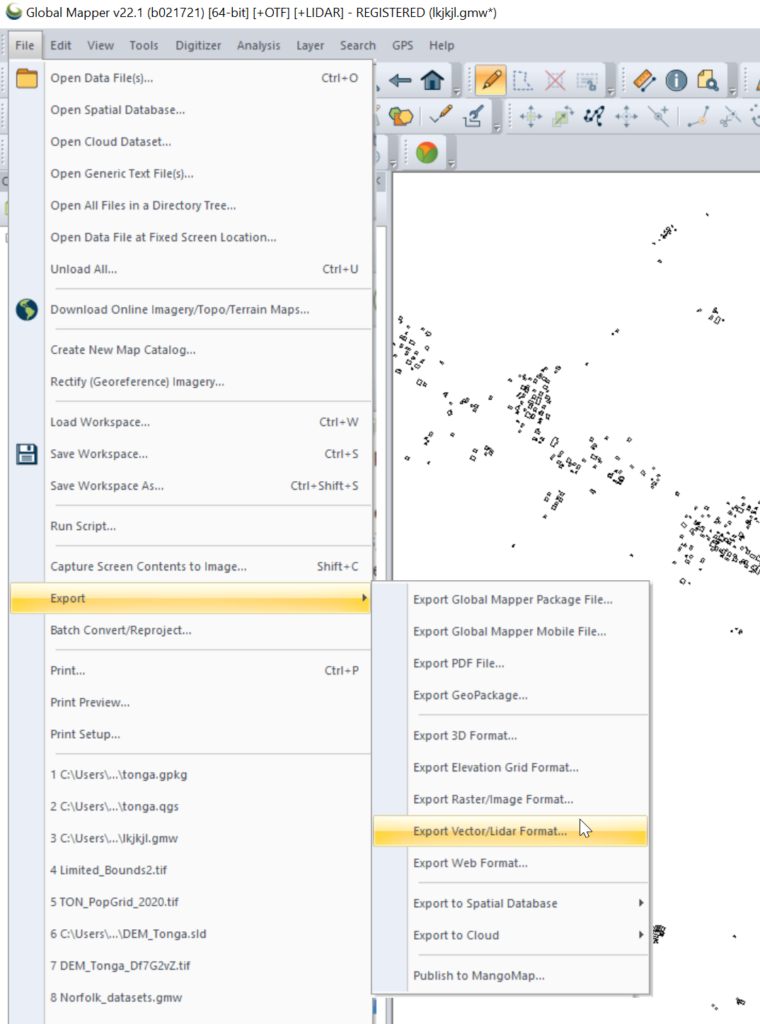
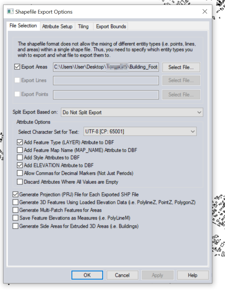
Export the selected layer from Export -> Export Vector / Lidar Format
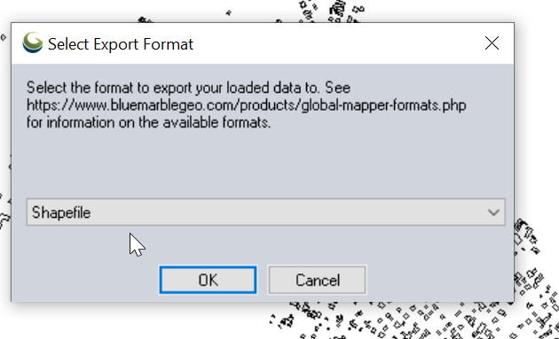
Set output type to “Shapefile”
Set output filename in “Export Areas” (This will be the output file). If you want to limit the export to a given area you can do that in Export Bounds.
Now we can import this data into Atoll.
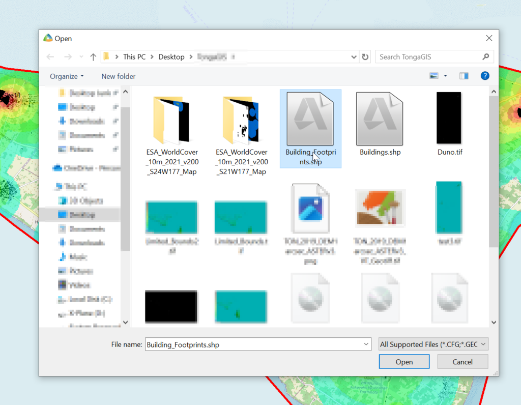
File -> Import
Select the exported Shapefile we just created.
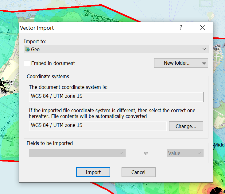
Set the projection and import
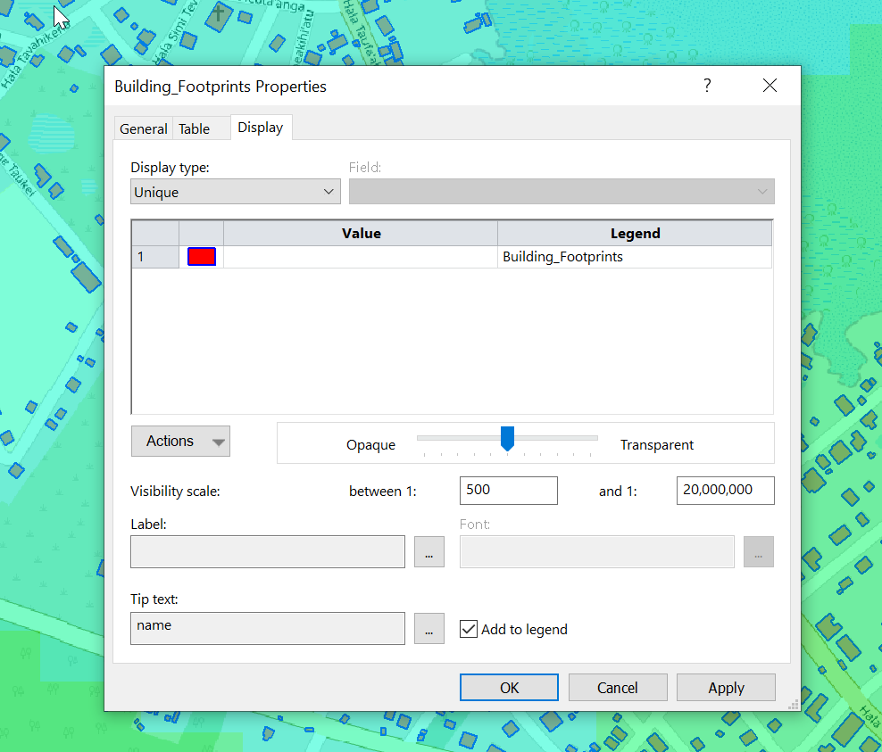
Bingo now we’ve got our building footprints,
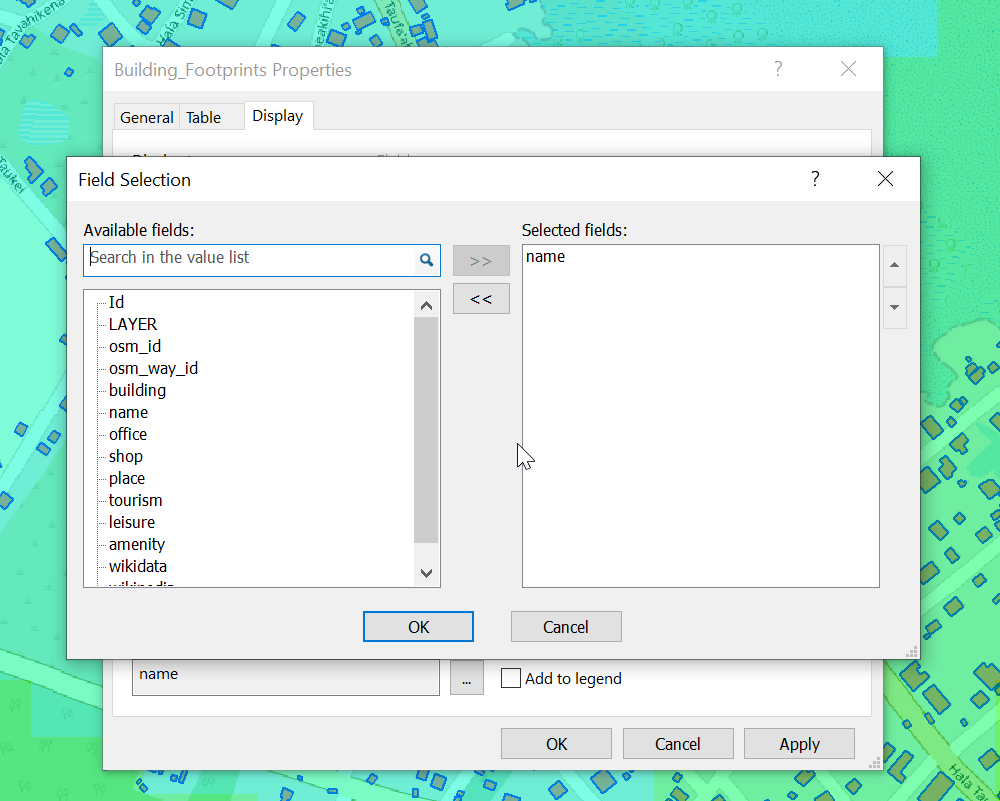
We can change the style of the layer and the labels as needed.
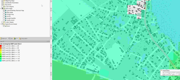
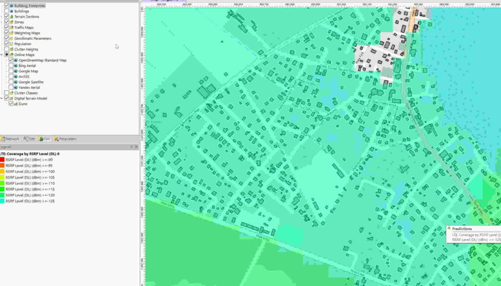
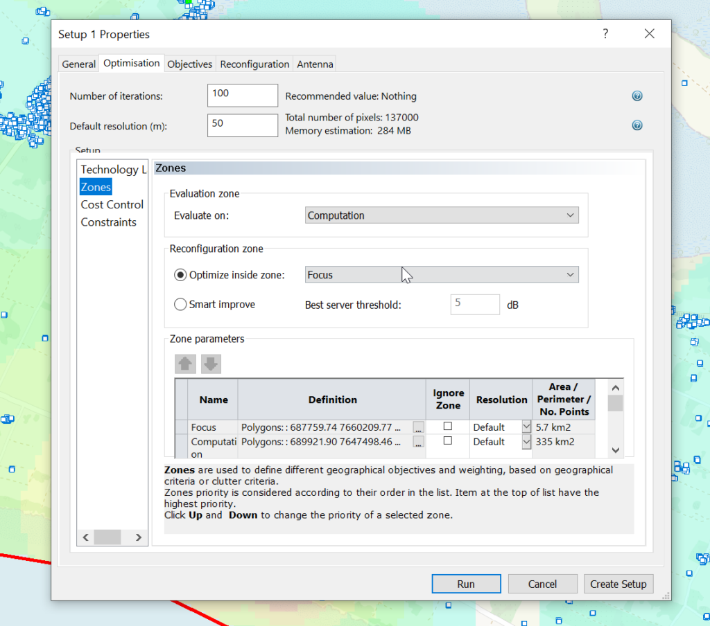
Now we can use the buildings as the Focus Zone / Compute Zone and then run reports and predictions based on those areas.
For example I can run Automatic Cell Planning with the building layers as the Focus zones, to optimize azimuths, tilts and powers to provide coverage to where people live, not just vacant land.
Clutter data describes real world things on the planet’s surface that attenuate signals, for example trees, shrubs, buildings, bodies of water, etc, etc. There’s also different types of trees, some types of trees attenuate signals more than others, different types of buildings are the same.
Getting clutter data used to be crazy expensive, and done on a per country or even per region basis, until the European Space Agency dropped a global dataset free of charge for anyone to use, that covered the entire planet in a single source of data.
So we can use this inside Forsk Atoll for making our predictions.
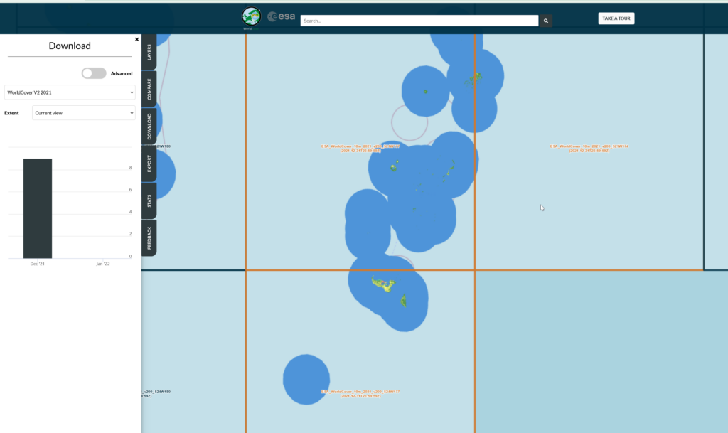
First things first we’ll need to create an account with the ESA (This is not where they take astronaut applications unfortunately, it just gives you access to the datasets).
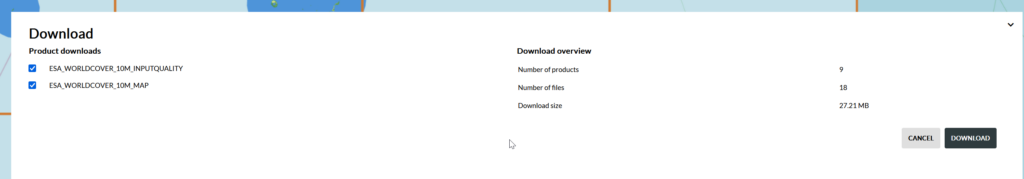
Then you can select the areas (tiles) you want to download after clicking the “Download” tab on the right.
We get a confirmation of the tiles we’re download and we’ll get a ZIP file containing the data.
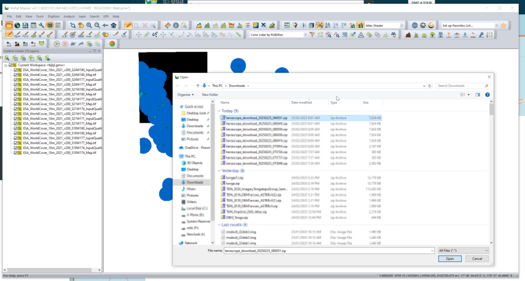
We can load the whole ZIP file (Without needing to extract anything) into GlobalMapper which loads all the layers.
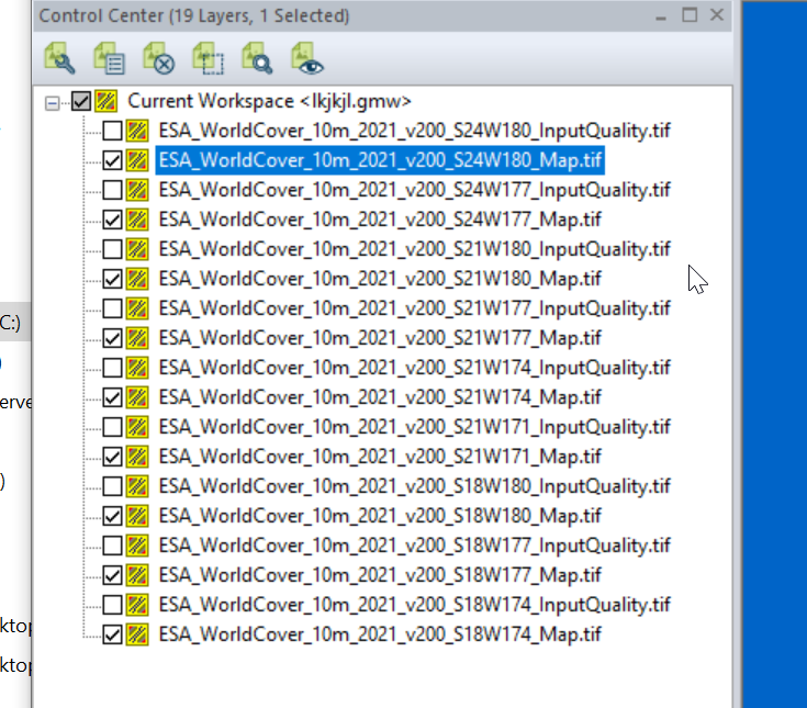
I found the _Map.tif files the highest resolution, so I’m only exporting these.
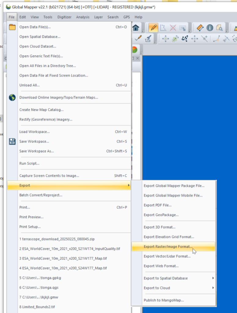
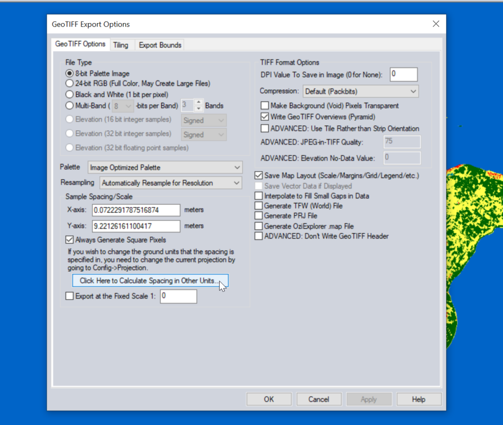
Then we need to export the data to GeoTiff for use in Atoll (The specific GeoTiff format ESA produces them in is not compatible with Atoll hence the need to convert), so we export the layers as Raster / Image format.
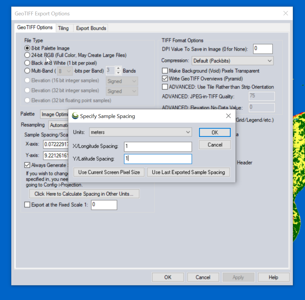
Atoll requires square pixels, and we need them in meters, so we select “Calculate Spacing in Other Units”.
Then set the spacing to meters (I use 1m to match everything else, but the data is actually only 10m accurate, so you could set this to 10m).
You probably want to set the Export Bounds to just the areas you’re interested in, otherwise the data gets really big, really quickly and takes forever to crunch.
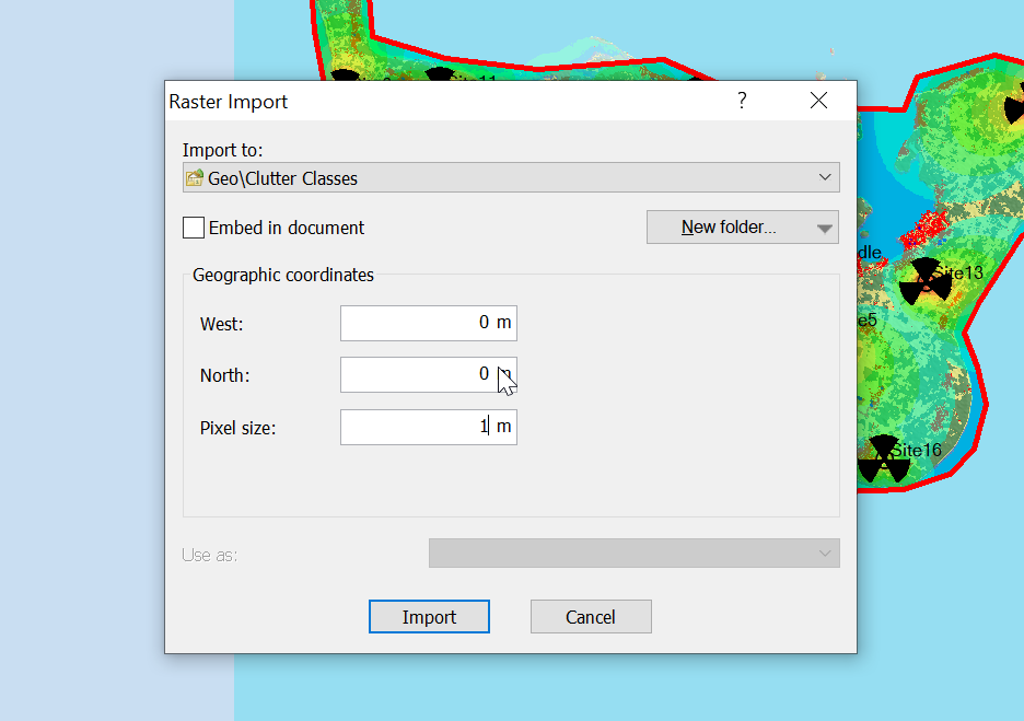
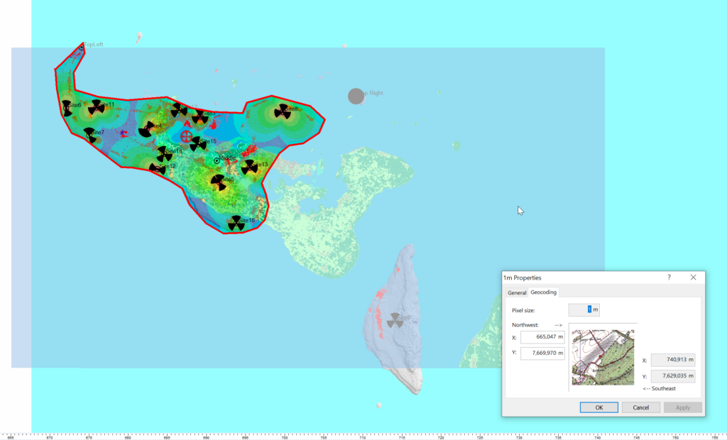
Now for the fancy part, we need to import it into Atoll.
When we import the data we import it as Raster data (Clutter Classes) with a pixel size of 1m.
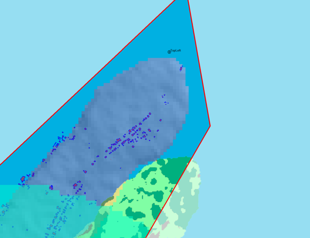
Alas when we exported the data we’ve lost the positioning information, so while we’ve got the clutter data, it’s just there somewhere on the planet, which with the planet being the size it is, is probably not where you need it.
So I cheat, I start put putting the West and North values to match the values from a Cell Site I’ve already got on the map (I put one in the top left and bottom right corners of the map) and use that as the initial value.
Then – and stick with me, this is very technical – I mess with the values until the maps line up into the correct position. Increase X, decrease Y, dialing it it in until the clutter map lines up with the other maps I’ve got.
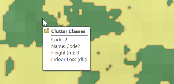
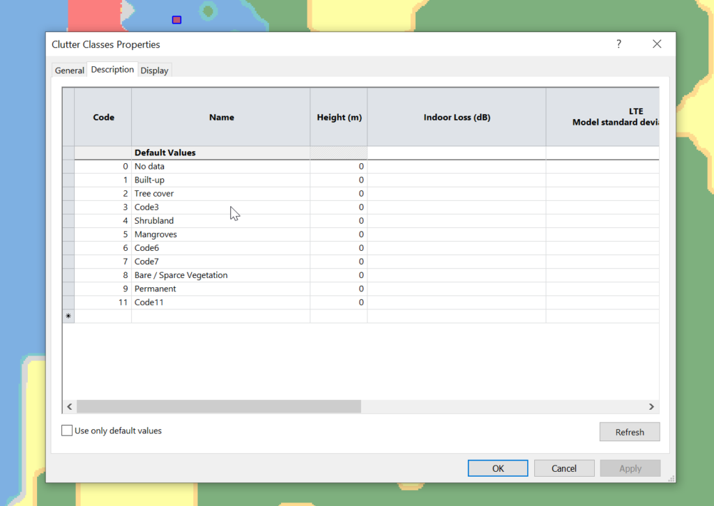
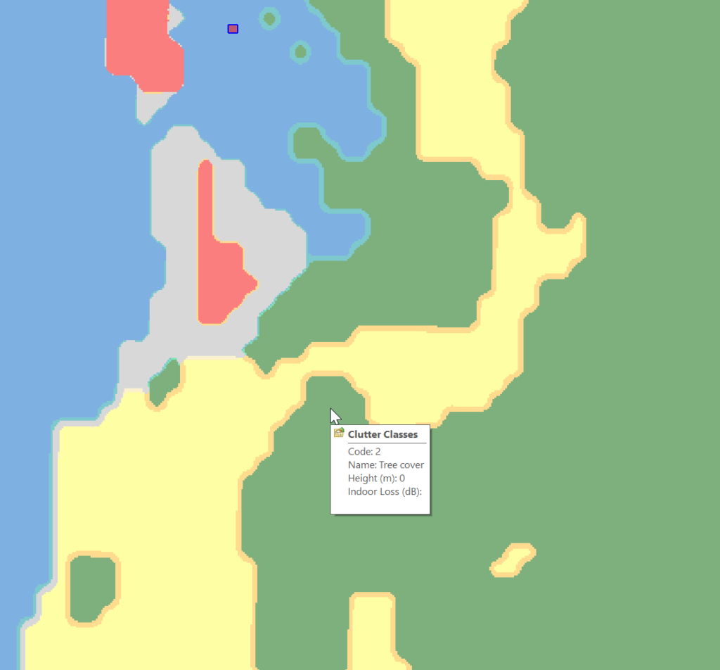
Right, now we’ve got the data but we don’t have any values.
Each color represents a clutter class, but we haven’t set any actual height or losses for that material.
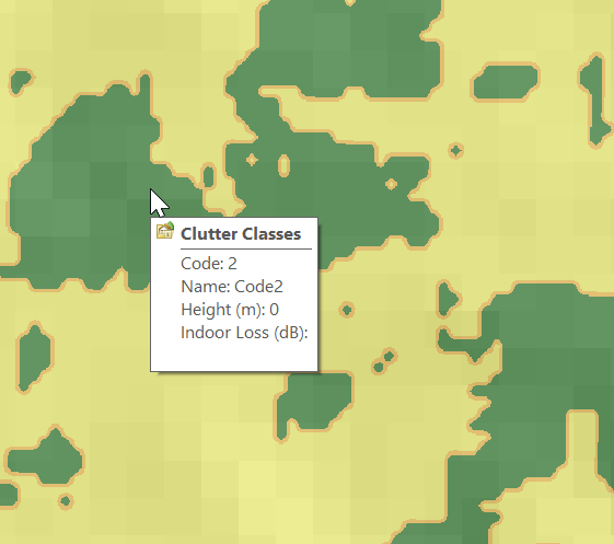
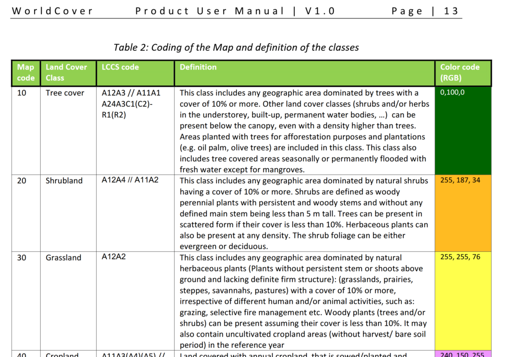
Alas the Map Code does not match with the table in the manual, but the colours do, here’s what mine map to:
Which means when hovering over a layer of clutter I can see the type:
Next we need to populate the heights, indoor and outdoor losses for that given clutter. This is a little more tricky as it’s going to vary geography to geography, but there’s indicative loss numbers available online pretty easily.
Once you’ve got that plugged in you can run your predictions and off you go!
Another post in the “vendors thought Java would last forever but the web would just a fad” series, this one on getting Nokia BTS Site Manager (which is used to administer the pre-Airscale Nokia base stations) running on a modern Linux distro.
For starters we get the installers (you’ll need to get these from Nokia), and install openjdk-8-jre using whichever package manager your distro supports.
Once that’s installed, then extract the installer folder (Like BTS Site Manager FL18_BTSSM_0000_000434_000000-20250323T000206Z-001.zip).
Inside the extracted folder we’ve got a path like:
BTS Site Manager FL18_BTSSM_0000_000434_000000-20250323T000206Z-001/BTS Site Manager FL18_BTSSM_0000_000434_000000/C_Element/SE_UICA/Setup
The Setup folder contains a bunch of binaries.
We make these executable:
chmod +x BTSSiteEM-FL18-0000_000434_000000*
Then run the binary:
sudo ./BTSSiteEM-FL18-0000_000434_000000_x64.bin
By default it installs to /opt/Nokia/Managers/BTS\ Site/BTS\ Site\ Manager
And we’re done. Your OS may or may not have built a link to the app in your “start menu” / launcher.
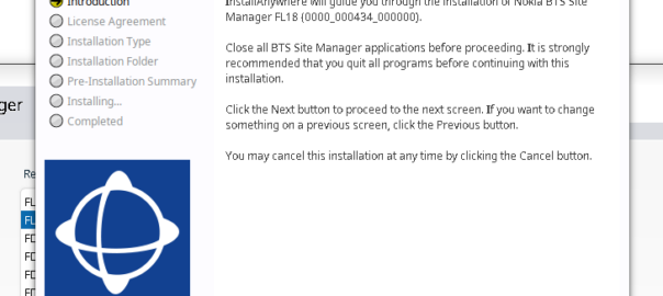
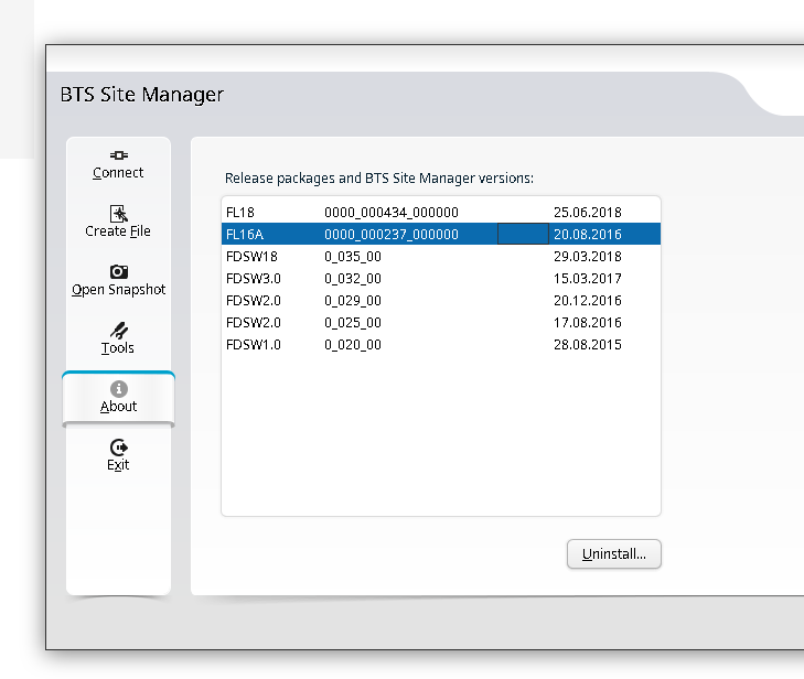
You can use one BTS manager to manage several different versions of software, but you need the definitions for those software loaded.
If you want to load the Releases for other versions (Like other FLF or FL releases) the simplest way is just to install the BTS site manager for those versions and just use the latest, then you’ll get the table of installed versions in the “About” section that you can administer.
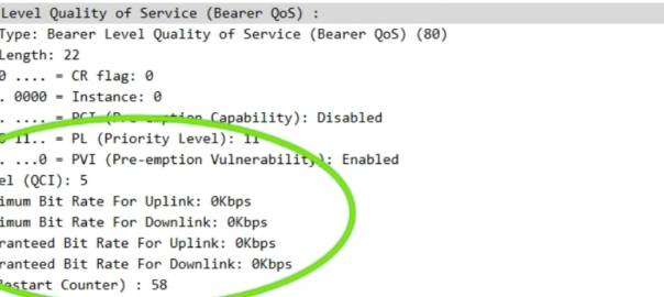
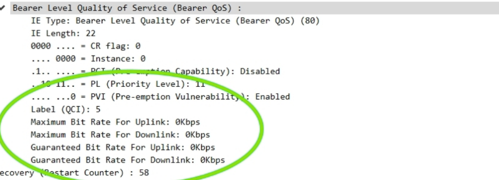
The other day I had a query about a roaming network that was sending Bearer Level QoS parameters in the Create Session Request to 0Kbps, up and down rather than populating the MBR values.
I knew for Guaranteed Bit Rate bearers that this was of course set, but for non GBR bearers (QCI 5 to 9) I figured this would be set the to MBR, but that’s not the case.
So what gives?
Well, according to TS 29.274:
For non-GBR bearers, both the UL/DL MBR and GBR should be set to zero.
So there you have it, if it’s not a QCI 1-4 bearer then these values are always 0.
Concrete, steel and labor are some of the biggest costs in building a cell site, and yet all the focus on cost savings for cell sites seems to focus on the RAN, but the actual RAN equipment isn’t all that much when you put it into context.
I think this is mostly because there aren’t folks at MWC promoting concrete each year.
But while I can’t provide any fancy tricks to make towers stronger or need less concrete for foundations, there’s some potential low-hanging fruit in terms of installation of sites that could save time (and therefor cost) during network refreshes.
I don’t think many folks managing the RAN roll-outs for MNOs have actually spent a week with a tower crew rolling this stuff out. It’s hard work but a lot of it could be done more efficiently if those writing the MOPs and deciding on the processes had more experience in the field.
Disclaimer: I’m primarily a core networks person, this is the job done from a comfy chair. This is just some observations from the bits of work I’ve done in the field building RAN.
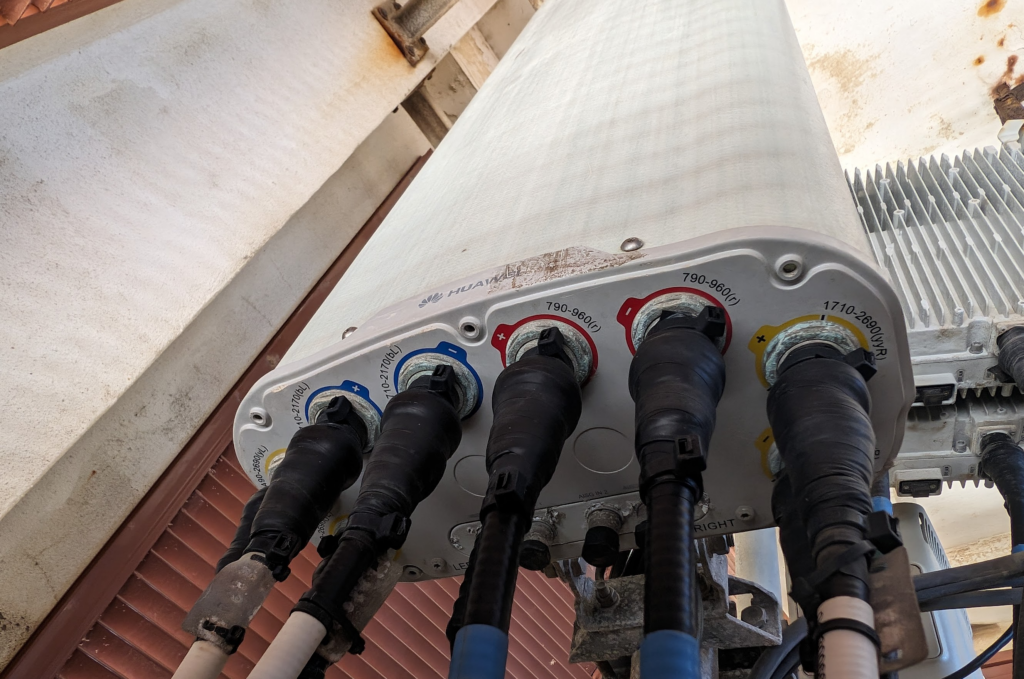
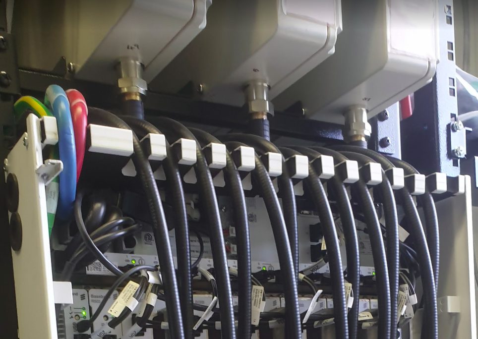
Standardize Power Connectors
Currently radio units from the biggest RAN vendors (Ericsson, Nokia, Huawei, ZTE & Samsung) each use different DC power connectors.
This means if you’re swapping from one of these vendors to another as part of a refresh, you need new power connectors.
If you’re lucky you’re able to reuse the existing DC power cables on the tower, but that means you’re up on a tower trying to re-terminate a cable which is a fiddly job to do on the ground, and far worse in the air. Or if you’re unlucky you don’t have enough spare distance on the DC cables to do the job, then you’re hauling new DC cables up a tower (and using more cables too).
While Huawei and ZTE have adopted for push connectors with the raw cables behind a little waterproof door.
If we could just settle on one approach (either is fine) this could save hours of install time on each cell site, extrapolate that across thousands of cell sites for each network, and this is a potentially large saving.
Standardize Fiber Cables
The same goes for waterproofing fibre, Ericsson has a boot kit that gets assembled inline over the connectors, Nokia has this too, as well as a rubber slide over cover boot on pre-term cables.
Again, the cost is fairly minimal, but the time to swap is not. If we could standardize a break out box format on the top of the tower and a LC waterproofing standard, we could save significant time during installs, and as long as you over-provision the breakout (The cost difference between a 6 core fiber vs a 48 core fibre is a few dollars), you can save significant time having to rerun cables.
Yes, we’ve all got horror stories about someone over-bending fiber, and if you reused fibre between hardware refresh cycles, but modern fiber is crazy tough so the chances of damaging the reused fiber is pretty slim, and spare pairs are always a good thing.
Preterm DC Cables
Every cell site install features some poor person squatting on the floor (if they’re savvy they’ve got a camping stool or gardening kneeling mat) with a “gut buster” crimping tool swaging on connectors for the DC lugs.
If we just used the same lugs / connectors for all the DC kit inside the cell sites, we could have premade DC cables in various lengths (like everyone does with Ethernet cables now), rather than making each and every cable off a spool (even if it is a good ab workout).
I dunno, I’m just some Core network person who looks at how long all this takes and wonders if there’s a way it could be done better, am I crazy?
Nope – it doesn’t do anything useful. So why is it there?
The SUBSCRIBE method in SIP allows a SIP UAC to subscribe to events, and then get NOTIFY messages when that event happens.
In a plain SIP scenario (RFC 3261), we can imagine an IP Phone and a PBX scenario. I might have “Busy Lamp Field” aka BLF buttons on the screen of my phone, that change colour when the people I call often are themselves on calls or on DND, so I know not to transfer calls to them – This is often called the “presence” scenario as it allows us to monitor the presence of another user.
At a SIP level, this is done by sending a SUBSCRIBE to the PBX with the information about what I’m interested in being told about (State changes for specific users) and then the PBX will send NOTIFY messages when the state changes.
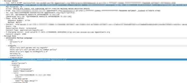
But in IMS you’ll see SUBSCRIBE messages every time the subscriber registers, so what are they subscribing for?
Well, you’re just subscribing to your own registration status, but your phone knows your own registration status, because it’s, well, the registration status of the phone.
So what does it achieve? Nothing.
The idea was in a fixed-mobile-convergence scenario (keeping in mind that’s one of the key goals from the 2008 IMS spec) you could have the BLF / presence functionality for fixed subscribers, but this rareley happens.
For the past few years we’ve just been sending a 200 OK to SUBSCRIBE messages to the IMS, with a super long expiry, just to avoid wasting clock cycles.
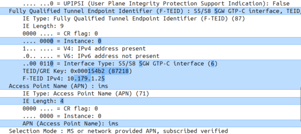
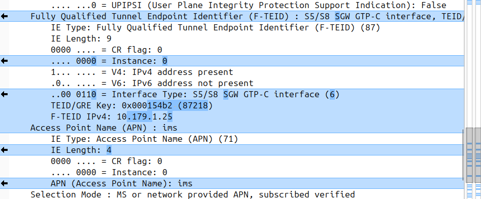
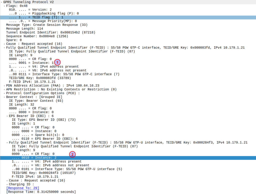
I was diffing two PCAPs the other day trying to work out what’s up, and noticed the Instance ID on a GTPv2 IE was different between the working and failing examples.
If more than one grouped information elements of the same type, but for a different purpose are sent with a message,
these IEs shall have different Instance values.
So if we’ve got two IEs of the same IE type (As we often do; F-TEIDs with IE Type 87 may have multiple instances in the same message each with different F-TEID interface types), then we differentiate between them by Instance ID.
The only exception to this rule is where we’ve got the same data, so if you’ve got one IE with the exact same values and purpose that exists twice inside the message.
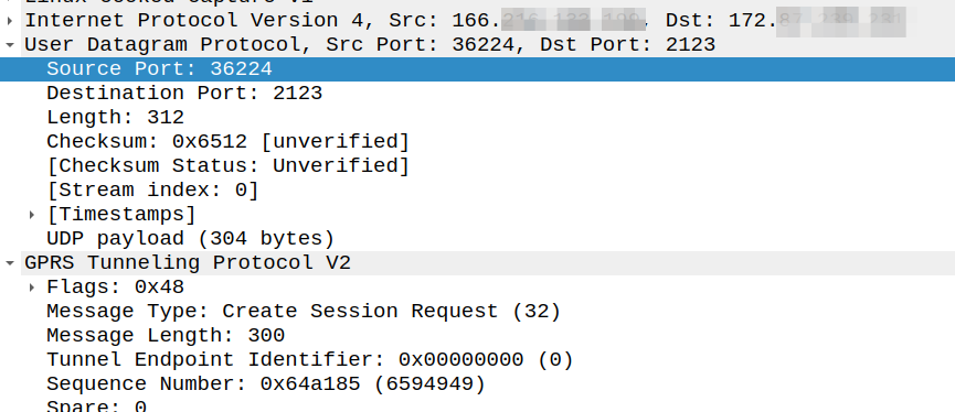
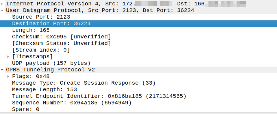
Ask anyone in the industry and they’ll tell you that GTPv2-C (aka GTP-C) uses port 2123, and they’re right, kinda.
Per TS 129.274 the Create Session Request should be sent to port 2123, but the source port can be any port:
The UDP Source Port for a GTPv2 Initial message is a locally allocated port number at the sending GTP entity.
So this means that while the Destination Port is 2123, the source port is not always 2123.
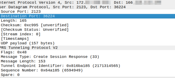
So what about a response to this? Our Create Session Response must go where?
Create Session request coming from 166.x.y.z from a random port 36225 Going to the PGW on 172.x.y.z port 2123
The response goes to the same port the request came on, so for the example above, as the source port was 36225, the Create Session Response must be sent to port 36225.
Because:
The UDP Destination Port value of a GTPv2 Triggered message and for a Triggered Reply message shall be the value of the UDP Source Port of the corresponding message to which this GTPv2 entity is replying, except in the case of the SGSN pool scenario.
But that’s where the association ends.
So if our PGW wants to send a Create Bearer Request to the SGW, that’s an initial message, so must go to port 2123, even if the Create Session Request came from a random different port.