Sometimes I wonder how much crack kit vendors and operator’s marketing teams smoke, and if they ever talk to end users.
I was reading about 5G eRedcap the other day – how it is the next generation of 5G Redcap (reduced capacity – a subset of the UE standard with a cut down feature set to make them cheaper to produce / more power efficient), which is in itself a subset of 5G SA for IoT devices. One of the key pillars 5G SA promised is MmTC (Massive Machine Type Communication) which just means IoT but that’s separate to Redcap and eRedcap. Did I mention none are compatible with each other and some are mutually exclusive. All this is is great because in 4G we had wideband LTE (standard LTE) but also NB-IoT (Aka Narrowband) and also Cat-M1.
So clear and easy to understand.
If you’re designing an IoT enabled rat trap, water meter or widget production line, before you pick the modem to go in your device, you need to know about what IoT technologies are available on what bands from what operators in countries you haven’t even considered selling into yet.
This has been in the front of my mind of late; I’ve been messing around with LTE NB-IoT, so I thought I’d find a dev board that supports NB-IoT (a standard that’s now almost 10 years old) so I can validate it all works.
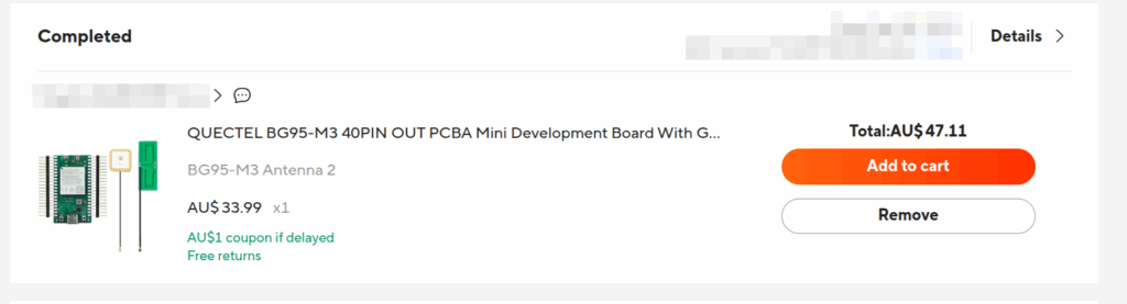
The cheapest NB-IoT capable dev board I could find used a Quectel chipset, BG95-M3, and it cost me $47 AUD (~$30 USD).
By contrast, I can buy a GSM modem on a breakout board in single quantities for $3.50 USD.
There’s a tension here – the cellular industry desperately tries to sunset old tech (because it’s expensive for them to operate), and those building IoT devices are incentiviced to use the cheapest modems for their application – so use the 2G modems because they’re 1/6th the price because it’s cheaper for them to build.
Years ago a family member had purchased a bunch of 2G trailcams, which stopped working when Australia shut off the 2G network. The result is the consumer’s previously working hardware has now stopped working. The vendor washes their hands of it – they can’t control what the operators do, and the operators say they can’t stand in the way of progress, and the consumer just ends up with eWaste and a bad taste in their mouth.
So why is a 2G modem so dammed cheap? Mostly it’s just economies of scale. There’s a handful of GSM bands, and one technology – GSM.
If you’re Qualcomm, SIMcomm, Quectel or any of the other chip vendors, you want to build one chip and sell it to the largest possible market, a good example was the $10 USD USB modems that run Android I wrote about last year.
But for IoT, these more obscure cellular standards are fragmented, with different bands and technologies across multiple operators even in the same country, and that doesn’t scale well to have multiple different SKUs for slight variations in the same product.
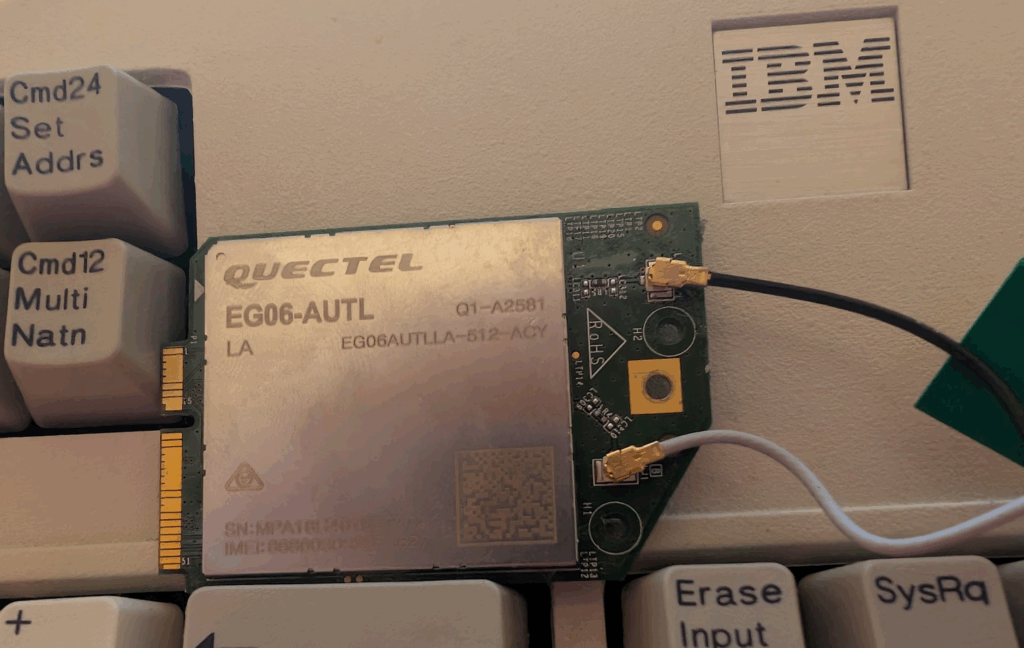
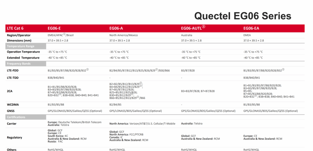
Here’s a random Quectel chip on my desk I pulled out of a modem, it’s the EG06-AUTL, which if we look at the datasheet is the Australian variant, only for Telstra, but the EG06-E would work for Australia too, but not the EG06-EA or EG06-A (Yes, this isn’t strictly an IoT chip but you get the point).
WiFi chips like the ubiquitous ESP8266 are under $2 USD, have no ongoing monthly and work anywhere in the world. If I need more range a LoRa module costs ~$5 USD and has no reliance on local cellular networks, and again, no ongoing subscription. And with WiFi and LoRa, no one can unilaterally say “We’re turning off this network”.
A few years ago I did some work on an island where we replaced dial up modem banks belonging to the local water corporation with LTE Routers connected to an LTE network we’d helped build.
The water monitoring kit talked Modbus from the 1970s and didn’t give a stuff about if it was going on LTE or point to point dial up links – it was like the wise old turtle who’d seen standards come and go.
If you’ve read this far maybe you’re expecting some call to action or deep insight, maybe you’ve been reading this blog long enough to know not to expect such things from me. The more I think about it the more I wonder if the cellular industry should just give up on IoT. The ARPUs for IoT are minuscule, the cost to deliver is high and there are a multitude of competing technologies out there.
I’m not suggesting exiting the space entirely, but when it’s cheaper to buy a full fat LTE modem then an LTE NB-IoT modem, the use case for having a dedicated subset of a standard like NB-IoT or Redcap could be scrapped – If device manufacturers want cellular, they include full cellular, and if they want low power, long battery life, etc, they go Lora or WiFi or any of the other competing standards they were going to pick anyway.
PFCP includes a “Redirect Information” IE, which if set, allows you to change the forwarding action in PFCP to Redirect traffic.
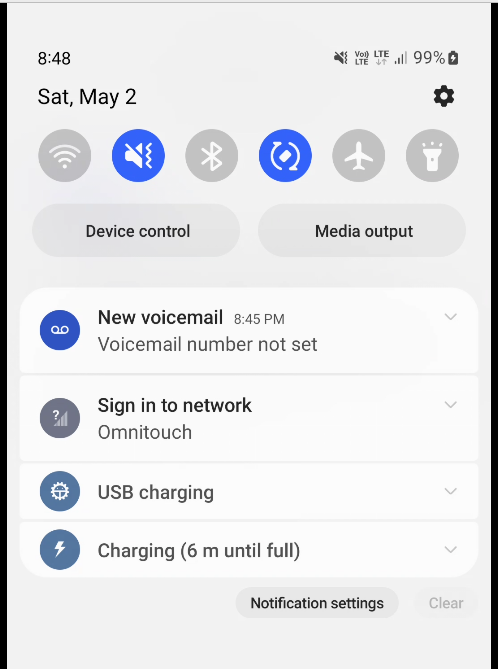
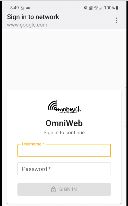
We use this for walled garden redirects, when the OCS reports credit exhausted to the PGW-C, the PGW-C can tell the UPF (PGW-U) that all the traffic from a given subscriber should be redirected to a captive portal / walled garden, like a “Topup Now Page” you’d be used to seeing on Airport WiFi.
“Sign in to network” prompt presented on Cellular
Here’s what the spec says:
8.37. Redirect-Server AVP The Redirect-Server AVP (AVP Code 434) is of type Grouped and contains the address information of the redirect server (e.g., HTTP redirect server, SIP Server) with which the end user is to be connected when the account cannot cover the service cost. It MUST be present when the Final-Unit-Action AVP is set to REDIRECT. It is defined as follows (per the grouped-avp-def of RFC 3588 [DIAMBASE]): Redirect-Server ::= < AVP Header: 434 > { Redirect-Address-Type } { Redirect-Server-Address }
So how does this work in practice?
Once upon a time, you’d just intercept all HTTP request and serve your own content, but it’s not 2005 on Starbucks WiFi anymore, and SSL is everywhere.
Luckily this is a (mostly) solved problem, Apple has “Captive Network Assistant” that probes http://captive.apple.com/hotspot-detect.html and checks for a specific response, Google’s Android has http://connectivitycheck.gstatic.com/generate_204 and does the same thing.
But before I can tell you what we do, I’ll show you what we’re not doing before we do the doing so you can see what the do does by looking at what happens when we don’t – Clear?
Before we send any Session Modification Request with redirect I can do a DNS lookup, here’s an example from our test jig that goes to Facebook:
A Record lookup for facebook.com resolving to 57.145.8.1
This is just a regular A record DNS query wrapped up in GTP-U as it’d look from a eNB/gNB/SGW that gets an answer back also in GTP-U.
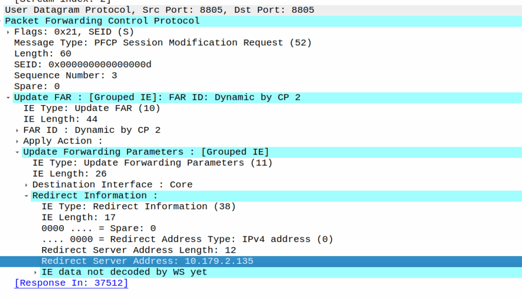
As we’ve already got a session up in our case, the SMF or PGW-C we sends the PFCP Session Modification Request I shared in the screenshot earlier to the UPF.
The Redirect Server Address in the Redirect Information IE in PFCP
We do a few things on the UPF at this point, the first, is that we block forwarding access to all IPs except 10.179.2.135 (The redirect server in the screenshot), and we steal / intercept all DNS queries.
This means if you query facebook.com after the Redirect Information is in place, you get back an A-Record answer for facebook.com but it’s telling you Facebook lives on our redirect server.
We’ve got a whitelist on our UPF for certain domains, so if we’re sending you to a self-signup page, you’re going to need to be able to hit our payment processors portals (Stripe, Paypal, etc), so we need to allow their domains, but we don’t know their IPs, so instead we do server side DNS lookups (via our DNS servers before you sneaky kids get any other ideas) for the whitelsited domains, and if it’s on our DNS whitelist, we allow resolution to those domains and allow access to those IPs returned in the DNS response.
In my lab I’m redirecting HTTP traffic to a management server
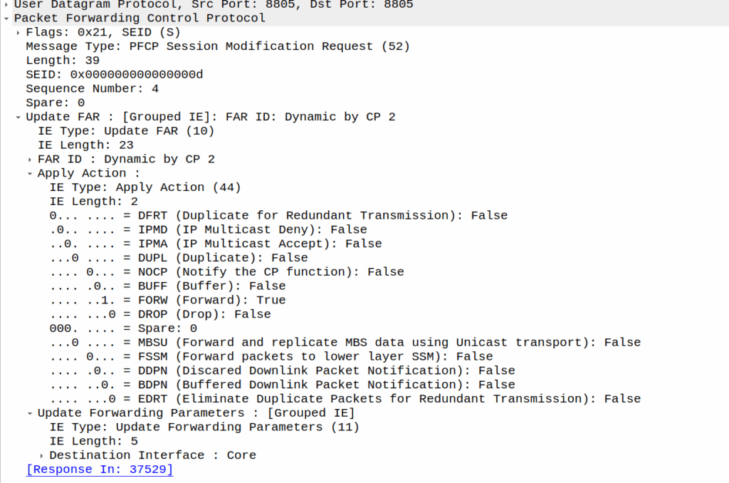
Turning it off just involves sending another PFCP Session Modification Request but without the redirect information.
We support a network in Alaska, and one of the guys we work with there – John – has a story (which I’ll steal here) where he gets a phone call late at night from someone saying they’re in the US Air Force, and uh, they’ve, uh, lost a plane. And since John works for the phone company, he wouldn’t have any idea where it is would you? They ask him.
As a matter of fact, John could see the last cell the SIM the pilot was carrying was attached to, they sent a helicopter out and found the pilot, who survived.
This was a long time ago, and he was able to pin the location down to a cell (sector), and lookup which direction the sectors were pointing for that cell and the location of it, to give a pretty good idea of the general search area.
Now that everyone carries a GPS in their pockets, the level of accuracy here is a lot more than just which cell are you served by (although that’s a lot of accuracy anyway, and not to be ignored).
There’s significant privacy implications here and a lot of misinformation about pinging cell towers and “zoom enhance” stuff.
I figured I’d actually share how this works IRL – There’s nothing ‘secret‘ here – All of this stuff is in the 3GPP standards which outline how mobile networks should behave.
There’s roughly 4 levels of accuracy in cell phone networks, we’ll cover each one, and how the network treats it.
(I’m talking 4G/5G here as most of the world has moved on or is already moving on from 2G/3G)
Tracking Area Level Accuracy
Cell sites get grouped into tracking areas, they’re kinda like broadcast domains in TCP/IP networking, when you need to “page” (find) a phone that’s “idle” (sleeping) you page the tracking area.
Tracking Area sizing has sweet spots, you want more than a few cells, commonly about a dozen or so in the same geographic area get lumped into the same tracking area. In regional areas you might have a large geographic area – Up to a few hundred Km in regional Australia for example, lumped into a single tracking area, whereas in a city that might be a single city block.
If you move between cells inside the same tracking area, then your phone doesn’t need to say to the network “hey I’m moving cells” – It’s only if we go over to a new tracking area that the phone needs to wake up and tell the network it’s now in this new tracking area.
(If you’ve got a tracking area that’s too big (too many cells) then it becomes a nightmare to find who you’re looking for, as the paging channels are always blaring out IDs, tracking areas too small and you’ve got phones having to constantly say “hey I’m moving to this tracking area now” – If you want to learn more about Tracking Areas I’ve written about them on the blog before)
The core network (MME/AMF) always knows the location of a phone at minimum to the tracking area – It’s the base level of location the network has to work with.
Cell ID Level Accuracy (CGI / E-CGI)
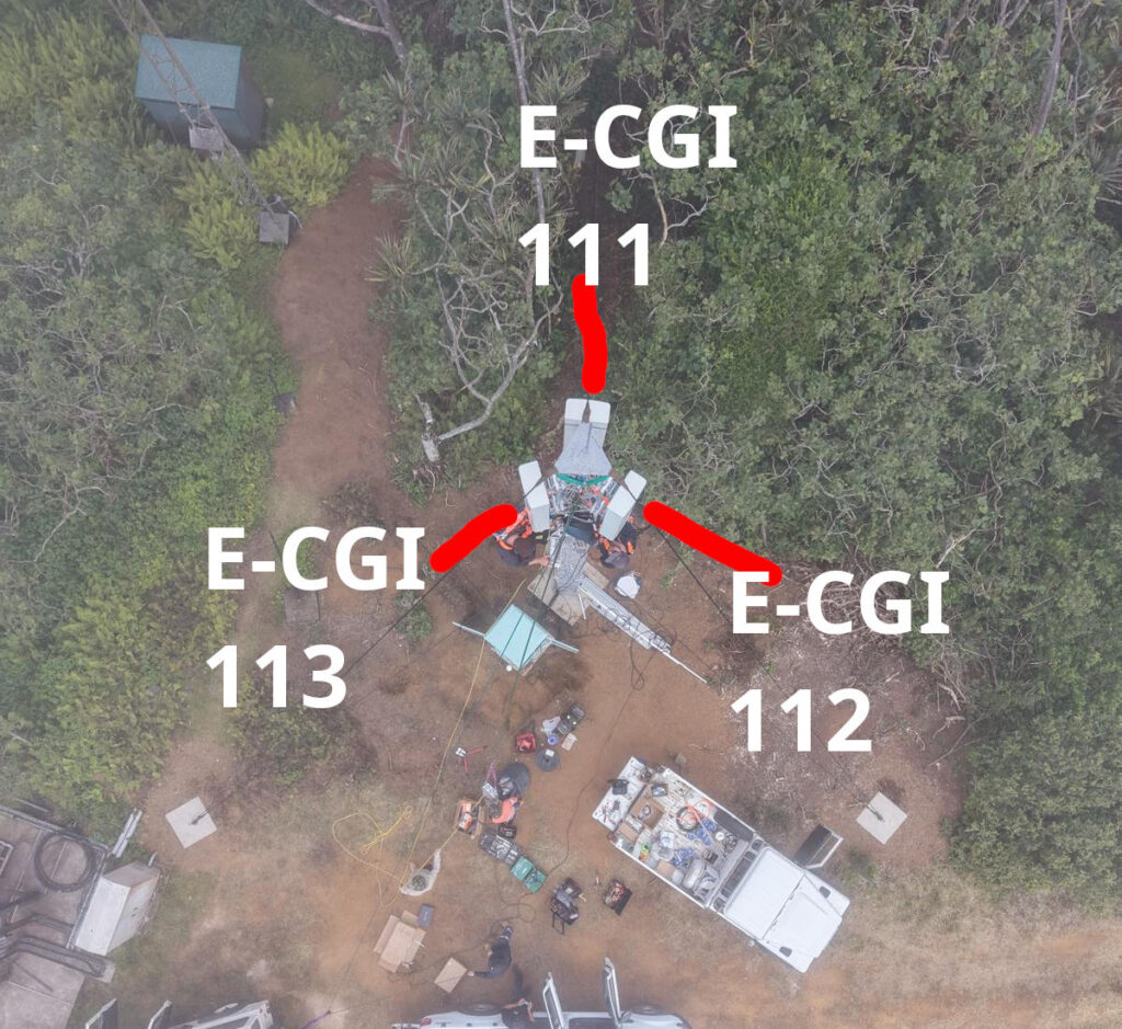
Every cell site sector (cell) has a unique ID to denote which carrier you’re connected to. If you’ve got a 3 sector site, with a single layer per cell sector, then that’s 3 Cell Global Identifiers (CGIs) – one for each sector.
Here’s a tower we put up recently, the CGIs I’ve drawn on are just examples, but if you’re connected to the sector facing North, you’d have CGI of 111, if you’re connected to the cell to the south east, you’d have 112, and the one to the south west would be 113.
CGIs are just numbers, they could be any number, all that matters is that number is unique (ish) in the network, they don’t need to be sequential, or have any common digits.
If we know the CGI of a given user we can kinda draw a 1/3rd wedge off the side of the tower in the direction the antenna is pointing, and if you’re inside that wedge, and that tower is still providing coverage, then we know the customer is somewhere inside that wedge.
But those wedges can still be large, so the margin of error for locating someone is still pretty large. You can probably answer the question of “Are they in the office or are they at home” if they’re in different suburbs.
When the network wants to know a bit more about where the phone is located, it can ask the cell site which Global Cell ID the phone is in, this is pretty rare, but can be done. When the phone is actively doing stuff, like making a call, using data or sending a text, the network knows the CGI of the event.
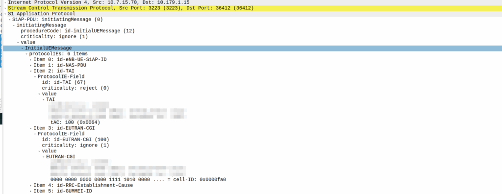
My lab is setup with CGI 4000 and TAC 100, and this information is littered across every signaling message.
Initial Attach message
Note: The encoding shows up as 0000 0000 0000 0000 1111 1010 0000 …. = cell-ID: 0x0000fa0 for CGI 4000, just roll with it, the spec explains why this is.
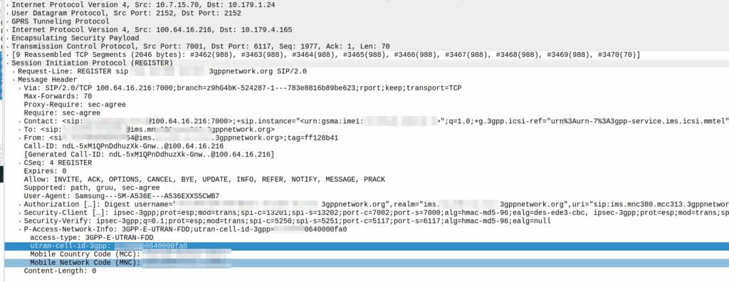
A SIP REGISTER message from my lab, showing the CGI (00640000fa0)
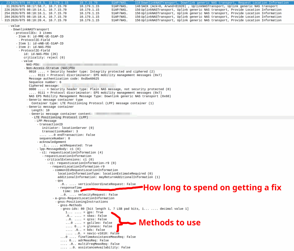
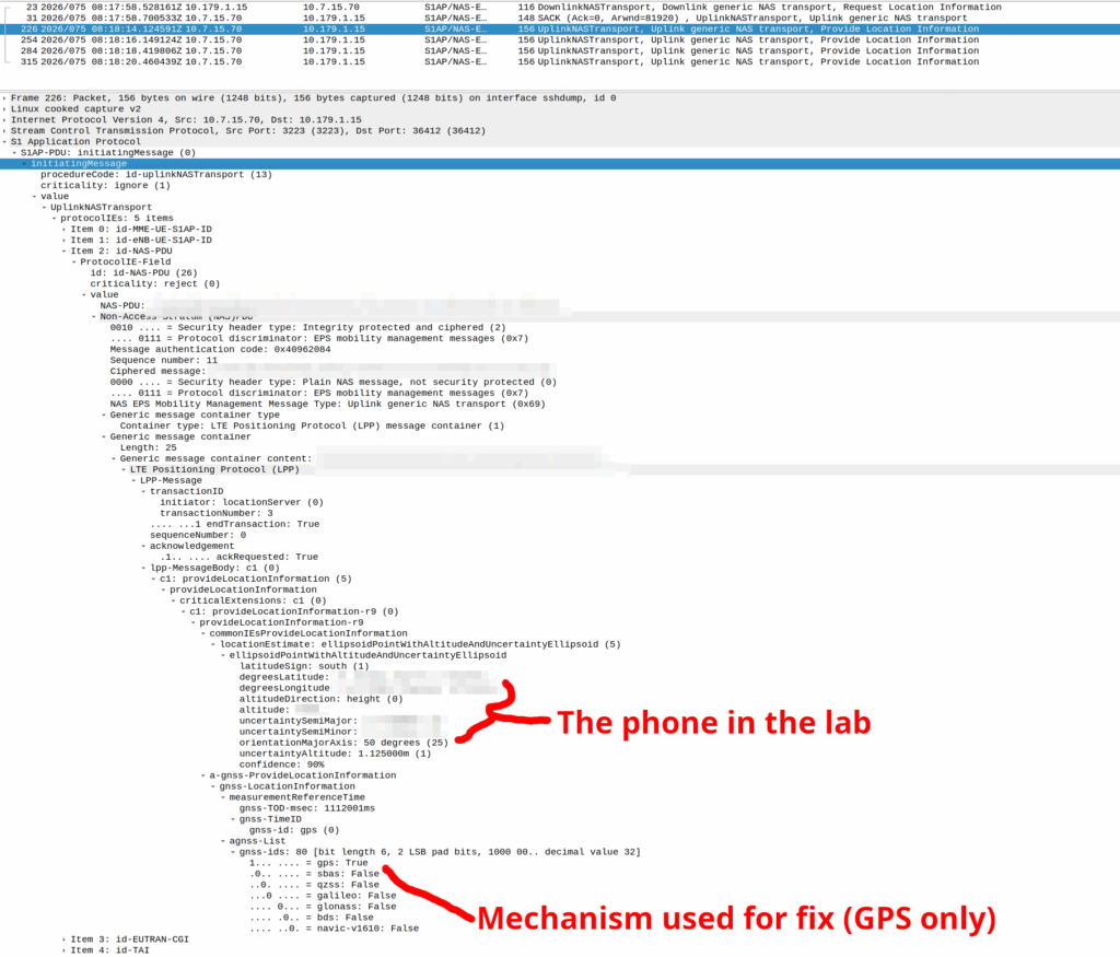
GNSS LPP Positioning
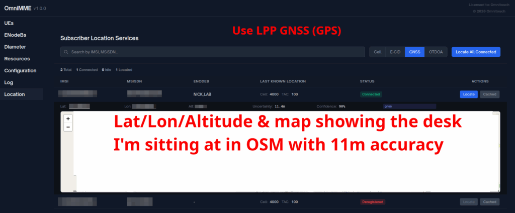
When the Cell ID level is not accurate enough, the network can request the phone to provide it’s location, using whatever it’s got available to it.
In reality, this is either done by an engineer from the phone company with the permissions to do so, or directly by law enforcement using the SLh/SLg Diameter interfaces.
When an engineer does it, there’s usually a portal they can go to, like this one in OmniMME, they search the IMSI or MSISDN, and then can get the location information via a variety of methods.
Your phone gets a message from the network, that says “Hey phone, tell me where you are”.
If you’ve got enough access to the baseband you can even block these requests should you feel so inclined.
I’ve included some Wireshark captures of how this actually looks and how it looks from the Web UI of the MME, with the address removed.
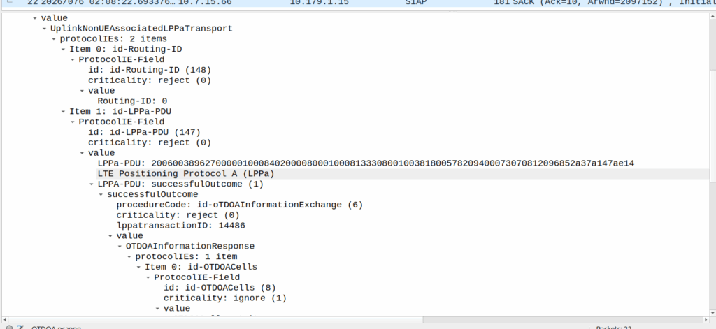
OTDOA – “Pinging”
Sometimes you don’t get an indoor location with GPS or the phone might be too old to support LPP Positioning, no GPS built in or something.
In those scenarios, we use “Time Difference of Arrival” to calculate the position by measuring time between 2 or more cell sites, and calculating the time between when a signal was sent to a phone, and when it receives it, to calculate distance from the base station.
This is better than CGI as it gives you an idea of how far from the cell site the phone is, and the cell site, but it doesn’t return a map with “you are here”, but rather some rough distances, and CGIs for each cell it can see.
The engineer then pulls up a map of all the cell sites, finds the CGIs the cell phone can see, headings for each CGI and tries to do some early high school maths like someones life actually depends on it.
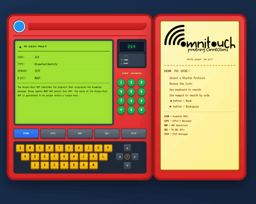
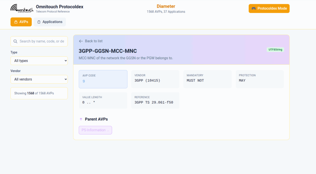
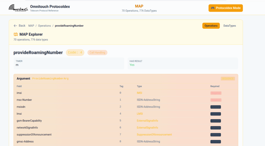
I do a lot of protocol testing, writing Diameter/PFCP/GTP-C etc, and spend a lot of time referencing the standards.
So I built this – Inspired by a 1990s video game / TV / Playing card franchise online reference tool, but rather than identifying pocket monsters, it’s identifying AVPs and stuff
You can punch in the AVP code, AVP name, description, etc, for Diameter, PFCP, GTP-C, MAP or SBI and see all the details to go with it.
I’ve been using it a heap, hopefully some of you might find it useful:
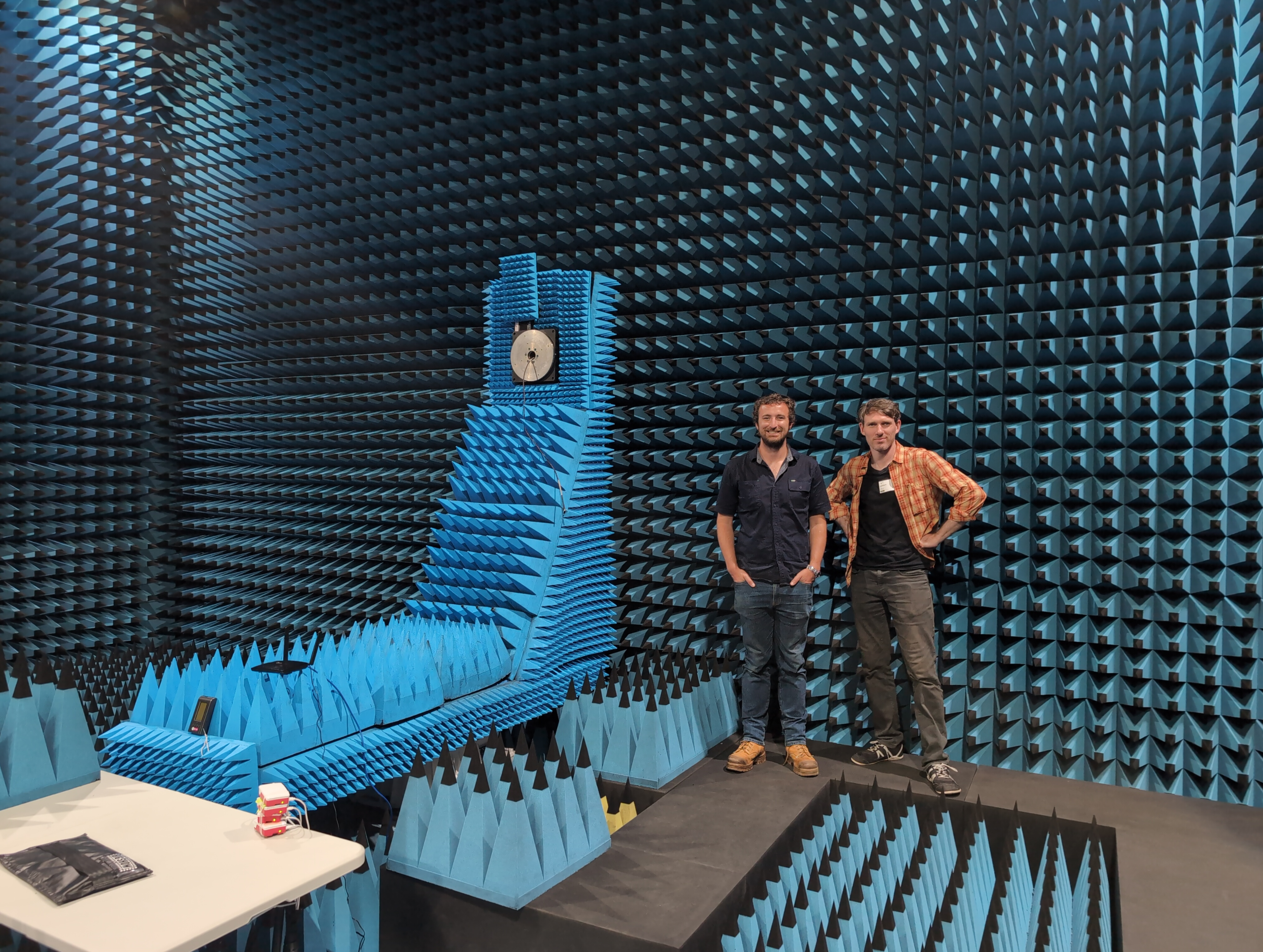
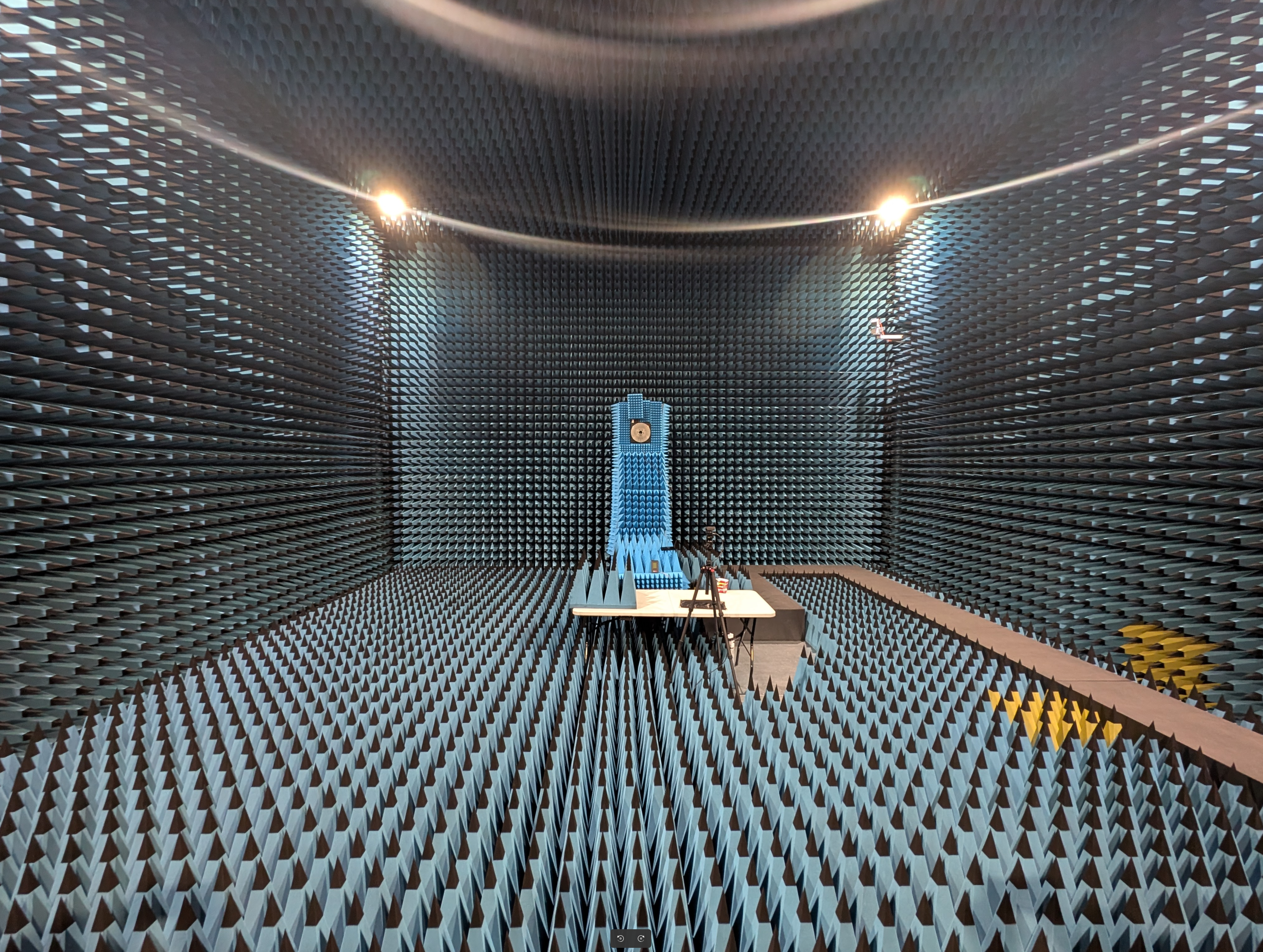
I was recently in Sydney for a GSMA event with a few extra days in town to show one of our team members who was visiting from the US, around a city I don’t even live in.
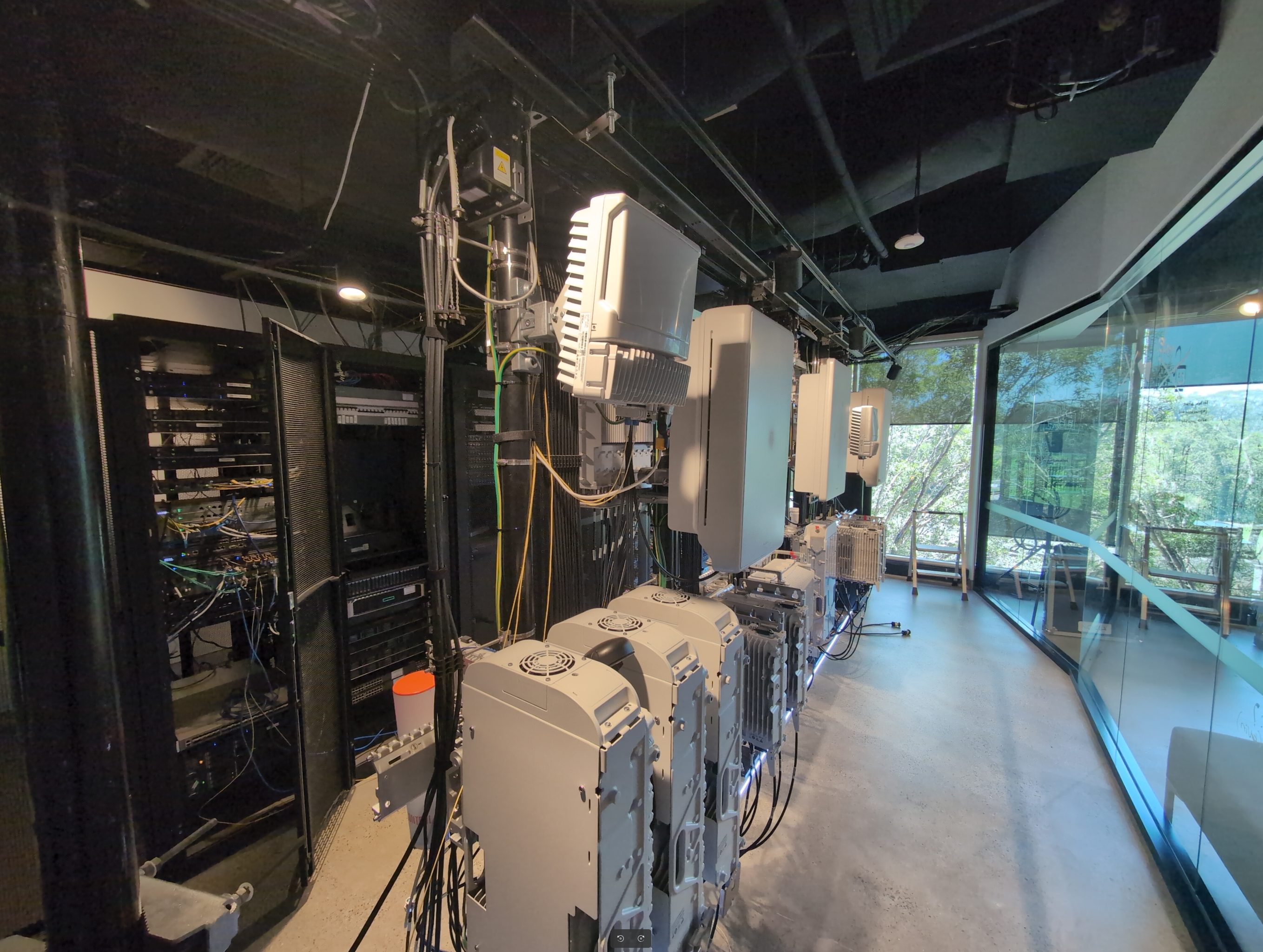
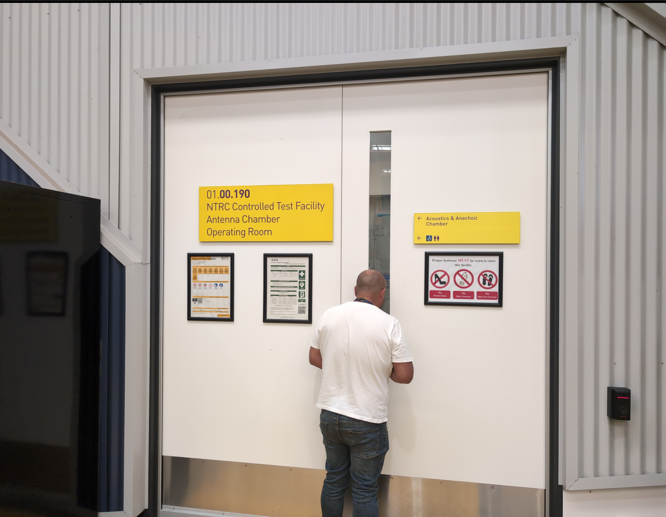
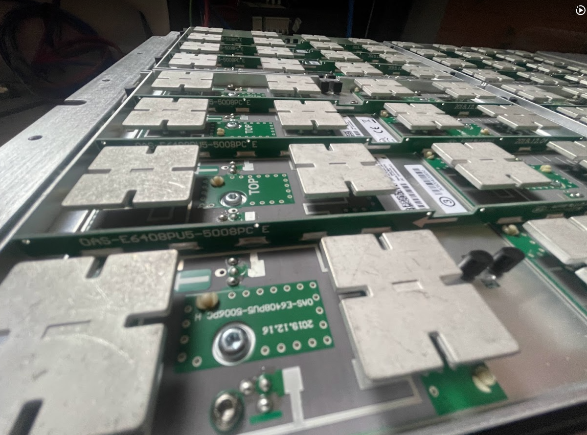
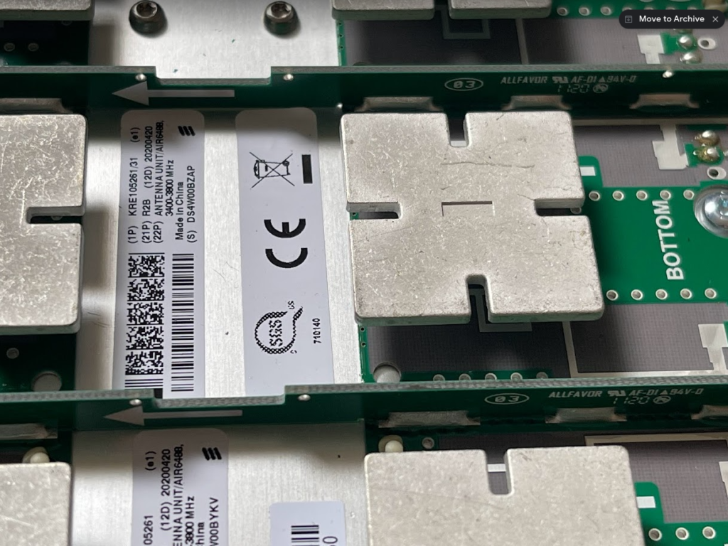
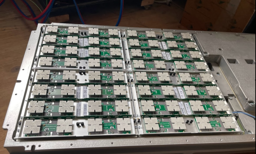
So I reached out to our Nokia account manager and asked if I could visit “The pointy room” – The antenna chamber they’ve got there and Nokia lab.
It did not disappoint.
As well as all the fancy RAN kit and pointy room, they’ve got the kind of machine shop I dream of.
Thanks to Paul, Dave and Ed for showing me around.
We also had a few days hiking in the Blue Mountains, not as impressive as RAN kit.
The Network Repository Function is essentially a database used to store/query information about NFs on the network.
To do this, the NRF has 3 services: the Nnrf_NFManagement Service is used to insert/update/remove records into the database of NFs on the network, the Nrf_NFDiscovery service is used to query this database, and the OAuth2 Authorization service is used to authenticate / authorize the transactions of the first two securely.
The Nnrf_NFManagement Service
The Nnrf_NFManagement Service is the service that handles the registration, deregistration and updating the database of service-producing NFs.
When a NF offering a service becomes ready for service, it registers with the NRF to advise the NRF of the services it offers and so service-consumers (Clients) are able to find and then request services from this NF.
Let’s take a look at the NFRegister process, which is the service operation used to register an NF in the NRF.
At its heart, the NFRegister process is a HTTP2 PUT sent from the NF to the NRF to the path <nrf_ip>/nnrf-nfm/v1/nf-instances/{nrf-instance-id} with a JSON payload containing all the specifics of the services being offered by the NF (NFProfile), which is sent to the NRF.
The NRF parses through the message body (That JSON Payload containing the NFProfile) and adds all this info to the internal database in the NRF as to which service producers it has available.
If this is all OK from the NRF’s perspective, then a 200 OK is sent back by the NRF.
The NFProfile JSON body
The NFProfile is a JSON encoded message body that contains all the info about the NF that the NRF takes and adds to its internal database of services offered by that NF.
nfInstanceID – The Network Function Instance ID is the unique identity if this NF. (It’s also included in the Request URI) It’s a unique ID and typically generated randomly by the NF itself.
nfType – The type of the NF itself, there’s a long list of supported NF Types, NRF, UDM, AMF, SMF, AUSF, etc, etc.
nfStatus – Is the status of the NF, either REGISTERED (Discoverable by other NFs), SUSPENDED (Registered in the NRF but not able to be discovered / invisible, NFs in this state are usually here because they’ve had a high failure rate or haven’t been responding to heartbeats), UNDISCOVERABLE (Used when an NF wants to stop offering services to new consumers, but is still able to offer services to existing consumers, the idea being this is taking it out of the discovery pool, but still able to serve in-process requests).
plmnList – This is a list of PLMNs that this NF serves.
fqdn – The Fully Qualified Domain name of the NF
IPv4Address / IPv6Address – The IPv4 and/or IPv6 address of the NF
nfService – This is a list of JSON objects, detailing the services offered by the NF, such as the service names it is offering, version of the service, IDs of the service instances and IP Endpoints for requests to be sent to.
priority / capacity / load – Used for selection of this NF from the pool and the order of results returned
The Nnrf_NFManagement Service also includes a Subscription service, to allow NFs to subscribe to changes in state, for example getting a notification if a NF that was registered becomes deregistered.
The UE Authentication Service is consumed by the AMF. The AMF initiates the authentication operation, when indicated, as part of the UE registration process. The AUSF performs either 5G-AKA or EAP-based authentication based on information received from the AMF. If EAP authentication is used then the AUSF and the UE exchange EAP messages through the AMF.
3GPP TS 29.509 V16.3.0; 5G System; Authentication Server Services
Common Dialogs on Nausf-auth Service
Authenticate UE – Request
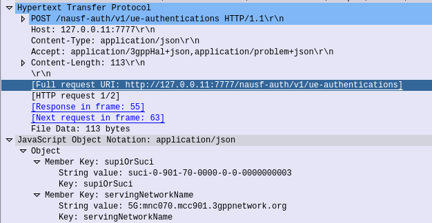
HTTP POST sent from the AMF to the AUSF, to the URL /nausf-auth/v1/ue-authentications with JSON body containing the SUPI or the SUCI, and the serving network name.
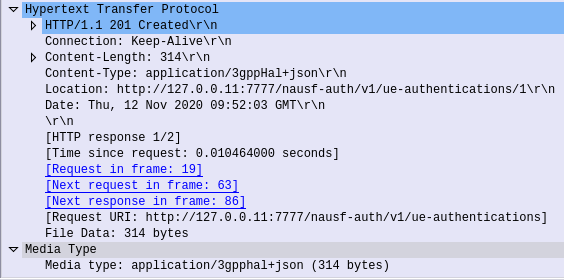
Authenticate UE – Response
If request from the AMF is successfully processed by the AUSF, it sends back a “201 Created” response, with a JSON Body containing the authentication vectors:
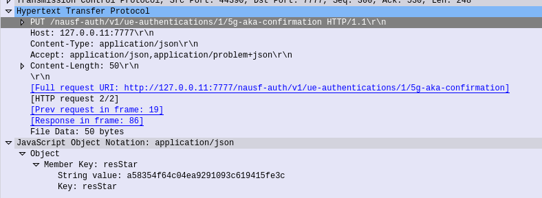
The AMF needs to advise the AUSF the RES returned from the Subscriber (if one was returned) to confirm the UE successfully authenticated, so the AMF sends this in the form of an HTTP PUT to the AUSF to the URL /nausf-auth/v1/ue-authentications/1/5g-aka-confirmation
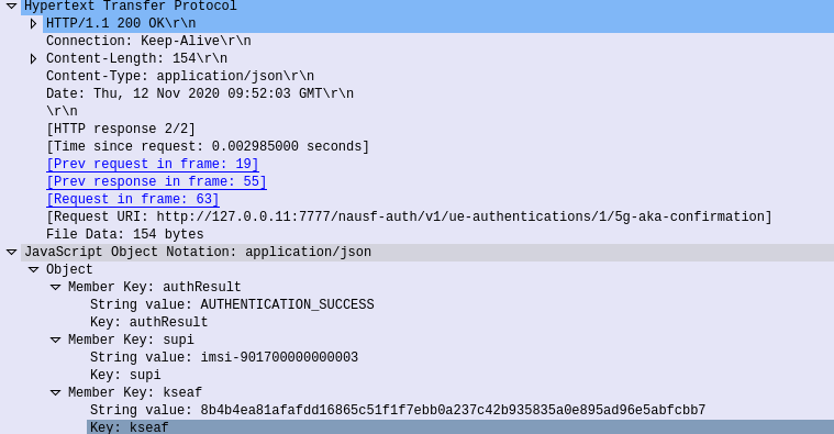
5G-AKA Confirmation – Response
If successful a 200 OK is sent back to the AMF by the AUSF with a JSON body containing the SUPI of the Subscriber (keep in mind the subscriber may have authenticated with a SUCI, so up until this point the AMF doesn’t know the SUPI of the Subscriber), and the Kseaf key used for ciphering and integrity protection.
Common Dialogs on Nudm-ueau Service
The Nudm_UEAuthentication service is used by NF service consumers to obtain UE authentication vectors from the UDM, to inform the UDM of authentication results, to query authentication results, and to purge authentication results.
3GPP TS 29.503 Unified Data Management Services
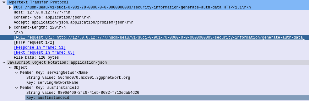
Generate Authentication Data – Request
When the AUSF needs to authenticate a subscriber, for example because an AMF has requested vectors, it in turn needs to request this information be generated by the UDM.
So the AUSF sends a HTTP POST to /nudm-ueau/v1/suci-0-901-70-0000-0-0-0000000003/security-information/generate-auth-data on the UDM (Where 901-70-0000-0-0-0000000003 is the SUPI or SUCI of the subscriber), and with a JSON body containing the AUSF’s Instance ID.
Generate Authentication Data – Response
Once the UDM has
The UDM will need to take the SUPI/SUCI provided by the AUSF and generate the authentication vectors following the AKA Process taking the OP/OPc & K keys as inputs.
The UDM sends a 200 OK back to the AUSF that requested the information, with a JSON Body containing the full vectors, including the Kausf to be provided to the AMF when the subscriber has successfully authenticated.
The AUSF sends an HTTP GET to the UDM with the SUPI/SUCI in the URI /nudr-dr/v1/subscription-data/imsi-901700000000003/authentication-data/authentication-subscription
To do this the UDM needs the K & OP (or OPc) values for that subscriber, depending on the UDM configuration, it may have this data cached, or it may need to retrieve these values from the UDR.
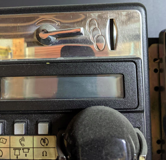
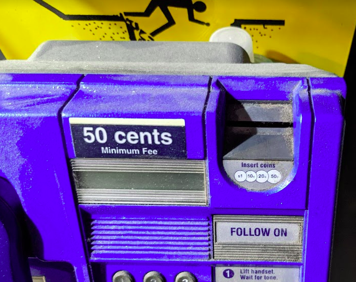
Let’s imagine the coin slot on a payphone – Coins can only enter the slot if they’re aligned with the slot.
If you tried to rotate the coin by 90 degrees, it wouldn’t fit it in the slot.
If the slot on the payphone went from up-to-down, our coin slot could be described as “vertically polarized”. Only coins in the vertically polarized orientation would fit.
Likewise, a payphone with the coin slot going side-to-side we could describe the coin slot as being “horizontally polarized”, meaning only coins that are horizontally polarized (on their side) would fit into the coin slot.
RF waves also have a polarization, like our coin slot.
A receiver wishing to receive into signals transmitted from a vertically-polarized antenna, will need to use a vertically-polarised antenna to pick up the signal.
Likewise a signal transmitted from a horizontally polarized antenna, would require a horizontally polarised antenna on the receiving side.
If there is a mismatch in polarization (for example RF waves transmitted from a horizontal polarized antenna but the receiver is using a vertically polarized antenna) the signal may still get through, but received signal strength would be severely degraded – in the order of 20dB, which is 1/100th of the power you’d get with the correct polarization.
You can think of polarization mismatches as like cutting up the coin to fit sideways through the coin slot – you’d get a sliver of the original coin that was cut up to fit. Much like you recieve a fraction of the original signal if your polarization doesn’t match on both ends.
Plagiarised diagram showing antenna polarization
Useless Information: In Australia country TV stations and metro TV stations sometimes transmitted different programming. To differentiate the signals on the receiver side, country TV transmitters used vertical polarisation, while metro transmitters used horizontal polarization. The use of different polarization orientation cuts down on interference in the border areas that sit in the footprint of the metro and country transmitters. This means as you drive through metro areas you’ll see all the yagi-antennas are horizontally oriented, while in country areas, they’re vertically oriented.
Vertical Polarization
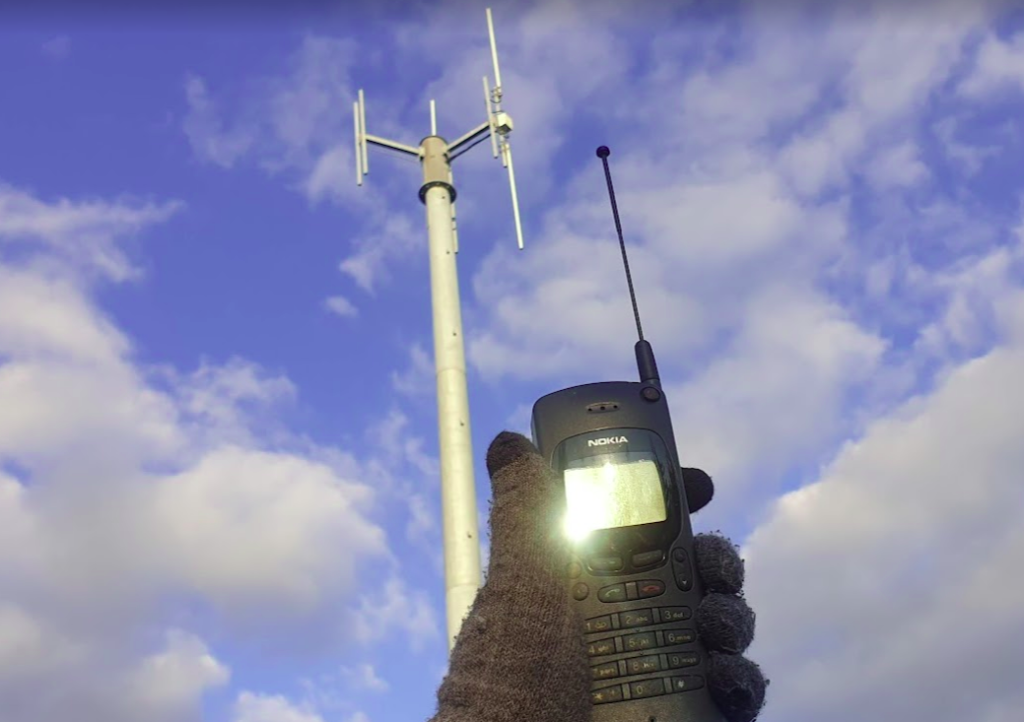
Early mobile phone networks used Vertical Polarization.
This means they used an flagpole like antenna that is vertically oriented (Omnidirectional antenna) on the base-station sites.
Oldschool mobile phones also had a little pop out omnidirectional antenna, which when you held the phone to your ear, would orient the antenna vertically.
This matches with the antenna on the base station, and away we go. You still sometimes see vertical polarization in use on base-station sites in low density areas, or small cells.
Vertically polarized mobile phone antenna, which is oriented vertically, like on the base station behind it.
Increasing subscriber demand meant that operators needed more capacity in the network, but spectrum is expensive. As we just saw a mismatch in polarization can lead to a huge reduction in power, and maybe we can use that to our advantage…
Shannon-Hartley Theorem
But first, we need to do some maths…
Stick with me, this won’t be that hard to understand I promise.
There are two factors that influence the capacity of a network, the Bandwidth of the Channel and the Signal-to-Noise Ratio.
So let’s look at what each of these terms mean.
Bandwidth
Bandwidth is the information carrying capacity. A one-page sheet of A4 at 12 point font, has a set bandwidth. There’s only so much text you can fit on one A4 sheet at that font size.
A4 Sheet, 12 point font, has 989 words.
We can increase the bandwidth two ways:
Option 1 to Increase Bandwidth: Get a larger transmission medium. Changing the size of the medium we’re working with, we can increase how much data we can transfer.
For this example we could get a bigger sheet of paper, for example an A3 sheet, or a billboard, will give us a lot more bandwidth (content carrying capability) than our sheet of A4.
Changing from an A4 sheet to an A3 sheet, increases the number of characters we can store on the page (Slightly more than doubling the bandwidth).
Option 2 to Increase Bandwidth: Use more efficient encoding As well as changing the size of the medium we are using, we can change how we store the data on the paper, for example, shrinking the font size to get more text in the same area, which also the bandwidth.
In communications networks this is also true: Bandwidth is determined by how much spectrum we have to work with (For example 10Mhz), and how we encode the data on that spectrum, ie morse-code, Binary-Phase-Shift-Keying or 16-QAM. Each of the different encoding schemes have different levels of bandwidth for the same amount of spectrum used, and we’ll cover those in more detail in the future.
So now we’ve covered increasing the bandwidth, now let’s talk about the other factor:
Signal-to-Noise Ratio
Signal-to-NoiseRatio (SNR) is the ratio of good signal, to the background noise.
On the train my headphones on block out most of the other sounds. In this scenario, the signal (the podcast I’m listening to on the headphones) is quite high, compared to the noise (unwanted sounds of other people on the train), so I have a good Signal-to-Noise ratio.
When we talk about the Signal-to-Noise Ratio, we’re talking about the ratio of the signal we want (podcast) to the noise (signal we don’t want).
When I’m on the train if 90% of what I hear is the podcast I’m listening to (the “signal”) and 10% is random background sounds (the “noise”) then my signal-to-noise-ratio is really good (high).
Capacity and SNR
Let’s continue with the listening to a podcast analogy.
The average human talks about 150 words per minute. So let’s imagine I’m listening to a podcast at 150 words per minute.
If I’m listening in an anechoic chamber, then I’ll be able to hear everything that’s being said, so my bandwidth will 150 words per minute. As there is no background noise, my capacity will also be 150 words per minute.
But if I leave an anechoic chamber (much as I love spending time in anechoic chambers), and go back on the train, I won’t hear the full 150 words per minute (bandwidth) due to the noise on the train drowning out some of the signal (podcast).
The Shannon-Hartley Theorem, states that the capacity is equal to the bandwidth multiplied by the signal to noise ratio.
So on the train hearing 90% of what’s said on the podcast, 10% drowned out, means my signal-to-noise ratio is 0.9 (pretty good).
So according to Shannon-Hartley Theorem the capacity of me listening to a podcast on the train (150 words per minute of bandwidth multiplied by 0.9 Signal-to-Noise Ratio) would give me 135 words per minute of capacity.
Claude Shannon, of 1/2 of the Shannon-Hartley Theorem, with an electromechanical mouse maze.
How this applies to RF Networks
In an RF context, our Bandwidth has a fixed information carrying capacity, for example on LTE, with a 5Mhz wide channel using 16QAM has 12.5Mbps of bandwidth available.
In a simple system, we have two levers we can pull to increase the bandwidth:
Increasing the size of the channel – If we went from a 5Mhz wide channel to a 20Mhz channel, this would give us 4x the available Bandwidth (Actually slightly more in LTE, but whatever)
Changing the encoding to cram more data on the same a size channel (From 16QAM to 64QAM would also give us 4x the available Bandwidth).
As we’ll see later in this post, there are some extra tricks (MIMO and Diversity) that we’ll look at later in this post, to increase the bandwidth of the system.
Our Signal-To-Noise (SNR) is constantly variable with a gazillion things that can influence the result. Some of the key factors that impact the SNR are the distance from the transmitter to the receiver and anything blocking the path between them (trees, buildings, mountains, etc), but there’s so many other factors that go into this. From atmospheric conditions, flat surfaces the signal can reflect off leading to multipath noise, other nearby transmitters, etc, can all influence our SNR.
Our capacity is equal to our Bandwidth multiplied by the Signal-to-Noise ratio.
Shannon-Hartley Theorem (ish)
As a goal we want capacity, and in an ideal world, our capacity would be equal to our bandwidth, but all that noise sneaks in and reduces our available capacity, based on the current SNR value.
So now we want to get more capacity out of the network, because everyone always wants to add capacity to networks.
One trick that we can use it to use multiple antennas with different polarization.
If our transmitter sends the same signal data out multiple antennas, with some clever processing on the transmitter and the receiver, we use this to maximize the received SNR. This is called Transmit Diversity and Receive Diversity and it’s a form of black magic.
The Transmitter uses feedback from the receiver to determine what the channel conditions are like, and then before transmitting the next block of data, compensates for the channel conditions experienced by the receiver, this increases the SNR and allows for higher MCS / encoding schemes, which in turns means higher throughput.
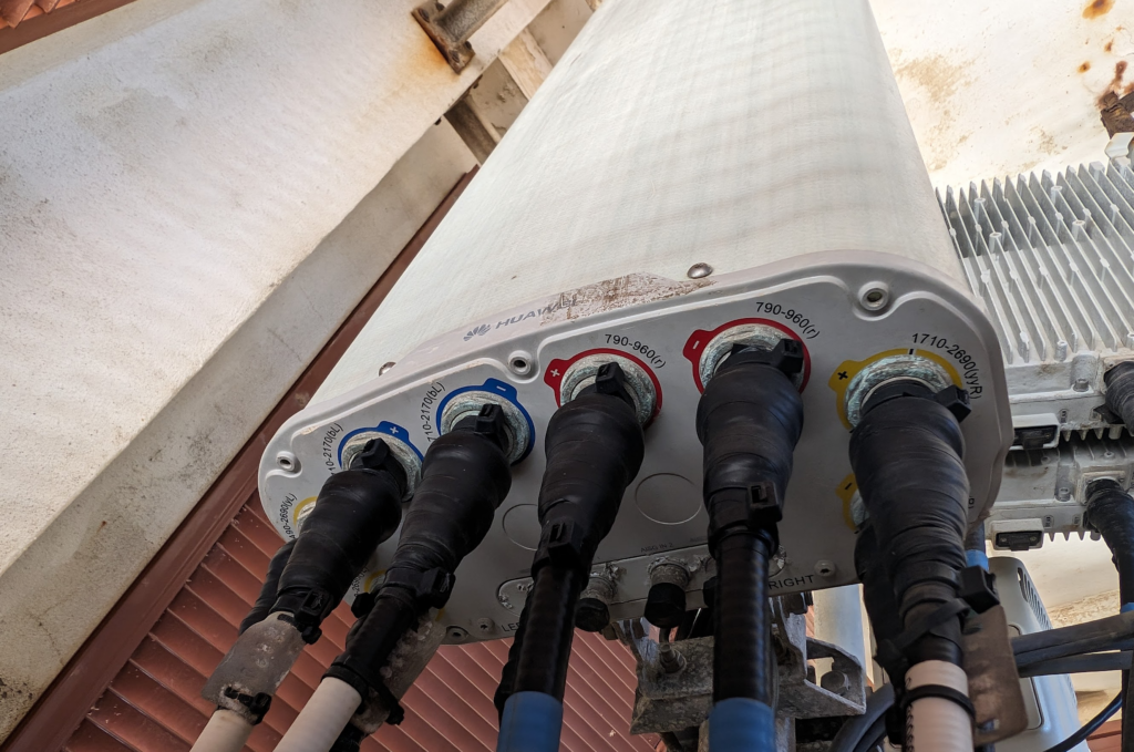
You’ll notice on most Antennas in the wild today you’ve got at least two ports for each frequency, which are + and -, which are the two polarizations.
Modern mobile networks use ±45° slant polarization (aka X Polarization), which works better in the orientations end users hold their phones in.
These two polarizations, each connected to a distinct transmit/receive path on the phone (UE) end and on the base station end, allows multiple data streams to be sent at the same time (spatial multiplexing, the foundation for MIMO) which enables higher throughput or can be configured enable redundancy in the transmission to better pick up weak signals (Diversity).
Technology is constantly evolving, new research papers are published every day.
But recently I was shocked to discover I’d missed a critical development in communications, that upended Shannon’s “A mathematical theory of communication”.
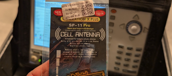
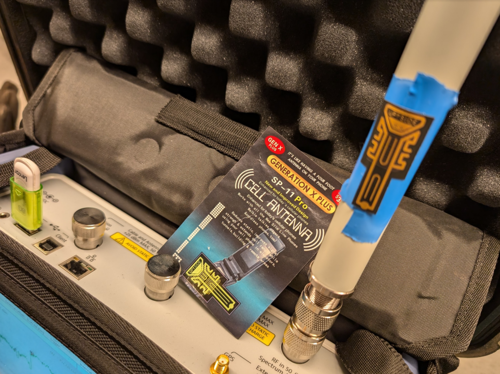
I’m talking of course, about the GENERATION X PLUS SP-11 PRO CELL ANTENNA.
I’ve been doing telecom work for a long time, while I mostly write here about Core & IMS, I am a licenced rigger, I’ve bolted a few things to towers and built my fair share of mobile coverage over the years, which is why I found this development so astounding.
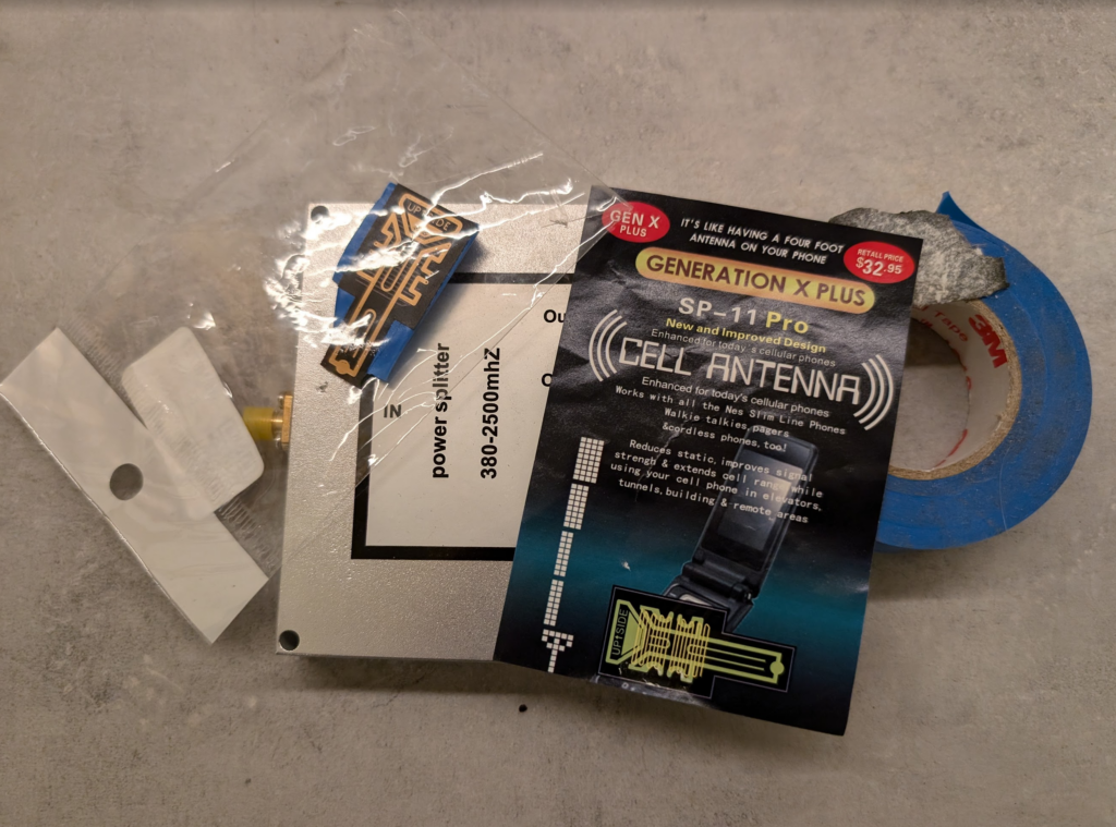
With this, existing antennas can be extended, mobile phone antennas, walkie talkies and cordless phones can all benefit from the improvement of this small adhesive sticker, which is “Like having a four foot antenna on your phone”.
So for the bargain price of $32.95 (Or $2 on AliExpress) I secured myself this amazing technology and couldn’t wait to quantify it’s performance.
Think of the applications – We could put these stickers on 6 ft panel antennas and they’d become 10ft panels. This would have a huge effect on new site builds, minimize wind loading, less need for tower strengthening, more room for collocation on the towers due to smaller equipment footprint.
Luckily I have access to some fancy test equipment to really understand exactly how revolutionary this is.
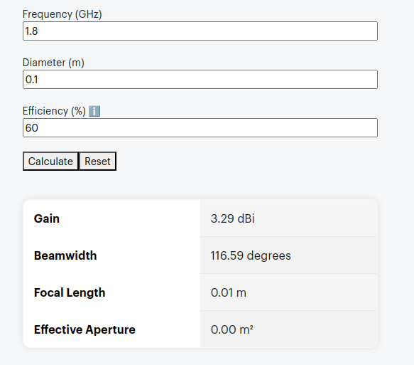
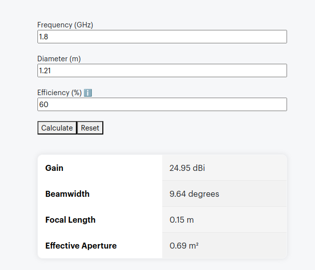
The packaging says it’s like having a 4 foot antenna on your phone, let’s do some very simple calculations, let’s assume the antenna in the phone is currently 10cm, and that with this it will improve to be 121cm (four feet).
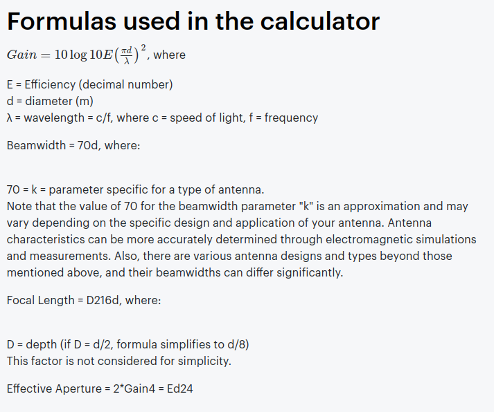
Projected Gain (Post Sticker)Formulas Used
According to some basic projections we should see ~21dB gain by adding the sticker, that’s a 146x increase in performance!
Man am I excited to see this in action.
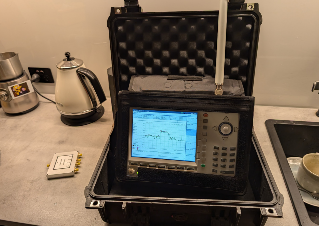
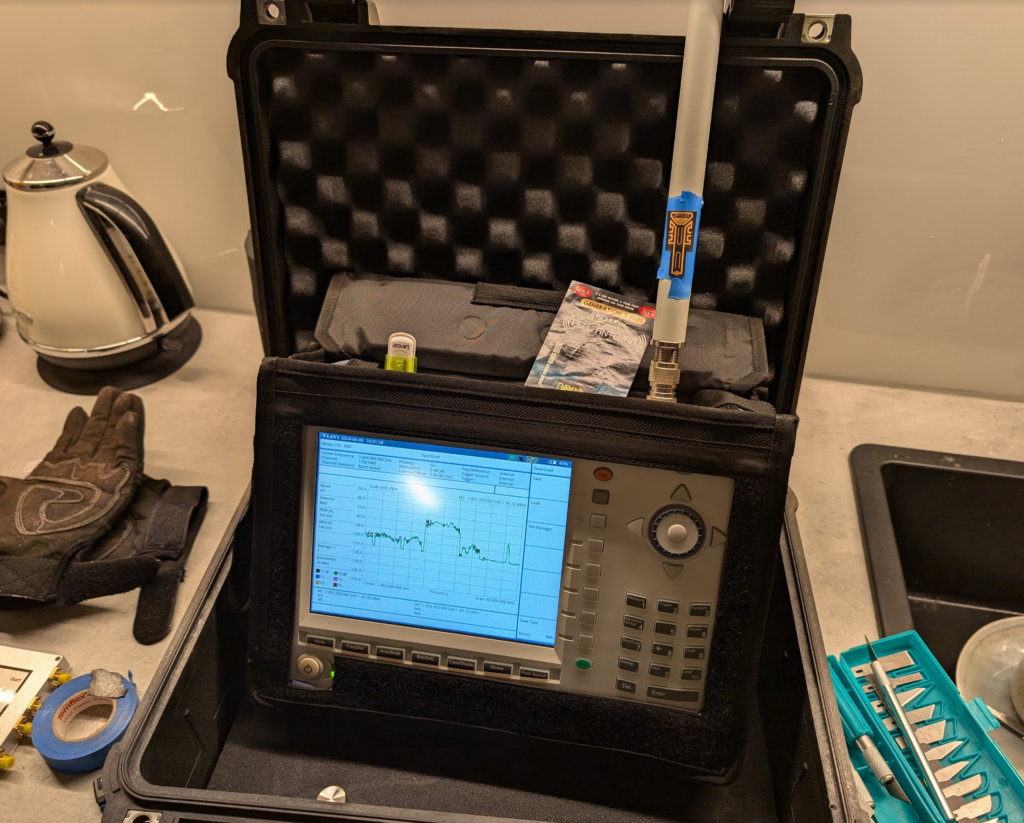
Fortunately I have access to some fun cellular test equipment, including the Viavi CellAdvisor and an environmentally controlled lab my kitchen bench.
I put up a 1800Mhz (band 3) LTE carrier in my office in the other room as a reference and placed the test equipment into the test jig (between the sink and the kettle).
We then took baseline readings from the omni shown in the pictures, to get a reading on the power levels before adding the sticker.
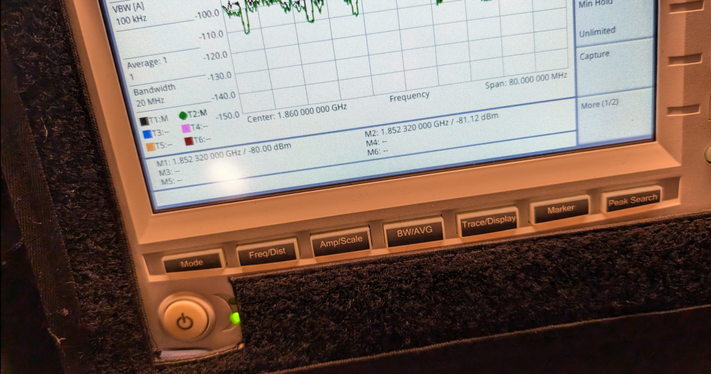
We are reading exactly -80dBm without the sticker in place, so we expertly put some masking tape on the omni (so we could peel it off) and applied the sticker antenna to the tape on the omni antenna.
At -80dBm before, by adding the 21dB of gain, we should be put just under -60dBm, these Viavi units are solid, but I was fearful of potentially overloading the receive end from the gain, after a long discussion we agreed at these levels it was unlikely to blow the unit, so no in-line attenuation was used.
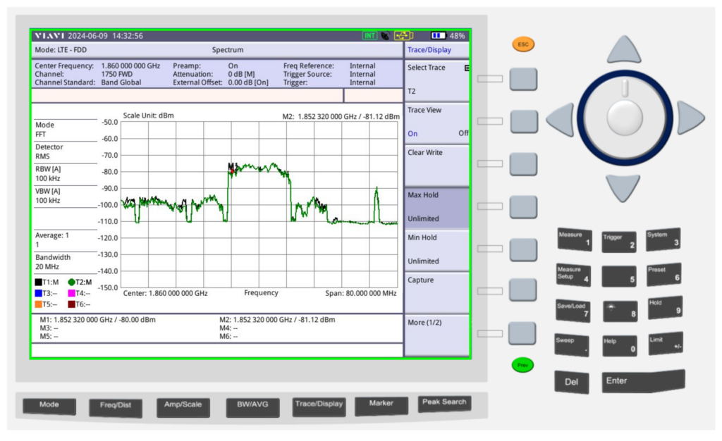
Okay, </sarcasm> I was genuinely a little surprised by what we found; there was some gain, as shown in the screenshot below.
Marker 1 was our reference without the sticker, while reference 2 was our marker with the sticker, that’s a 1.12dB gain with the sticker in place. In linear terms that’s a ~30% increase in signal strength.
Screenshot
So does this magic sticker work? Well, kinda, in as much that holding onto the Omni changes the characteristics, as would wrapping a few turns of wire around it, putting it in the kettle or wrapping it in aluminum foil. Anything you do to an antenna to change it is going to cause minor changes in characteristic behavior, and generally if you’re getting better at one frequency, you get worse at another, so the small gain on band 3 may also lead to a small loss on band 1, or something similar.
So what to make of all this? Maybe this difference is an artifact from moving the unit to make a cup of tea, the tape we applied or just a jump in the LTE carrier, or maybe the performance of this sticker is amazing after all…
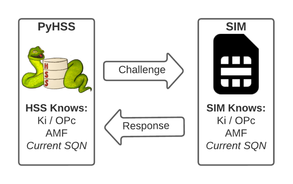
I’ve written about Milenage and SIM based security in the past on this blog, and the component that prevents replay attacks in cellular network authentication is the Sequence Number (Aka SQN) stored on the SIM.
Think of the SQN as an incrementing odometer of authentication vectors. Odometers can go forward, but never backwards. So if a challenge comes in with an SQN behind the odometer (a lower number), it’s no good.
Why the SQN is important for Milenage Security
Every time the SIM authenticates it ticks up the SQN value, and when authenticating it checks the challenge from the network doesn’t have an SQN that’s behind (lower than) the SQN on the SIM.
Let’s take a practical example of this:
The HSS in the network has SQN for the SIM as 8232, and generates an authentication challenge vector for the SIM which includes the SQN of 8232. The SIM receives this challenge, and makes sure that the SQN in the SIM, is equal to or less than 8232. If the authentication passes, the new SQN stored in the SIM is equal to 8232 + 1, as that’s the next valid SQN we’d be expecting, and the HSS incriments the counters it has in the same way.
By constantly increasing the SQN and not allowing it to go backwards, means that even if we pre-generated a valid authentication vector for the SIM, it’d only be valid for as long as the SQN hasn’t been authenticated on the SIM by another authentication request.
Imagine for example that I get sneaky access to an operator’s HSS/AuC, I could get it to generate a stack of authentication challenges that I could use for my nefarious moustache-twirling purposes whenever I wanted.
This attack would work, but this all comes crumbling down if the SIM was to attach to the real network after I’ve generated my stack of authentication challenges.
If the SQN on the SIM passes where it was when the vectors were generated, those vectors would become unusable.
It’s worth pointing out, that it’s not just evil purposes that lead your SQN to get out of Sync; this happens when you’ve got subscriber data split across multiple HSSes for example, and there’s a mechanism to securely catch the HSS’s SQN counter up with the SQN counter in the SIM, without exposing any secrets, but it just ticks the HSS’s SQN up – It never rolls back the SQN in the SIM.
The Flaw – Draining the Pool
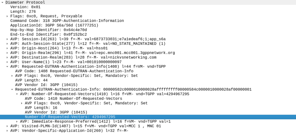
The Authentication Information Request is used by a cellular network to authenticate a subscriber, and the Authentication Information Answer is sent back by the HSS containing the challenges (vectors).
When we send this request, we can specify how many authentication challenges (vectors) we want the HSS to generate for us, so how many vectors can you generate?
TS 129 272 says the Number-of-Requested-Vectors AVP is an Unsigned32, which gives us a possible pool of 4,294,967,295 combinations. This means it would be legal / valid to send an Authentication Information Request asking for 4.2 billion vectors.
It’s worth noting that that won’t give us the whole pool.
Sequence numbers (SQN) shall have a length of 48 bits.
TS 133 102
While the SQN in the SIM is 48 bits, that gives us a maximum number of values before we “tick over” the odometer of 281,474,976,710,656.
If we were to send 65,536 Authentication-Information-Requests asking for 4,294,967,295 a piece, we’d have got enough vectors to serve the sub for life.
Except the standard allows for an unlimited number of vectors to be requested, this would allow us to “drain the pool” from an HSS to allow every combination of SQN to be captured, to provide a high degree of certainty that the SQN provided to a SIM is far enough ahead of the current SQN that the SIM does not reject the challenges.
Can we do this?
Our lab has access to HSSes from several major vendors of HSS.
Out of the gate, the Oracle HSS does not allow more than 32 vectors to be requested at the same time, so props to them, but the same is not true of the others, all from major HSS vendors (I won’t name them publicly here).
For the other 3 HSSes we tried from big vendors, all eventually timed out when asking for 4.2 billion vectors (don’t know why that would be *shrug*) from these HSSes, it didn’t get rejected.
This is a lab so monitoring isn’t great but I did see a CPU spike on at least one of the HSSes which suggests maybe it was actually trying to generate this.
Of course, we’ve got PyHSS, the greatest open source HSS out there, and how did this handle the request?
Well, being standards compliant, it did what it was asked – I tested with 1024 vectors I’ll admit, on my little laptop it did take a while. But lo, it worked, spewing forth 1024 vectors to use.
So with that working, I tried with 4,294,967,295…
And I waited. And waited.
And after pegging my CPU for a good while, I had to get back to real life work, and killed the request on the HSS.
In part there’s the fact that PyHSS writes back to a database for each time the SQN is incremented, which is costly in terms of resources, but also that generating Milenage vectors in LTE is doing some pretty heavy cryptographic lifting.
The Risk
Dumping a complete set of vectors with every possible SQN would allow an attacker to spoof base stations, and the subscriber would attach without issue.
Historically this has been very difficult to do for LTE, due to the mutual network authentication, however this would be bypassed in this scenario.
The UE would try for a resync if the SQN is too far forward, which mitigates this somewhat.
Cryptographically, I don’t know enough about the Milenage auth to know if a complete set of possible vectors would widen the attack surface to try and learn something about the keys.
Mitigations / Protections
So how can operators protect ourselves against this kind of attack?
Different commercial HSS vendors handle this differently, Oracle limits this to 32 vectors, and that’s what I’ve updated PyHSS to do, but another big HSS vendor (who I won’t publicly shame) accepts the full 4294967295 vectors, and it crashes that thread, or at least times it out after a period.
If you’ve got a decent Diameter Routing Agent in place you can set your DRA to check to see if someone is using this exploit against your network, and to rewrite the number of requested vectors to a lower number, alert you, or drop the request entirely.
Having common OP keys is dumb, and I advocate to all our operator customers to use OP keys that are unique to each SIM, and use the OPc key derived anyway. This means if one SIM spilled it’s keys, the blast doesn’t extend beyond that card.
In the long term, it’d be good to see 3GPP limit the practical size of the Number-of-Requested-Vectors AVP.
2G/3G Impact
Full disclosure – I don’t really work with 2G/3G stacks much these days, and have not tested this.
MAP is generally pretty bandwidth constrained, and to transfer 280 billion vectors might raise some eyebrows, burn out some STPs and take a long time…
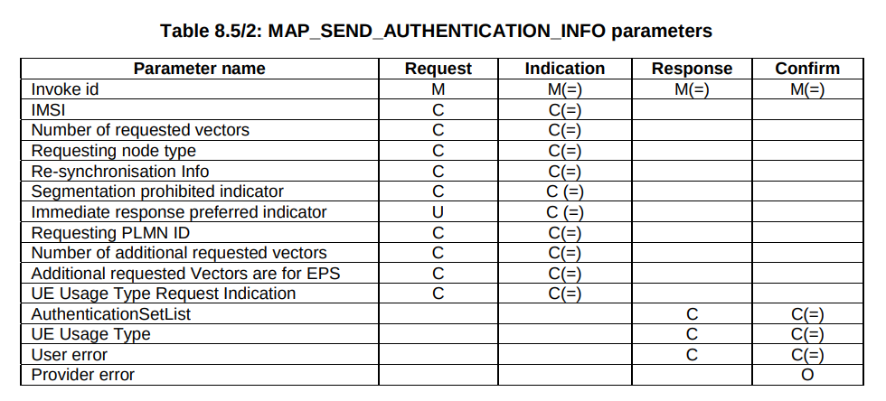
But our “Send Authentication Info” message functions much the same as the Authentication Information Request in Diameter, 3GPP TS 29.002 shows we can set the number of vectors we want:
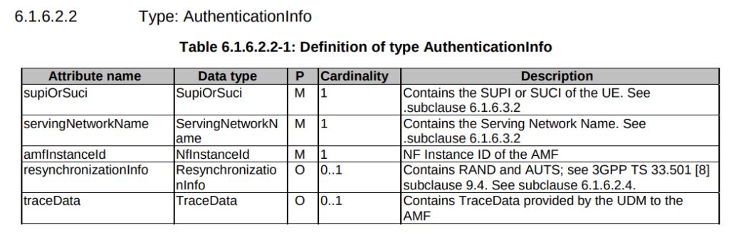
5GC Vulnerability
This only impacts LTE and 5G NSA subscribers.
TS 29.509 outlines the schema for the Nausf reference point, used for requesting vectors, and there is no option to request multiple vectors.
Summary
If you’ve got baddies with access to your HSS / HLR, you’ve got some problems.
But, with enough time, your pool could get drained for one subscriber at a time.
This isn’t going to get the master OP Key or plaintext Ki values, but this could potentially weaken the Milenage security of your system.
One of the new features of 5GC is the introduction of Service Based Interfaces (SBI) which is part of 5GC’s Service Based Architecture (SBA).
Let’s start with the description from the specs:
3GPP TS 23.501 [3] defines the 5G System Architecture as a Service Based Architecture, i.e. a system architecture in which the system functionality is achieved by a set of NFs providing services to other authorized NFs to access their services.
3GPP TS 29.500 – 4.1 NF Services
For that we have two key concepts, service discovery, and service consumption
Services Consumer / Producers
That’s some nice words, but let’s break down what this actually means, for starters, let’s talk about services.
In previous generations of core network we had interfaces instead of services. Interfaces were the reference point between two network elements, describing how the two would talk. The interfaces were the protocols the two interfaces used to communicate.
For example, in EPC / LTE S6a is the interface between the MME and the HSS, S5 is the interface between the S-GW and P-GW. You could lookup the 3GPP spec for each interface to understand exactly how it works, or decode it in Wireshark to see it in action.
5GC moves from interfaces to services. Interfaces are strictly between two network elements, the S6a interface is only used between the MME and the HSS, while a service is designed to be reusable.
This means the Service Based Interface N5g-eir can be used by the AMF, but it could equally be used by anyone else who wants access to that information.
3GPP defines the service in the form of service producer (The EIR produces the N5g-eir service) and the service consumer (The client connecting to the N5g-eir service), but doens’t restrict which network elements can
This gets away from the soup of interfaces available, and instead just defines the services being offered, rather than locking the
“service consumers” (which can be thought of clients in a client/server model) can discover “service producers” (like servers in a client/server model).
Our AMF, which acts as a “service consumer” consuming services from the UDM/UDR and SMF.
Service Discovery – Automated Discovery of NF Services
Service-Based Architecture enables 5G Core Network Function service discovery.
In simple terms, this means rather that your MME being told about your SGW, the nodes all talk to a “Network Repository Function” that returns a list of available nodes.
The mobility management and connection management process in 5GC focuses on Connection Management (CM) and Registration Management (RM).
Registration Management (RM)
The Registration Management state (RM) of a UE can either be RM-Registered or RM-Deregistered. This is akin to the EMM state used in LTE.
RM-Deregistered Mode
From the Core Network’s perspective (Our AMF) a UE that is in RM-Deregistered state has no valid location information in the AMF for that UE. The AMF can’t page it, it doesn’t know where the UE is or if it’s even turned on.
From the UE’s perspective, being in RM-Deregistered state could mean one of a few things:
UE is in an area without coverage
UE is turned off
SIM Card in the UE is not permitted to access the network
In short, RM-Deregistered means the UE cannot be reached, and cannot get any services.
RM-Registered Mode
From the Core Network’s perspective (the AMF) a UE in RM-Registered state has sucesfully registered onto the network.
The UE can perform tracking area updates, period registration updates and registration updates.
There is a location stored in the AMF for the UE (The AMF knows at least down to a Tracking Area Code/List level where the UE is).
The UE can request services.
Connection Management (CM)
Connection Management (CM) focuses on the NAS signaling connection between the UE and the AMF.
To have a Connection Management state, the Registration Management procedure must have successfully completed (the UE being in RM-Registered) state.
A UE in CM-Connected state has an active signaling connection on the N1 interface between the UE and the AMF.
CM-Idle Mode
In CM-Idle mode the UE has no active NAS connection to the AMF.
UEs typically enter this state when they have no data to send / recieve for a period of time, this conserves battery on the UE and saves network resources.
If the UE wants to send some data, it performs a Service Request procedure to bring itself back into CM-Connected mode.
If the Network wants to send some data to the UE, the AMF sends a paging request for the UE, and upon hearing it’s identifier (5G-S-TMSI) on the paging channel, the UE performs the Service Request procedure to bring itself back into CM-Connected mode.
CM-Connected Mode
In CM-Connected mode the UE has an active NAS connection with the AMF over the N1 interface from the UE to the AMF.
When the access network (The gNodeB) determines this state should change (typically based on the UE being idle for longer than a set period of time) the gNodeB releases the connection and the UE transitions to CM-Idle Mode.
So let’s roll up our sleeves and get a Lab scenario happening,
To keep things (relatively) simple, I’ve put the eNodeB on the same subnet as the MME and Serving/Packet-Gateway.
So the traffic will flow from the eNodeB to the S/P-GW, via a simple Network Switch (I’m using a Mikrotik).
While life is complicated, I’ll try and keep this lab easy.
Experiment 1: MTU of 1500 everywhere
Network Element
MTU
Advertised MTU in PCO
1500
eNodeB
1500
Switch
1500
Core Network (S/P-GW)
1500
So everything attaches and traffic flows fine. There is no problem right?
Well, not a problem that is immediately visible.
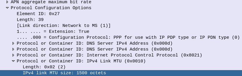
While the PCO advertises the MTU value at 1500 if we look at the maximum payload we can actually get through the network, we find that’s not the case.
This means if our end user on a mobile device tried to send a 1500 byte payload, it’d never get through.
While DNS would work, most TCP traffic would flow fine, certain UDP applications would start to fail if they were sending payloads nearing 1500 bytes.
So why is this?
Well GTP adds overhead.
8 bytes for the GTP header
8 bytes for the transport UDP header
20 bytes for the transport IPv4 header
14 bytes if our transport is using Ethernet
For a total of 50 bytes of overhead, assuming we’re not using MPLS, QinQ or anything else funky on our transport network and just using Ethernet.
So we have two options here – We can either lower the MTU advertised in our Protocol Configuration Options, or we can increase the MTU across our transport network. Let’s look at each.
Experiment 2: Lower Advertised MTU in PCO to 1300
Well this works, and looks the same as our previous example, except now we know we can’t handle payloads larger than 1300 without fragmentation.
Experiment 3: Increase MTU across transmission Network
While we need to account for the 50 bytes of overhead added by GTP, I’ve gone the safer option and upped the MTU across the transport to 1600 bytes.
With this, we can transport a full 1500 byte MTU on the UE layer, and we’ve got the extra space by enabling jumbo frames.
Obviously this requires a change on all of the transmission layer – And if you have any hops without support for this, you’ll loose packets.
Conclusions?
Well, fragmentation is bad, and we want to avoid it.
For this we up the MTU across the transmission network to support jumbo frames (greater than 1500 bytes) so we can handle the 1500 byte payloads that users want.
This post follows on from Part 1 and Part 2 of this 3 part series.
We are forced to move to 5G-SA
Claim: We must use 5G-SA with this spectrum (It’s a condition of the license)
I’ll concede that if it is a requirement for a license or funding, that 5G-SA be used, then that’s a pretty ironclad reason to introduce 5G-SA.
Claim: Users will Leave if you don’t have 5G-SA
We could argue the opposite effect will happen; Shifting to SA will reduce your user base. Here’s why:
Users experiencing 5G-NSA (Non-Standalone) today, are already getting the speed boost from “5G”.
From a user perspective, while 5G-NSA support has been becoming common on mid-to-high priced handsets, handsets supporting 5G-SA are far less common.
Dish’ Project Genesis is one of the only examples of a 5G SA network deployed on a large scale. It launched with only a single supported phone (A Motorola branded handset) and today the supported phone list is very short, limited to expensive flagships. This lack of handset support means users must purchase a handset through Dish rather than being able to bring their own phones, as the only way that compatibility can be guaranteed is by controlling the whole ecosystem.
Unless you are in a highly developed market with 2G and 3G turned off, where the majority of your user base has recent generation flagship phones capable of supporting these features, you’re shrinking your addressable market with 5G-SA, rather than expanding it.
Conclusion – 5G-SA doesn’t stack up, what do I do?
SA doesn’t make sense for a lot of operators and markets – for now. I’m sure this post will look pretty dated in a few years time as many of these factors change and as operators sunset 2G and 3G networks.
I’m not advocating for 5G-SA never, I’m advocating not 5G-SA today.
There are simply better options out there for spending that operations budget to make network improvements.
Off the bat some ideas to expore:
Optimize your existing network.
Roll out NSA to an even larger area.
Shutdown 2G/3G layers.
Simplify your operations.
Cut down the number of vendors and moving parts.
Simplify again.
Automate.
Simplify more.
Doing this will mean you can enjoy cost savings from reduced headcount thanks to a simpler network. Simpler networks have better up-time, thanks to operating a network that’s less frankensteiny – less cobbled together from disparate legacy parts. You’ll also Enjoy reduced opex from all the systems you’ve shut down and cheaper roaming from all the bilaterals you moved to VoLTE.
All of these tasks will keep project teams busy for years and put the MNO in a stronger position moving forward, without getting distracted by slick marketing and shiny brochures.
To make more Money (This post, congratulations, you’re reading it!)
Because they have to (Regulatory compliance, insurance, taxes, etc) – That’s the next post
So let’s look at SA in this context.
5G-SA can drive new revenue streams
We (as an industry) suck at this.
Last year on the Telecoms.com podcast, Scott Bicheno made the point that if operators took all the money they’d gambled (and lost) on trying to play in the sports rights, involvement in media companies, building their own streaming apps, attempts at bundling other utilities, digital identity, etc, and just left the cash in the bank and just operated the network, they’d be better off.
Uber, Spotify, “OTTs”, etc, utilize MNOs to enable their services, but operators don’t see this extra revenue. While some operators may talk of “fair share” the truth is, these companies add value to our product (connectivity) which as an industry, we’ve failed to add ourselves.
If the Metaverse does turn out to be a cash cow, it is unlikely the telecommunications industry will be the ones milking it.
Claim: Customers are willing to pay more for 5G-SA
This myth seems to be fairly persistent, but with minimal data to support this claim.
While BSS vendors talk about “5G Monetization”, the truth is, people use their MNO to provide them connectivity. If the coverage is adequate, and the speed enough to do what they need to do, few would be willing to pay any additional cash each month to see higher numbers on a speedtest result (enabled by 5G-NSA) and even fewer would pay extra cash for, well, whatever those features only enabled by 5G-Standalone are?
With most consumers now also holding onto their mobile devices for longer periods of time, and with interest rates reining in consumer spending across the board, we are seeing the rise of a more cost conscious consumer than ever before. If we want to see higher ARPUs, we need to give the consumer a compelling reason to care and spend their cash, beyond a speed test result.
We talk a little about APIs lower down in the post.
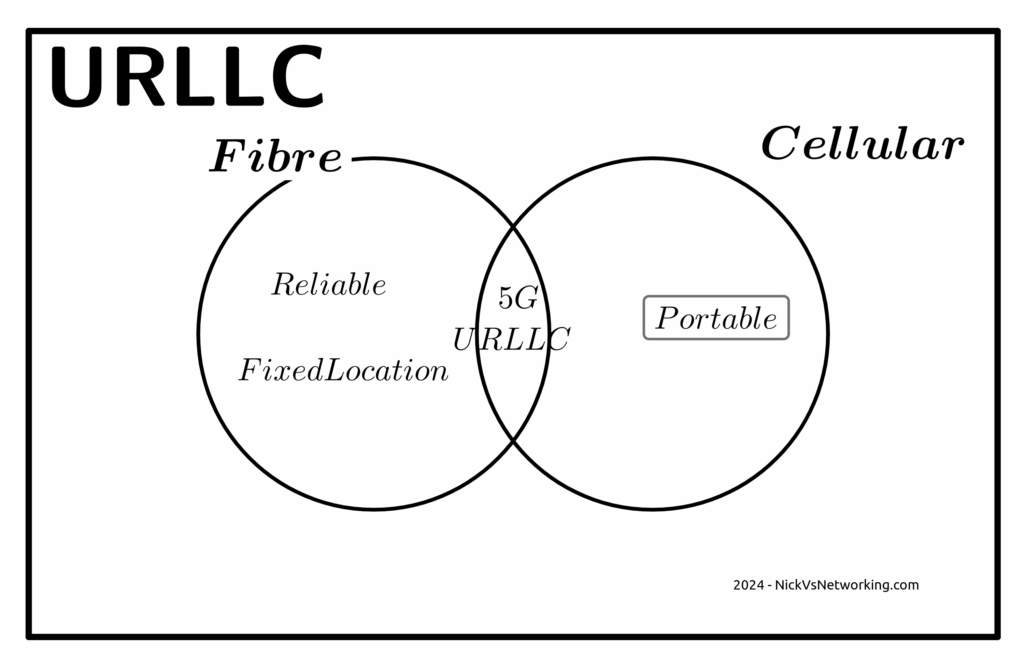
Claim: Users want Ultra-Low Latency / High Reliability Comms that only 5G-SA delivers
Wanting to offer a product to the market, is not the same as the market wanting a product to consume.
Telecom operators want customers to want these services, but customer take up rates tell a different story. For a product like this to be viable, it must have a wide enough addressable market to justify the investment.
Reliability
The URLCC standards focus on preventing packet loss, but the world has moved on from needing zero packet loss.
The telecom industry has a habit of deciding what customers want without actually listening. When a customer talks about wanting “reliable” comms, they aren’t saying they want zero packet loss, but rather fewer dropouts or service flaps. For us to give the customer what they are actually asking for involves us expanding RAN footprint and adding transmission diversity, not 5G-SA.
The “protocols of the internet” (TCP/IP) have been around for more than 50 years now.
These protocols have always flowed over transport links with varied reliability and levels of packet loss.
Thanks to these error correction and retransmission techniques built into these protocols, a lost packet will not interrupt the stream. If your nuclear command and control network were carried over TCP/IP over the public internet (please don’t do this), a missing packet won’t lead to worldwide annihilation, but rather the sender will see the receiver never acknowledged the receipt of the packet at the other end, and resend it, end of.
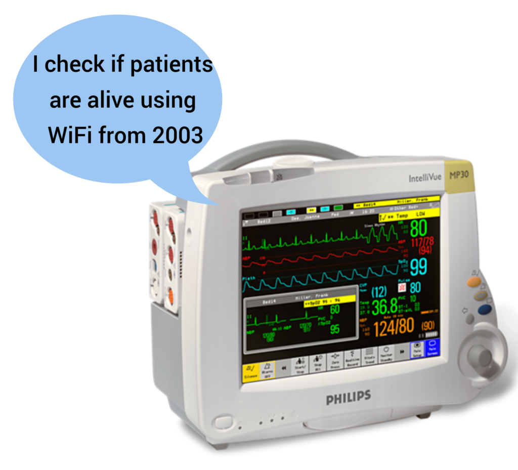
If you walk into a hospital today, you’ll find patient monitoring devices, tracking the vital signs for patients and alerting hospital staff if a patient’s vital signs change. It is hard to think of more important services for reliability than this.
And yet they use WiFi, and have done for a long time, if a packet is lost on WiFi (as happens regularly) it’s just retransmitted and the end user never knows.
Autonomous cars are unlikely to ever rely on a 5G connection to operate, for the simple reason that coverage will never be 100%. If your car stops because you’re in a not-spot, you won’t be a happy customer. While plenty of cars have cellular modems in them, that are used to upload telemetry data back to the manufacturer, but not to drive the car.
One example of wireless controlled vehicles in the wild is autonomous haul trucks in mines. Historically, these have used WiFi for their comms. Mine sites are often a good fit for Private LTE, but there’s nothing inherent in the 5G Standalone standard that means it’s the only tool for the job here.
Slicing
Slicing is available in LTE (4G), with an architecture designed to allow access to others. It failed to gain traction, but is in networks today.
The RAN a piece of the latency puzzle here, but it is just one piece of the puzzle.
If we look at the flow a packet takes from the user’s device to the server they want to talk to we’ve got:
Time it takes the UE to craft the packet
Time it takes for the packet to be transmitted over the air to the base station
Time it takes for the packet to get through the RAN transmission network to the core
Time it takes the packet to traverse the packet core
Time it takes for the packet to get out to transit/peering
Time it takes to get the packet from the edge of the operators network to the edge of the network hosting the server
Time it takes the packet through the network the server is on
Time it takes the server to process the request
The “low latency” bit of the 5G puzzle only involves the two elements in bold.
If you’ve got to get from point A to point B along a series of roads, and the speed limit on two of the roads you traverse (short sections already) is increased. The overall travel time is not drastically reduced.
I’m lucky, I have access to a well kitted out lab which allows me to put all of these latency figures to the test and provide side by side metrics. If this is of interest to anyone, let me know. Otherwise in the meantime you’ll just have to accept some conjecture and opinion.
You could rebut this talking about Edge Compute, and having the datacenter at the base of the tower, but for a number of fairly well documented reasons, I think this is unlikely to attract widespread deployment in established carrier networks, and Intel’s recent yearly earning specifically called this out.
Claim: Customers want APIs and these needs 5G SA
Companies like Twilio have made it easy to interact with the carrier network via their APIs, but yet again, it’s these companies producing the additional value on a service operated by the MNOs.
My coffee machine does not have an API, and I’m OK with this because I don’t have a want or need to interact with it programatically.
By far, the most common APIs used by businesses involving telco markets are APIs to enable sending an SMS to a user.
These have been around for a long time, and the A2P market is pretty well established, and the good news is, operators already get a chunk of this pie, by charging for the SMS.
Imagine a company that makes medical booking software. They’re a tech company, so they want their stack to work anywhere in the world, and they want to be able to send reminder SMS to end users.
They could get an account manager with each of the telcos in each of the markets they work in, onboard and integrate the arcane complexities of each operators wholesale SMS system, or they could use Twilio or a similar service, which gives them global reach.
Often the cost of services like Twilio are cheaper than working directly with the carriers in each market, and even if it is marginally more expensive, the cost savings by not having to deal with dozens of carriers or integrate into dozens of systems, far outweighs this.
While it’s a great idea, in the context of 5G Standalone and APIs, it’s worth noting that none of the use cases in OpenGateway require 5G Standalone (Except possibly Edge discovery, but it is debatable).
Critically, from a developer experience perspective:
I can sign up to services like Twilio without a credit card, and start using the service right away, with examples in my programming language of choice, the developer user experience is fantastic.
Jump on the OpenGateway website today and see if you can even find a way to sign up to use the service?
Claim: Fixed Wireless works best with 5G-SA
Of all the touted use cases and applications for 5G, Fixed Wireless (FWA) has been the most successful.
The great thing about FWA on Cellular networks is you can use the same infrastructure you use for your mobile customers, and then sell excess capacity in the network to deliver Fixed Wireless Access services, better utilizing an asset (great!).
But again, this does not require Standalone 5G. If you deploy your FWA network using 5G SA, then you won’t be able to sweat that same asset for both mobile subscribers and FWA subscribers.
Today at least, very few handsets short of this generation of flagship phones, supports 5G SA. Even the phones sold as supporting 5G over the past few years, are almost all only supporting 5G-NSA, so if you rolled out your FWA network as Standalone, you can’t better utilize the asset by sharing with your existing LTE/5G-NSA customers.
Claim: The Killer App is coming for 5G and it needs 5G SA
This space is reserved for the killer app that requires 5G Standalone.
Whenever that comes?
Anyone?
I’m not paying to build a marina berth for my mega yacht, mostly because I don’t have one. Ditto this.
Could you explain to everyone on an investor call that you’re investing in something where the vessel of the payoff isn’t even known to exist? Telecom is “blue chip”, hardly speculative.
The Future for Revenue Growth?
Maybe there isn’t one.
I know it’s an unthinkable thought for a lot of operators, but let’s look at it rationally; in the developed world, everyone who wants a mobile service already has one.
This leaves operators with two options; gaining market share from their competitors and selling more/higher priced services to existing customers.
You don’t steal away customers from other operators by offering a higher priced product, and with reduced consumer spending people aren’t queuing up to spend more each month.
But there is a silver lining, if you can’t grow revenues, you can still shrink expenditure, which in the end still gets the same result at the end of the quarter – More cash.
Simplify your operations, focus on what you do really well (mobile services), the whole 80/20 rule, get better at self service, all that guff.
There’s no shortage of pain points for consumers telecom operators could address, to make the customer experience better, but few that include the word Slicing.
No one spends marketing dollars talking about the problems with a tech and vendors aren’t out there promoting sweating existing assets. But understanding your options as an operator is more important now than ever before.
Sidebar; This post got really long, so I’m splitting it into 3…
We’re often asked to help define a a 5G strategy for operators; while every case is different, there’s a lot of vendors pushing MNOs to move towards 5G standalone or 5G-SA.
I’m always a fan of playing “devil’s advocate“, and with so many articles and press releases singing the praises of standalone 5G/5G-SA, so as a counter in this post, I’ll be making the case against the narratives presented to operators by vendors that the “right” way to do 5G is to introduce 5G Standalone, that they should all be “upgrading” to Standalone 5G.
With Mobile World Congress around the corner, now seems like a good time to put forward the argument against introducing 5G Standalone, rebutting some common claims about 5G Standalone operators will be told. We’ll counterpoint these arguments and I’ll put forward the case for not jumping onto the 5G-SA bandwagon – just yet.
On a personal note, I do like 5G SA, it has some real advantages and some cool features, which are well documented, including on this blog. I’m not looking to beat up on any vendors, marketing hype or events, but just to provide the “other side” of the equation that operators should consider when making decisions and may not be aware of otherwise. It’s also all opinion of course (cited where possible), but if you’re going to build your network based on a blog post (even one as good as this) you should probably reconsider your life choices.
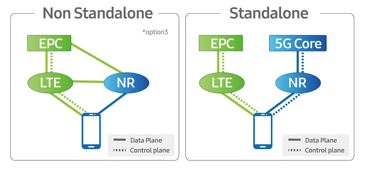
Some Arcane Detail: 5G Non-Standalone (NSA) vs Standalone (SA)
5G NSA (Non Standalone) uses LTE (4G) with an additional layer “bolted on” that uses 5G on the radio interface to provide “5G” speeds to users, while reusing the existing LTE (Evolved Packet Core) core and VoLTE for voice / SMS.
From an operator perspective there is almost no change required in the network to support NSA 5G, other than in the RAN, and almost all the 5G networks in commercial use today use 5G NSA.
5G NSA is great, it gives the user 5G speeds for users with phones that support it, with no change to the rest of the network needed.
Standalone 5G on the other hand requires an a completely new core network with all the trimmings.
While it is possible to handover / interwork with LTE/4G (Inter-RAT Handovers), this is like 3G/4G interworking, where each has a different core network. Introducing 5G standalone touches every element of the network, you need new nodes supporting the new standards for charging, policy, user plane, IMS, etc.
Scope
There’s an old adage that businesses spend money for one of three reasons:
To Save Money (Which we’ll cover in this post)
To make more Money (Covered next – Will link when published)
Because they have to (Regulatory compliance, insurance, taxes, etc)
Let’s look at 5G Standalone in each of these contexts:
5G Cost Savings – Counterpoint: The cost-benefit doesn’t stack up
As an operator with an existing deployed 4G LTE network, deploying a new 5G standalone network will not save you money.
From an capital perspective this is pretty obvious, you’re going to need to invest in a new RAN and a new core to support this, but what about from an opex perspective?
Claim: 5G RAN is more efficient than 4G (LTE) RAN
Spectrum is both finite and expensive, so MNOs must find the most efficient way to use that spectrum, to squeeze the most possible value out of it.
In rough numbers, we can say we get 5x the spectral efficiency by moving from 3G to 4G. This means we can carry 5.2x more with the same spectrum on 4G than we can on 3G – A very compelling reason to upgrade.
The like-for-like spectral efficiency of 5G is not significantly greater than that of LTE.
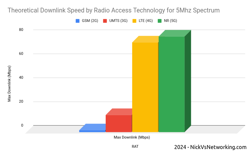
In numbers the same 5Mhz of spectrum we refarmed from UMTS (3G) to 4G (LTE) provided a 5x gain in efficiency to deliver 75Mbps on LTE. The same configuration refarmed to 5G-NR would provide 80Mbps.
Refarming spectrum from 4G (LTE) to 5G (NR) only provides a 6% increase in spectral efficiency.
While 6% is not nothing, if refarmed to a 5G standalone network, the spectrum can no longer be used by LTE only devices (Unless Dynamic Spectrum Sharing is used which in itself leads to efficiency losses), which in itself reduces the efficiency and would add additional load to other layers.
The crazy speeds demonstrated by 5G are not due to meaningful increases in efficiency, but rather the ability to use more spectrum, spectrum that operators need to purchase at auction, purchase equipment to utilize and pay to run.
Claim: 5G Standalone Core is Cheaper to operate as it is “Cloud Native”
It has been widely claimed that the shift for the 5G Core Architecture to being “Cloud Native” can provide cost savings.
Operators should regard this in a skeptical manner; after all, we’ve been here before.
Did moving from big-iron to VNFs provide the promised cost savings to operators?
For many operators the shift from hardware to software added additional complexity to the network and increased the headcount to support this.
What were once big-iron appliances dedicated to one job, that sat in the corner and chugged away, are now virtual machines (VNFs). Many operators have naturally found themselves needing a larger team to manage the virtual environment, compared to the size of the team they needed to just to plug power and data into a big box in an exchange before everything was virtualized.
Introducing a “Cloud Native” Kubernetes layer on top of the VNF / virtualization layer, on top of the compute layer, leaves us with a whole lot of layers. All of which require resources to be maintain, troubleshoot and kept running; each layer having associated costs for staffing, licensing and support.
Many mid size enterprises rushed into “the cloud” for the promised cost savings only to sheepishly admit it cost more than the expected.
Almost none of the operators are talking about running these workloads in the public cloud, but rather “Private Clouds” built on-premises, using “Cloud Native” best practices.
One of the central arguments about cloud revolves around “elastic scaling” where the network can automatically scale to match demand; think extra instances spun up a times of peak demand and shut down when the demand drops.
I explain elastic scaling to clients as having to move people from one place to another. Most of the time, I’m just moving myself, a push bike is fine, or I’ve got a 4 seater car, but occasionally I’ll need to move 25 people and for that I’d need a bus.
If I provide the transportation myself, I need to own a bike, a car and a bus.
But if use the cloud I can start with the push bike, and as I need to move more people, the “cloud” will provide me the vehicle I need to move the people I need to move at that moment, and I’ll just pay for the time I need the bus, and when I’m done needing the bus, I drop back to the (cheaper) push bike when I’m not moving lots of people.
While telecom operators are going to provide the servers to run this in “On-prem-cloud”, they need to dimension for the maximum possible load. This means they need to own a bike/car/bus, even if they’re not using it most of the time, and there’s really no cost savings to having a bus but not using it when you’re not paying by the hour to hire it.
Infrastructure aside, introducing a Standalone 5G Core adds another core network to maintain. Alongside the Circuit Switched Core (MSC/GGSN/SGSN) serving 2G/3G subscribers, Evolved Packet Core serving 4G (LTE) and 5G-NSA subscribers, adding a 5G Standalone Core to for the 5G-SA subscribers served by the 5G SA cells, is going to be more work (and therefore cost).
While the majority of operators have yet to turn off their 2G/3G core networks, introducing another core network to run in parallel is unlikely to lead to any cost savings.
Claim: Upgrading now can save money in the Future / Future Proofing
Life cycles of telecommunications are two fold, one is the equipment/platform life cycle (like the RAN components or Core network software being used to deliver the service) the other is the technology life cycle (the generation of technology being used).
The technology lifecycles in telecommunications are vastly longer than that for regular tech.
GSM (2G) was introduced into the UK in 1991, and will be phased out starting in 2033, a 42 year long technology life cycle.
No vendor today could reasonably expect the 5G hardware you deploy in 2024 to still be in production in 2066 – The platform/equipment life cycle is a lot shorter than the technology life cycle.
Operators will to continue relying on LTE (4G) well into the late 2030s.
I’d wager that there is not a single piece of equipment in the Vodafone UK GSM network today, that was there in 1991. I’d go even further to say that any piece of equipment in the network today, didn’t even replace the 1991 equipment, but was probably 3 or 4 generations removed from the network built in 1991.
For most operators, RAN replacements happen between 4 to 7 years, often with targeted augmentation / expansion as needed in the form of adding extra layers / sectors between these times.
The question operators should be asking is therefore not what will I need to get me through to 2066, but rather what will I need to get to 2030?
The majority of operators outside the US today still operate a 2G or 3G network, generally with minimal bandwidth to support legacy handsets and devices, while the 4G (LTE) network does most of the heavy lifting for carrying user traffic. This is often with the aid of an additional 5G-NSA (Non-Standalone) layer to provide additional capacity.
Is there a cost saving angle to adding support for 5G-Standalone in addition to 2G/3G/4G (LTE) and 5G (Non-Standalone) into your RAN?
A logical stance would be that removing layers / technologies (such as 2G/3G sunsetting) would lead to cost savings, and adding a 5G Standalone layer would increase cost.
All of the RAN solutions on the market today from the major vendors include support for both Standalone 5G and Non Standalone, but the feature licensing for a non-standalone 5G is generally cheaper than that for Standalone 5G.
The question operators should be asking is on what timescale do I need Standalone 5G?
If you’ve rolled out 5G-NSA today, then when are you looking to sunset your LTE network? If the answer is “I hope to have long since retired by that time”, then you’ve just answered that question and you don’t need to licence / deploy 5G-SA in this hardware refresh cycle.
Other Cost Factors
Roaming: The majority of roaming traffic today relies on 2G/3G for voice. VoLTE roaming is (finally) starting to establish a foothold, but we are a long way from ubiquitous global roaming for LTE and VoLTE, and even further away for 5G-SA roaming. Focusing on 5G roaming will enable your network for roaming use by a miniscule number of operators, compared to LTE/VoLTE roaming which covers the majority of the operators in the developed world who can utilize your service.
I decided to split this into 3 posts, next I’ll post the “5G can make us more money” post and finally a “5G because we have to” post. I’ll post that on LinkedIn / Twitter / Mailing list, so stick around, and feel free to trash me in the comments.
Slicing has long been held up as one of the monetizations opportunities for residential customers, but few seem to be familiar with it beyond a concept, so I thought I’d take a look at how it actually works in Android, and how an end user would interact with it.
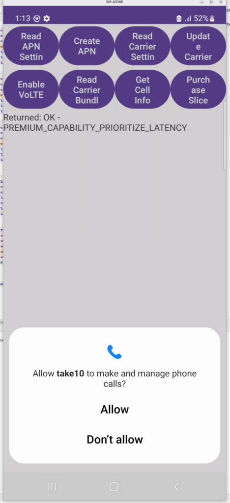
For starters, there’s a little used hook in Android TelephonyManager called purchasePremiumCapability, this method can be called by a carrier’s self care app.
Operators would need the Telephony Permission for their app, and a function from the app in order to activate this, but it doesn’t require on Android Carrier Privileges and a matching signature on the SIM card, although there’s a lot of good reasons to include this in your Android Manifest for a Carrier Self-Care app.
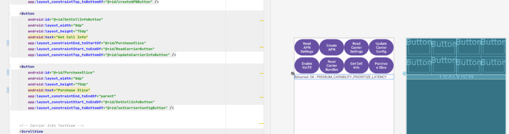
We’ve made a little test app we use for things like enabling VoLTE, setting the APNs, setting carrier config, etc, etc. I added the Purchase Slice capability to it and give it a shot.
And the hook works, I was able to “purchase” a Slice.
I did some sleuthing to find if any self-care apps from carriers have implemented this functionality for standards-based slicing, and I couldn’t find any, I’m curious to see if it takes off – as I’ve written about previously slicing capabilities are not new in cellular, but the attempt to monetise it is.
Even before 5G was released, the arms race to claim the “fastest” speeds on LTE, NSA and SA networks has continued, with pretty much every operator claiming a “first” or “fastest”.
I myself have the fastest 5G network available* but I thought I’d look at how big the values are we can put in for speed, these are the Maximum Bitrate Values (like AMBR) we can set on an APN/DNN, or on a Charging Rule.
*Measurement is of the fastest 5G network in an eastward facing office, operated by a person named Nick, in a town in Australia. Other networks operated by people other than those named Nick in eastward facing office outside of Australia were not compared.
The answer for Release 8 LTE is 4294967294 bytes per second, aka 4295 Mbps 4.295 Gbps.
Not bad, but why this number?
The Max-Requested-Bandwidth-DL AVP tells the PGW the max throughput allowed in bits per second. It’s a Unsigned32 so max value is 4294967294, hence the value.
But come release 15 some bright spark thought we may in the not to distant future break this barrier, so how do we go above this?
The answer was to bolt on another AVP – the “Extended-Max-Requested-BW-DL” AVP ( 554 ) was introduced, you might think that means the max speed now becomes 2x 4.295 Gbps but that’s not quite right – The units was shifted.
This AVP isn’t measuring bits per second it’s measuring kilobits per second.
So the standard Max-Requested-Bandwidth-DL AVP gives us 4.3 Gbps, while the Extended-Max-Requested-Bandwidth gives us a 4,295 Gbps.
We add the Extended-Max-Requested-Bandwidth AVP (4295 Gbps) onto the Max-Requested Bandwidth AVP (4.3 Gbps) giving us a total of 4,4299.3 Gbps.
The Binding Support Function is used in 4G and 5G networks to allow applications to authenticate against the network, it’s what we use to authenticate for XCAP and for an Entitlement Server.
Rather irritatingly, there are two BSF addresses in use:
If the ISIM is used for bootstrapping the FQDN to use is:
bsf.ims.mncXXX.mccYYY.pub.3gppnetwork.org
But if the USIM is used for bootstrapping the FQDN is
bsf.mncXXX.mccYYY.pub.3gppnetwork.org
You can override this by setting the 6FDA EF_GBANL (GBA NAF List) on the USIM or equivalent on the ISIM, however not all devices honour this from my testing.
For the past few months I’ve had a Band 78 NR active antenna unit sitting next to my desk.
It’s a very cool bit of kit that doesn’t get enough love, but I thought I’d pop open the radome and take a peek inside.
Individual antenna elements
What I found very interesting is that it’s not all antennas in there!
… 29, 30, 31, 32. Yup. Checks out.
There are the expected number of antennas (I mean if I opened it up and found 31 antennas I’d have been surprised) but they don’t take up the whole volume of the unit, only about half,
AAU with Radome reinstalled
Well, after that strip show, back to sitting in my office until I need to test something 5G SA again…