One of the new features of 5GC is the introduction of Service Based Interfaces (SBI) which is part of 5GC’s Service Based Architecture (SBA).
Let’s start with the description from the specs:
3GPP TS 23.501 [3] defines the 5G System Architecture as a Service Based Architecture, i.e. a system architecture in which the system functionality is achieved by a set of NFs providing services to other authorized NFs to access their services.
3GPP TS 29.500 – 4.1 NF Services
For that we have two key concepts, service discovery, and service consumption
Services Consumer / Producers
That’s some nice words, but let’s break down what this actually means, for starters, let’s talk about services.
In previous generations of core network we had interfaces instead of services. Interfaces were the reference point between two network elements, describing how the two would talk. The interfaces were the protocols the two interfaces used to communicate.
For example, in EPC / LTE S6a is the interface between the MME and the HSS, S5 is the interface between the S-GW and P-GW. You could lookup the 3GPP spec for each interface to understand exactly how it works, or decode it in Wireshark to see it in action.
5GC moves from interfaces to services. Interfaces are strictly between two network elements, the S6a interface is only used between the MME and the HSS, while a service is designed to be reusable.
This means the Service Based Interface N5g-eir can be used by the AMF, but it could equally be used by anyone else who wants access to that information.
3GPP defines the service in the form of service producer (The EIR produces the N5g-eir service) and the service consumer (The client connecting to the N5g-eir service), but doens’t restrict which network elements can
This gets away from the soup of interfaces available, and instead just defines the services being offered, rather than locking the
“service consumers” (which can be thought of clients in a client/server model) can discover “service producers” (like servers in a client/server model).
Our AMF, which acts as a “service consumer” consuming services from the UDM/UDR and SMF.
Service Discovery – Automated Discovery of NF Services
Service-Based Architecture enables 5G Core Network Function service discovery.
In simple terms, this means rather that your MME being told about your SGW, the nodes all talk to a “Network Repository Function” that returns a list of available nodes.
This post follows on from Part 1 and Part 2 of this 3 part series.
We are forced to move to 5G-SA
Claim: We must use 5G-SA with this spectrum (It’s a condition of the license)
I’ll concede that if it is a requirement for a license or funding, that 5G-SA be used, then that’s a pretty ironclad reason to introduce 5G-SA.
Claim: Users will Leave if you don’t have 5G-SA
We could argue the opposite effect will happen; Shifting to SA will reduce your user base. Here’s why:
Users experiencing 5G-NSA (Non-Standalone) today, are already getting the speed boost from “5G”.
From a user perspective, while 5G-NSA support has been becoming common on mid-to-high priced handsets, handsets supporting 5G-SA are far less common.
Dish’ Project Genesis is one of the only examples of a 5G SA network deployed on a large scale. It launched with only a single supported phone (A Motorola branded handset) and today the supported phone list is very short, limited to expensive flagships. This lack of handset support means users must purchase a handset through Dish rather than being able to bring their own phones, as the only way that compatibility can be guaranteed is by controlling the whole ecosystem.
Unless you are in a highly developed market with 2G and 3G turned off, where the majority of your user base has recent generation flagship phones capable of supporting these features, you’re shrinking your addressable market with 5G-SA, rather than expanding it.
Conclusion – 5G-SA doesn’t stack up, what do I do?
SA doesn’t make sense for a lot of operators and markets – for now. I’m sure this post will look pretty dated in a few years time as many of these factors change and as operators sunset 2G and 3G networks.
I’m not advocating for 5G-SA never, I’m advocating not 5G-SA today.
There are simply better options out there for spending that operations budget to make network improvements.
Off the bat some ideas to expore:
Optimize your existing network.
Roll out NSA to an even larger area.
Shutdown 2G/3G layers.
Simplify your operations.
Cut down the number of vendors and moving parts.
Simplify again.
Automate.
Simplify more.
Doing this will mean you can enjoy cost savings from reduced headcount thanks to a simpler network. Simpler networks have better up-time, thanks to operating a network that’s less frankensteiny – less cobbled together from disparate legacy parts. You’ll also Enjoy reduced opex from all the systems you’ve shut down and cheaper roaming from all the bilaterals you moved to VoLTE.
All of these tasks will keep project teams busy for years and put the MNO in a stronger position moving forward, without getting distracted by slick marketing and shiny brochures.
To make more Money (This post, congratulations, you’re reading it!)
Because they have to (Regulatory compliance, insurance, taxes, etc) – That’s the next post
So let’s look at SA in this context.
5G-SA can drive new revenue streams
We (as an industry) suck at this.
Last year on the Telecoms.com podcast, Scott Bicheno made the point that if operators took all the money they’d gambled (and lost) on trying to play in the sports rights, involvement in media companies, building their own streaming apps, attempts at bundling other utilities, digital identity, etc, and just left the cash in the bank and just operated the network, they’d be better off.
Uber, Spotify, “OTTs”, etc, utilize MNOs to enable their services, but operators don’t see this extra revenue. While some operators may talk of “fair share” the truth is, these companies add value to our product (connectivity) which as an industry, we’ve failed to add ourselves.
If the Metaverse does turn out to be a cash cow, it is unlikely the telecommunications industry will be the ones milking it.
Claim: Customers are willing to pay more for 5G-SA
This myth seems to be fairly persistent, but with minimal data to support this claim.
While BSS vendors talk about “5G Monetization”, the truth is, people use their MNO to provide them connectivity. If the coverage is adequate, and the speed enough to do what they need to do, few would be willing to pay any additional cash each month to see higher numbers on a speedtest result (enabled by 5G-NSA) and even fewer would pay extra cash for, well, whatever those features only enabled by 5G-Standalone are?
With most consumers now also holding onto their mobile devices for longer periods of time, and with interest rates reining in consumer spending across the board, we are seeing the rise of a more cost conscious consumer than ever before. If we want to see higher ARPUs, we need to give the consumer a compelling reason to care and spend their cash, beyond a speed test result.
We talk a little about APIs lower down in the post.
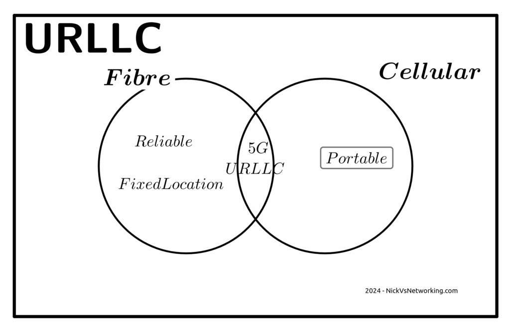
Claim: Users want Ultra-Low Latency / High Reliability Comms that only 5G-SA delivers
Wanting to offer a product to the market, is not the same as the market wanting a product to consume.
Telecom operators want customers to want these services, but customer take up rates tell a different story. For a product like this to be viable, it must have a wide enough addressable market to justify the investment.
Reliability
The URLCC standards focus on preventing packet loss, but the world has moved on from needing zero packet loss.
The telecom industry has a habit of deciding what customers want without actually listening. When a customer talks about wanting “reliable” comms, they aren’t saying they want zero packet loss, but rather fewer dropouts or service flaps. For us to give the customer what they are actually asking for involves us expanding RAN footprint and adding transmission diversity, not 5G-SA.
The “protocols of the internet” (TCP/IP) have been around for more than 50 years now.
These protocols have always flowed over transport links with varied reliability and levels of packet loss.
Thanks to these error correction and retransmission techniques built into these protocols, a lost packet will not interrupt the stream. If your nuclear command and control network were carried over TCP/IP over the public internet (please don’t do this), a missing packet won’t lead to worldwide annihilation, but rather the sender will see the receiver never acknowledged the receipt of the packet at the other end, and resend it, end of.
If you walk into a hospital today, you’ll find patient monitoring devices, tracking the vital signs for patients and alerting hospital staff if a patient’s vital signs change. It is hard to think of more important services for reliability than this.
And yet they use WiFi, and have done for a long time, if a packet is lost on WiFi (as happens regularly) it’s just retransmitted and the end user never knows.
Autonomous cars are unlikely to ever rely on a 5G connection to operate, for the simple reason that coverage will never be 100%. If your car stops because you’re in a not-spot, you won’t be a happy customer. While plenty of cars have cellular modems in them, that are used to upload telemetry data back to the manufacturer, but not to drive the car.
One example of wireless controlled vehicles in the wild is autonomous haul trucks in mines. Historically, these have used WiFi for their comms. Mine sites are often a good fit for Private LTE, but there’s nothing inherent in the 5G Standalone standard that means it’s the only tool for the job here.
Slicing
Slicing is available in LTE (4G), with an architecture designed to allow access to others. It failed to gain traction, but is in networks today.
The RAN a piece of the latency puzzle here, but it is just one piece of the puzzle.
If we look at the flow a packet takes from the user’s device to the server they want to talk to we’ve got:
Time it takes the UE to craft the packet
Time it takes for the packet to be transmitted over the air to the base station
Time it takes for the packet to get through the RAN transmission network to the core
Time it takes the packet to traverse the packet core
Time it takes for the packet to get out to transit/peering
Time it takes to get the packet from the edge of the operators network to the edge of the network hosting the server
Time it takes the packet through the network the server is on
Time it takes the server to process the request
The “low latency” bit of the 5G puzzle only involves the two elements in bold.
If you’ve got to get from point A to point B along a series of roads, and the speed limit on two of the roads you traverse (short sections already) is increased. The overall travel time is not drastically reduced.
I’m lucky, I have access to a well kitted out lab which allows me to put all of these latency figures to the test and provide side by side metrics. If this is of interest to anyone, let me know. Otherwise in the meantime you’ll just have to accept some conjecture and opinion.
You could rebut this talking about Edge Compute, and having the datacenter at the base of the tower, but for a number of fairly well documented reasons, I think this is unlikely to attract widespread deployment in established carrier networks, and Intel’s recent yearly earning specifically called this out.
Claim: Customers want APIs and these needs 5G SA
Companies like Twilio have made it easy to interact with the carrier network via their APIs, but yet again, it’s these companies producing the additional value on a service operated by the MNOs.
My coffee machine does not have an API, and I’m OK with this because I don’t have a want or need to interact with it programatically.
By far, the most common APIs used by businesses involving telco markets are APIs to enable sending an SMS to a user.
These have been around for a long time, and the A2P market is pretty well established, and the good news is, operators already get a chunk of this pie, by charging for the SMS.
Imagine a company that makes medical booking software. They’re a tech company, so they want their stack to work anywhere in the world, and they want to be able to send reminder SMS to end users.
They could get an account manager with each of the telcos in each of the markets they work in, onboard and integrate the arcane complexities of each operators wholesale SMS system, or they could use Twilio or a similar service, which gives them global reach.
Often the cost of services like Twilio are cheaper than working directly with the carriers in each market, and even if it is marginally more expensive, the cost savings by not having to deal with dozens of carriers or integrate into dozens of systems, far outweighs this.
While it’s a great idea, in the context of 5G Standalone and APIs, it’s worth noting that none of the use cases in OpenGateway require 5G Standalone (Except possibly Edge discovery, but it is debatable).
Critically, from a developer experience perspective:
I can sign up to services like Twilio without a credit card, and start using the service right away, with examples in my programming language of choice, the developer user experience is fantastic.
Jump on the OpenGateway website today and see if you can even find a way to sign up to use the service?
Claim: Fixed Wireless works best with 5G-SA
Of all the touted use cases and applications for 5G, Fixed Wireless (FWA) has been the most successful.
The great thing about FWA on Cellular networks is you can use the same infrastructure you use for your mobile customers, and then sell excess capacity in the network to deliver Fixed Wireless Access services, better utilizing an asset (great!).
But again, this does not require Standalone 5G. If you deploy your FWA network using 5G SA, then you won’t be able to sweat that same asset for both mobile subscribers and FWA subscribers.
Today at least, very few handsets short of this generation of flagship phones, supports 5G SA. Even the phones sold as supporting 5G over the past few years, are almost all only supporting 5G-NSA, so if you rolled out your FWA network as Standalone, you can’t better utilize the asset by sharing with your existing LTE/5G-NSA customers.
Claim: The Killer App is coming for 5G and it needs 5G SA
This space is reserved for the killer app that requires 5G Standalone.
Whenever that comes?
Anyone?
I’m not paying to build a marina berth for my mega yacht, mostly because I don’t have one. Ditto this.
Could you explain to everyone on an investor call that you’re investing in something where the vessel of the payoff isn’t even known to exist? Telecom is “blue chip”, hardly speculative.
The Future for Revenue Growth?
Maybe there isn’t one.
I know it’s an unthinkable thought for a lot of operators, but let’s look at it rationally; in the developed world, everyone who wants a mobile service already has one.
This leaves operators with two options; gaining market share from their competitors and selling more/higher priced services to existing customers.
You don’t steal away customers from other operators by offering a higher priced product, and with reduced consumer spending people aren’t queuing up to spend more each month.
But there is a silver lining, if you can’t grow revenues, you can still shrink expenditure, which in the end still gets the same result at the end of the quarter – More cash.
Simplify your operations, focus on what you do really well (mobile services), the whole 80/20 rule, get better at self service, all that guff.
There’s no shortage of pain points for consumers telecom operators could address, to make the customer experience better, but few that include the word Slicing.
No one spends marketing dollars talking about the problems with a tech and vendors aren’t out there promoting sweating existing assets. But understanding your options as an operator is more important now than ever before.
Sidebar; This post got really long, so I’m splitting it into 3…
We’re often asked to help define a a 5G strategy for operators; while every case is different, there’s a lot of vendors pushing MNOs to move towards 5G standalone or 5G-SA.
I’m always a fan of playing “devil’s advocate“, and with so many articles and press releases singing the praises of standalone 5G/5G-SA, so as a counter in this post, I’ll be making the case against the narratives presented to operators by vendors that the “right” way to do 5G is to introduce 5G Standalone, that they should all be “upgrading” to Standalone 5G.
With Mobile World Congress around the corner, now seems like a good time to put forward the argument against introducing 5G Standalone, rebutting some common claims about 5G Standalone operators will be told. We’ll counterpoint these arguments and I’ll put forward the case for not jumping onto the 5G-SA bandwagon – just yet.
On a personal note, I do like 5G SA, it has some real advantages and some cool features, which are well documented, including on this blog. I’m not looking to beat up on any vendors, marketing hype or events, but just to provide the “other side” of the equation that operators should consider when making decisions and may not be aware of otherwise. It’s also all opinion of course (cited where possible), but if you’re going to build your network based on a blog post (even one as good as this) you should probably reconsider your life choices.
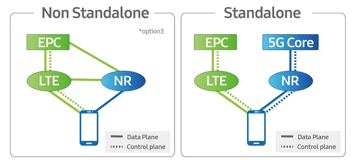
Some Arcane Detail: 5G Non-Standalone (NSA) vs Standalone (SA)
5G NSA (Non Standalone) uses LTE (4G) with an additional layer “bolted on” that uses 5G on the radio interface to provide “5G” speeds to users, while reusing the existing LTE (Evolved Packet Core) core and VoLTE for voice / SMS.
From an operator perspective there is almost no change required in the network to support NSA 5G, other than in the RAN, and almost all the 5G networks in commercial use today use 5G NSA.
5G NSA is great, it gives the user 5G speeds for users with phones that support it, with no change to the rest of the network needed.
Standalone 5G on the other hand requires an a completely new core network with all the trimmings.
While it is possible to handover / interwork with LTE/4G (Inter-RAT Handovers), this is like 3G/4G interworking, where each has a different core network. Introducing 5G standalone touches every element of the network, you need new nodes supporting the new standards for charging, policy, user plane, IMS, etc.
Scope
There’s an old adage that businesses spend money for one of three reasons:
To Save Money (Which we’ll cover in this post)
To make more Money (Covered next – Will link when published)
Because they have to (Regulatory compliance, insurance, taxes, etc)
Let’s look at 5G Standalone in each of these contexts:
5G Cost Savings – Counterpoint: The cost-benefit doesn’t stack up
As an operator with an existing deployed 4G LTE network, deploying a new 5G standalone network will not save you money.
From an capital perspective this is pretty obvious, you’re going to need to invest in a new RAN and a new core to support this, but what about from an opex perspective?
Claim: 5G RAN is more efficient than 4G (LTE) RAN
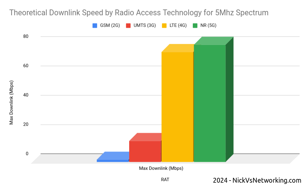
Spectrum is both finite and expensive, so MNOs must find the most efficient way to use that spectrum, to squeeze the most possible value out of it.
In rough numbers, we can say we get 5x the spectral efficiency by moving from 3G to 4G. This means we can carry 5.2x more with the same spectrum on 4G than we can on 3G – A very compelling reason to upgrade.
The like-for-like spectral efficiency of 5G is not significantly greater than that of LTE.
In numbers the same 5Mhz of spectrum we refarmed from UMTS (3G) to 4G (LTE) provided a 5x gain in efficiency to deliver 75Mbps on LTE. The same configuration refarmed to 5G-NR would provide 80Mbps.
Refarming spectrum from 4G (LTE) to 5G (NR) only provides a 6% increase in spectral efficiency.
While 6% is not nothing, if refarmed to a 5G standalone network, the spectrum can no longer be used by LTE only devices (Unless Dynamic Spectrum Sharing is used which in itself leads to efficiency losses), which in itself reduces the efficiency and would add additional load to other layers.
The crazy speeds demonstrated by 5G are not due to meaningful increases in efficiency, but rather the ability to use more spectrum, spectrum that operators need to purchase at auction, purchase equipment to utilize and pay to run.
Claim: 5G Standalone Core is Cheaper to operate as it is “Cloud Native”
It has been widely claimed that the shift for the 5G Core Architecture to being “Cloud Native” can provide cost savings.
Operators should regard this in a skeptical manner; after all, we’ve been here before.
Did moving from big-iron to VNFs provide the promised cost savings to operators?
For many operators the shift from hardware to software added additional complexity to the network and increased the headcount to support this.
What were once big-iron appliances dedicated to one job, that sat in the corner and chugged away, are now virtual machines (VNFs). Many operators have naturally found themselves needing a larger team to manage the virtual environment, compared to the size of the team they needed to just to plug power and data into a big box in an exchange before everything was virtualized.
Introducing a “Cloud Native” Kubernetes layer on top of the VNF / virtualization layer, on top of the compute layer, leaves us with a whole lot of layers. All of which require resources to be maintain, troubleshoot and kept running; each layer having associated costs for staffing, licensing and support.
Many mid size enterprises rushed into “the cloud” for the promised cost savings only to sheepishly admit it cost more than the expected.
Almost none of the operators are talking about running these workloads in the public cloud, but rather “Private Clouds” built on-premises, using “Cloud Native” best practices.
One of the central arguments about cloud revolves around “elastic scaling” where the network can automatically scale to match demand; think extra instances spun up a times of peak demand and shut down when the demand drops.
I explain elastic scaling to clients as having to move people from one place to another. Most of the time, I’m just moving myself, a push bike is fine, or I’ve got a 4 seater car, but occasionally I’ll need to move 25 people and for that I’d need a bus.
If I provide the transportation myself, I need to own a bike, a car and a bus.
But if use the cloud I can start with the push bike, and as I need to move more people, the “cloud” will provide me the vehicle I need to move the people I need to move at that moment, and I’ll just pay for the time I need the bus, and when I’m done needing the bus, I drop back to the (cheaper) push bike when I’m not moving lots of people.
While telecom operators are going to provide the servers to run this in “On-prem-cloud”, they need to dimension for the maximum possible load. This means they need to own a bike/car/bus, even if they’re not using it most of the time, and there’s really no cost savings to having a bus but not using it when you’re not paying by the hour to hire it.
Infrastructure aside, introducing a Standalone 5G Core adds another core network to maintain. Alongside the Circuit Switched Core (MSC/GGSN/SGSN) serving 2G/3G subscribers, Evolved Packet Core serving 4G (LTE) and 5G-NSA subscribers, adding a 5G Standalone Core to for the 5G-SA subscribers served by the 5G SA cells, is going to be more work (and therefore cost).
While the majority of operators have yet to turn off their 2G/3G core networks, introducing another core network to run in parallel is unlikely to lead to any cost savings.
Claim: Upgrading now can save money in the Future / Future Proofing
Life cycles of telecommunications are two fold, one is the equipment/platform life cycle (like the RAN components or Core network software being used to deliver the service) the other is the technology life cycle (the generation of technology being used).
The technology lifecycles in telecommunications are vastly longer than that for regular tech.
GSM (2G) was introduced into the UK in 1991, and will be phased out starting in 2033, a 42 year long technology life cycle.
No vendor today could reasonably expect the 5G hardware you deploy in 2024 to still be in production in 2066 – The platform/equipment life cycle is a lot shorter than the technology life cycle.
Operators will to continue relying on LTE (4G) well into the late 2030s.
I’d wager that there is not a single piece of equipment in the Vodafone UK GSM network today, that was there in 1991. I’d go even further to say that any piece of equipment in the network today, didn’t even replace the 1991 equipment, but was probably 3 or 4 generations removed from the network built in 1991.
For most operators, RAN replacements happen between 4 to 7 years, often with targeted augmentation / expansion as needed in the form of adding extra layers / sectors between these times.
The question operators should be asking is therefore not what will I need to get me through to 2066, but rather what will I need to get to 2030?
The majority of operators outside the US today still operate a 2G or 3G network, generally with minimal bandwidth to support legacy handsets and devices, while the 4G (LTE) network does most of the heavy lifting for carrying user traffic. This is often with the aid of an additional 5G-NSA (Non-Standalone) layer to provide additional capacity.
Is there a cost saving angle to adding support for 5G-Standalone in addition to 2G/3G/4G (LTE) and 5G (Non-Standalone) into your RAN?
A logical stance would be that removing layers / technologies (such as 2G/3G sunsetting) would lead to cost savings, and adding a 5G Standalone layer would increase cost.
All of the RAN solutions on the market today from the major vendors include support for both Standalone 5G and Non Standalone, but the feature licensing for a non-standalone 5G is generally cheaper than that for Standalone 5G.
The question operators should be asking is on what timescale do I need Standalone 5G?
If you’ve rolled out 5G-NSA today, then when are you looking to sunset your LTE network? If the answer is “I hope to have long since retired by that time”, then you’ve just answered that question and you don’t need to licence / deploy 5G-SA in this hardware refresh cycle.
Other Cost Factors
Roaming: The majority of roaming traffic today relies on 2G/3G for voice. VoLTE roaming is (finally) starting to establish a foothold, but we are a long way from ubiquitous global roaming for LTE and VoLTE, and even further away for 5G-SA roaming. Focusing on 5G roaming will enable your network for roaming use by a miniscule number of operators, compared to LTE/VoLTE roaming which covers the majority of the operators in the developed world who can utilize your service.
I decided to split this into 3 posts, next I’ll post the “5G can make us more money” post and finally a “5G because we have to” post. I’ll post that on LinkedIn / Twitter / Mailing list, so stick around, and feel free to trash me in the comments.
Today, we’re going to look at one of the simplest Service Based Interfaces in the 5G Core, the Equipment Identity Register (EIR).
The purpose of the EIR is very simple – When a subscriber connects to the network it’s Permanent Equipment Identifier (PEI) can be queried against an EIR to determine if that device should be allowed onto the network or not.
The PEI is the IMEI of a phone / device, with the idea being that stolen phones IMEIs are added to a forbidden list on the EIR, and prohibited from connecting to the network, making them useless, in turn making stolen phones harder to resell, deterring mobile phone theft.
In reality these forbidden-lists are typically either country specific or carrier specific, meaning if the phone is used in a different country, or in some cases a different carrier, the phone’s IMEI is not in the forbidden-list of the overseas operator and can be freely used.
The dialog goes something like this:
AMF: Hey EIR, can PEI 49-015420-323751-8 connect to the network?
EIR: (checks if 49-015420-323751-8 in forbidden list - It's not) Yes.
or
AMF: Hey EIR, can PEI 58-241992-991142-3 connect to the network?
EIR: (checks if 58-241992-991142-3 is in forbidden list - It is) No.
(Optionally the SUPI can be included in the query as well, to lock an IMSI to an IMEI, which is a requirement in some jurisdictions)
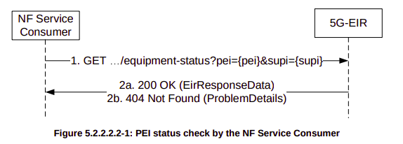
As we saw in the above script, the AMF queries the EIR using the N5g-eir_EquipmentIdentityCheck service.
The N5g-eir_EquipmentIdentityCheck service only offers one operation – CheckEquipmentIdentity.
It’s called by sending an HTTP GET to:
http://{apiRoot}/n5g-eir-eic/v1/equipment-status
Obviously we’ll need to include the PEI (IMEI) in the HTTP GET, which means if you remember back to basic HTTP GET, you may remember means you have to add ?attribute=value&attribute=value… for each attribute / value you want to share.
For the CheckEquipmentIdentity operation, the PEI is a mandatory parameter, and optionally the SUPI can be included, this means to query our PEI (The IMSI of the phone) against our EIR we’d simply send an HTTP GET to:
AMF: HTTP GET http://{apiRoot}/n5g-eir-eic/v1/equipment-status?pei=490154203237518
EIR: 200 (Body EirResponseData: status "WHITELISTED")
And how it would look for a blacklisted IMEI:
AMF: HTTP GET http://{apiRoot}/n5g-eir-eic/v1/equipment-status?pei=490154203237518
EIR: 404 (Body EirResponseData: status "BLACKLISTED")
Because it’s so simple, the N5g-eir_EquipmentIdentityCheck service is a great starting point for learning about 5G’s Service Based Interfaces.
Note: As this space develops so quickly I’ve refreshed the original post from November 2021 in March 2021 with updated instructions.
While 5G SA devices are still in their early stages, and 5G RAN hardware / gNodeBs are hard to come by, so today we’ll cover using UERANSIM to simulate UEs and 5G RAN, to put test calls through our 5GC.
Bringing your 5G Core Online
We’ll use Open5Gs for all the 5GC components, and install on any recent Ubuntu distribution.
The first point of contact we’ll need to talk about is the AMF,
The AMF – the Access and Mobility Function is reached by the gNodeB over the N2 interface. The AMF handles our 5G NAS messaging, which is the messaging used by the UEs / Devices to request data services, manage handovers between gNodeBs when moving around the network, and authenticate to the network.
By default the AMF binds to a loopback IP, which is fine if everything is running on the same box, but becomes an issue for real gNodeBs or if we’re running UERANSIM on a different machine.
This means we’ll need to configure our AMF to bind to the IP of the machine it’s running on, by configuring the AMF in /etc/open5gs/amf.yaml, so we’ll change the ngap addr to bind the AMF to the machine’s IP, for me this is 10.0.1.207,
ngap:
  - addr: 10.0.1.207
In the amf.conf there’s a number of things we can change and configure; such as the PLMN and network name, the NRF parameters, however for now we’ll keep it simple and leave everything else as default.
To allow the changes to take effect, we’ll restart the Open5GS AMF service to make our changes take effect;
$ sudo systemcl restart open5gs-amfd
Setting up the Simulator
We’re using UERANSIM as our UE & RAN Simulator, so we’ll need to get it installed. I’m doing this on an Ubuntu system as we’re using Snaps.
Once we’ve got the software installed we’ll need to put together the basic settings.
You should see these files in the /build/ directory and they should be executable.
Running the Simulator (UERANSIM)
UERANSIM has two key parts, like any RAN,
The first is the gNodeB, that connects to our AMF and handles subscriber traffic over our (simulated) radio link,
The other is our subscribers themselves – the UEs.
Both are defined and setup through config files in the config/ directory,
Configuring & Starting the gNodeB
While we’re not actually going to bring anything “on air” in the RF sense, we’ll still need to configure and start our gNodeB.
All the parameters for our gNodeB are set in the config/open5gs-gnb.yaml file,
Inside here we’ll need to set the the parameters of our simulated gNodeB, for us this means (unless you’ve changed the PLMN etc) just changing the Link IPs that the gNodeB binds to, and the IP of the AMFs (for me it’s 10.0.1.207) – you’ll need to substitute these IPs with your own of course.
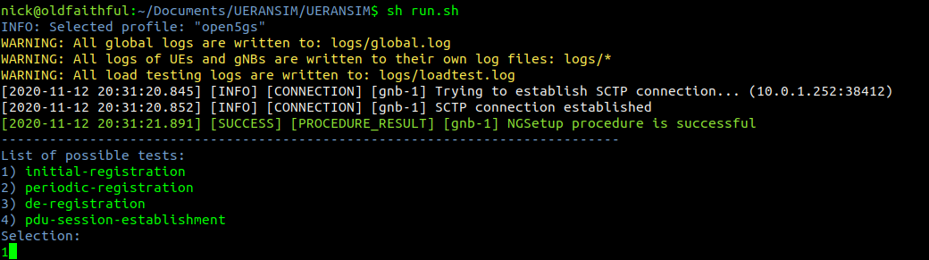
Now we should be able to start the gNodeB service and see the connection, let’s take a look,
We’ll start the gNodeB service from the UERANSIM directory by running the nr-gnb service with the config file we just configured in config/open5gs-gnb.yaml
$ build/nr-gnb -c config/open5gs-gnb.yaml
All going well you’ll see something like:
[2021-03-08 12:33:46.433] [ngap] [info] NG Setup procedure is successful
And if you’re running Wireshark you should see the NG-AP (N2) traffic as well;
If we tail the logs on the Open5GS AMF we should also see the connection too:
Configuring the UE Simulator
So with our gNodeB “On the air” next up we’ll connect a simulated UE to our simulated gNodeB.
We’ll leave the nr-gnb service running and open up a new terminal to start the UE with:
$ build/nr-gnb -c config/open5gs-gnb.yaml
But if you run it now, you’ll just see errors regarding the PLMN search failing,
So why is this? We need to tell our UE the IP of the gNodeB (In reality the UE would scan the bands to find a gNB to serve it, but we’re simulating hre).
So let’s correct this by updating the config file to point to the IP of our gNodeB, and trying again,
So better but not working, we see the RRC was released with error “FIVEG_SERVICES_NOT_ALLOWED”, so why is this?
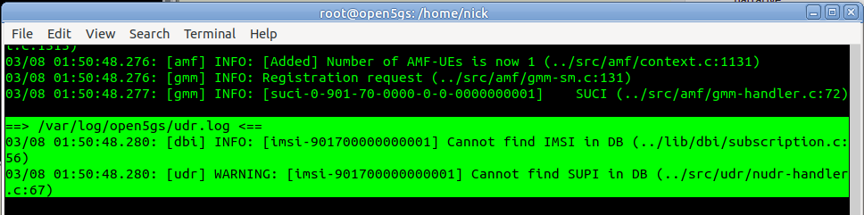
A quick look at the logs on Open5Gs provides the answer,
Of course, we haven’t configured the subscriber in Open5Gs’s UDM/UDR.
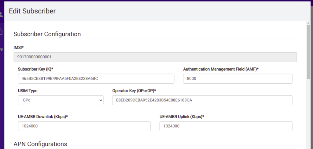
So we’ll browse to the web interface for Open5GS HSS/UDR and add a subscriber,
We’ll enter the IMSI, K key and OP key (make sure you’ve selected OPc and not OP), and save. You may notice the values match the defaults in the Open5GS Web UI, just without the spaces.
Running the UE Simulator
So now we’ve got all this configured we can run the UE simulator again, this time as Sudo, and we should get a very different ouput;
$ build/nr-gnb -c config/open5gs-gnb.yaml
Now when we run it we should see the session come up, and a new NIC is present on the machine, uesimtun0,
As the standardisation for 5G-SA has been completed and the first roll outs are happening, I thought I’d cover the basic architecture of the 5G Core Network, for people with a background in EPC/SAE networks for 4G/LTE, covering the key differences, what’s the same and what’s new.
The idea behind this, is that by removing the S-GW removes extra hops / latency in the network, and allows users to be connected to the best UPF for their needs, typically one located close to the user.
However, there are often scenarios where an intermediate function is required – for example wanting to anchor a session to keep an IP Address allocated to one UPF associated with a user, while they move around the network. In this scenario a UPF can act as an “Session Anchor” (Akin to a P-GW), and pass through “Intermediate UPFs” (Like S-GWs).
Unlike the EPCs architecture, there is no limit to how many I-UPFs can be chained together between the Session Anchoring UPF and the gNB, and this chaining of UPFs allows for some funky routing options.
The UPF is dumb by design. The primary purpose is just to encapsulate traffic destined from external networks to subscribers into GTP-U packets and forward them onto the gNodeB serving that subscriber, and the same in reverse. Do one thing and do it well.
SMF – Session Management Function
So with dumb UPFs we need something smarter to tell them what to do.
Control of the UPFs is handled by the SMF – Session Management Function, which signals using PFCP down to the UPFs to tell them what to do in terms of setting up connections.
This means the interface between the SMF and UPF (the N4 interface) is more or less the same as the interface between a P-GW-C and a P-GW-U seen in CUPS.
When a subscriber connects to the network and has been authenticated, the AMF (For more info on the AMF see the sister post to this topic covering Control Plane traffic) requests the SMF to setup a connection for the subscriber.
Interworking with EPC
For deployments with an EPC and 5GC interworking between the two is of course required.
The P-GW-C and P-GW-U communications using PFCP are essentially the same as the N4 interface (between the SMF and the UPF) so the P-GW-U is able to act as a UPF.
This means handovers between the two RATs / Cores is seamless as when moving from an LTE RAT and EPC to a 5G RAT and 5G Core, the same UPF/P-GW-U is used, and only the Control Plane signalling around it changes.
When moving from LTE to 5G RAT, the P-GW-C is replaced by the SMF, When moving from 5G RAT to LTE, the SMF is replaced by the P-GW-C. In both scenarios user plane traffic takes the same exit point to external Data Networks (SGi interface in EPC / N6 interface in 5GC).
Interfaces / Reference Points
N3 Interface
N3 interface connects the gNodeB user plane to the UPF, to transport GTP-U packets.
This is a User Plane interface, and only transports user plane traffic.
This is akin to the S1-UP interface in EPC.
N4 Interface
N4 interface connects the Session Management Function (SMF) control plane to the UPF, to setup, modify and delete UPF sessions.
It is a control plane interface, and does not transport User Plane traffic.
This interface relies on PFCP – Packet Forwarding Control Protocol.
This is akin to the SxB interface in EPC with CUPS.
N6 Interface
N6 interface connects the UPF to External Data Networks (DNs), taking packets destined for Subscribers and encapsulating them into GTP-U packets.
This is a User Plane interface, and only transports user plane traffic.
This is akin to the SGi interface in EPC.
N9 Interface
When Session Anchoring is used, and Intermediate-UPFs are used, the connection between these UPFs uses the N9 interface.
This is only used in certain scenarios – the preference is generally to avoid unnecessary hops, so Intermediate-UPF usage is to be avoided where possible.
As this is a User Plane interface, it only transports user plane traffic.
When used this would be akin to the S5 interface in EPC.
N11 Interface
SMFs need to be told when to setup / tear down connections, this information comes from the AMF via the N11 interface.
As this is a Control Plane interface, it only transports control plane traffic.
This is similar to the S11 interface between the MME and the S-GW in EPC, however it would be more like the S11 if the S11 terminated on the P-GW.
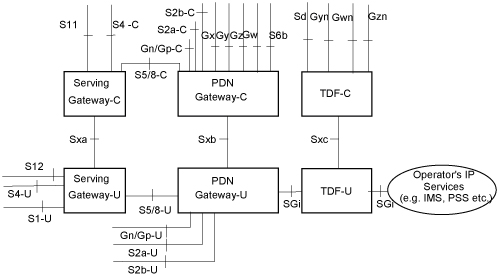
3GPP release 14 introduced the concept of CUPS – Control & User Plane Separation, and the Sx interface, this allows the control plane (GTP-C) functionality and the user plane (GTP-U) functionality to be separated, and run in a distributed fashion, allowing the node a user’s GTP-U traffic flows through to be in a different location to where the Control / Signalling traffic (GTP-C) flows.
In practice that means for an LTE EPC this means we split our P-GW and S-GW into a minimum of two network elements each.
A P-GW is split and becomes a P-GW-C that handles the P-GW Control Plane traffic (GTPv2-C) and a P-GW-U speaking GTP-U for our User Plane traffic. But the split doesn’t need to stop there, one P-GW-C could control multiple P-GW-Us, routing the user plane traffic. Sames goes for S-GW being split into S-GW-C and S-GW-U,
This would mean we could have a P-GW-U located closer to a eNB / User to reduce latency, by allowing GTP-U traffic to break out on a node closer to the user.
It also means we can scale better too, if we need to handle more data traffic, but not necessarily more control plane traffic, we can just add more P-GW-U nodes to handle this.
To manage this a new protocol was defined – PFCP – the Packet Forwarding Control Protocol. For LTE this is refereed to as the Sx reference point, it’ also reused in 5G-SA as the N4 reference point.
When a GTP-C “Create Session Request” comes into a P-GW for example from an S-GW, a PFCP “Session Establishment Request” is sent by the P-GW-C to the P-GW-U with much the same information that was in the GTP-C request, to setup the session.
So why split the Control and User Plane traffic if you’re going to just relay the GTP-C traffic in a different format?
That was my first question – the answer is that keeping the GTP-C interface ensures backward compatibility with older MMEs, PCRFs, charging systems, and allows a staged roll out and bolting on extra capacity.
GTP-C disappears entirely in 5G Standalone architecture and is replaced with the N4 interface, which uses PFCP for the Control Plan and GTP-U again.
Here’s a capture from Open5Gs core showing GTPv2C and PFCP in play.