I was recently in Sydney for a GSMA event with a few extra days in town to show one of our team members who was visiting from the US, around a city I don’t even live in.
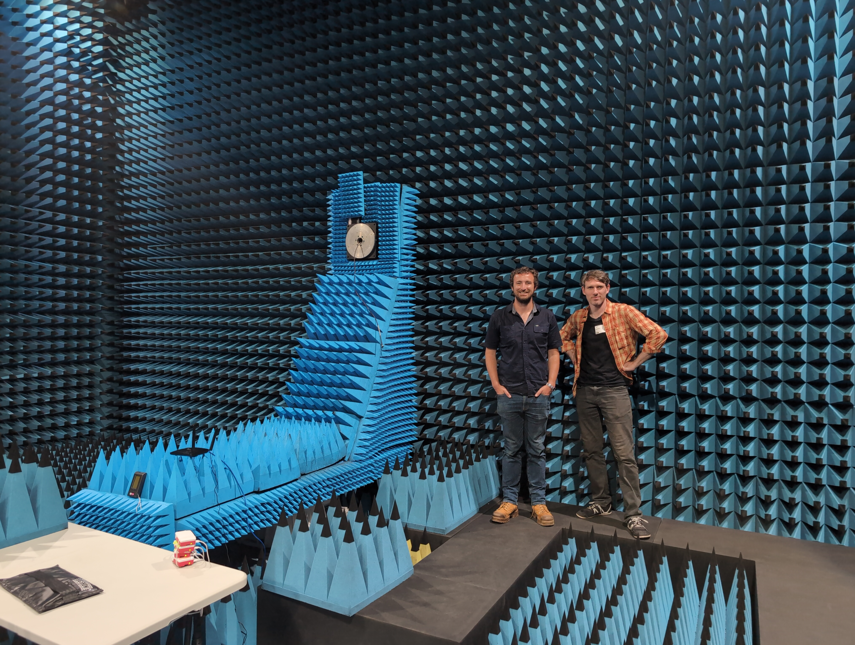
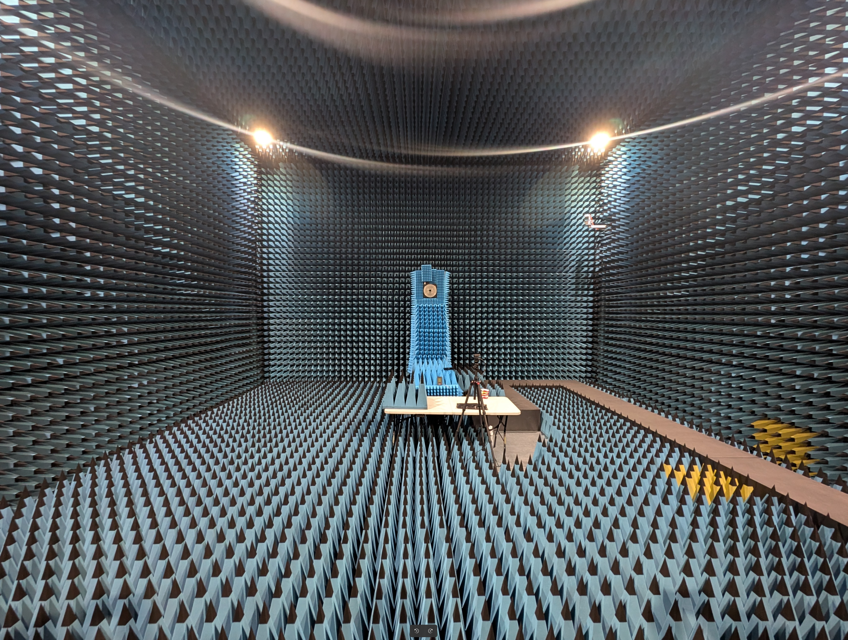
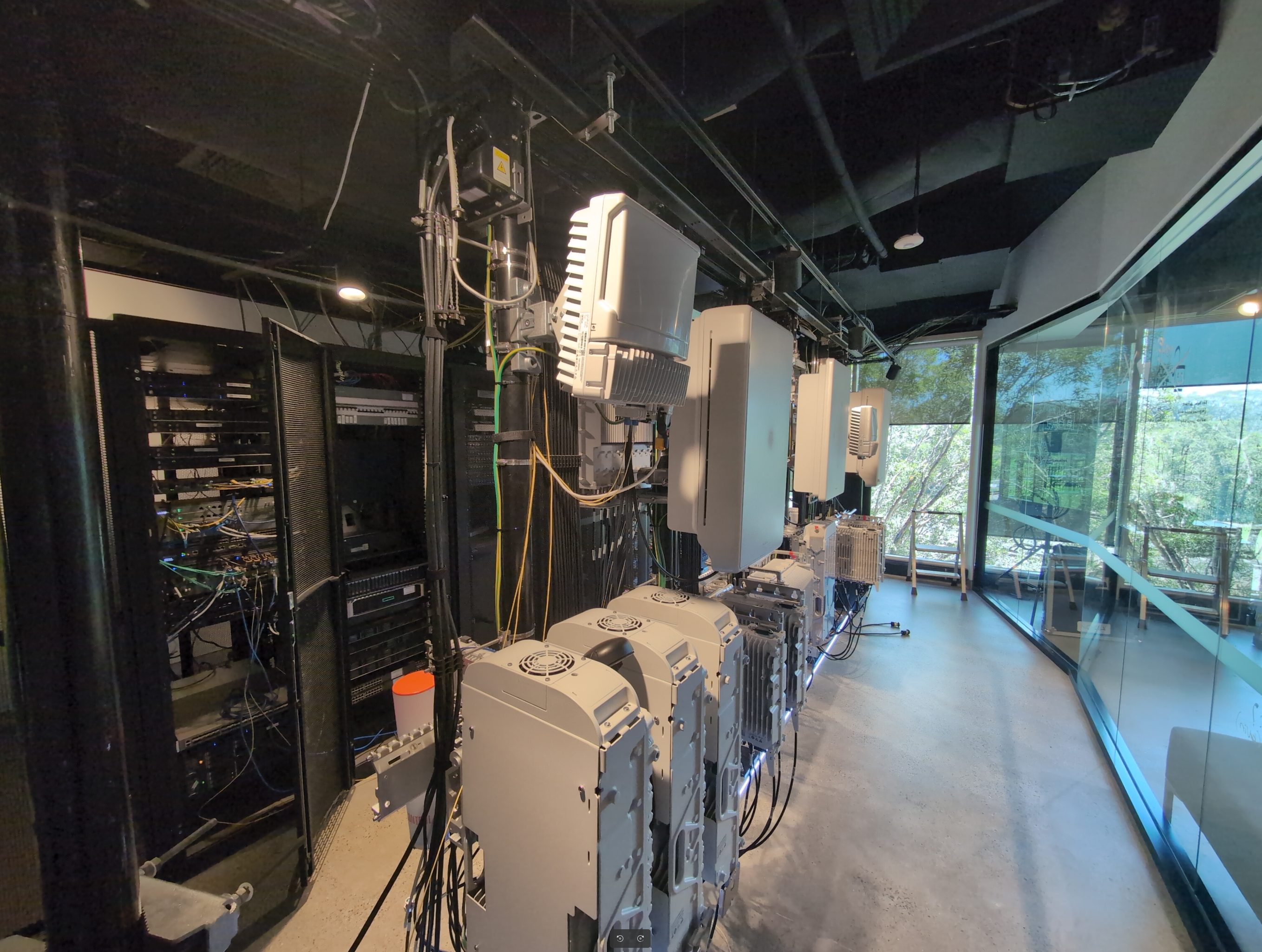
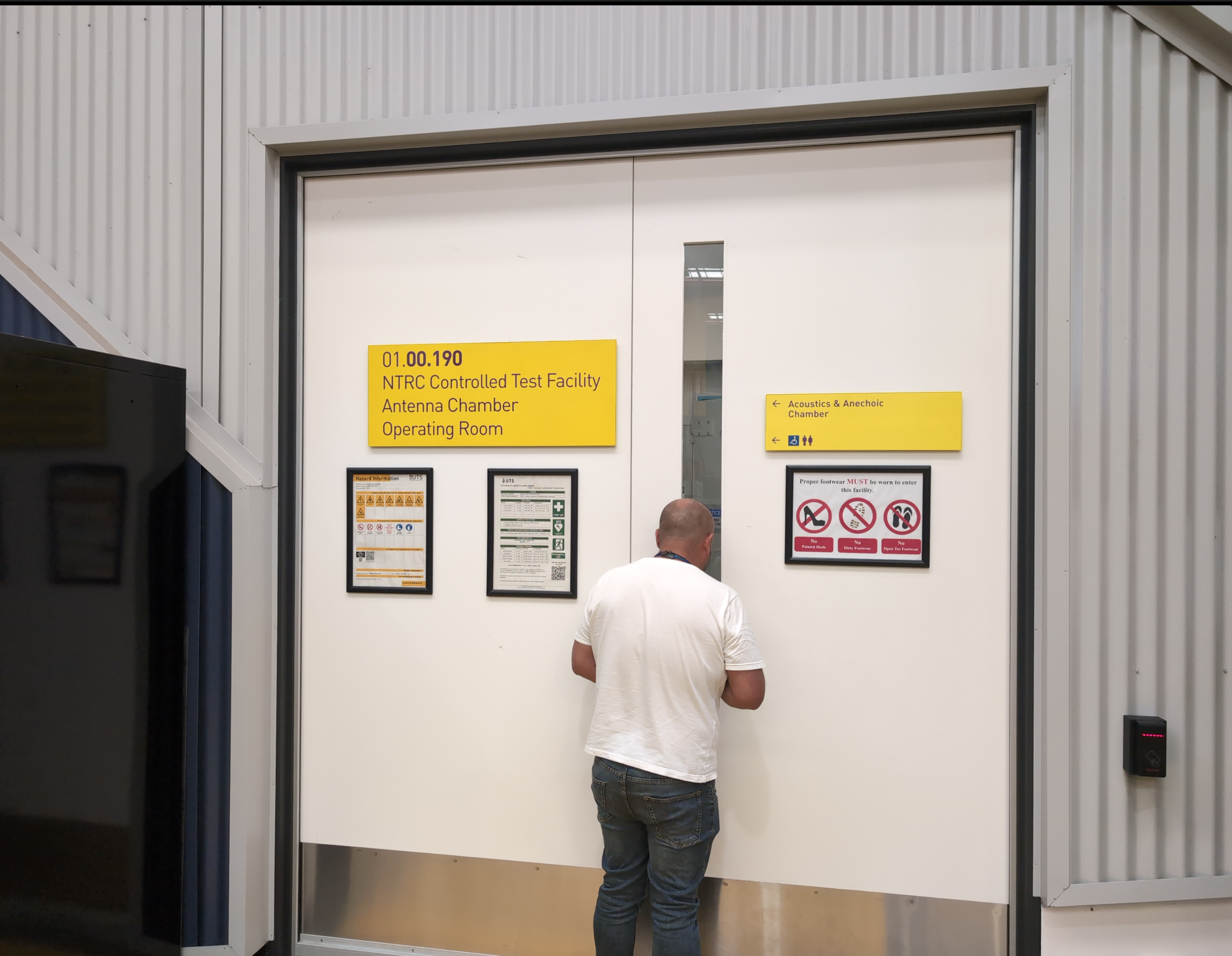
So I reached out to our Nokia account manager and asked if I could visit “The pointy room” – The antenna chamber they’ve got there and Nokia lab.
It did not disappoint.
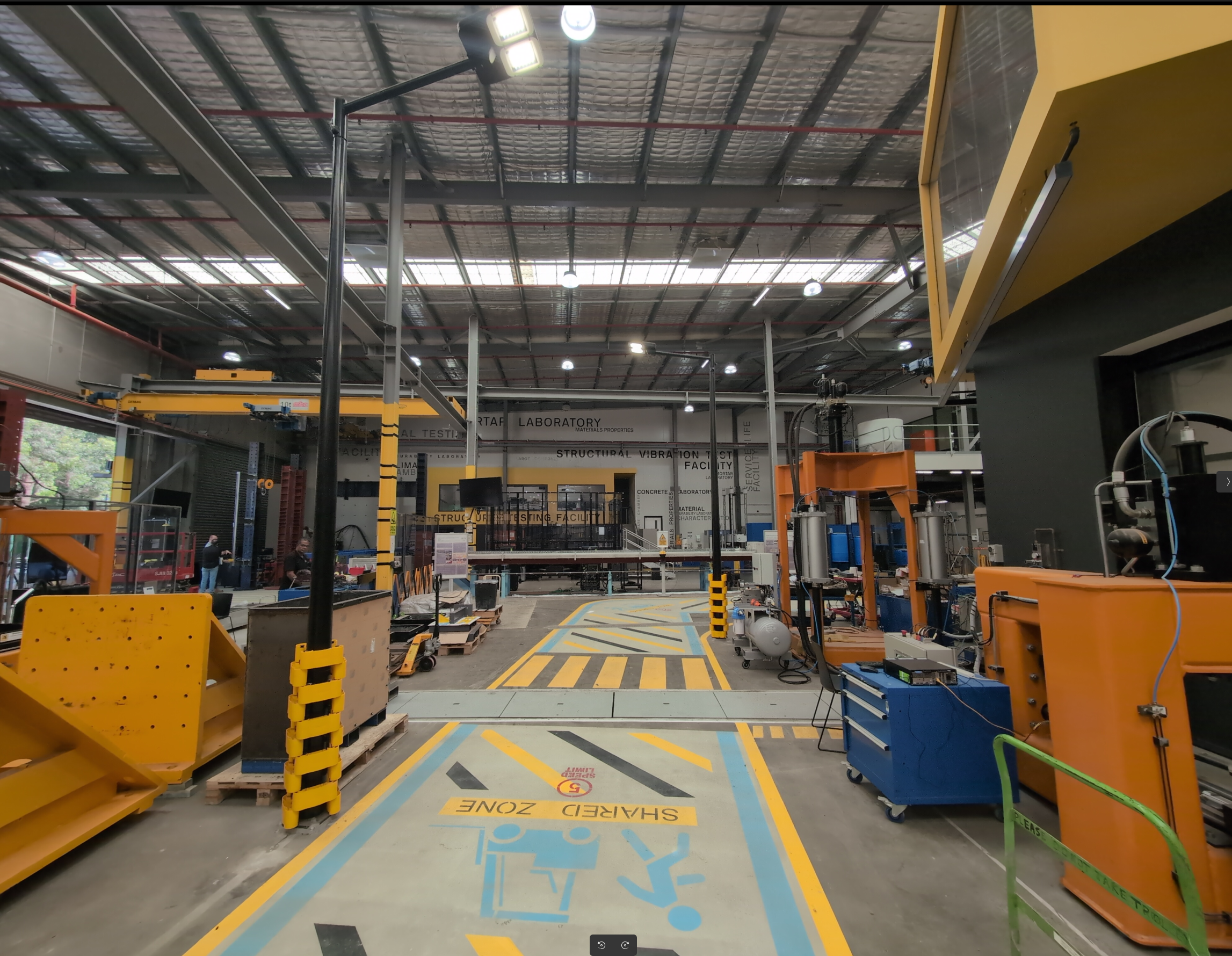
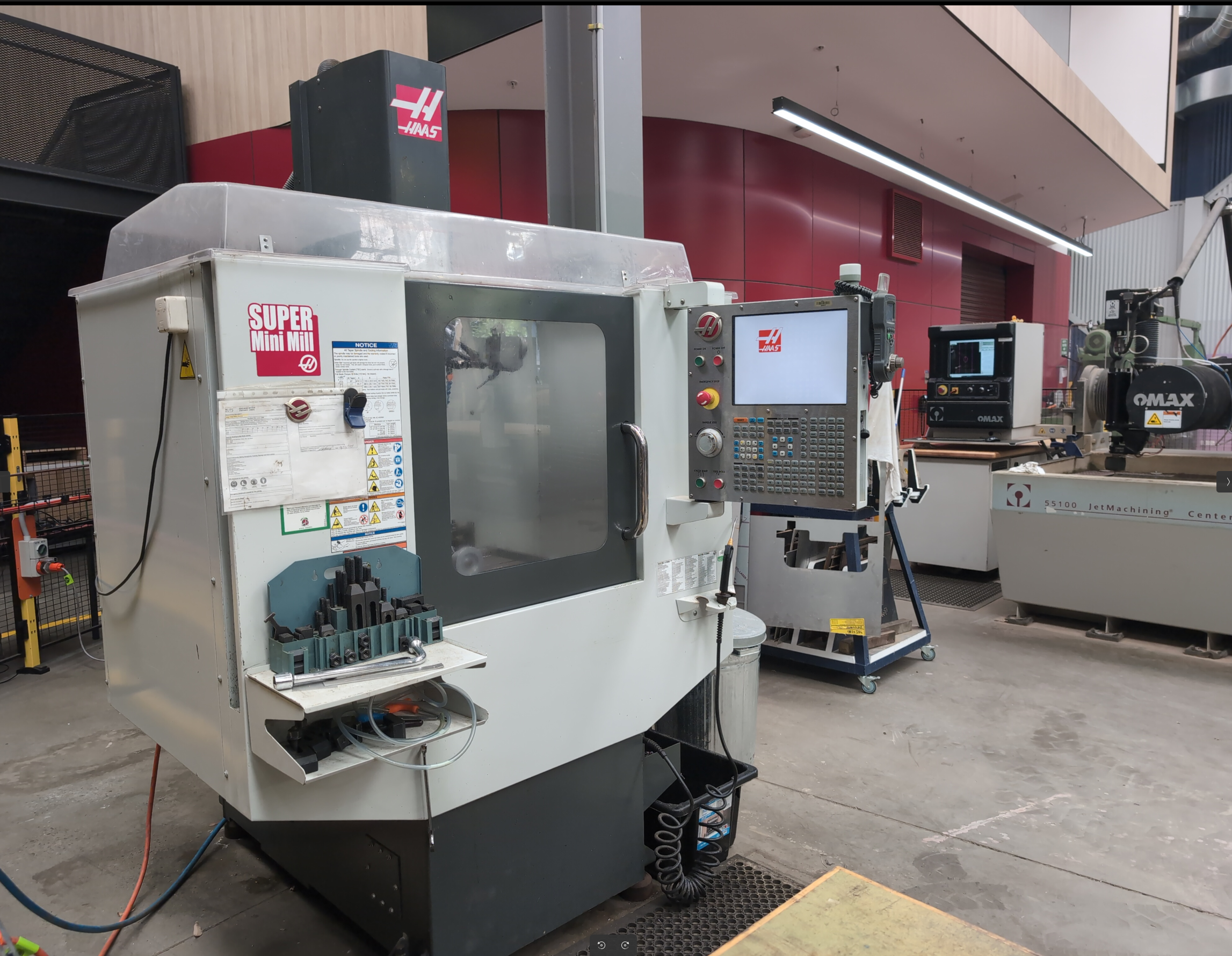
As well as all the fancy RAN kit and pointy room, they’ve got the kind of machine shop I dream of.
Thanks to Paul, Dave and Ed for showing me around.
We also had a few days hiking in the Blue Mountains, not as impressive as RAN kit.
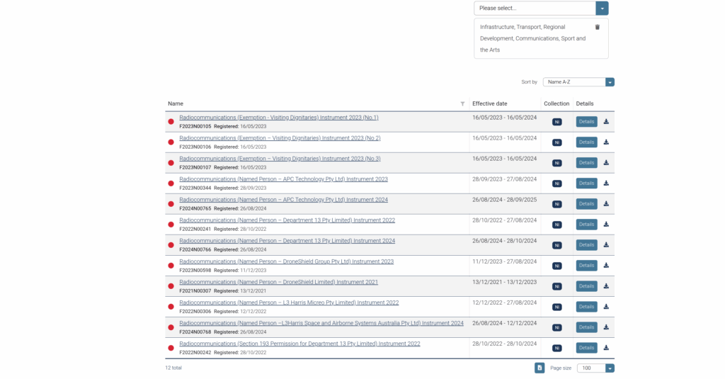
I got this email today from ACMA, the Australian communcations regulator who’s mailing list I subscribe to:
When I first started working, I’d often ride my motorbike to customer job sites with my cabling tools in a milk crate strapped on the back, but at no point did I combine customer cabling with riding the motorcycle – They seem like separate tasks.
So why does a motorbike race except certain people, equipment and cabling from the rules?
Will we see people on bikes traveling at great speed while crunching on Krone?
Leaning into the corners while working on lines?
Well, rather than doing my work I went down the rabbit hole to find out, and it started with ACMA gaving a handy link to the declaration in the email:
Section 54A Exemption – devices used for significant events says:
If you’re just operating your widgets for the purpose of a significant event, it’s cool, you don’t need to worry about complying with ACMA’s Low interference potential devices (LIPD) class license standards.
Section 54A Exemption – devices used for significant events (Some liberty taken)
So why would this exist?
Well, 5 days after the MotoGP wraps up on Philip Island it’s in Malaysia. I assume this loophole exists because there’s a lot of fancy telemetry stuff on the bikes, cameras, engine monitoring, lap time recording, and if MotoGP organizers had to get type-approval for everything and local cabling certification for everything, in every country the operate, when the race moves country to country each week, they’d never get approval for anything.
I did some research to see if this has been used before, and if so where, and came up short, this might be the first time this has been used:
What I did learn is if you’re a big enough wig (For example president of the US), you can get an exemption to the anti-jamming laws, which is used from time to time.
But as for the MotoGP being for their telemetry devices, this is just a guess, if anyone reading this knows definitively how this came to be, and where else this gets used, drop a comment – I’d be curious.
I love Grafana. I love metrics and observability. Nothing is more powerful than being able to see what’s going on inside your network/application/solar setup/weather station – you name it.
It’s never been easier to see what’s going on.
If I wanted to monitor my web app as I onboard more customers, Grafana is the go-to tool, but how was it done before the computer age? Let’s go back to the 1940s and look at how the telephone network handled observability and metrics…
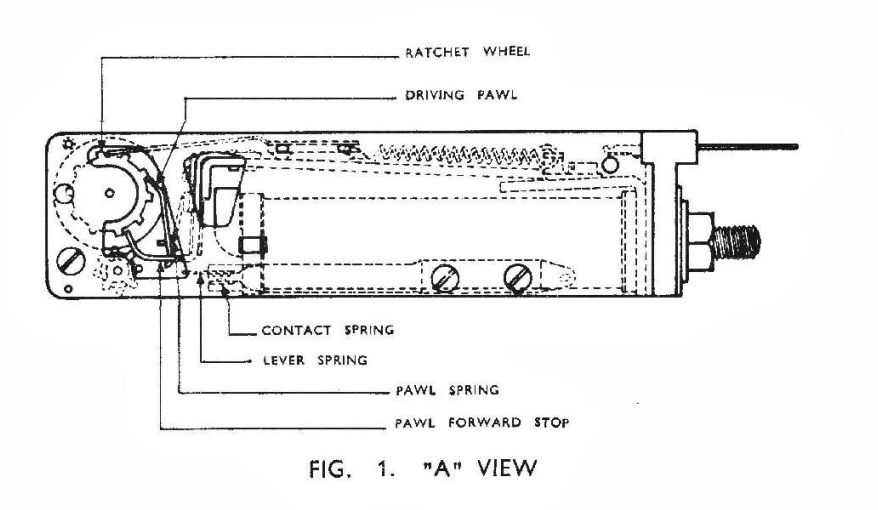
This starts with introducing the “Call Meter”, “Subscriber Meter” or “Subs Meter” for short.
Detail of mechanical call meter Strathfield South Exchange Source – field, field, field and chang’s brilliantly beautiful “That Exchange Project“
The concept is pretty simple. Each telephone service (“subscriber” in telecom parlance) provided by the local telephone exchange gets a subscriber meter or “subs meter”.
When the subscriber (customer) makes a call, and the call is answered, a reverse of polarity on the line ticks the subscriber meter over by one digit.
Each of the meters on the left is a single telephone subscriber, each time they make a call, the meter ticks up by one position. Source – field, field, field and chang’s brilliantly beautiful “That Exchange Project“
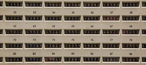
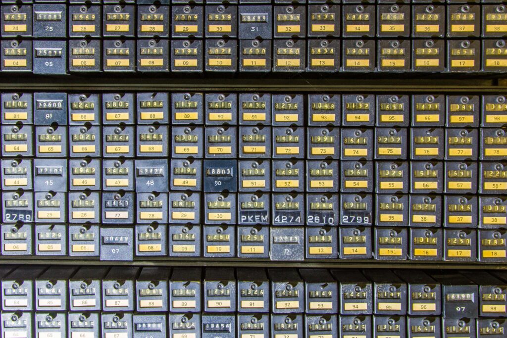
As you can imagine if you’ve got a telephone exchange that serves 10,000 customers, well you need 10,000 subscriber meters…
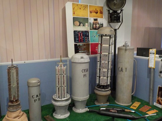
You need a lot of meters… Source – field, field, field and chang’s brilliantly beautiful “That Exchange Project“
At the end of the month, someone takes a photo of all the meters on a film camera, sends it off to a billing center where they develop the photo, then calculate the difference in values from last month’s meter reading photo and this month’s meter reading photo, and bingo – there’s the number of calls the person made. You tabulate the cost on an adding machine and send off the invoice.
Each of the little blocks is a single subscriber to meter and the weird cone thing held is a hood for the camera to photograph the values – Source The Communications Museum Trust
Optional Sidebar for those asking “but what about Long Distance calls where you pay per minute?” – In a world where you pay per local call, regardless of length, this works just fine, but as more complicated scenarios like long distance calling were introduced, this presented a challenge, but this could be solved by reversing the line polarity at predefined intervals, to keep ticking up the subscriber meters during the call. Exchange Clocks provided a number of pulse outputs, like 1 pulse per second, 1 pulse per minute, etc, this 1 pulse per minute signal could be hooked up to the line reversal circuit for long distance calls, to trigger the line reversal every minute. This means if a local call was $0.40 untimed, if you made long distance calls at $0.40 per minute, then you just needed the exchange to reverse the line every minute to pulse the meter. 10 increments on the meter could mean 10 x $0.40 local calls or 10 minutes of $0.40 per minute long distance.
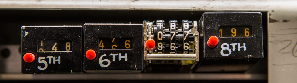
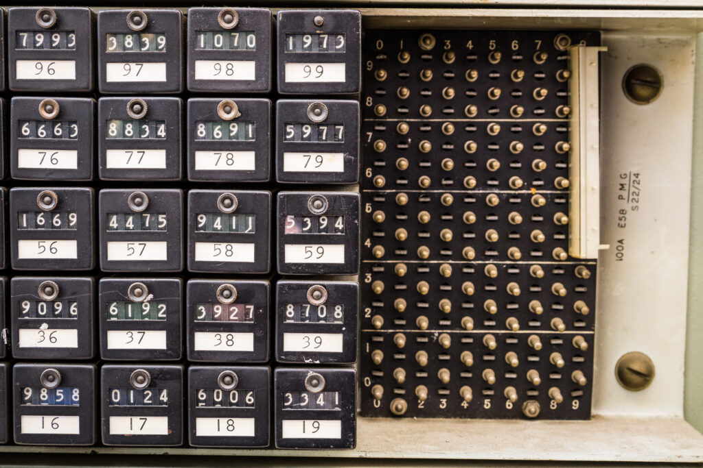
These meters were originally just for metering traffic, but engineers in the telephone network realised they could be used as generic “counters” for just about anything in the telephone network.
Let’s imagine you want to know how often a trunk line to another exchange runs out of capacity, well, you simply wire a meter to get triggered each time that condition happens, now you’ve got a counter for each time that event occurs.
Now let’s say you want to know how often you run out of final selectors, well, through another counter on it.
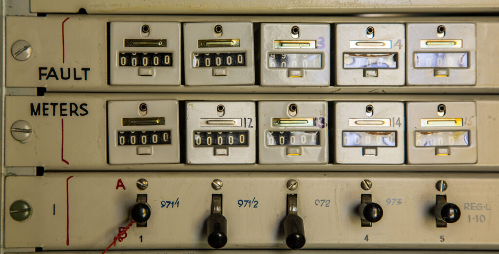
These same meters, can be wired to count fault conditions.
Mechanical fault meters on old step-by-step test desk, Queanbeyan Exchange Source – field, field, field and chang’s brilliantly beautiful “That Exchange Project“
A pencil and a logbook is how you keep track of frequency of the event being triggered, and if you want to graph it out, graph paper, not Grafana.
As telephone systems increased in complexity more and more meters were used to track what’s going on, up until the time that computers could start to handle that process, when “Electronic Customer Metering” came into play with the early Stored Program Control exchanges.
Metering and charging equipment in Blakehurst Exchange Source – field, field, field and chang’s brilliantly beautiful “That Exchange Project“
Observability and Metrics are so important for making software, but every time I define a “counter” in software for an event, I’m always reminded of clicking meters in an telephone exchange, knowing this is how it used to be done.
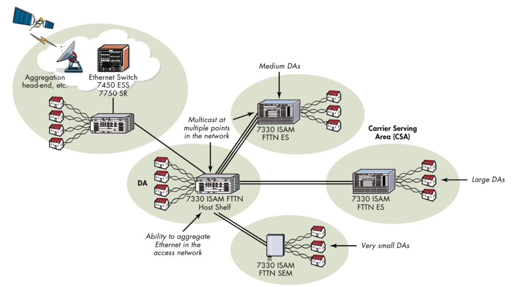
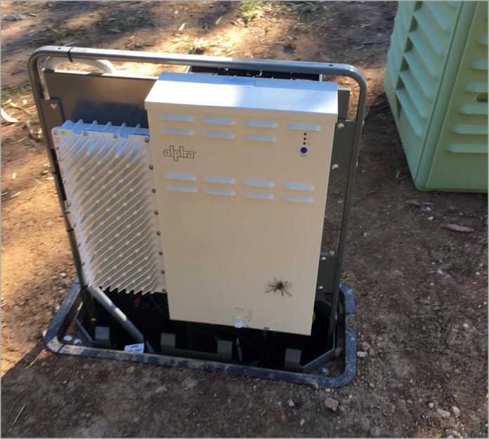
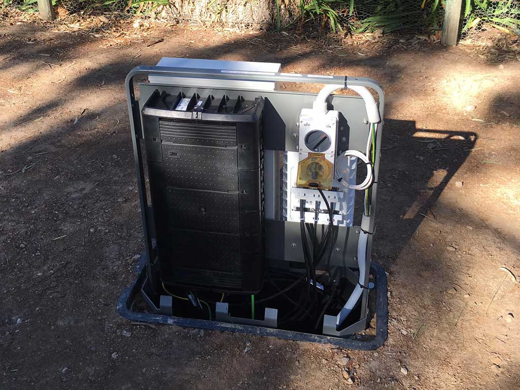
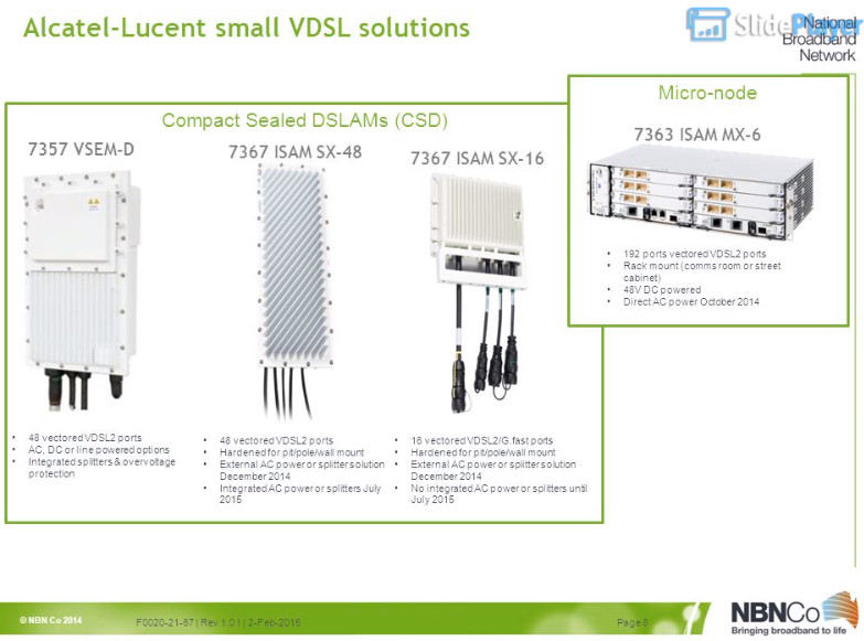
We’ve covered most of the types of NBN Node, but the “Micronode” isn’t something we’ve looked at. Micronodes are “satellites” that hang off a larger Nokia ISAM and act as NBN FTTN DSLAMs.
In NBN documentation these are referred to as “Compact Sealed DSLAMs” or CSDs, and in Nokia/Alcatel documentation these are called Sealed Expansion Modules (SEMs) – Regardless of what you call them, they act as 48 port VDSL capable DSLAMs like rest of the Nokia / Alcatel ISAM family that are used for FTTN.
They are similar in concept to the NBN FTTC program, except these units are not reverse powered, and they have a higher subscriber count.
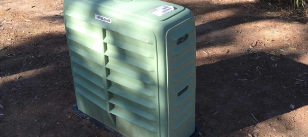
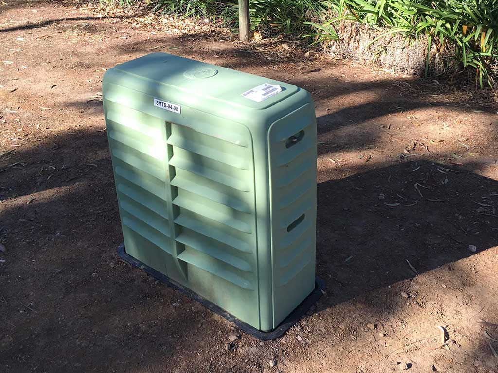
They’re housed in the green cabinets that were used for the HFC / Pay TV networks installed in some locations underground.
The CSD are a Nokia 7367 ISAM SX-48V (White box with the heat sink on the left of the photo below) which is connected directly back to the nearest exchange.
There is also an internal PSU with batteries powered from the incoming unmetered AC supply and a PSU is supplied by Alpha technologies in the photo on the right (With the spider).
On the flip side of the unit is where the copper pairs come in, and the DSLAM X-Pairs go out, and a small fibre splice tray.
A totally complete history and not just something I learned from a fellow phone nerd who’s been around a lot longer than me...
In the early days of telephony voice calls were made by signaling to an operator who would connect your call.
Around the turn of the century the first “automatic” exchanges began to open. This meant that a subscriber could complete their own call, by directly dialing the digits of the party the want to speak to, and getting through, without a human operator “plugging up” the call.
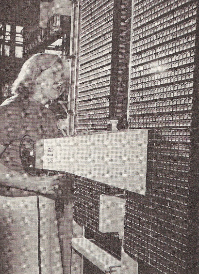
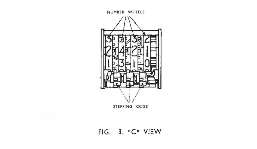
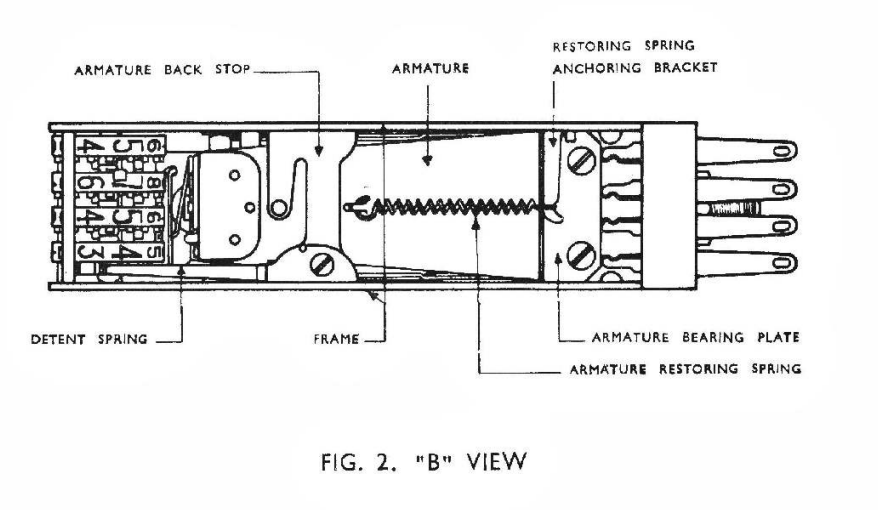
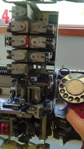
The first type of switches used to provide “automatic” exchange capability were Strowger type switches, they translated the pulses from a rotary dial phone into physical movements on a switch to find and select the line you want.
As it happens I have one of these old switches, here’s what happens when you let go of the dial.
People who were born before touch tone phones can tell you about how you can dial a phone number without using the dial at all. By mashing the hook switch really quickly. If you want to dial a 3 you mash the hook switch 3 times, then wait a second, then to dial a 5 smash the hook switch 5 times, etc, etc.
A quirk of this is that higher numbers, are harder to dial, you just need one pulse of the hook switch in a second to dial a 1, but you need 10 pulses to dial a 0. This means a phone dial that’s running too slow can dial the lower digits, but not the higher digits, as it can’t pulse out the required number of pulses is the time allotted (a smidge over 1 second per digit).
Initially exchanges only connected local calls, but with the introduction of Subscriber Trunk Dialing (STD), subscribers could call from one exchange to another without an operator.
This led to national dialing plans being developed, ensuring uniqueness of numbers across the whole of the phone network, and where possible, lower numbers were used, Australia for example has area codes 02, 03, 07 and 08 (with the majority of the population living in the 02 and 03 area codes).
Now imagine you’re the government owned phone company, tasked with creating a single number for emergency services, 123, 111, etc, etc, are all taken up, as these are the most reliable numbers to dial and were used long ago.
Instead you go to the other end, the UK with 999 and Australia with 000 (911 is a different kettle of fish).
Except in New Zealand.
111 was specifically chosen to be similar to Britain’s 999 service, but NZ has some odd peculiarities.
The NZ dials are identical to the standard dial except for the finger plate label.
With pulse dialing, New Zealand telephones pulse “in reverse” to the rest of the world. Dialing 0 on a phone in the rest of the world, sent ten pulses down the line. But dialing a 0 on a phone in NZ sent one pulse down the line. The same for all the other numbers. The phones weren’t different – Just the labels.
Hence the reason why ‘Emergency’ services were on 111 in NZ (but actually pulsed 999) as the exchanges originated in those days from the UK where 999 was (and still is 999).
In the early years of 111, the telephone equipment was based on British Post Office equipment, except for this unusual orientation. Therefore, dialing 111 on a New Zealand telephone sent three sets of nine pulses to the exchange, exactly the same as the UK’s 999.
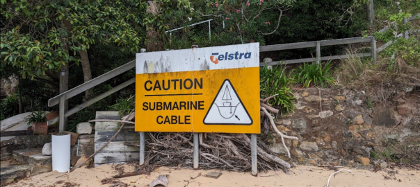
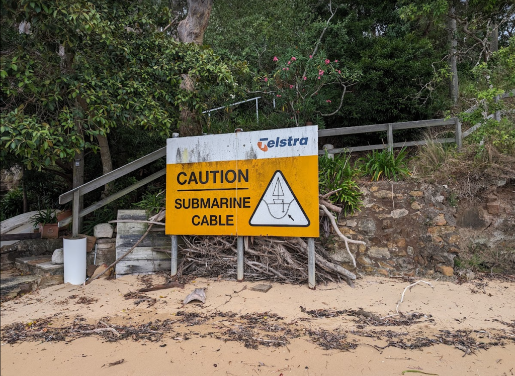
Recently I took a week off work and went hiking around the Hawkesbury river in NSW.
This did not mean I stopped thinking about telecom.
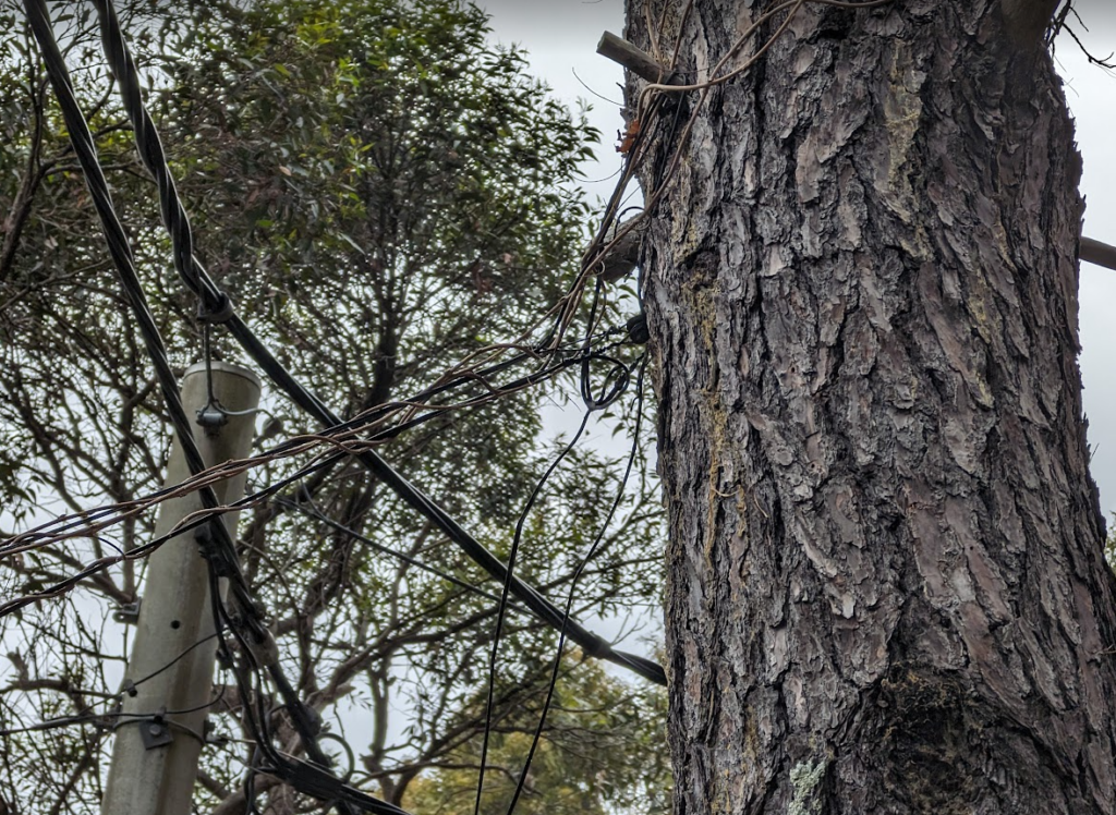
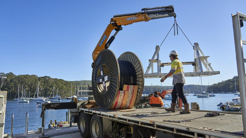
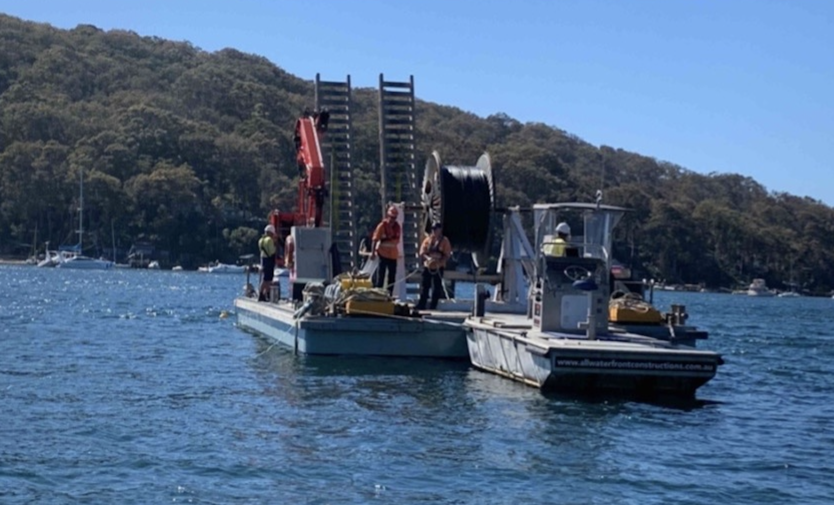
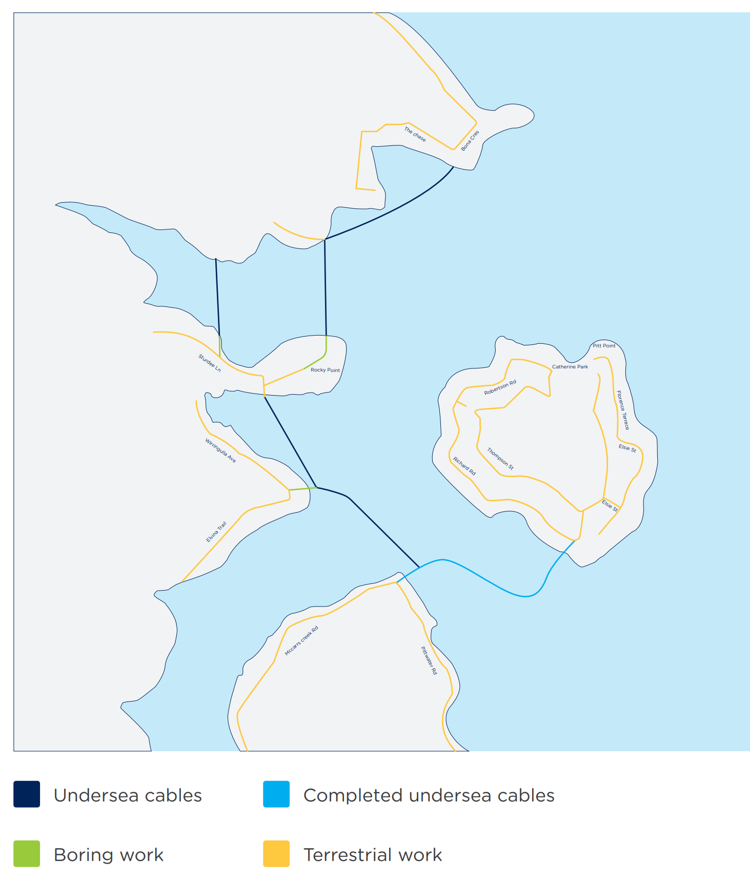
There’s a lot of beautiful bushland and some fancy houses nestled into the area, a good chunk of which are not accessible by road at all, with the only way to access them being by boat or a long hike along a bush track.
No fancy erbium-doped fiber amplifiers here though, just regular GPON laid on the riverbed.
Telstra / Telecom had previously laid a copper 100 pair (seemingly just regular gel filled cable directly on the riverbed without any protection) to service the area, and then aerial distribution along the tracks connecting the homes.
NBNco it seems opted for a slightly safer approach and used Protectorshell articulated pipe to protect the cables in the water / on the beaches.
Strange tree roots – NBN Articulated pipe on the left with the old copper 100 pair on the right
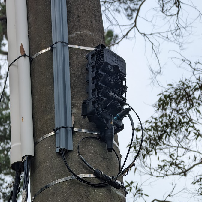
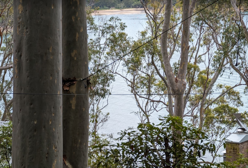
Once the cables land it’s back to regular NBN Aerial fiber runs, with DPUs on the power poles.
Apart from a few interesting catenary runs, and the fact there are no roads, once the fibre lands it’s very much a standard aerial NBN deployment.
There’s some great pics below from the supplier websites and local news site:
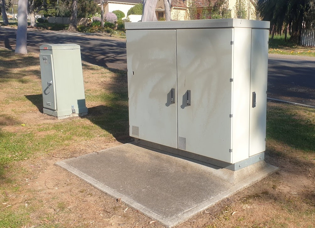
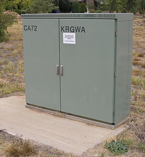
The gray telecom cabinets and pillars can be seen in suburbs across Australia, along rail corridors and even overseas.
But what do they do? What’s the difference between a pillar and a cabinet? Are they still used today? What’s inside? Why are they such an important part of the network?
What are they?
In a nutshell, they’re weatherproof (if properly cared for) enclosures for cross connecting (jumpering) cables.
This means that rather than doing the jumpering / cross connecting services in a dirty pit, a cabinet can be opened and the connection made quickly, in a clean, easily accessed, above ground housing.
They utilise a really clever design, that was the result of a competitive design process in the 1950s.
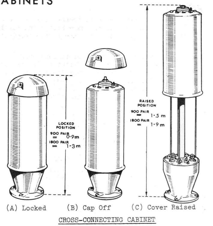
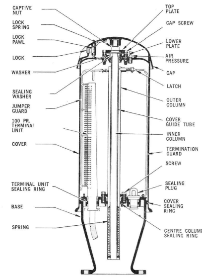
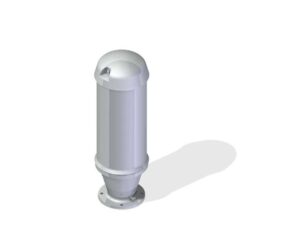
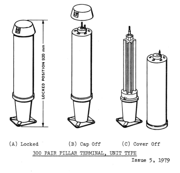
The schrader valve (bike valve) at the top allows the units to remain pressurized, this means in areas subject to flooding or for pressurised cables, the pillar remains water tight ( although the practice of sealing them again with air isn’t very common anymore).
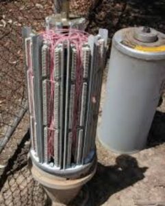
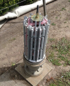
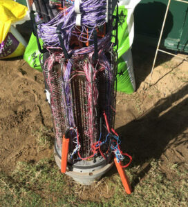
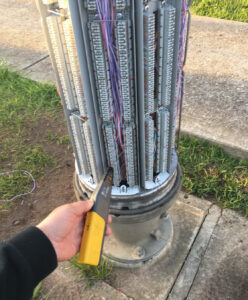
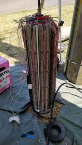
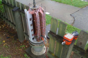
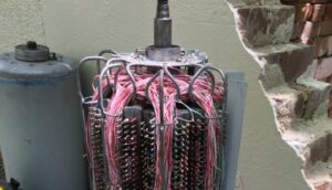
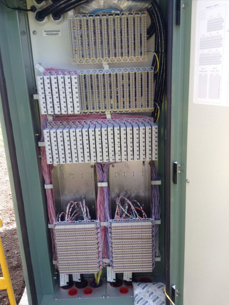
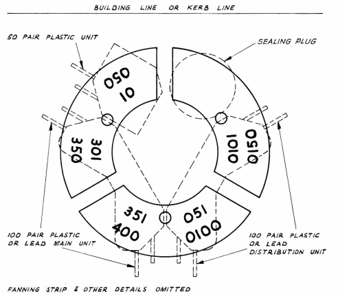
When the aluminum top plate is unlocked and spun off the threaded fitting, the linesworker can unscrew the big nut on top, and lift up the cover, which locks open at the top, revealing the terminal units (either solder tag blocks or Krone blocks) inside the unit.
900 pair IDC1800 pair tag block with Loopalines1800 pair with IDC and F-Set1900 pair tag block900 pair in a fenceCable management
Jumpering a service is just a matter of opening up the cabinet, finding the A side and the B side, and running jumper wire through the built in cable management loops from one side to the other.
Each of the Terminal Units is a pre-terminated strip with a few meters of tail, which is fed through the base of the pillar to a nearby pit where they can join 1 to 1, out onto the underground cables, this means the units can be upgraded for additional capacity as needed.
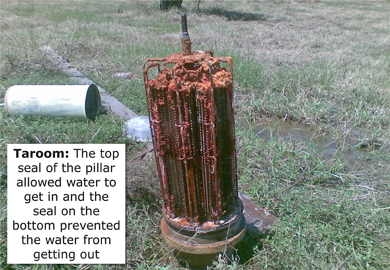
While pressurised they are IP67 rated, but this only goes so far, check out this Telstra photo from Queensland Floods in 2010 from Taroom.
Why were they needed?
Cables are expensive. We want to minimize excess unused pairs and use the existing pairs with maximum flexibility and efficacy
Opening joints costs time, money, and risks disturbing other services. We want to avoid opening joints
Troubleshooting is also time consuming and costly. A convenient test point is needed for isolating where in a cable a fault lies. (Main Cable, Distribution Cable, etc)
Easily use gas/air filled cables, without having to constantly open and reseal cables them to splice in new joins / jumpers
Cabinet vs Pillar
Cabinets and Pillars look the same, but the hints as to their purpose are in their location and what’s sprayed on them in faded paint.
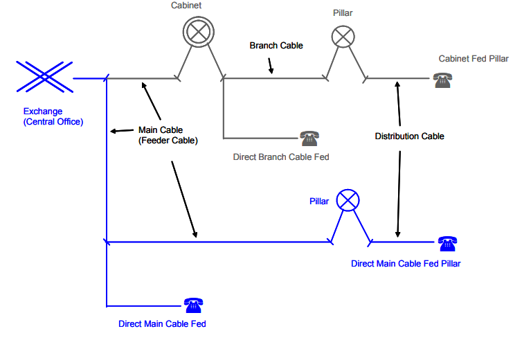
Pillars are used for cross-connecting main cables (“M” Pair from the exchange) with distribution cables (to subscribers “O” pairs which run down the street to the pit in the front of your house).
Pillars are generally stenciled with a “P” and an number, or just the DA (Distribution Area) number.
Cabinet are a more flexible setup where you can connect cables between Pillars, akin to a root & branch approach.
Cabinets cross connect Main Cables (“M” pair to the exchange), with Branch Cables (“B” Pair from the Cabinet to Pillar) and Distribution cables (“O” pair to the customer).
Cabinets are stenciled with the prefix “CA” and a number, and exist in the 900 and 1800 pair variants, where one is just taller than the other.
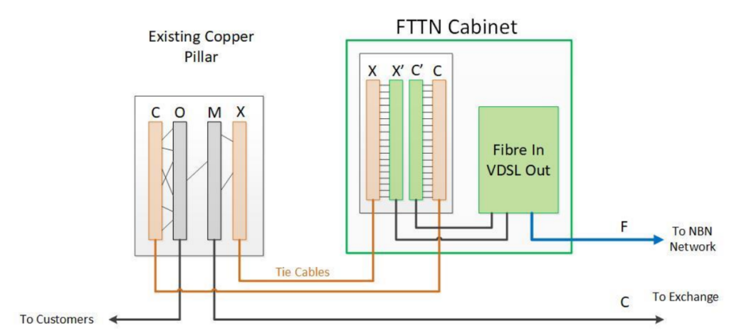
The blue example is direct from the Main Cable to the Pillar, while Cabinets are used in the black example.
This means the distribution can go via a Cabinet to the Pillar to the Customer, as shown in the top /grey lines in the diagram.
Exchange Main Cables (Main Cables / M-Pairs) go to Cabinets
Cabinets connect to Pillars (Branch Cables / B-Pairs)
Pillars connect (Distribution Cables / O-Pairs) that run through the pits outside houses
Inside the Openable Joint in the pit is used to connect the lead in cable from a subscriber’s premises
Alternatively, the Cabinet may be bypassed and a direct cable goes between the Exchange and the Pillar, in that scenario it looks like the one show in blue lines on the diagram.
Exchange Main Cables (Main Cables / M-Pairs) go to Pillar
Pillars connect (Distribution Cables / O-Pairs) that run through the pits outside houses
Inside the Openable Joint in the pit is used to connect the lead in cable from a subscriber’s premises
Display of 300, 900 and 1800 pair pillars and cabinets at the former Telstra Museum in Hawthorn
The Cabinet to Pillar model fell out of favor due to its increased complexity. While it was cheaper to deploy the network using cabinets that cascaded down to feed pillars (you would only have to install enough cable for the “here and now” and could add additional Main & Branch cables as needed in a targeted manner) the move to outsourced lineswork for Telecom found that any increased complexity, led to additional operational cost that outweighed the capital savings
Use in the “Modern” Copper Customer Access Network
Pillars are still used in areas of Australia where NBNco have deployed Fibre to the Node.
This means a customer with a traditional POTS line (M-Pair from the Exchange, C-Pair from the Cabinet to the Pillar, O-Pair from the Pillar to the Pit, and then the lead-in into their property) has the O-Pair and C-Pair buzzed out on the pillar, and then routed through the X-Pair and the C-Pair on the Node.
This puts the DSLAM in the Alcatel ISAM inline with the customer’s existing copper loop to the Exchange. The main cable comes from the exchange onto the M-Pair blocks in the Pillar, is jumpered onto the X-Pairs which go through the DSLAM, and come out as C-Pairs back onto the pillar. The C-Pair is then jumpered back to the Customer’s O-Pair and bingo, the FTTN cabinet is inline with the copper loop.
However as the PSTN services get dropped, the Main / M-Pair to the exchange can eventually be removed and the cables removed, meaning the connection just goes from the C pair for VDSL out into the O pair to the customer.
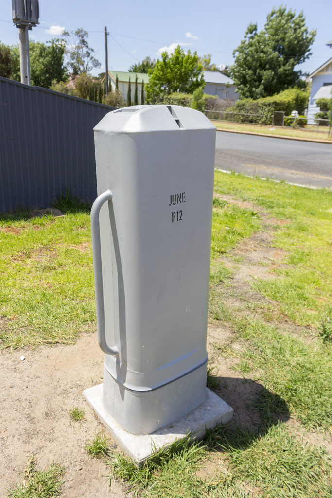
As part of the NBN migration some pillars were upgraded to include IDC / Punch Down blocks, and a rectangular version of the pillar was introduced.
NBN pillar
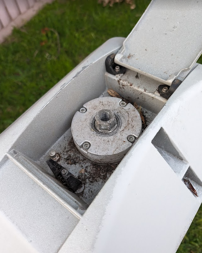
Oddly, these rectangular covers, do not have rectangular units inside, but rather cylindrical ones, just like the pillars of old.
This does fix the missing lids issue – The lid is captive, but I’m not sure what other design improvements this introduces – if anyone has the insight I’d be keen to hear it!
At long last, more and more Australians are going to have access to fibre based access to the NBN, and this seemed like as good an excuse than any to take a deep dive into how NBN’s GPON based fibre services are delivered to homes.
Let’s start in your local exchange where you’ll likely find a Nokia (Well, probably Alcatel-Lucent branded) 7210 SAS-R access aggregation switch, which is where NBN’s transmission network ends, and the access network begins.
It in turn spits out a 10 gig interface to feed the Optical Line Terminal (OLT), which provides the GPON services, each port on the OLT is split out and can feed 32 subscribers.
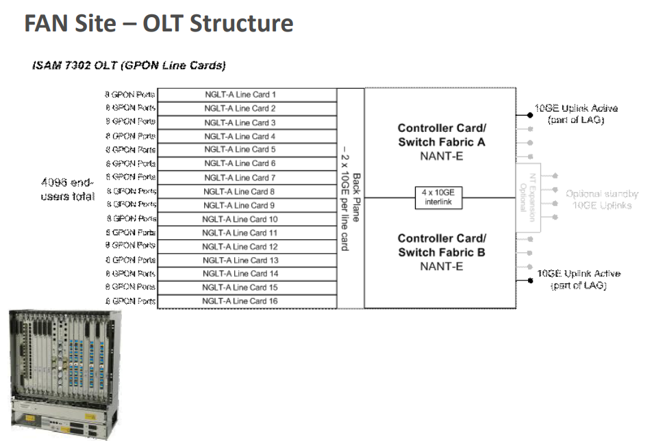
In NBN’s case, Nokia (Alcatel-Lucent) 7302, and rather than calling it an OLT, they call it a “FAN” or “Fibre Access Node” – Seemingly because they like the word node.
Each of the Nokia 7302s has at least one NGLT-A line card, which has 8 GPON ports. Each of the 8 ports on these cards can service 32 customers, and is fed by 2x 10Gbps uplinks to two 7210 SAS-R aggregation switches.
The chassis supports up to 16 cards, 8 ports each, 32 subs per port, giving us 4096 subscribers per FAN.
In some areas, FANs/OLTs aren’t located in an exchange but rather in a street cabinet, called a Temporary Fibre Access Node – Although it seems they’re very permanent.
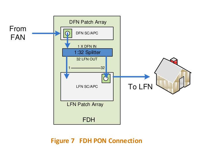
In reality, each port on the OLT/FAN goes out Distribution Fibre Network or DFN which links the ports on the OLTs to a distribution cabinet in the street, known as as a Fibre Distribution Hub, or FDH.
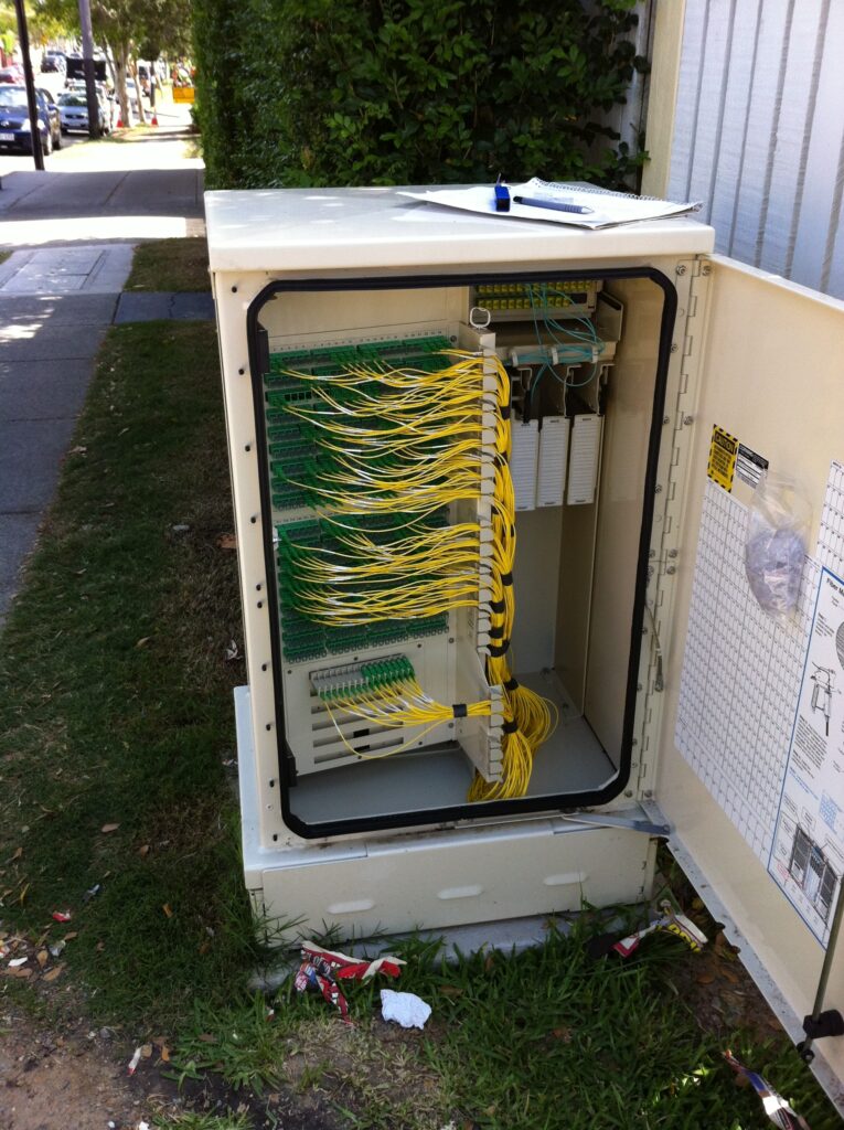
If you look in FTTH areas, you’ll see the FDH cabinets. The FDH is essentially a roadside optical distribution frame, used to cross connect cables from the Distribution Fibre Network (DFN) to the Local Fibre Network (LFN), and in a way, you can think of it as the GPON equivalent of a pillar, except this is where we have our optical splitters.
Remember when we were talking about the FAN/OLT how one port could serve 32 subscribers? We do that with a splitter, that takes one fibre from the DFN that runs to the FAN, and gives us 32 fibres we can could connect to an ONT onto to get service.
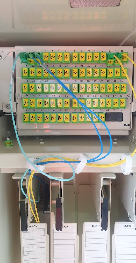
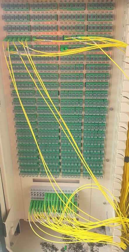
Inside the FDH showing the Distribution Fibre Network (DFN) connecting to the optical splitters belowDistribution Fibre Network with up to 576 fibres running out and down streets, with parking below
The FDH cabinets are made by Corning (OptiTect 576 fibre pad mounted cabinets) and you can see in the top right the Aqua cables go to the Distribution Fibre Network, and hanging below it on the right are the optical splitters themselves, which split the one fibre to the FAN into 32 fibres each on SC connectors.
These are then patched to the Local Fibre Network on the left hand side of the cabinet, where there’s up to 576 ports running across the suburb, and a “Parking” panel at the bottom where the unused ports from the splitter can be left until you patch the to the DFN ports above.
The FDH cabinets also offer “passthrough” allowing a fibre to from the FAN to be patched through to the DFN without passing through the GPON splitter, although I’m not clear if NBN uses this capability to deliver the NBN Business services.
But having each port in the FDH going to one home would be too simple; you’d have to bring 576 individually sheathed cables to the FDH and you’d lose too much flexibility in how the cable plant can be structured, so instead we’ve got a few more joints to go before we make it to your house.
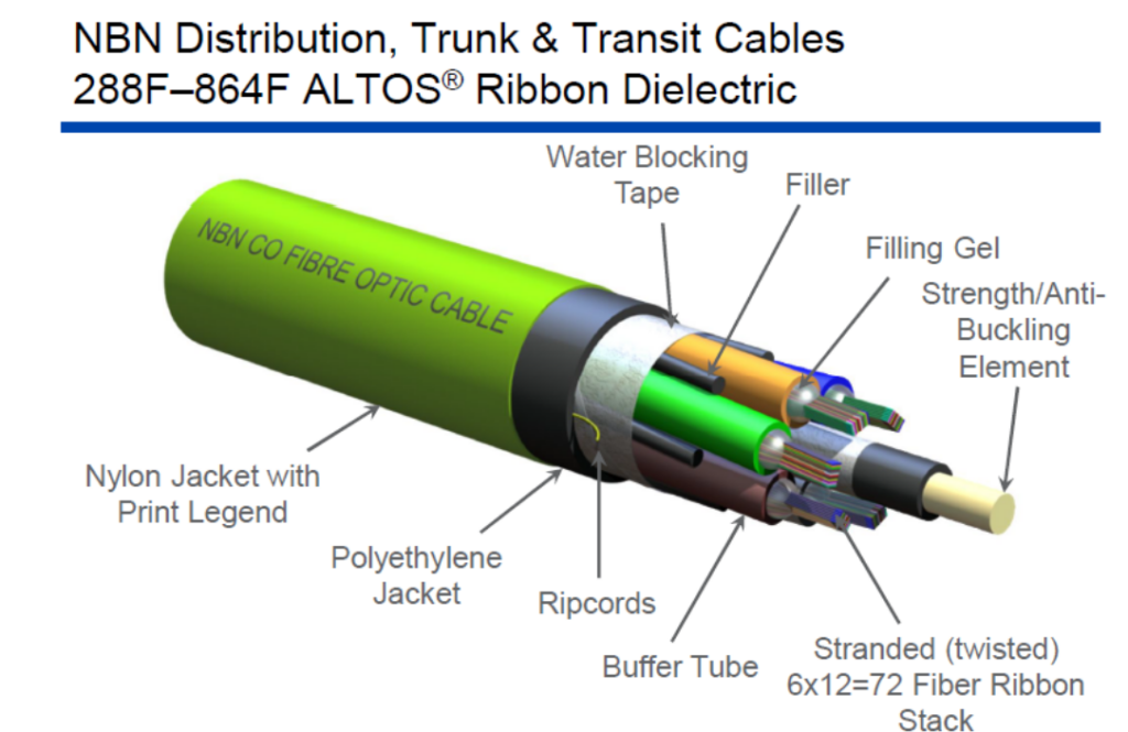
From the FDH cabinet we go out into the Local Fibre Network, but NBN has two variants of LFN – LFN and Skinny LFN. The traditional LFN uses high-density ribbon fibres, which offer a higher fibre count but is a bit tricker to splice/work with. The Skinny LFN uses lower fibre count cables with stranded fibres, and is the current preferred option.
The original LFN cables are ribbon fibres and range from 72 to 288 fibre counts, but I believe 144 is the most common.
These LFN cables run down streets and close to homes, but not directly to lead in cables and customer houses.
These run to “Transition Closures” (Older NBN) or “Flexibility Joint Locations” (FJLs – Newer NBN)
While researching this I saw references to “Breakout Joint Locations” (BJLs) which are used in FTTC deployments, and are a Tenio B6 enclosure for 2x 12 Fibers and 4x 1 Fibers with a 1×4 splitter.
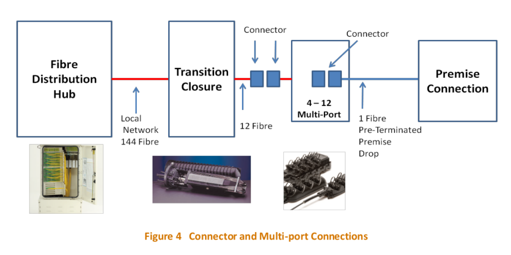
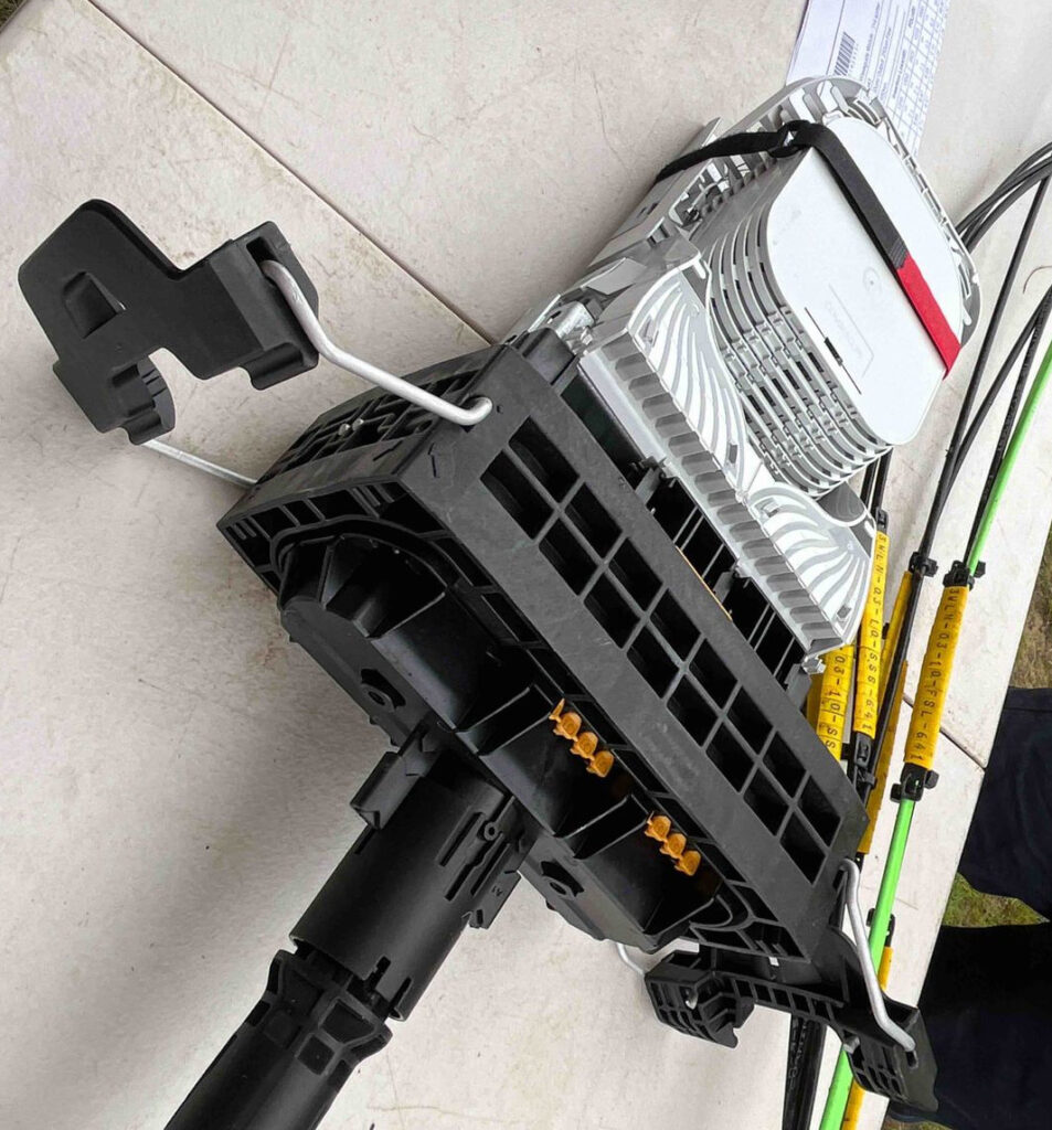
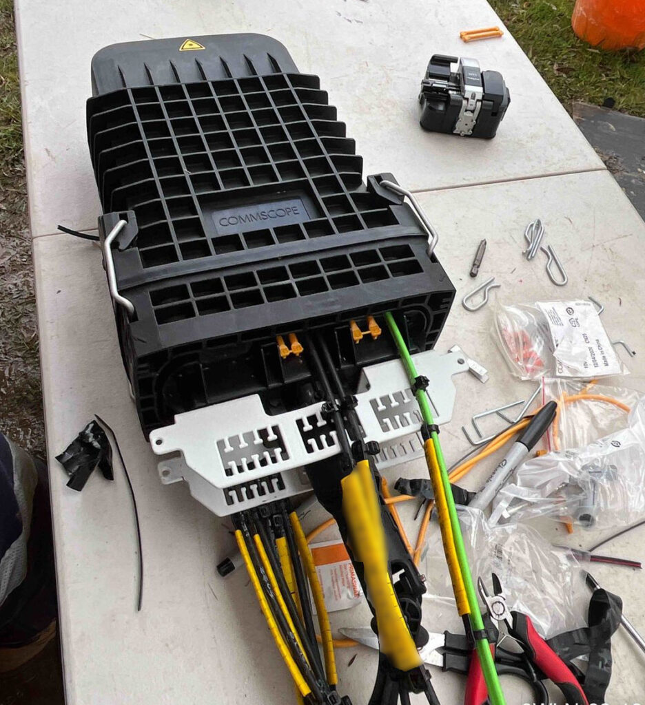
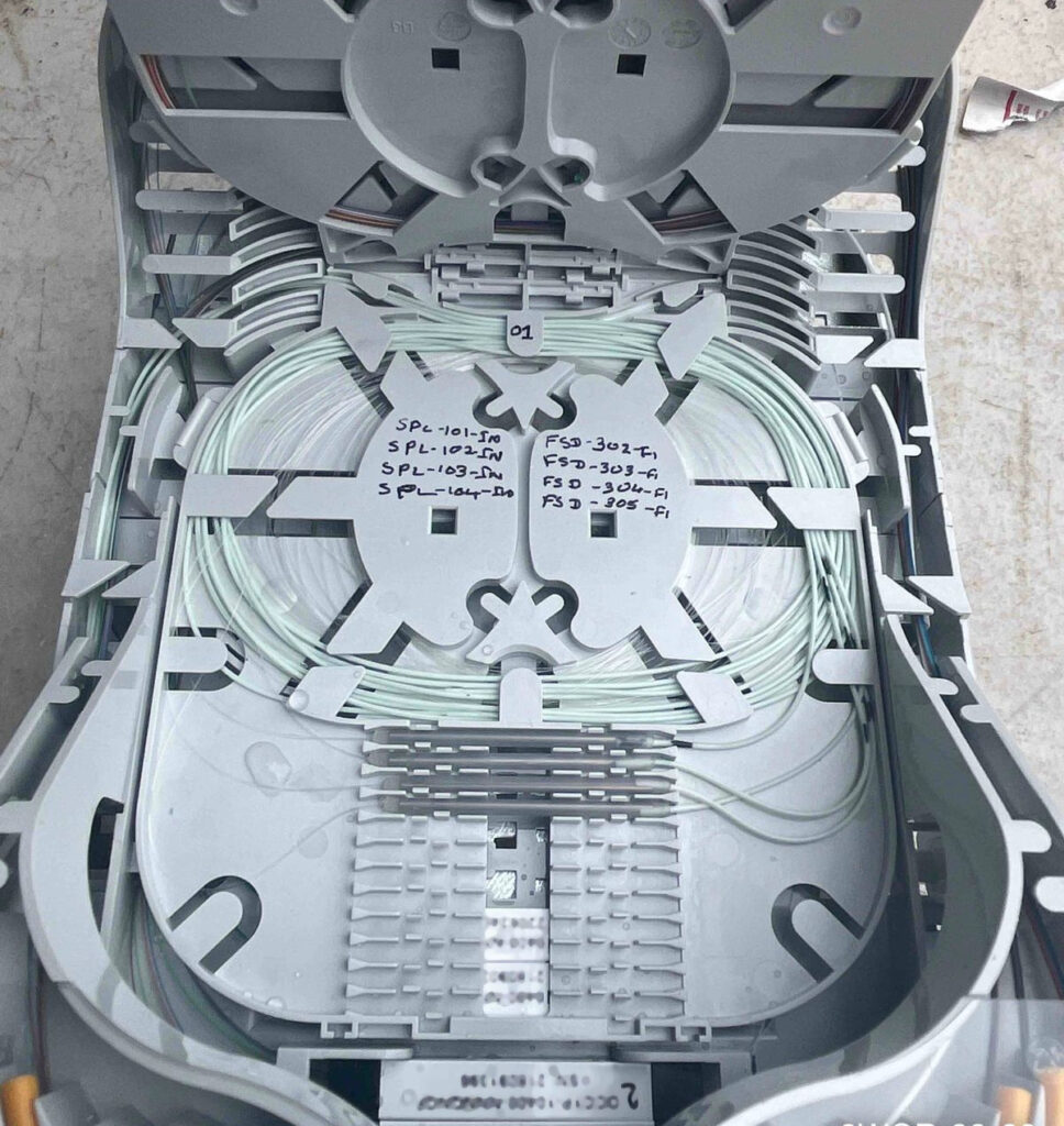
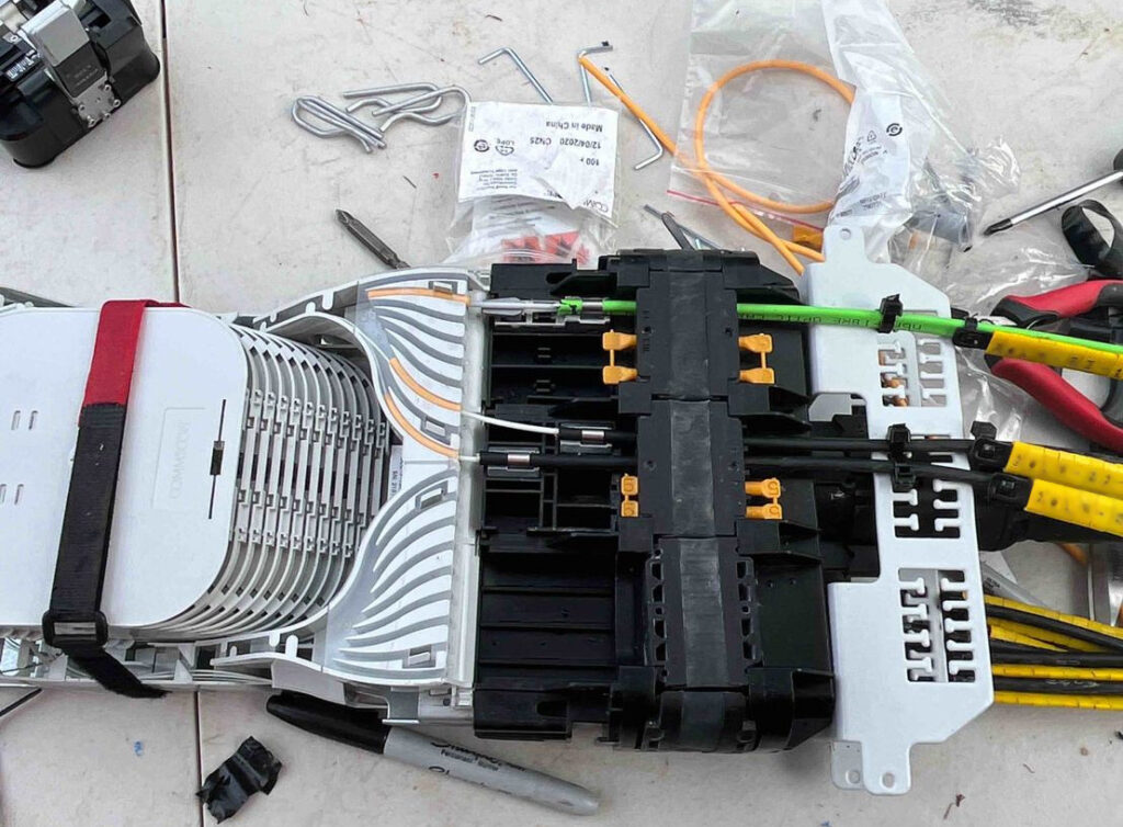
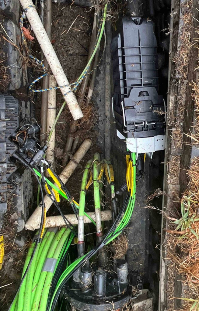
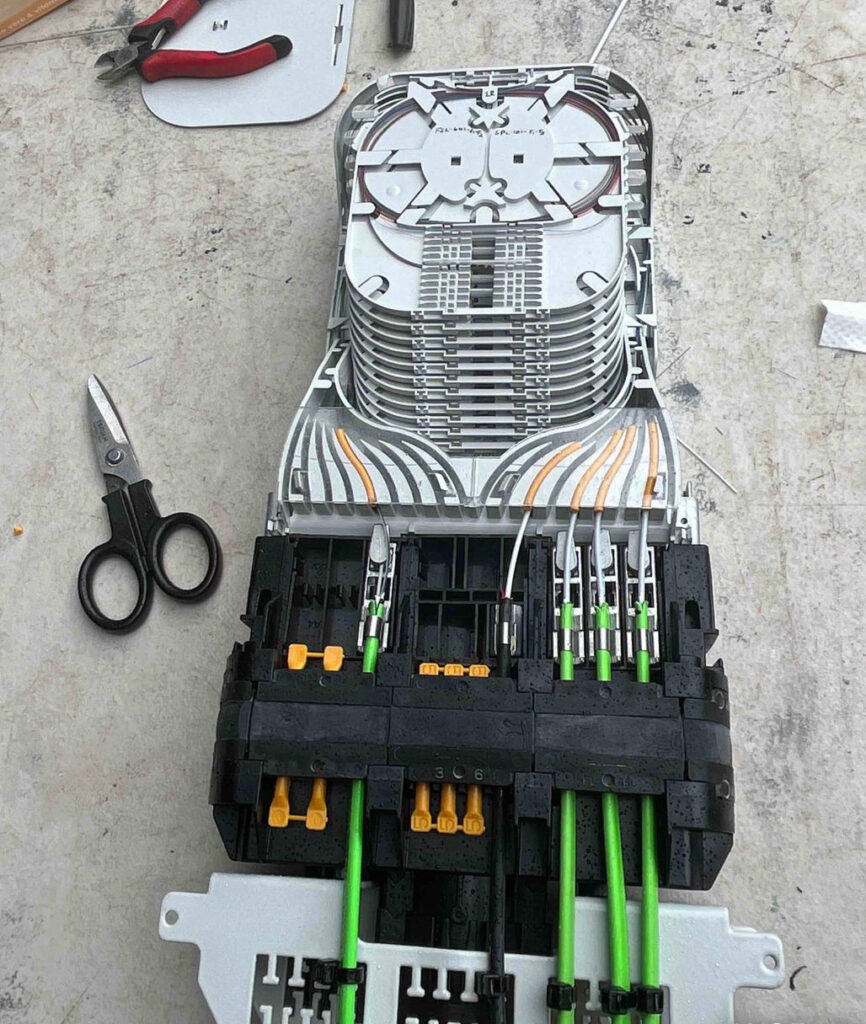
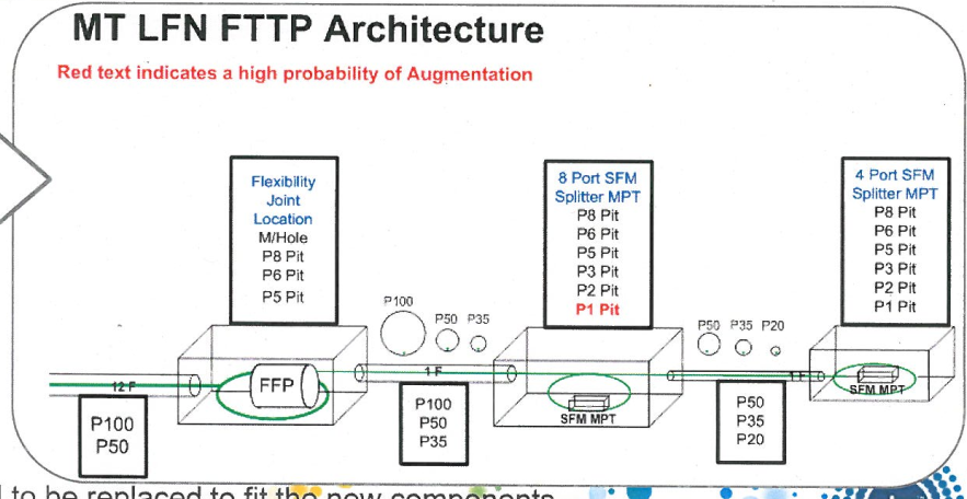
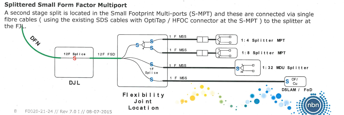
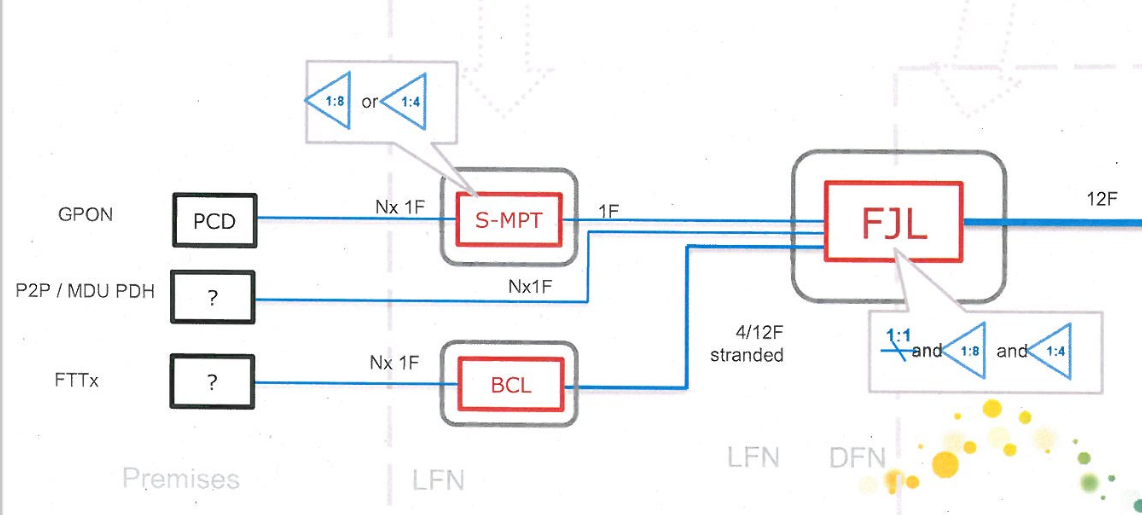
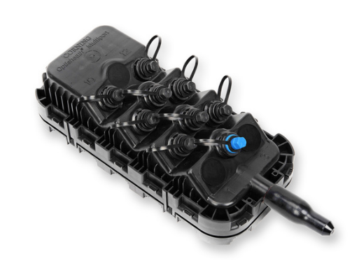
The FJLs are TE Systems’ (Now Commscope) Tenio range of fibre splice closures, and they’re use to splice the high fibre count cable from from the FDH cabinets into smaller 12 fibre count cables that run to multiple “Splitter Multi Ports” or “SMPs” in pits outside houses, and can contain splitters factory installed.
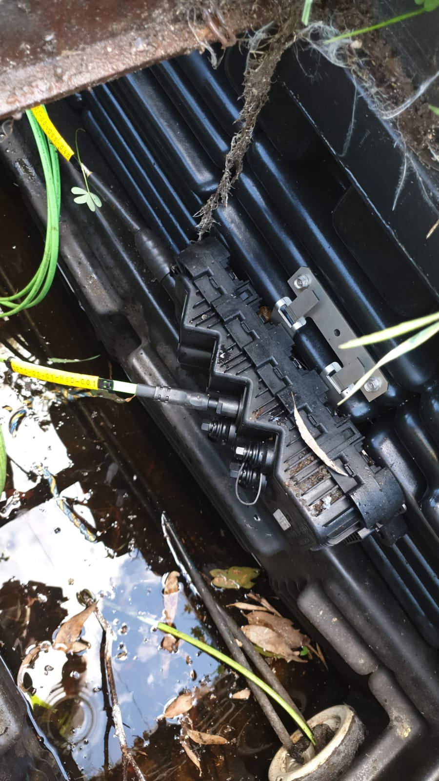
Sealed NBN FJLOpen NBN FJLReassembled NBN FJLFJL in situ in pitNeat open FJL
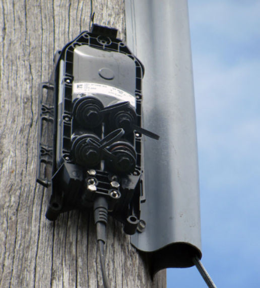
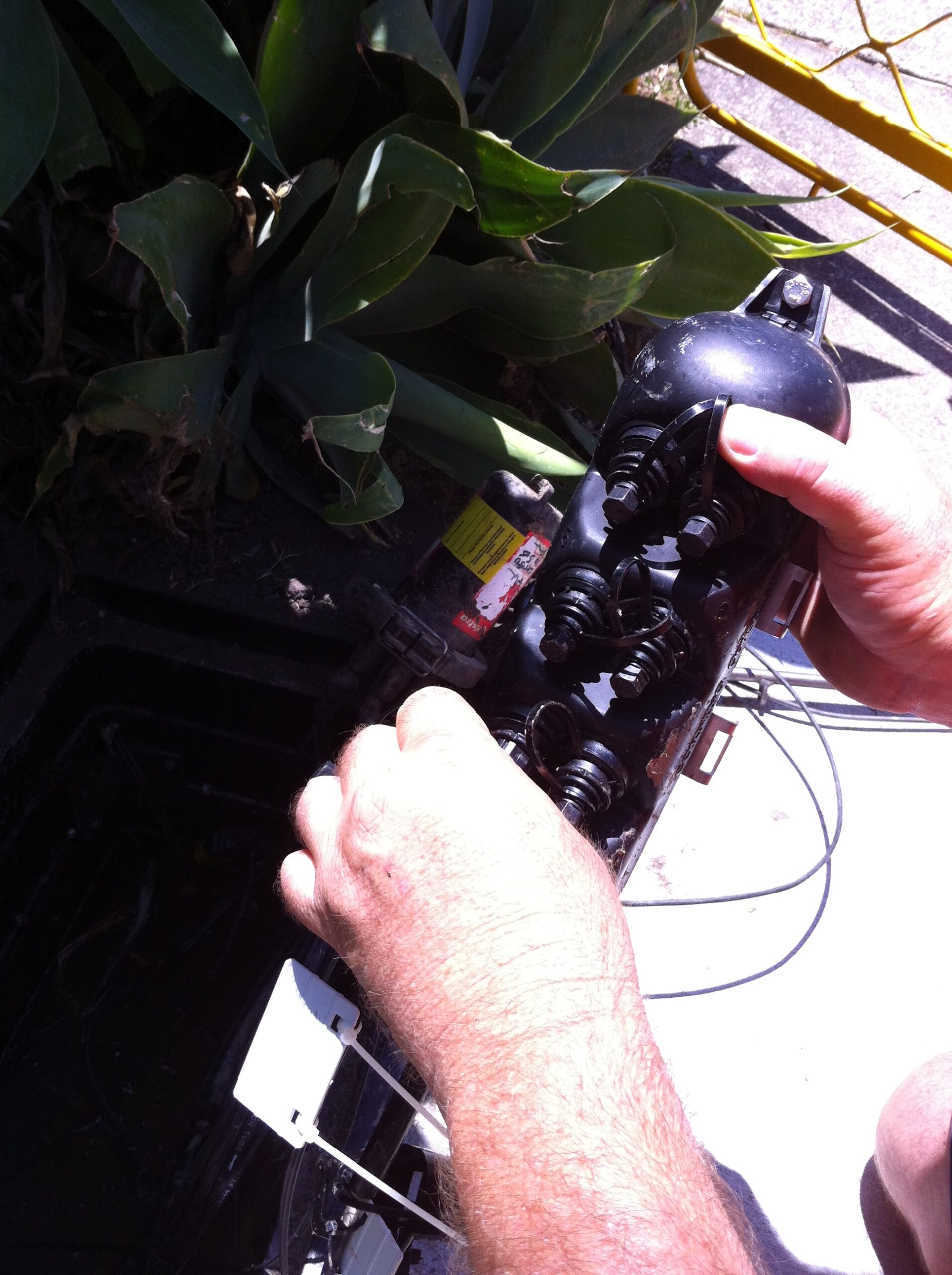
The splitters, referred to as “Multiports” or “SMPs” are Corning’s OptiSheath MultiPort Terminals, and they’re designed and laid out in such a way that the tech can activate a service, without needing to use a fusion splicer.
Due to the difficulty/cost in splicing fibre in pits for a service activation, NBNco opted to go from the FJL to the SMPs, where a field tech can just screw in a weatherproof fibre connector lead in to the customer’s premises.
During installation / activation callouts, the tech is assigned an SMP in the pit near the customer’s house, and a port on it. This in turn goes to the FJL and onto FDH cabinet as we just covered, but that patching/splicing for that is already done, so the tech doesn’t need to worry about that.
SMP in pitCorning OptiSheath Multiport SplitterSMP in a pit
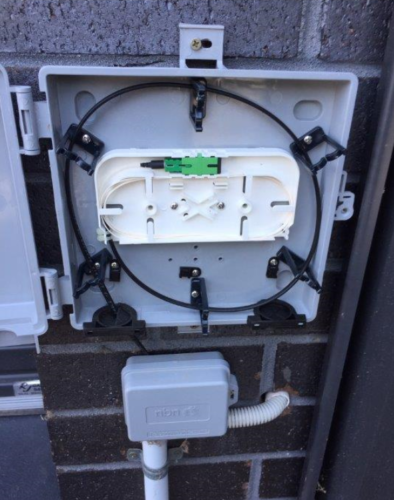
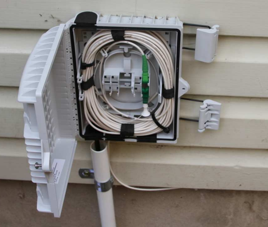
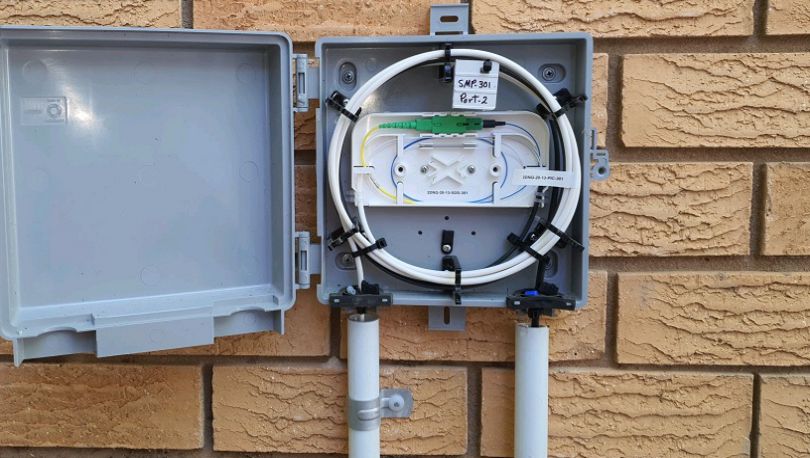
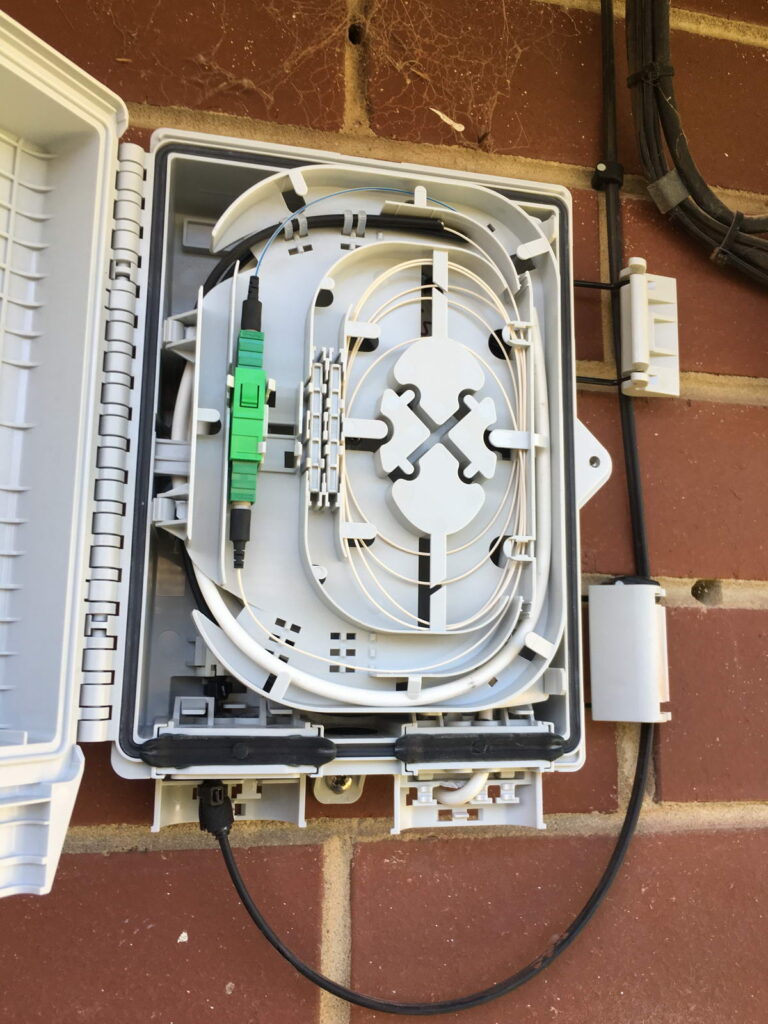
The tech just plugs in a pre-terminated lead in cable with a weatherproof fibre end, and screws it into the allocated port on the SMP, then hauls the other end of the lead in cable to the Premises Connection Device (Made by Madison or Tyco), located on the wall of the customer’s house.
TC000006252
The customer end of the lead in cable may be a pre terminated SC connector, or may get mechanically spliced onto a premade SC pigtail. In either case, they both terminate onto an SC male connector, which goes into an SC-SC female coupler inside the PCD.
Next is the customer’s internal wiring, again, preterm cable is used, to run between the PCD and the First Fibre Wall Outlet inside the house. This preterm cable join the lead in cable inside the PCD on the SC-SC female coupler, to join to the lead in.
Inside the house we have the “Network Termination Device” (NTD), which is a GPON ONT, is where the fibre from the street terminates and is turned into an Ethernet handoff to the customer. NBN has been through a few models of NTD, but the majority support 2x ATA ports for analog phones, and the option for an external battery backup unit to keep the device powered if mains power is lost.
Phew! That’s what I’ve been able to piece together from publicly available documentation, some of this may be out of date, and I can see there’s been several revisions to the LFN / DFN architectures over the years, if there’s anything I have incorrect here, please let me know!
A few years ago, I was out with a friend (who knows telecom history like no one else) who pointed at a patch of grass and some concrete and said “There’s an underground exchange under there”.
Being the telecommunications nerd that I am, I had a lot of follow up questions, and a very strong desire to see inside, but first, I’m going to bore you with some history.
I’ve written about RIMs – Remote Integrated Multiplexers before, but here’s the summary:
In the early ’90s, Australia was growing. Areas that had been agricultural or farmland were now being converted into housing estates and industrial parks, and they all wanted phone lines. While the planners at Telecom Australia had generally been able to cater for growth, suddenly plonking 400 homes in what once was a paddock presented a problem.
There were traditional ways to solve this of course; expanding the capacity at the exchange in the nearest town, trenching larger conduits, running 600 pair cables from the exchange to the housing estate, and distributing this around the estate, but this was the go-go-nineties, and Alcatel had a solution, the Remote Integrated Multiplexer, or RIM.
A RIM is essentially a stack of line cards in a cabinet by the side of the road, typically fed by one or more E1 circuits. Now Telecom Australia didn’t need to upgrade exchanges, trench new conduits or lay vast quantities of costly copper – Instead they could meet this demand with a green cabinet on the nature strip.
This was a practical and quick solution to increase capacity in these areas, and this actually worked quite well; RIMs served many Australian housing estates until the copper switch off, many having been upgraded with “top-hats” to provide DSLAM services for these subscribers as well, or CMUX being the evolved version. There’s still RIMs that are alive in the CAN today, in areas serviced by NBN’s Fixed Wireless product, it’s not uncommon to see them still whirring away.
A typical RIM cabinet
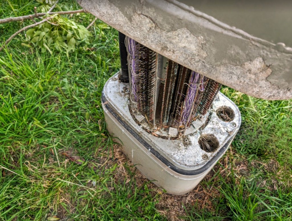
But in some areas planning engineers realised some locations may not be suitable for a big green cabinet, for this they developed the “Underground CAN Equipment Housing” (UCEH). Designed as a solution for sensitive areas or locations where above ground housing of RIMs would not be suitable – which translated to areas council would not them put their big green boxes on their nature strips.
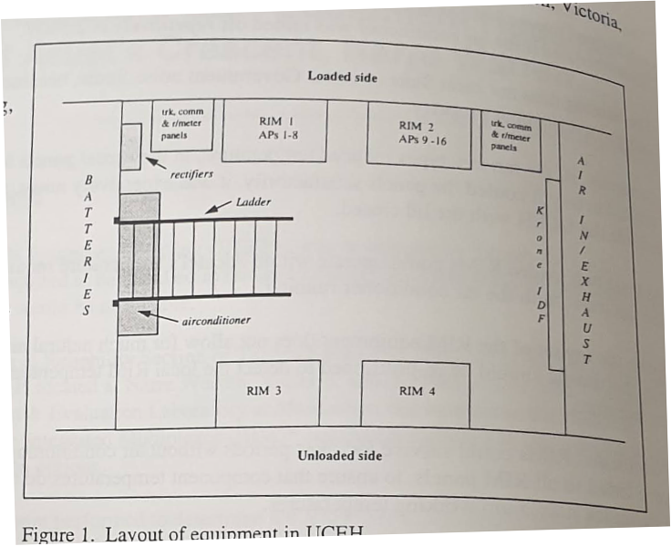
So in Narre Warren in Melbourne’s outer suburbs Telecom Research Labs staff built the first underground bunker to house the exchange equipment, line cards, a distribution frame and batteries – a scaled down exchange capable of serving 480 lines, built underground.
Naturally, an underground enclosure faced some issues, cooling and humidity being the big two.
The AC systems used to address this were kind of clunky, and while the underground exchanges were not as visually noisy as a street cabinet, they were audibly noisy, to the point you probably wouldn’t want to live next to one.
Sadly, for underground exchange enthusiasts such as myself, by 1996, OH&S classified these spaces as “Confined Spaces”, which made accessing them onerous, and it was decided that new facilities like this one would only be dug if there were no other options.
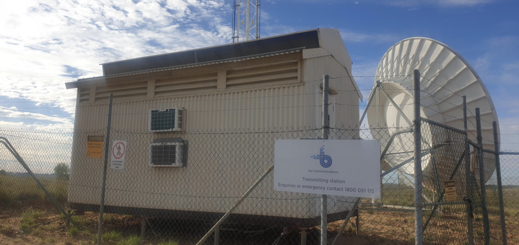
This wasn’t Telecom Australia’s first foray into underground equipment shelters, some of the Microwave sites in the desert built by telecom put the active equipment in underground enclosures covered over by a sea freight container with all the passive gear.
Some of these sites still exist today, and I was lucky enough to see inside one, and let’s face it, if you’ve read this far you want to see what it looks like!
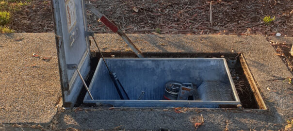
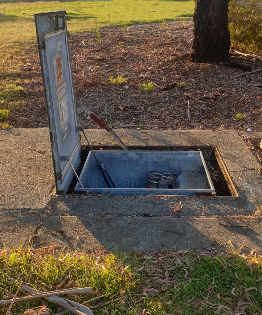
A large steel plate sunk into a concrete plinth doesn’t give away what sits below it.
A gentle pull and the door lifts open with a satisfying “woosh” – assisted by hydraulics that still seem to be working.
The power to the site has clearly been off for some time, but the sealed underground exchange is in surprisingly good condition, except for the musky smell of old electronics, which to be honest goes for any network site.
There’s an exhaust fan with a vent hose that hogs a good chunk of the ladder space, which feels very much like an afterthought.
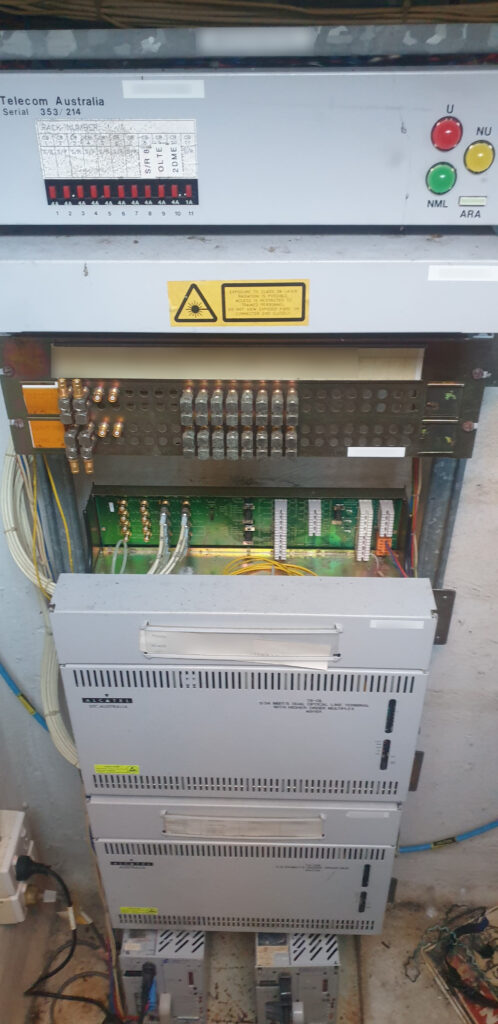
Inside is pretty dark, to be expected I guess what with being underground, and not powered.
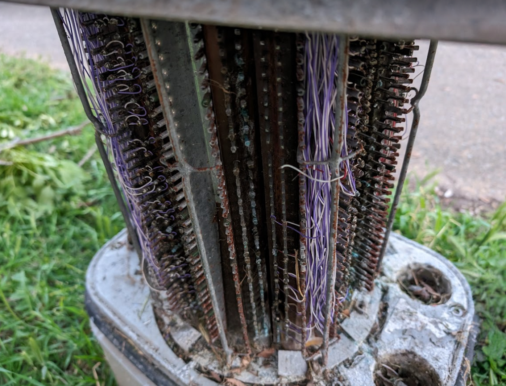
Inside is the power system (well, the rectifiers – the batteries were housed in a pit at the end of the UECH entrance hatch, so inside there are no batteries), a distribution frame (MDF / IDF), and the Alcatel cabinets that are the heart of the RIM.
From the log books it appeared no one had accessed this in a very long time, but no water had leaked in, and all the equipment was still there, albeit powered off.
I’ve no idea how many time capsules like this still exist in the network today, but keep your eyes peeled and you might just spot one yourself!
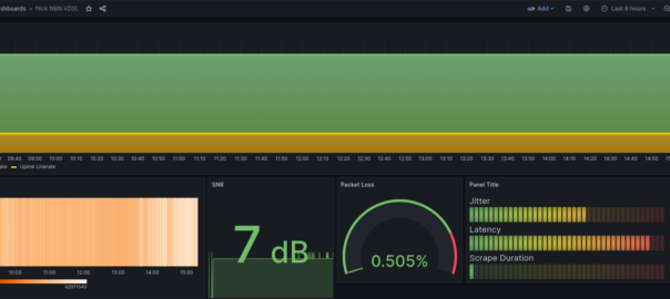
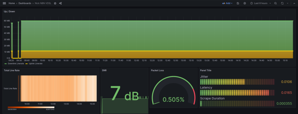
I am connected on a VDSL line, not by choice, but here we are. DSL is many things, but consistent it not one of them, so I thought it’d be interesting to graph out the SNR and the line rate of the connection.
This is an NBN FTTN circuit, I run Mikrotiks for the routing, but I have a Draytek Vigor 130 that acts as a dumb modem and connects to the Tik.
Draytek exposes this info via SNMP, but the OIDs / MIBs are not part of the standard Prometheus snmp_exporter, so I’ve added them into snmp_exporter.yaml and restarted the snmp_exporter service.
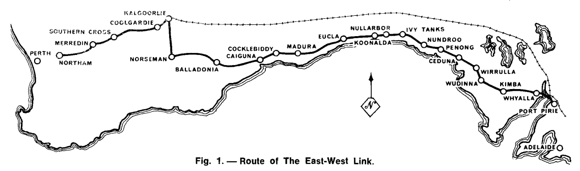
On July 9, 1970 a $10 million dollar program to link Australia from East to West via Microwave was officially opened. Spanning over 2,400 kilometres, it connected Northam (to the east of Perth) to Port Pirie (north of Adelaide) and thus connected the automated telephone networks of Australia’s Eastern States and Western States together, to enable users to dial each other and share video live, across the country, for the first time.
In 1877, long before road and rail lines, the first telegraph line – a single iron wire, was spanned across the Nullabor to link Australia’s Eastern states with Western Australia.
By 1930 an open-wire voice link had been established between the two sides of the continent. This was open-wire circuit was upgraded a rebuilt several times, to finally top out at 140 channels, but by the 1960s Australian Post Office (APO) engineers knew a higher bandwidth (broadband carrier) system was required if ever Standard Trunk Dialling (STD) was to be implemented so someone in Perth could dial someone in Sydney without going via an operator.
A few years earlier Melbourne and Sydney were linked via a 600 kilometre long coaxial cable route, so API engineers spent months in the Nullarbor desert surveying the soil conditions and came to the conclusion that a coaxial cable (like the recently opened Melbourne to Sydney Coaxial cable) was possible, but would be very difficult to achieve.
Instead, in 1966, Alan Hume, the Postmaster-General, announced that the decision had been made to construct a network of Microwave relay stations to span from South Australia to Western Australia.
In the 1930s microwave communications had spanned the English channel, by 1951 AT&T’s Long Lines microwave network had opened, spanning the continental United States. So by the 1960’s Microwave transmission networks were commonplace throughout Europe and the US and was thought to be fairly well understood.
But soon APO engineers soon realised that the unique terrain of the desert and the weather conditions of the Nullabor, had significant impacts on the transmission of Radio Waves. Again Research Labs staff went back to spend months in the desert measuring signal strength between test sites to better understand how the harsh desert environment would impact the transmission in order to overcome these impediments.
The length of the link was one of the longest ever attempted, longer than the distance from London to Moscow,
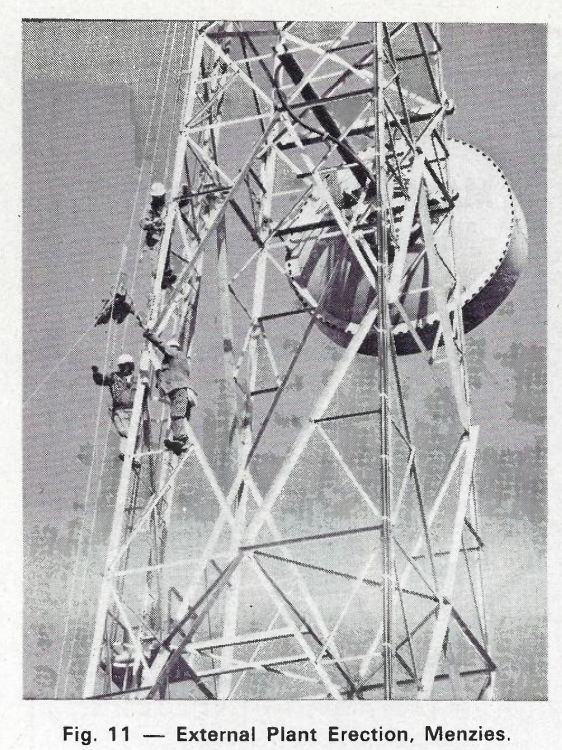
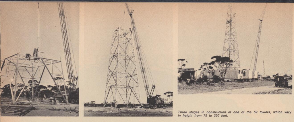
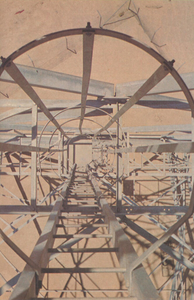
In the end it was decided that 59 towers with heights from 22 meters to 76 meters were to be built, topped off with 3.6m tall microwave dishes for relaying the messages between towers.
The towers themselves were to be built in a zig-zag pattern, to prevent overshooting microwave signals from interfering with signals for the next station in the chain.
Due to the remote nature of the repeater sites, for 43 of the 59 repeater sites had to be fully self sufficient in terms of power.
Initial planning saw the power requirements of the repeater sites to be limited to 500 watts, APO engineers looked at the available wind patterns and determined that combined with batteries, wind generators could keep these sites online year round, without the need for additional power sources. Unfortunately this 500 watt power consumption target quickly tripled, and diesel generators were added to make up any shortfall on calm days.
The addition of the Diesel gensets did not in any way reduce the need to conserve power – the more Diesel consumed, the more trips across the desert to refuel the diesel generators would be required, so the constant need to keep power to a minimum was one of the key restraints in the project.
The designs of these huts were reused after the project for extreme temperature equipment housings, including one reused by Broadcast Australia seen in Marble Barr – The hottest town in Australia.
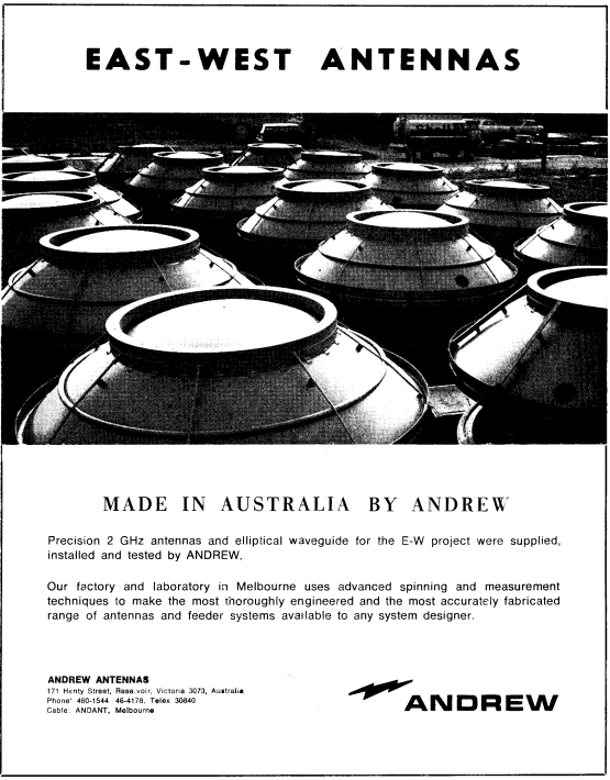
Active cooling systems (Like Air Conditioning) were out of the question due to being too power hungry. APO engineers knew that the more efficient equipment they could use, the less heat they would produce, and the more efficient the system would be, so solid state (transistorised devices) were selected for the 2Ghz transmission equipment, instead of valves which would have been more power-hungry and produced more heat.
The reduced power requirement of the fully transistorized radio equipment meant that wind-supplied driven generators could provide satisfactory amounts of power provided that the wind characteristics of the site were suitable.
THE TELECOMMUNICATION JOURNAL OF AUSTRALIA / Volume 21 / Issue 21 / February 1971
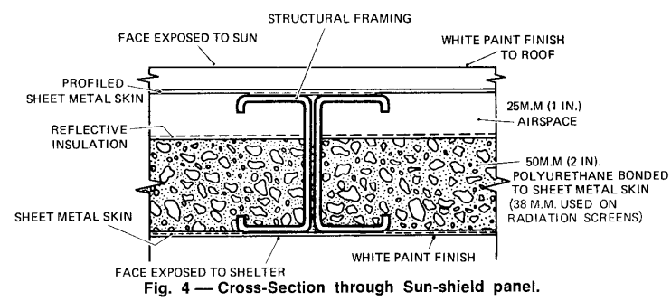
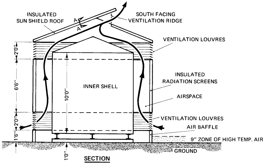
So forced to use passive cooling methods, the engineers on the project designed the repeater huts to cleverly utilize ventilation and the orientation of the huts to keep them as cool as possible.
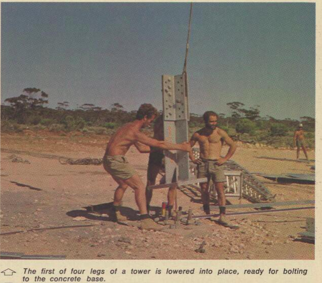
Construction was rough, but in just under 2 years the teams had constructed all 59 towers and the associated equipment huts to span the desert.
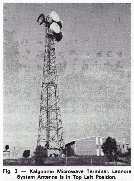
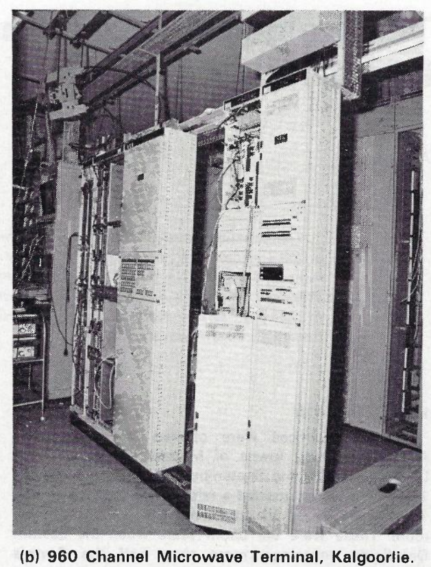
Average time to construct a tower was 6 daysMenzies, built in the 1980s as an additional spurTower in Kalgoorlie
When the system first opened for service in July 1970, live TV programs could be simulcast on both sides of the country, for the first time, and someone in Perth could pick up the phone and call someone in Melbourne directly (previously this would have gone through an operator).
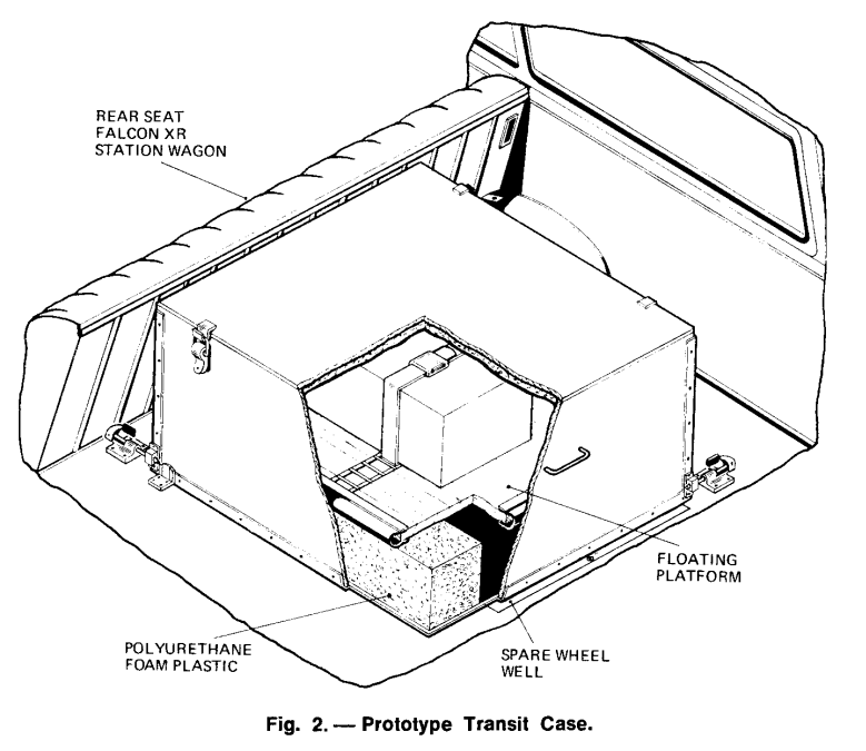
PMG Engineers designed a case to transport the fragile equipment spares – That resided in the back of a Falcon XR Station Wagon
The system offered 1+1 redundancy, and capacity for 600 circuits, split across up to 6 radio bearers, and a bearer could be dedicated at times to support TV transmissions, carried on 5 watt (2 watt when modulated) carriers, operating at 1.9 to 2.3Ghz.
By linking the two sides of Australia, Telecom opened up the ability to have a single time source distributed across the country, the station in Lyndhurst in Victoria, created the 100 “microseconds” signal generated by a VNG, that was carrier across the link.
Looking down one of the towers
Unlike AT&T’s Long Lines network, which lasted until after MCI, deregulation and the breakup off the Bell System, the East-West link didn’t last all that long.
By 1981, Telecom Australia (No longer APO) had installed their first experimental optic fibre cable between Clayton and Springvale, and fibre quickly became the preferred method for broadband carrier circuits between exchanges.
By 1987, Melbourne and Sydney were linked by fibre, and the benefits of fibre were starting to be seen more broadly, and by 1989, just under 20 years since the original East-West Microwave system opened, Telecom Australia completed a 2373 kilometre long / 14 fibre cable from Perth to Adelaide, and Optus followed in 1993.
This effectively made the microwave system redundant. Fibre provided a higher bandwidth, more reliable service, that was far cheaper to operate due to decreased power requirements. And so piece by piece microwave hops were replaced with fibre optic cables.
I’m not clear on which was the last link to be switched off (If you do know please leave a comment or drop me a message), but eventually at some point in the late 1980s or early 1990s, the system was decommissioned.
Many of the towers still stand today and carry microwave equipment on them, but it is a far cry from what was installed in the late 1960s.
I had a question recently on LinkedIn regarding how to preference Voice over WiFi traffic so that a network engineer operating the WiFi network can ensure the best quality of experience for Voice over WiFi.
Voice over WiFi is underpinned by the ePDG – Evolved Packet Data Gateway (this is a fancy IPsec tunnel we authenticate to using the SIM to drop our traffic into the P-CSCF over an unsecured connection). To someone operating a WiFi network, the question is how do we prioritise the traffic to the ePDGs and profile it?
ePDGs can be easily discovered through a simple DNS lookup, once you know the Mobile Network Code and Mobile Country code of the operators you want to prioritise, you can find the IPs really easily.
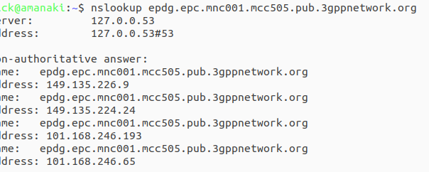
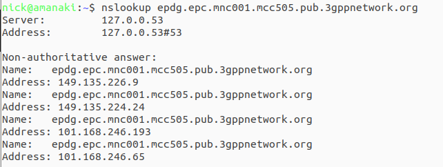
ePDG addresses take the form epdg.epc.mncXXX.mccYYY.pub.3gppnetwork.org so let’s look at finding the IPs for each of these for the operators in a country:
The first step is nailing down the mobile network code and mobile country codes of the operators you want to target, Wikipedia is a great source for this information. Here in Australia we have the Mobile Country Code 505 and the big 3 operators all support Voice over WiFi, so let’s look at how we’d find the IPs for each. Telstra has mobile network code (MNC) 01, in 3GPP DNS we always pad network codes to 3 digits, so that’ll be 001, and the mobile country code (MCC) for Australia is 505. So to find the IPs for Telstra we’d run an nslookup for epdg.epc.mnc001.mcc505.pub.3gppnetwork.org – The list of IPs that are returned, are the IPs you’ll see Voice over WiFi traffic going to, and the IPs you should provide higher priority to:
The same rules apply in other countries, you’d just need to update the MNC/MCC to match the operators in your country, do an nslookup and prioritise those IPs.
Generally these IPs are pretty static, but there will need to be a certain level of maintenance required to keep this list up to date by rechecking.
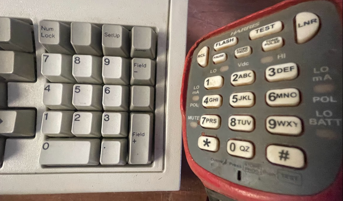
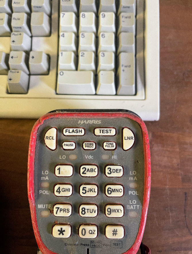
If you’re typing on a full size keyboard there’s a good chance that to your right, there’s a number pad.
The number 5 is in the middle – That’s to be expected, but is 1 in the top left or bottom left?
Being derived from an adding machine keypad, the number pad on a keyboard has a 1 will be in the bottom left, however in the 1950s when telephone keypads were being introduced, only folks who worked in accounting had adding machines.
So when it came time to work out the best layout, the result we have today was a determined through a stack of research and testing by Human Factors Engineering Department of Bell Labs who studied the most efficient layout of keys, and tested focus groups to find the layout that provided the best level of speed and accuracy.
That landed with the 1 in the top left, and that’s what we still have today.
Oddly ATM and Card terminals opted to use the telephone layout, rather than the adding machine layout, while number pads use the adding machine layout.
Note: All information contained here is sourced from: Photos provided by NBNco’s press pages, Googling part numbers from these photos, and public costing information.
This post covers the specifics and capabilities of NBNco’s FTTN solution, and is the result of some internet sleuthing.
If some of the info in here is now out of date, I’d love to know, let me know in the comments or drop me an email and I’ll update it.
FTTN in Numbers
A total of 24,544 nodes have been deployed upon completion of roll out. Each node is provisioned with 384 subscriber ports.
The hardware has 10Gbps shared between the 384 subscriber lines, equating to 208Mbps per subscriber.
Construction costs were $2.311 billion and hardware costs were $1.513 billion,
For the hardware this equates to $61,644 per node or $160 per subscriber line connected (each node is provisioned with 384 ports)
Full cost for node including hardware, construction and provisioning is $244,150 per node, which is $635 per port.
To operate the FTTN infrastructure costs $709 million per year (Made up of costs such as power, equipment servicing and spares). This equates to $28k per node per annum, or $75 per subscriber. (This does not take into account other costs such as access to the copper, transmission network, etc, just the costs to have the unit powered on the footpath.)
Overview
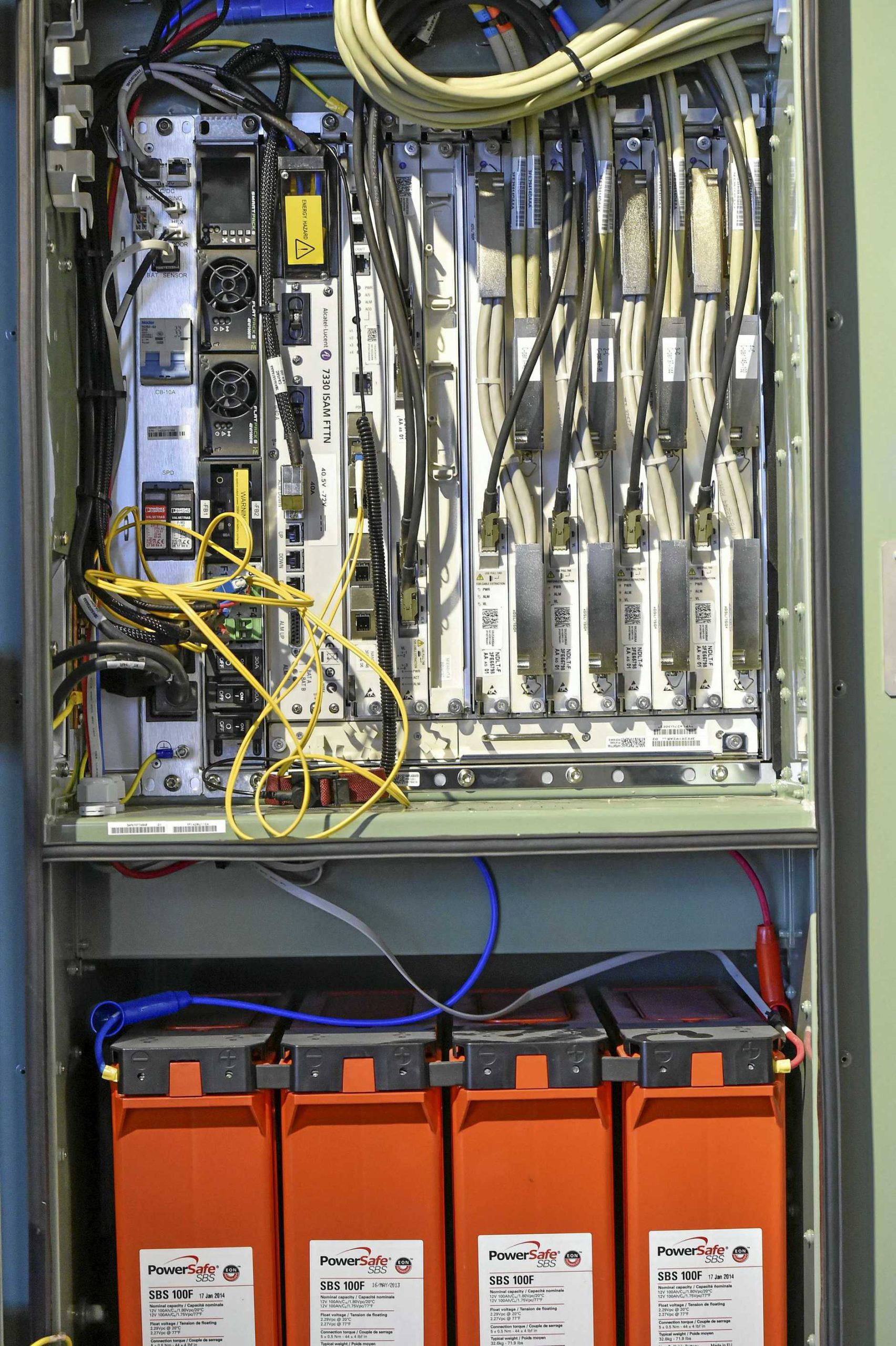
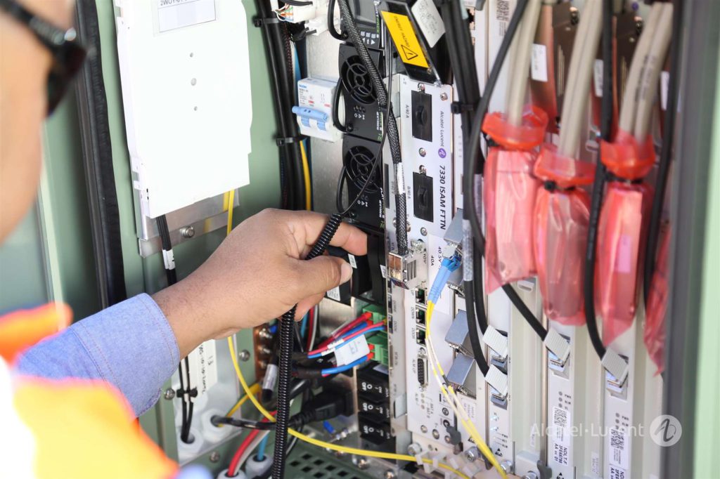
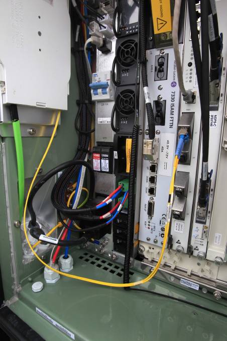
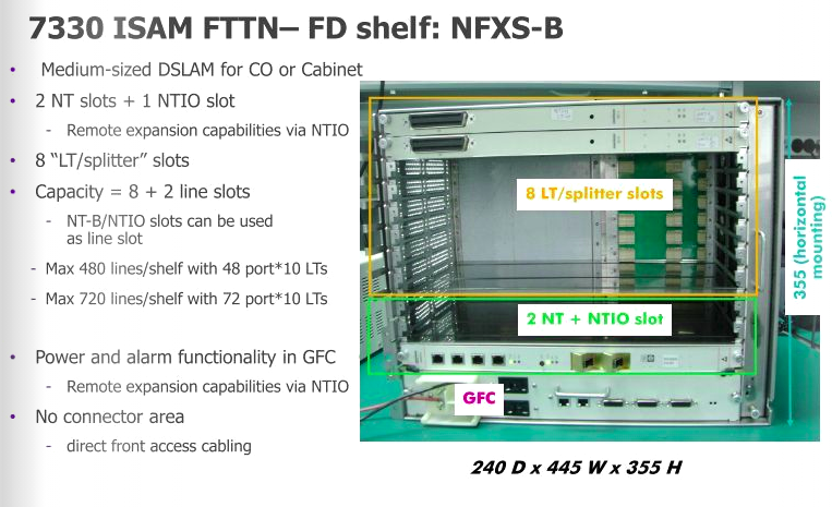
Inside the FTTN cabinets is a Alcatel Lucent (now Nokia) ISAM 7330 cabinet mounted on it’s side,
On the inside left of the door is a optic fibre tray where the transmission links come into the cabinet,
On the extreme left is a custom panel. It contains I/Os that are fed to the 7330, such as door open sensor, battery monitoring, AC power in, SPD and breaker.
Connection to subscriber lines happens on a frame at the end of the cabinet.
Alcatel Lucent ISAM 7330 FTTN
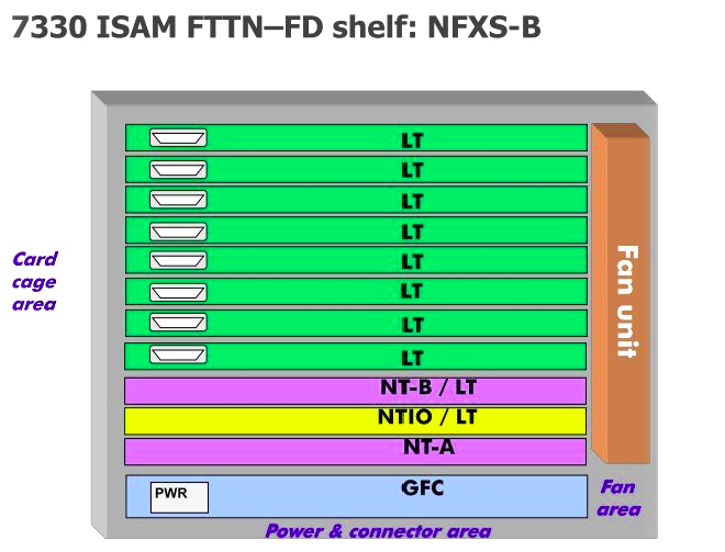
NBN co’s nodes are made up of Alcatel Lucent (Now Nokia) ISAM (Intelligent Services Access Manager) 7330 FTTN rack mounted it’s side.
Slot
Type
Function
1
GFC (General Facilities Card)
Power and alarm management
2
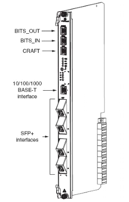
NT Slot (NANT-E Card)
Main processing and transmission
3
NTIO Slot (NDPS-C Card)
VDSL vectoring number-crunching
4
NT Slot (Free)
Optional (Unused) backup Main processing and transmission
5-12
LT (NDLT-F)
48 Port VDSL Subscriber DSLAM Interfaces
Slot numbering is just counting L to R, ALU documentation has different numbering
First up is the GFC (General Facilities Card) which handles alarm input / output, and power distribution. This connects to the custom IO panel on the far left of the cabinet, meaning the on-board IO ports aren’t all populated as it’s handled by the IO panel. (More on that later)
Next up is the first NT slot, there are two on the 7330, but in NBN’s case, only one is used; the second can be used for redundancy if one of the cards were to fail, but it seems this option has not been selected. In the first and only populated NT slot is an NANT-E Card (Combined NT Unit E) which handles transmission and main processing.
All the ISAM NANT cards support support RIPv2! But only the NANT-E card also supports BGP – Interestingly they don’t have BGP on all the NANT cards?
To the right of that is the NTIO slot, which has a NDPS-C card, which handles the vector processing for VDSL.
Brief overview of Vectoring: By adding vectoring to DSL signals allows noise on subscriber loops to be modeled, and then cancelled out with an integrated anti-phase signal matching that of the noise.
The vectoring in VDSL relies on pretty complex number crunching as the DSLAM has to constantly process the vectoring coefficients which are different for each line and can change based on the conditions of the subscriber loop etc. To do this the NDPS-C has two roles; The NDPS-C’s Vectoring Control Entity performs non-real time calculations of vectoring coefficients and handles joining and leaving of vectored VDSL2 lines. While the NDPS-C’s Vectoring Processor performs the real time matrix calculations based on crosstalk correction samples for the VDSL symbols collected from the subscriber lines. The NDPS-C has a Twinax connection to every second LT Card.
After the NTIO slot is the unused NT slot.
Finally we have the 8 LT slots for line cards, which for FTTN is using the NDLT-F are 48 port line cards.
The 8 card slots allows 384 subscriber lines per node.
These are the cards which the actual subscriber lines ultimately connect to. With 10Gbps available from the NT to the LTs, means each LT card with 48 subs so 208 Mbps per subscriber max theoretical throughput.
POTS overlay is supported, this allowed VF services coexisted on the same copper during the rollout. M / X pairs are no longer added inline on new connections. (More on that on cabling).
Power & Environment
The 7330 has a 40 amp draw at -48v would mean the unit consumes 1920w
The -48v supply is provided by 2x Eltek Flatpack2 rectifiers, each providing 1Kw each.
These can be configured to provide 1Kw with redundancy to protect against the failure of one of the Flatpack2 units, or 2Kw with no redundancy, which is what is used here.
On the extreme left is a custom panel. It contains alarm I/Os that are fed to the 7330, such as door open sensor, battery monitoring, etc.
It also is the input for AC power in, surge protection device and breakers.
I did have some additional information on the batteries used and the power calculations, however NBNco’s security team have asked that this be removed.
Cabling
Incoming transmission fiber comes in on NBNco’s green ribbon fibre, which terminates on a break out tray on the left hand side wall of the cabinet. Spliced inside the tray is a duplex LC pigtail for connecting the SMF to the 7330. I don’t have the specifics on the optics used.
Subscriber lines come in via an IDC distribution frame (Quante IDS) on the right hand side end of the cabinet, accessed through a seperate door.
This frame is referred to as the CCF – Cross Connect Frame.
There are two sets of blocks on the CCF, termination of ‘X’ and ‘C’ Pairs.
‘X’ Pairs are the VF Pairs (PSTN lines) connecting to the pillar where they are jumpered back to the ‘M’ pairs back to the serving exchange,
‘C’ Pairs are the pairs containing combined VDSL & VF services to to the pillar where they are jumpered to the ‘O’ pairs which run out to the customer’s premises,
On the rare occasions I’m not tied to my desk, I’m out for a long run along some back roads somewhere.
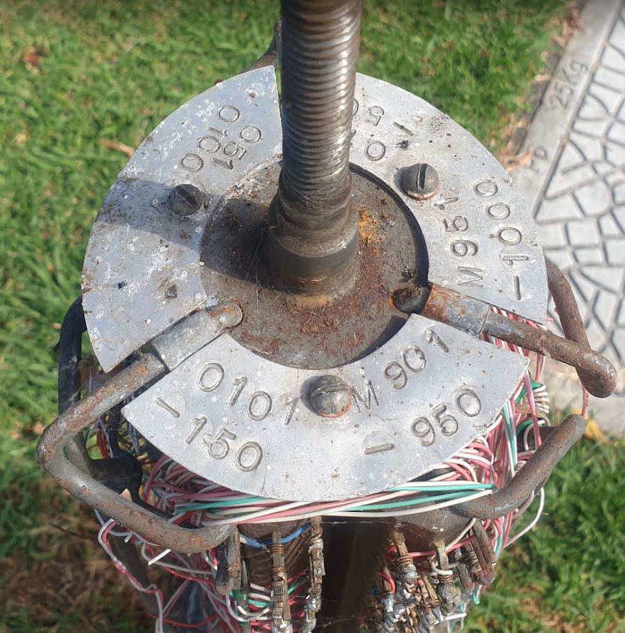
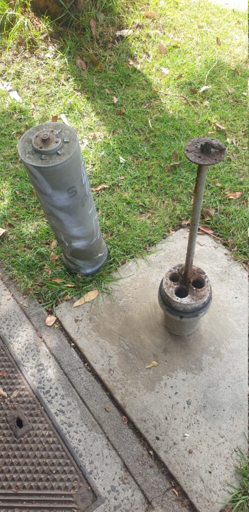
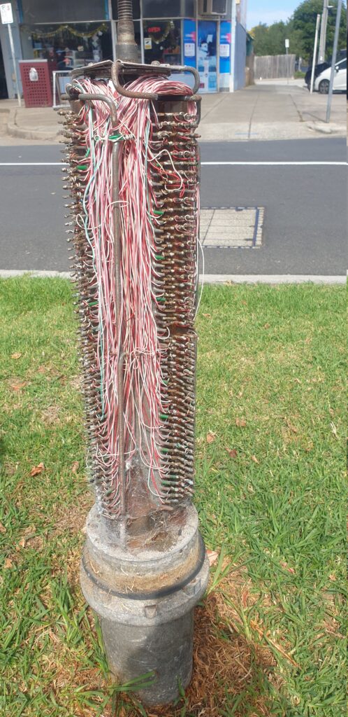
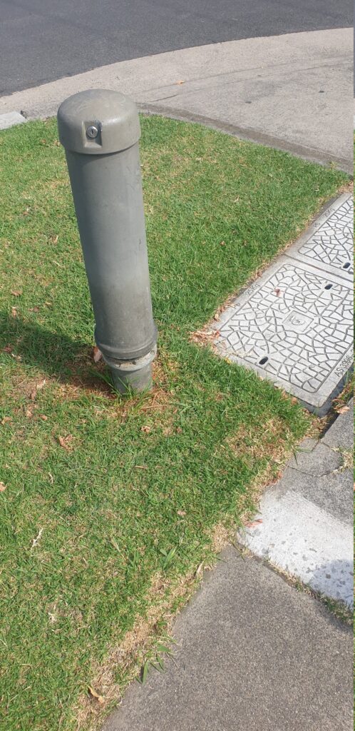
Every now and then I come across these tiny telecom pillars for cross-connection (and don’t shoot at them) – I mostly find them around the edges of distribution areas. I had some recollection that these were originally for trunk lines between exchanges (maybe there was some truth to this?), but some digging in old docs show these were just for interconnecting main or branch cables with distribution cables, in areas where the 600 and 1200 pair pillars / cabinets would be overkill.
They’re built like the 900/1800 pair cabinets, but just scaled down versions, supporting 1x 100 pair main cable, 1x 100 pair distribution cables and 2x 50 pair distribution cables.
It seems like these were largely decomed when NBN took over, leaving most with a big X sprayed on them.
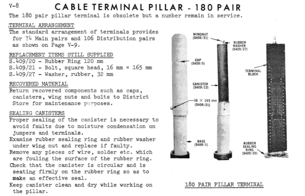
While I was looking through the docs I also found reference to a 180 pair pillar, which looked very similar, but I’ve yet to see any of them left in the wild. Better keep running ’till I find one!
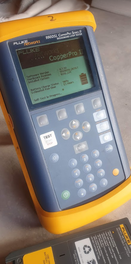
Arguably, the most capable (toolbox-carryable) test set out there is the Fluke 990 CopperPro, combined TDR, Butt Set, Toner, RFL, Noise meter, etc, etc, it’s a really cool gizmo (And probably worthy of a blog post in itself someday).
Alas mine had stopped taking much of a charge, you’d plug it into the charger, and after 20 minutes of use, it’d report low power and shut down.
Sitting on the charger the Fluke would show the red charging light for about 20 minutes, then the charging light would turn off.
If I unplugged and replugged the charger I’d get red charging light for another few minutes, then turn off again.
Naively, I ruled it to be an issue with the battery (Which is close to 10 years old), and ordered a new one.
But with the new battery in hand, the same issue.
Stupidly, it turns out I was using a 15v charger, technically the unit supports a 15v charger, but it seems after a period, the internal voltage regulator overheats and shuts off, meaning the battery never got a good charge.
Swapping it with a 12v charger and I’m charging without issues.
But not before I ended up ordering a new battery, so now with the new battery I’m getting 15 hours of runtime out of a charge, and still squeezing 7 out of 8 year old battery it originally came with.
Dumb mistake but hopefully an easy fix for anyone with the same issue.
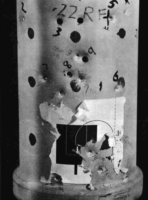
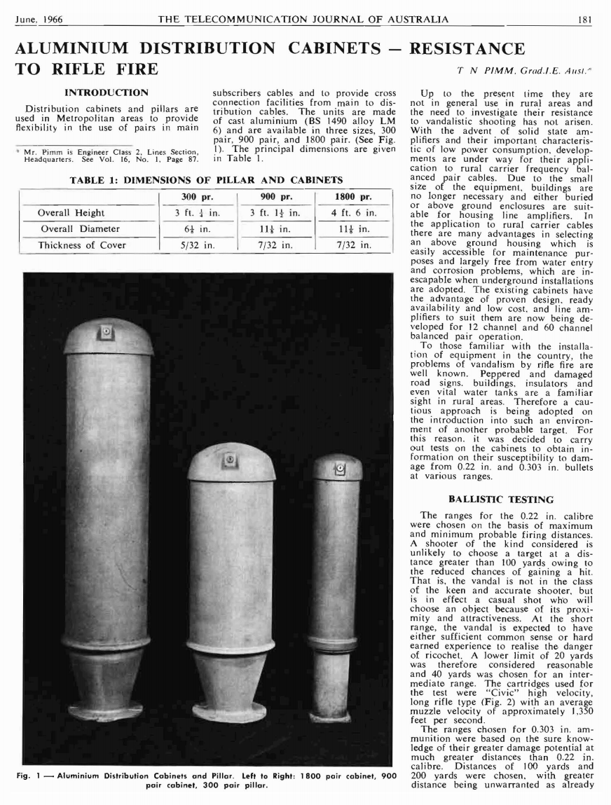
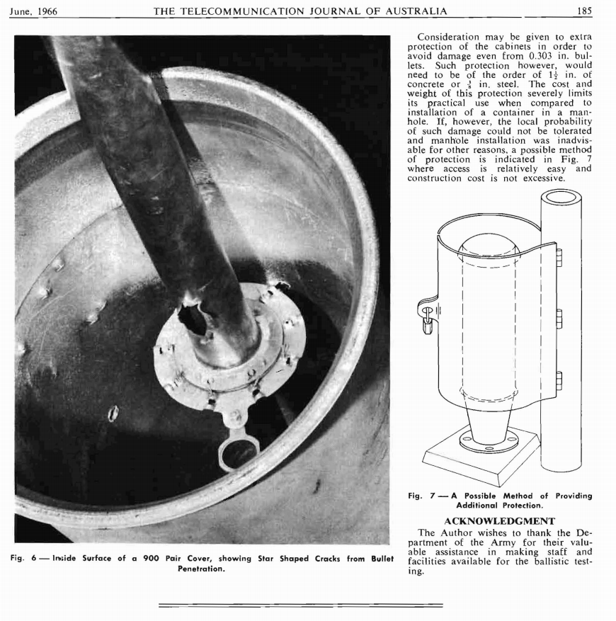
The 900 and 1800 pair telecom distribution pillars (aka cabinets) are still a familiar sight almost everywhere in Australia where copper networks are still used, however prior to the early 1970s they were only deployed in metropolitan areas, and apparently one of the concerns of deploying them in rural areas was that they’d be shot at.
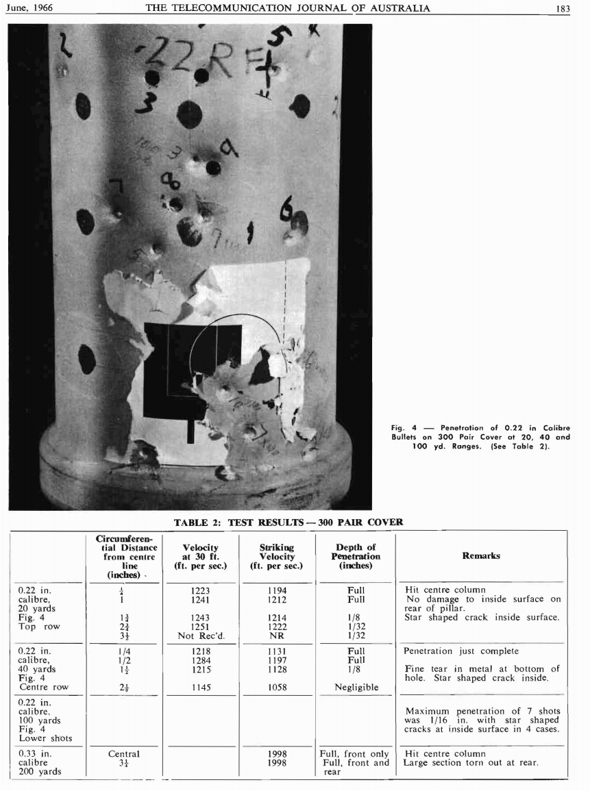
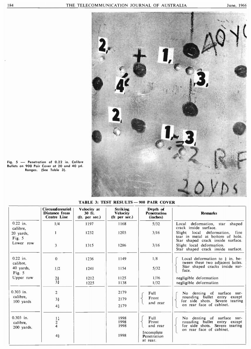
June 1966 issue of the Telecommunications Journal of Australia (TJA) has an article titled “Aluminum Distribution Cabinets – Resistance to Rifle Fire” is below, click to get the image full size.
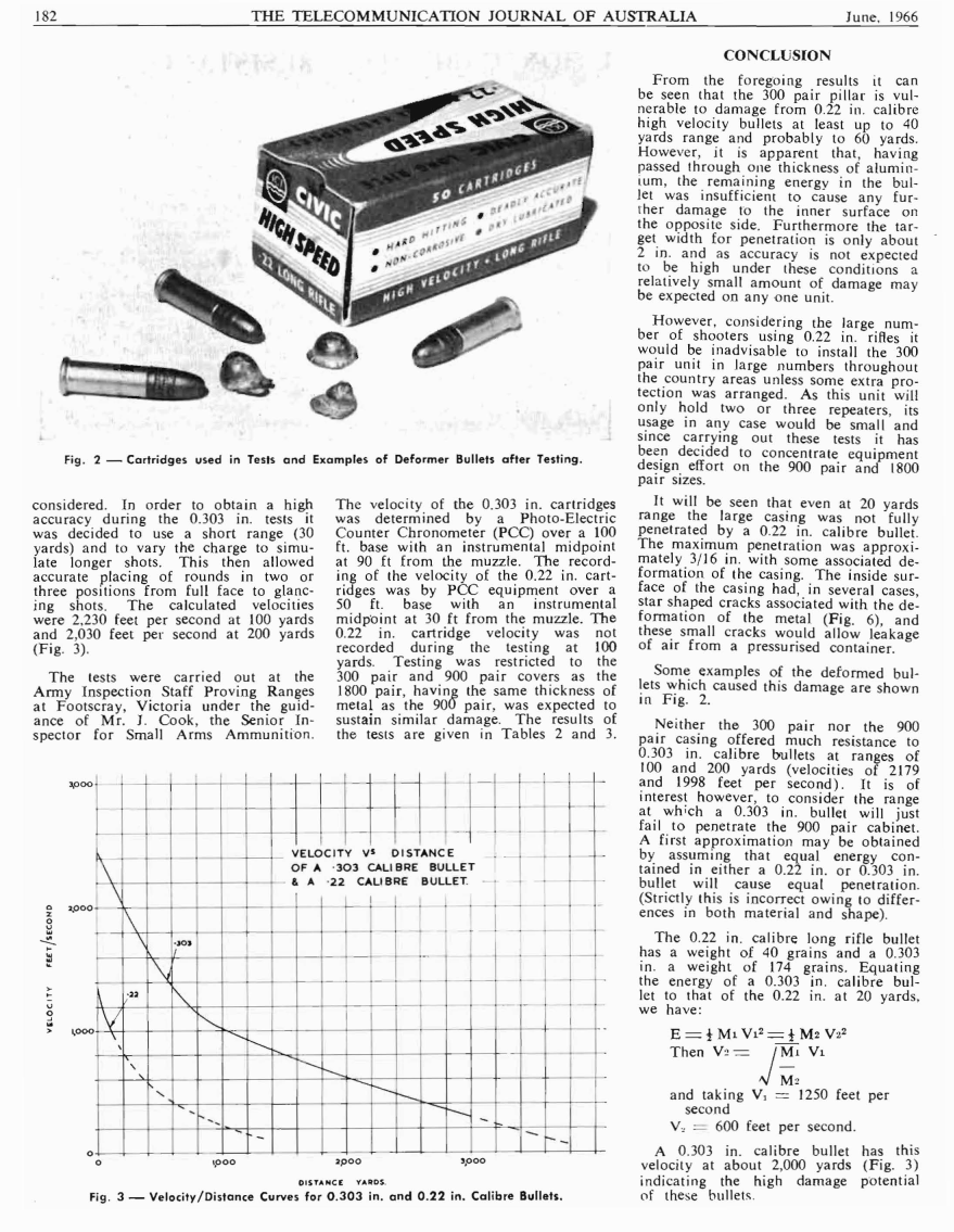
At the short range, the vandal is expected to have either sufficient common sense or hard earned experience to realise the danger of ricochet.
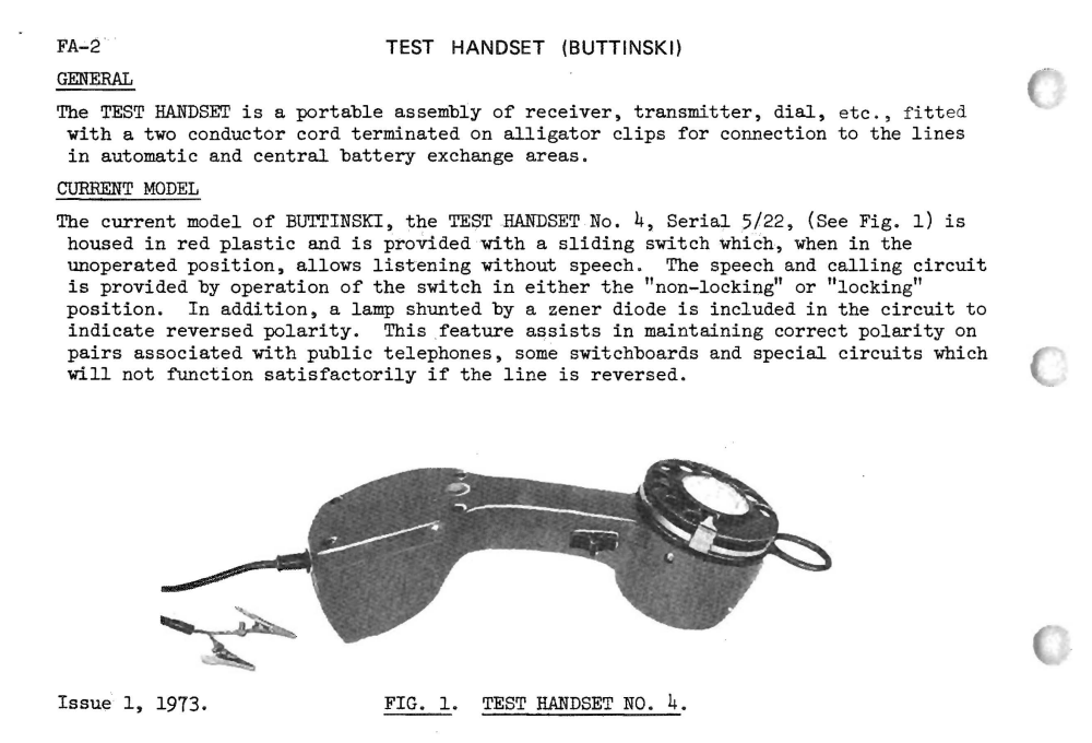
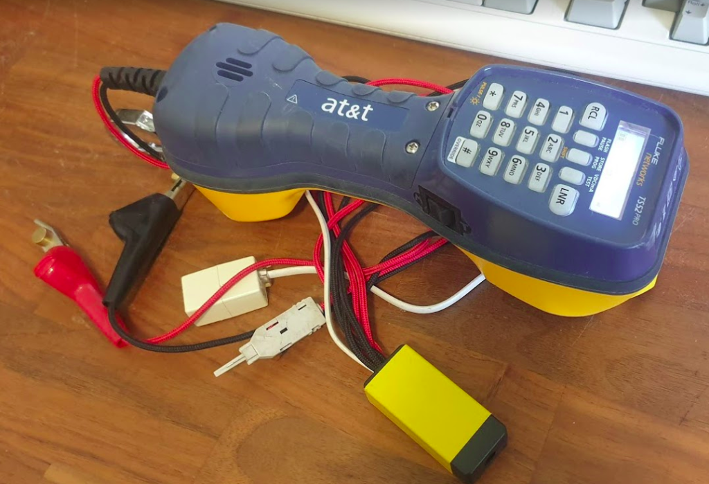
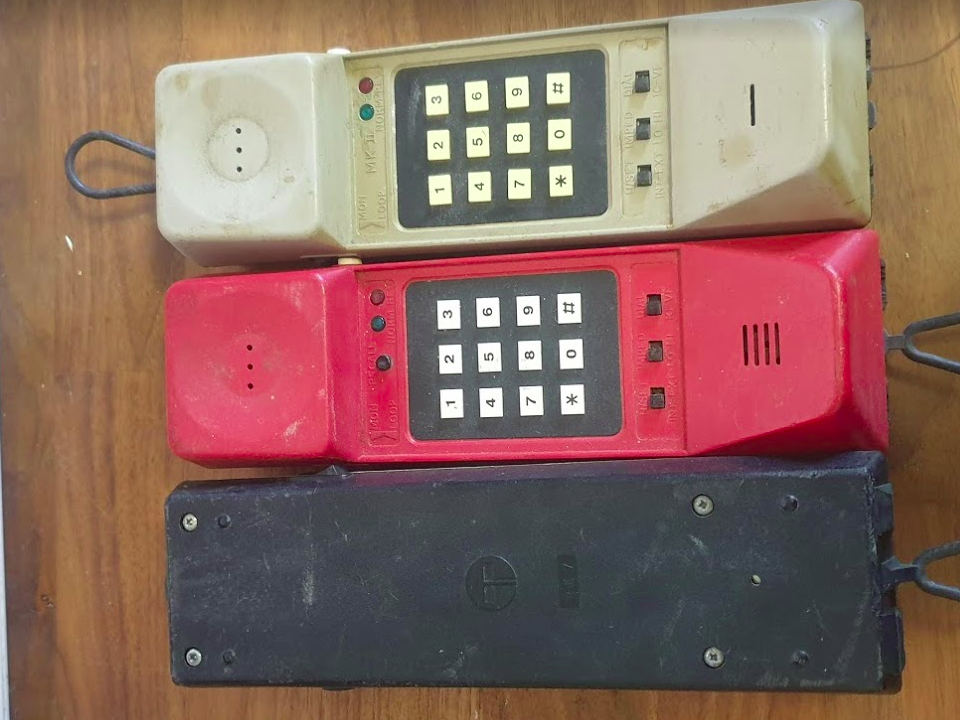
In other parts of the world it’s known as a telephone test set, lineman’s handset, test phone, etc, but to me it’s a butt / butt set / buttinski.
They’re essentially ruggedized, portable telephones, often with an ability to monitor a line without looping it / going off hook, and used by techs and lineys throughout phone networks everywhere.
I carry Fluke TS52 Pro in my toolbox, it’s got a built in voltmeter, waterproof, backlit display and lots of memory storage options.
It’s a really beautiful bit of kit, (only thing missing is a TDR which the next model up has) but I very rarely use it.
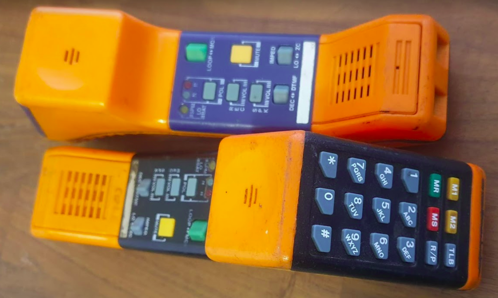
The butt set is in my mind the quintessential piece of test gear, and I’ve got a few from various time periods.
The Telecom Ruggabut was launched in 1994/1995 and was standard issue prior to privatization, and was designed in Australia for the Australian market,
As such it features some uniquely Australian features such as detection for 12kHz Subscriber Pulse Metering (used in Payphones), while the “TLB” Button is tone-loop-break, a 100ms pause in dialling,
Prior to the Ruggabutt there was the Versadial and Versadial Mk2. Lightweight, tough and with a handy RJ12 jack for testing subscriber handpieces, these were made in huge numbers, by PMG and then Telecom.
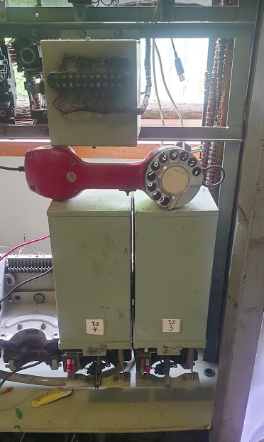
And as far back as my “collection” goes is the Australian Post Office (APO) Telephone Test Handset No. 4, which lives on the Step exchange in my office, and is a simple rotary dial plus speaker, mic, switch and Neon light to denote ringing.
Here’s the list of books I’ve got for the holiday period:
5G Core Networks: Powering Digitalization
A good technical overview of the 5GC architecture, covering the actual elements and their interfaces / reference points, without any talk of robotic surgery.
Clear Across Australia (A history of Telecommunications)
Ann Moyal
This one is an actual hardback book that came in the mail, not just delivered to my ebook reader!