I love Grafana. I love metrics and observability. Nothing is more powerful than being able to see what’s going on inside your network/application/solar setup/weather station – you name it.
It’s never been easier to see what’s going on.
If I wanted to monitor my web app as I onboard more customers, Grafana is the go-to tool, but how was it done before the computer age? Let’s go back to the 1940s and look at how the telephone network handled observability and metrics…
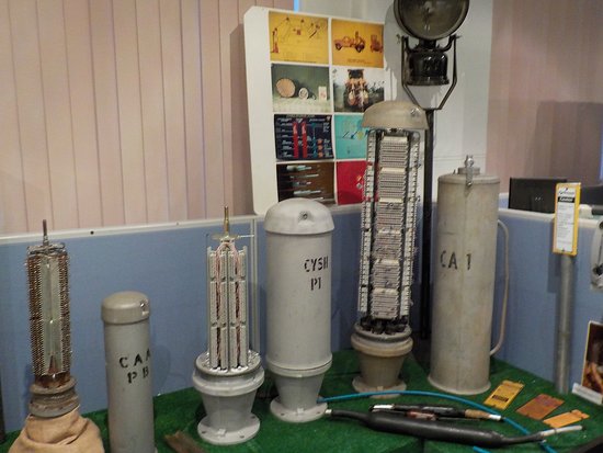
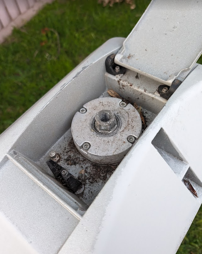
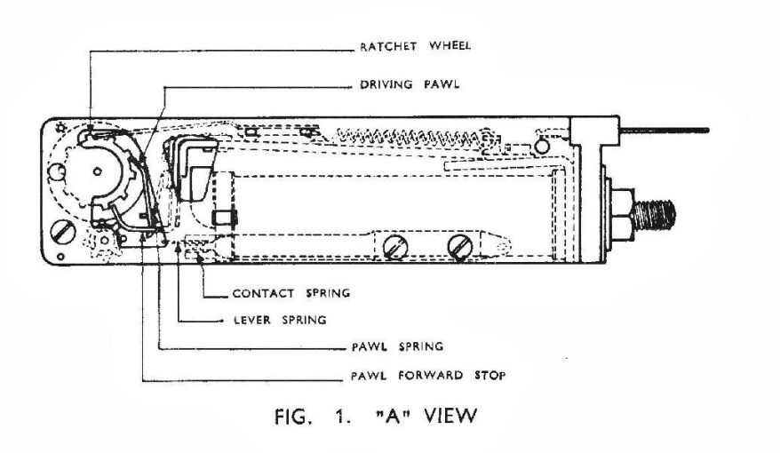
This starts with introducing the “Call Meter”, “Subscriber Meter” or “Subs Meter” for short.
Source – field, field, field and chang’s brilliantly beautiful “That Exchange Project“
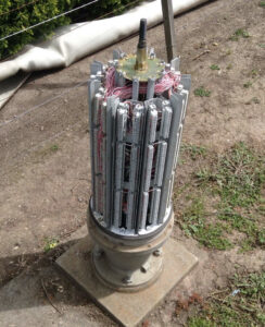
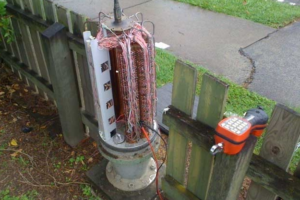
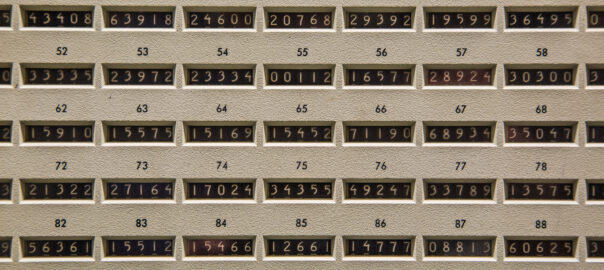
The concept is pretty simple. Each telephone service (“subscriber” in telecom parlance) provided by the local telephone exchange gets a subscriber meter or “subs meter”.
When the subscriber (customer) makes a call, and the call is answered, a reverse of polarity on the line ticks the subscriber meter over by one digit.
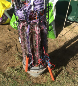
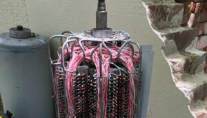
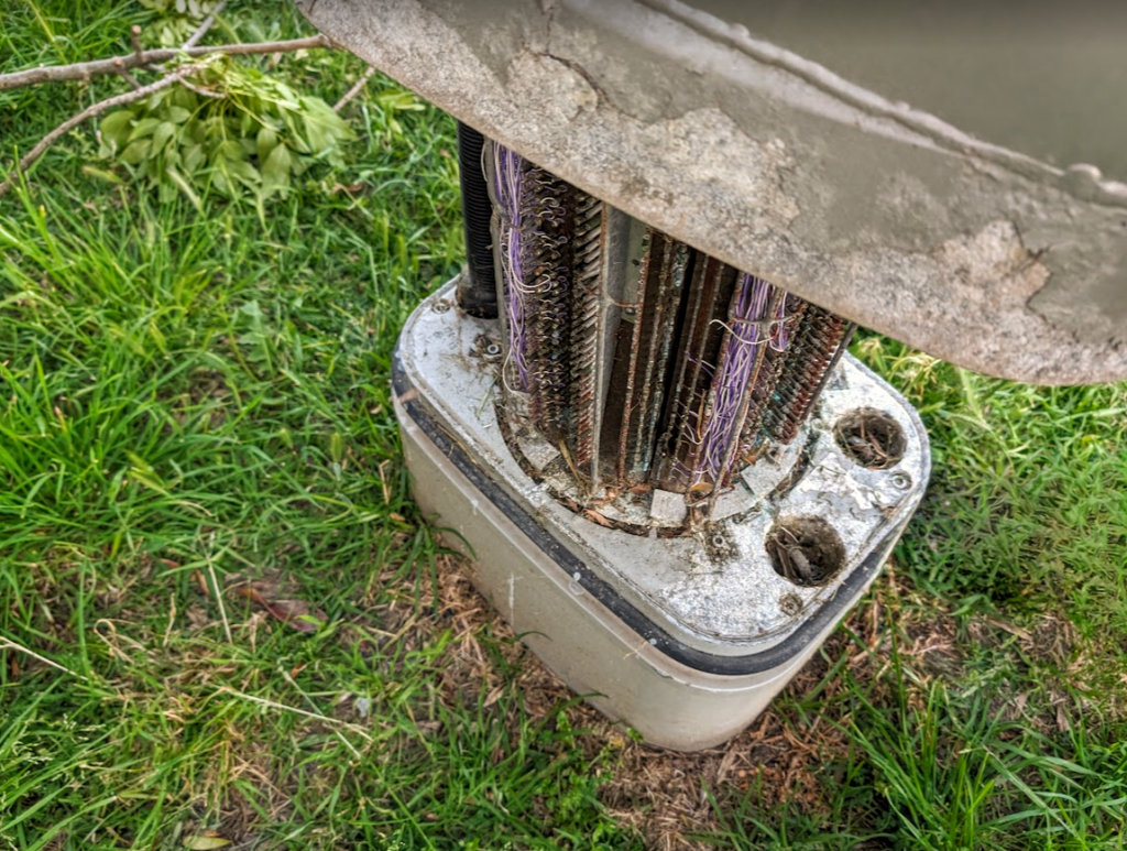
As you can imagine if you’ve got a telephone exchange that serves 10,000 customers, well you need 10,000 subscriber meters…
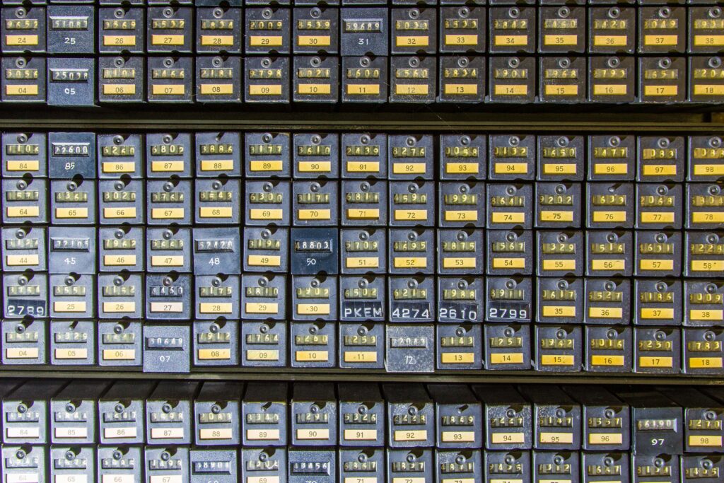
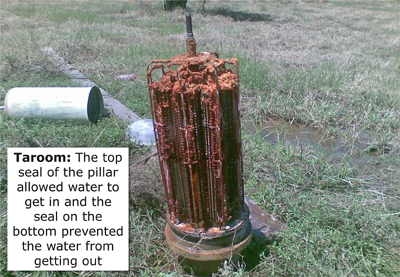
At the end of the month, someone takes a photo of all the meters on a film camera, sends it off to a billing center where they develop the photo, then calculate the difference in values from last month’s meter reading photo and this month’s meter reading photo, and bingo – there’s the number of calls the person made. You tabulate the cost on an adding machine and send off the invoice.
Today we’d just use PromQL:
delta(subscriber_meter{phone_number="123456"}[30d])
Optional Sidebar for those asking “but what about Long Distance calls where you pay per minute?” – In a world where you pay per local call, regardless of length, this works just fine, but as more complicated scenarios like long distance calling were introduced, this presented a challenge, but this could be solved by reversing the line polarity at predefined intervals, to keep ticking up the subscriber meters during the call. Exchange Clocks provided a number of pulse outputs, like 1 pulse per second, 1 pulse per minute, etc, this 1 pulse per minute signal could be hooked up to the line reversal circuit for long distance calls, to trigger the line reversal every minute. This means if a local call was $0.40 untimed, if you made long distance calls at $0.40 per minute, then you just needed the exchange to reverse the line every minute to pulse the meter. 10 increments on the meter could mean 10 x $0.40 local calls or 10 minutes of $0.40 per minute long distance.
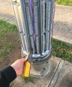
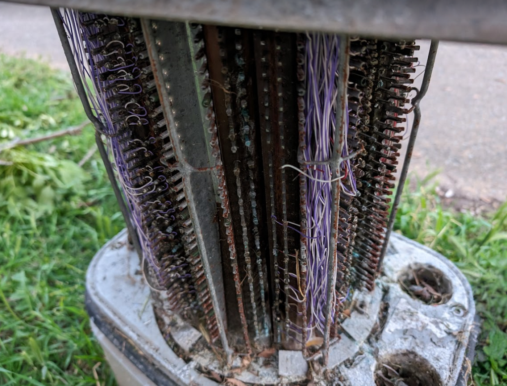
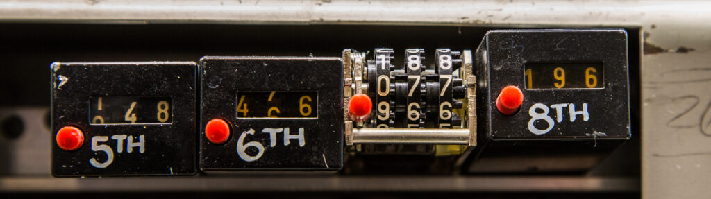
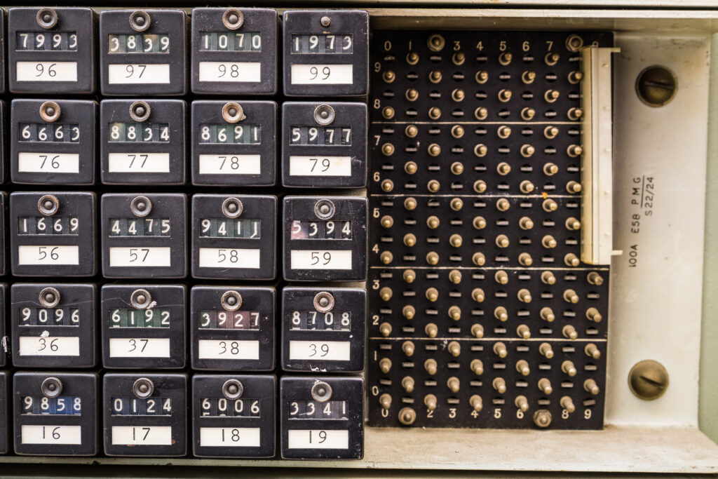
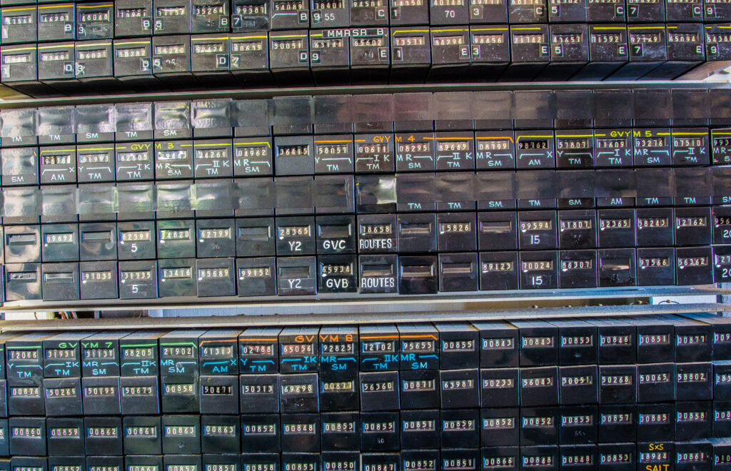
These meters were originally just for metering traffic, but engineers in the telephone network realised they could be used as generic “counters” for just about anything in the telephone network.
Let’s imagine you want to know how often a trunk line to another exchange runs out of capacity, well, you simply wire a meter to get triggered each time that condition happens, now you’ve got a counter for each time that event occurs.
Now let’s say you want to know how often you run out of final selectors, well, through another counter on it.
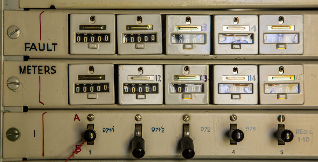
These same meters, can be wired to count fault conditions.
Source – field, field, field and chang’s brilliantly beautiful “That Exchange Project“
A pencil and a logbook is how you keep track of frequency of the event being triggered, and if you want to graph it out, graph paper, not Grafana.
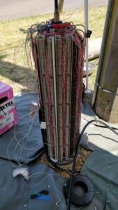
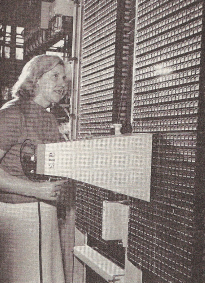
As telephone systems increased in complexity more and more meters were used to track what’s going on, up until the time that computers could start to handle that process, when “Electronic Customer Metering” came into play with the early Stored Program Control exchanges.
Source – field, field, field and chang’s brilliantly beautiful “That Exchange Project“
Observability and Metrics are so important for making software, but every time I define a “counter” in software for an event, I’m always reminded of clicking meters in an telephone exchange, knowing this is how it used to be done.