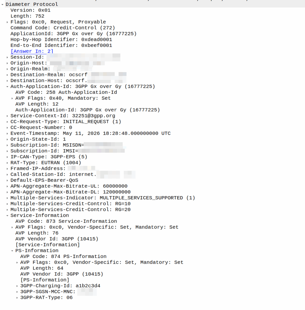
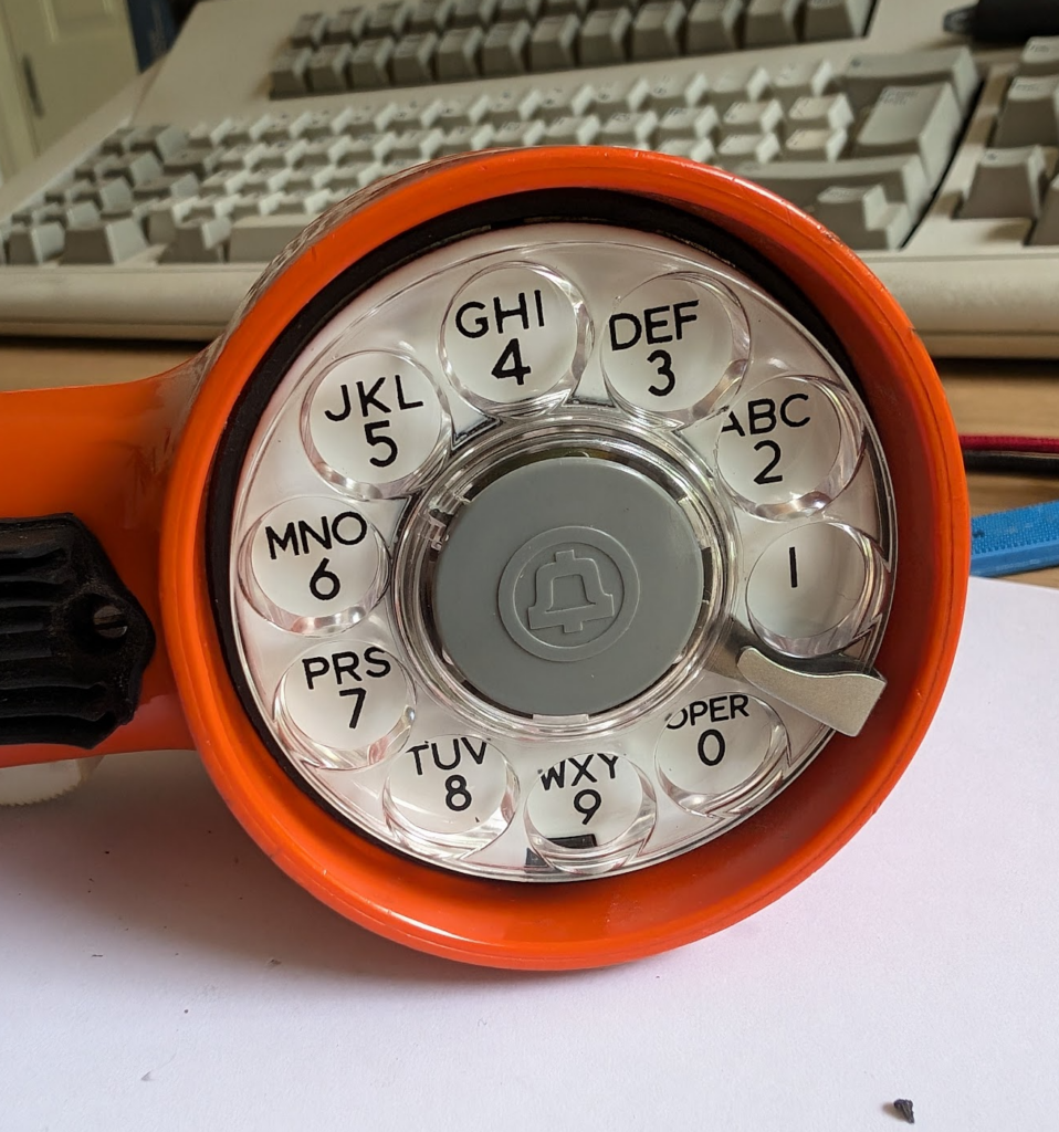
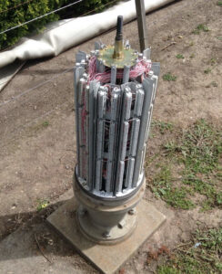
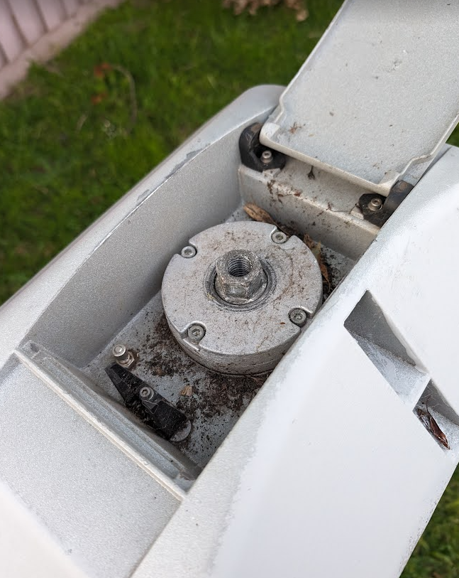
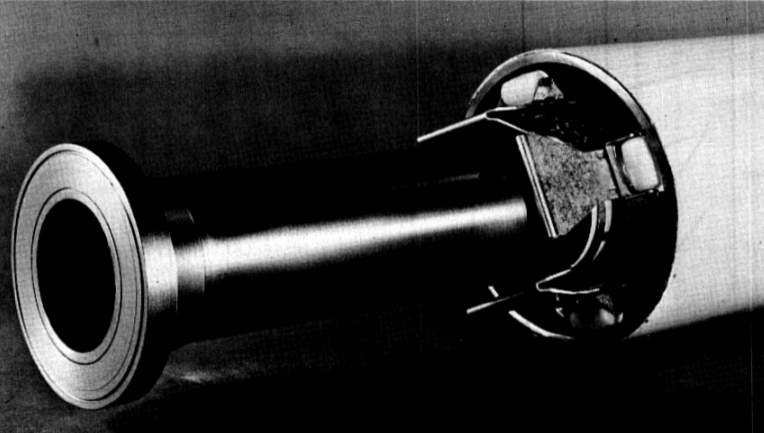
I was recently asked by a potential customer if we supported Gx over Gy.
I’d never heard of this before, so I gave my standard “If it’s in the spec we should support it, but I’ll check” answer, and got them to send me a PCAP, which I’ve got.
This is weird.
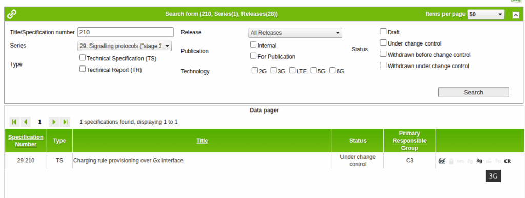
So for starers, Protocoldex has nothing for this application ID (16777225), even though it has all the LTE diameter specs.
The last version was from 2006, in 3GPP release 6, which is two years before LTE was standardized in Release 8. The word LTE does not appear in the doc or in the metadata tags.
It speaks of TPF (Traffic Plane Function) and TPF (Charging Rules Function).
LTE is “Long Term Evolution” – In later releases this draft TPF would evolve into the PGW (before the PGW-C / PGW-U divorce) and the TPF would go on to become the PCRF (and save spring break).
Reading through these early specs is like looking at Homo Eructs (get your mind out of the gutter) and knowing it evolves into Homo Sapiens.
So what does Gx over Gy do? Well, the concept is pretty straightforward, rather than needing a Sy interface between the PCRF and OCS, you can provision policy rules from the OCS, rather than on the PCRF.
So what network functions should implement this standard? Well, the P-GW specs do not reference this as something that’s included in the P-GW, nor is it in the GGSN – This was a “gooch” spec between the hypothetical standards land and real world implementations.
So will we be implementing it? Probably not. But an interesting bit of archaeology and a look through the genealogy of 3GPP.
I have run AMPS (1G) in my lab. I’ve run 2G (GSM) networks in production.
There’s a few dozen production LTE/5G networks out there I’ve put my stamp on, but…
Never, have I ever, run UMTS.
And that feels like a blind spot.
Sure, core wise 3G it reuses the 2G core (MSC / SGSN and friends). As a company, Omnitouch supports 2G, 4G & 5G networks – But we’ve never had the need to deploy 3G.
There’s a common theory that the odd-numbered “Gs” are shit. 3G/UMTS was crap, and 5G / NR standalone is kinda shit. There’s some merit to this theory.
3G/UMTS was a transitional tech, when it was worked on at the turn of the century, there was a growing recognition that this whole internet thing was going to be a big deal, but without the benefit of knowing exactly how people would use it.
In 2G, operators would configure on their networks how many “timeslots” were for voice calls and how many were for data. Imagine drawing a pie chart and rationing out this percentage for the internets, and that percentage for voice calls, and that’s pretty much how it went. The major difference (without going into the “CDMA” code thing) that 3G brought was that operators no longer had to decide the split of cat videos vs calls the network could decide the split.
Australia shut down GSM about a decade ago, and turned off UMTS close to two years ago, but many counties, including large parts of Europe, plan to operate 2G layers ’till the 2030s. While UMTS/3G survived ~20 years, GSM will be in it’s 40s at the point where it’s shut off in many countries.
As what my partner somewhat lovingly refers to as a “school holiday project” (Pointless thing I do rather than relaxing like a normal person) I set about trying to build an RNC – A “Radio Network Controller” the UMTS equivalent of a Base Station Controller in GSM, that I could connect to OmniMSC.
So I fired up the Airscale, configured an Iub link and looked at what it sent.
And the answer was a big fat nothing – the first rule of fight club is that the RNC initiates the connection.
I limped the project along to the stage where I had the cell reporting “Up” and visible, but to actually attach phones started to get into the CDMA part of allocating codes, and real life started to catch up with me.
Perhaps someday I’ll continue the work, but the sad truth is there’s almost no scenarios today where you wouldn’t be better to deploy LTE and a GSM layer if you need to support legacy devices – the smallest UMTS carrier is 5Mhz, and while you can’t do 1:1 frequency reuse in GSM, you’ve got 20x unique GSM TRXes in that same 5Mhz you can use.
So for now, I’m giving up, knowing slightly more about RNC architecture, but still having never done a UMTS attach.
Over a decade ago, Dan McKinley published a blog post titled “Choose Boring Technology” which advocates that software developers and engineers design systems using “boring” technology.
One of the most worthwhile exercises I recommend here is to consider how you would solve your immediate problem without adding anything new. First, posing this question should detect the situation where the “problem” is that someone really wants to use the technology. If that is the case, you should immediately abort.
In the long time since he wrote that post, I feel like a lot of the tech industry has matured in it’s approach and learned these lessons – We’re not jumping onto the bleeding edge new-fangled tools as much, and instead developers and engineers are sticking towards tried and tested design patterns in order to achieve the business goals.
No Hayden, this doesn’t mean I’ll write PHP.
But it feels like in telecom at least, leadership teams have not learned this lesson.
Every telco conference I go to I hear about “telco to tech co transformation” in presentations from telecom CTOs on the verge of retirement, and it’s bullshit.
We are a boring tool – Telecom is the boring technology.
Boring it may be, but customers have only shown a demand for connectivity from telecom operators.
End customers aren’t showing demand for TV content from their operators (sports rights anyone?), bundled services, AI something, metaverse, connected cars, crypto, 5G slicing, containers, edge, robotic surgery or whatever else is being shilled as the next best thing for telecom operators.
The idea of diversifying into other revenue streams fails to ask the question of why telcos would be better suited to deliver value in those markets than literally every other organization on the planet. In the majority of cases, there’s no strong case to be made for telcos to take the lead here. Telecom projects generally have a much higher failure rate than that of most other sectors in tech, so why would telcos be best suited to these new industries?
Customers have consistently shown demand for fast, reliable, affordable access to connectivity, and only that. That’s what customers want from us as an industry – We should have a laser like focus on delivering that, better and better year on year, and not chasing distractions.
As an example, go to Google Maps reviews, or Down Detector and find the feedback from customers of any given telco. While telcos crow about NPS the lived experience of customers – justified or not, is often pretty piss poor.
Chasing becoming a tech-co distracts from the core business for a network operator, of, well, operating the network.
Any talk of “business transformation” and shifting to becoming a tech-co just distracts from that mission.
We’re largely utilities and we’re not sexy, but that’s okay.
We all know Bell Labs, Australia’s Telecom labs and others produced some amazing technology inventions and were at the forefront of tech in their day – Shockley, Shannon, etc. But that was finished by the 1970s, and required a state monopoly and with an R&D budget that rivaled that of many small countries. That monopoly is gone, and that money is gone. We can’t compete on broad tech innovation.
But consistently, since the telephone was first introduced in the 1800s, communications has been what customers want.
What we do isn’t shiny, but it is critical, and there’s still plenty of room for improvement in our space, to do things better. I hope we as an industry focus on just doing what we do now but better, and embrace being a boring technology.
Turns out it was great training for a career in telecom; I learned basic rigging, working at heights, electrical work, patching rats nests of cables and the shared camaraderie that comes from having stayed up all night working on something no one would ever notice, unless you hadn’t done it.
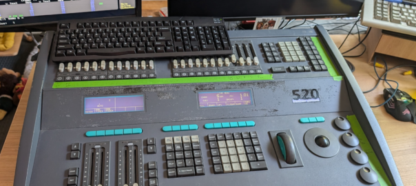
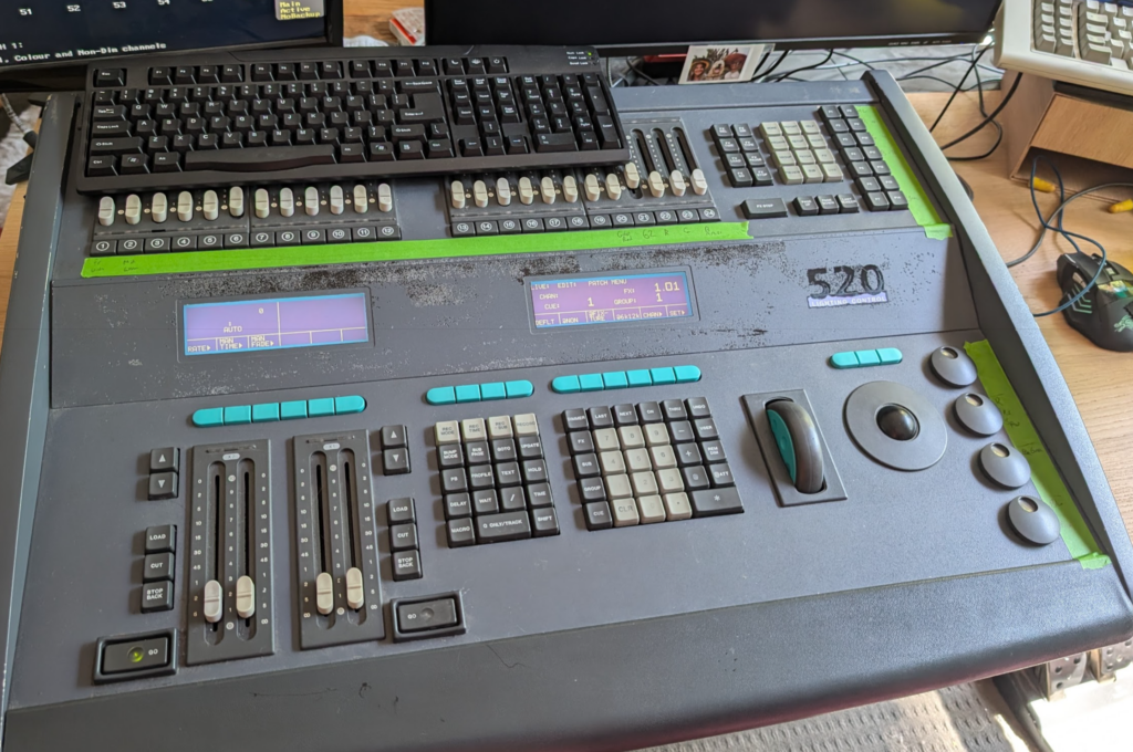
At the time the Strand 520i lighting console was the coolest thing ever, it had support for 4 DMX universes (2048 channels – Who could ever need more than that!?) and cost more than a new car.
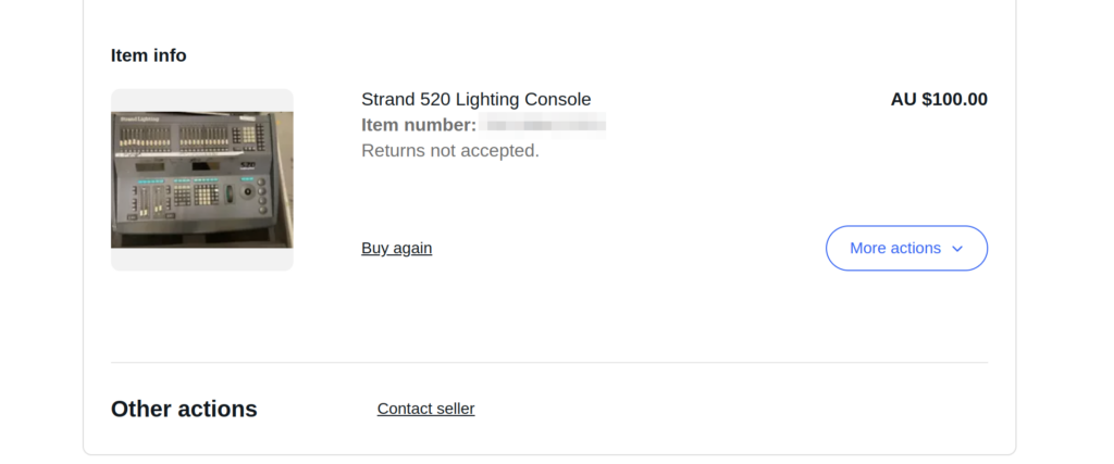
One late Friday night browsing online I found one for sale by a University in the state I live in, for $100 or best offer. You better believe I smashed the buy now button so hard my mouse almost broke. I was going to own my very own Strand 520.
I spent the weekend reading through the old manuals, remembering how to use all the features, then dragged my partner for the road trip the following Monday morning to pick it up and bring it home.
But before I could do anything fun I had to find a PS/2 keyboard and a VGA screen, which took me a few more days (a visit to the tip was the easiest way to get a hold of them).
Then I needed something to receive DMX – I found everything now uses ArtNet (DMX over IP) and there’s visualisers for simulating an arena / stage lighting setup, but all take ArtNet now, so I ordered a DMX to ArtNet converter.
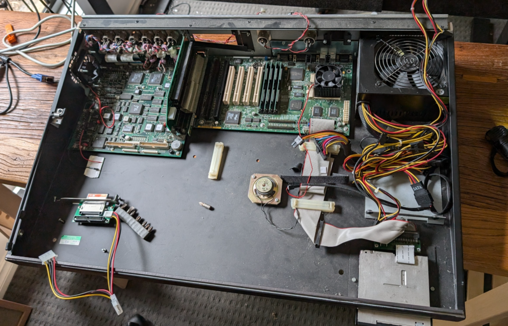
Inside the unit is pretty much a standard PC (An “OG” Pentium in the Strand 520) with an ISA card for all the lighting control stuff.
The clicking hard drive managed to boot, but I didn’t think it’d last long, having been made more than 25 years prior. So I created a disk image and copied the file system onto a CF card using a CF to IDE adapter. This trick meant it booted faster than ever before.
Clicky HDD before it became a CF
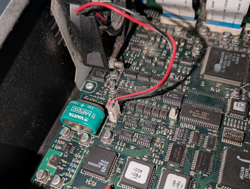
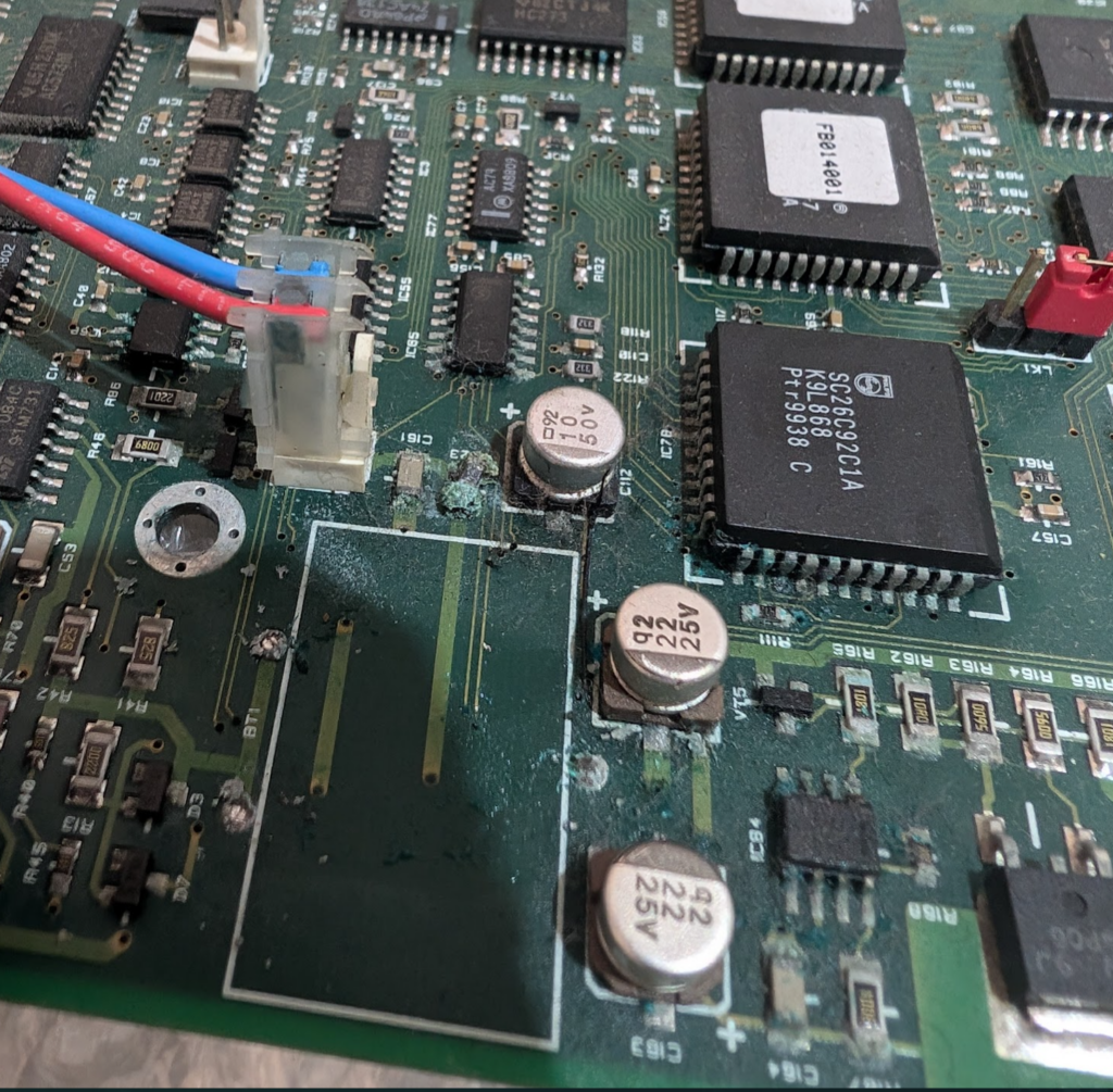
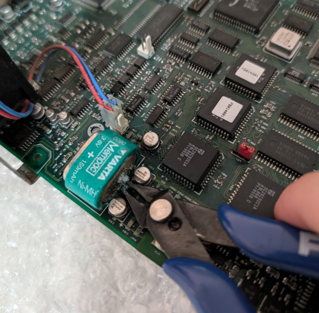
One thing I’d read about online was the VARTA battery had a tendency to leak battery acid all over the PCB. This one had yet to fully spill its guts, but was looking a bit bulgey and had started to leak a little already.
The battery (I’d read) was only for storing info in a power loss scenario, and if the battery isn’t present it just slows the boot time as everything has to be read from disk, so I took the leap of faith and cut the battery out, and lo, it still all boots.
Slightly furry VARTA battery
So now I was OK to get the desk online properly, but was getting semi-regular lock ups where DMX would stop outputting and inputs on the console were not read, but the underlying PC was still working.
I spent a lot time debugging this. BIOS settings, interrupts, I dived into how ISA works, replaced the battery I removed with a brand new one, and at one point I broke out the oscilloscope, but nothing worked.
Around the same time I noticed the Ethernet port (BNC!) would work if I just ran plain DOS (could ping from DOS but when the application started the NIC would go dead), which made me think I may be facing a hardware fault with the “CS” – the show processor for the console which is what the motherboard connects to via ISA.
The desk itself with the face off, and the CF adapter being mounted
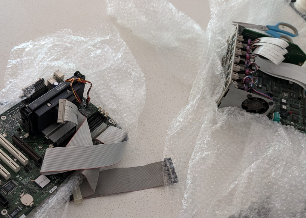
Alas being almost 30 years old (this unit was made in 1996) there aren’t a great number of them around to test with, so I could try swapping out the “CS” board. What I did find was another complete console on eBay for $50 but it was in the UK, and they weigh a lot. Shipping this thing was not an option.
But for a bit of of extra cash the seller was willing to crack the case open and strip out the two main boards and post me just those. This had added bonus that the motherboard and CPU of the board sent from the UK was a 520i meaning it has the Pentium II processor – This Strand 520 was now going to be a Strand 520i.
A month later a box appeared at my door containing the boards, but the battery on the CS board from the UK had well and truly spilled its guts, leaving some toxic sludge around all the components nearby. A can of PCB cleaner and a toothbrush (which I will not be using to brush teeth with anymore) and I’d cleaned it up as best I could, but the fan output from the board was well and truly dead, with some of the SMD components just eaten by the acid.
So I put everything back into the case and wired it up. The mounts for the Motherboard were slightly different, and the software that is used for the 520i is different from the 520 (without the i).
The HDD from the UK was unable to boot, but I was able to get it to spin up enough to copy off the ~5Mb of files I needed, then I did a fresh install of MS DOS and copied the installer for the StrandOS.
Finally fully functional
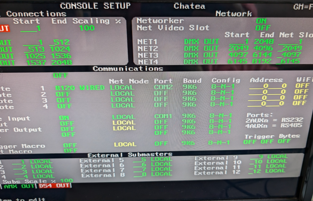
Finally I had a stable working console. Not just that but the Strand Networker application was now available to me. So I plugged into the 10Mbps connection and set the console to output to Network as well as DMX.
Enabling the “networker” for network DMX transmission
I cranked open Wireshark and there was a mystery signal sent to the broadcast address on UDP…
I patched a single DMX channel and changed the value and when I viewed the data in Wireshark I could see a hex representation of the DMX 0-255 value.
Easy I thought to myself, it’ll just be a grid of channels, each with their value as hex. Ha! I was wrong.
Turns out Strand Shownet used a conditional form of “Run Length Encoding” compression, where if you’ve got channels 1 through 5 at 50% rather than encoding this is 5 bytes each showing 0x80, it uses 2 bytes, to indicate 5 sequential channels (run length) and then the value (0x80). Then there’s another bit to denote how many forward places to move and if the next channel is using RLE or not.
The code got messy; it’s not the best thing I’ve ever written but it works for 2 full universes of DMX (I need to spend more time to understand where the channel encoding overflow happens as I end up a few channels ahead of where I should be on universe 3 and above).
The code is available on Github and I’d love to know if anyone’s using it with these old dinosaurs!
I love Grafana. I love metrics and observability. Nothing is more powerful than being able to see what’s going on inside your network/application/solar setup/weather station – you name it.
It’s never been easier to see what’s going on.
If I wanted to monitor my web app as I onboard more customers, Grafana is the go-to tool, but how was it done before the computer age? Let’s go back to the 1940s and look at how the telephone network handled observability and metrics…
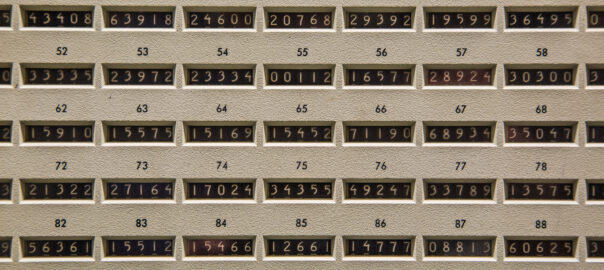
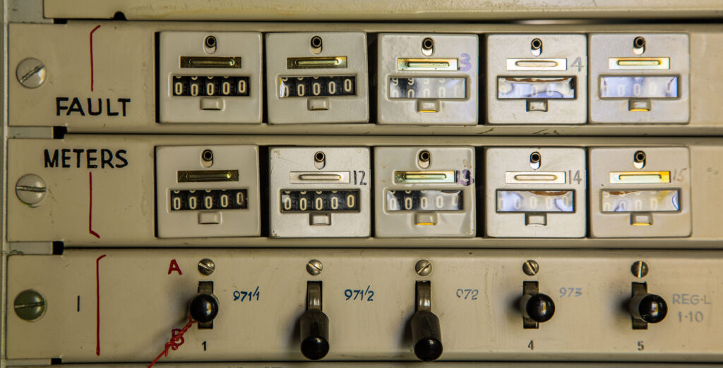
This starts with introducing the “Call Meter”, “Subscriber Meter” or “Subs Meter” for short.
Detail of mechanical call meter Strathfield South Exchange Source – field, field, field and chang’s brilliantly beautiful “That Exchange Project“
The concept is pretty simple. Each telephone service (“subscriber” in telecom parlance) provided by the local telephone exchange gets a subscriber meter or “subs meter”.
When the subscriber (customer) makes a call, and the call is answered, a reverse of polarity on the line ticks the subscriber meter over by one digit.
Each of the meters on the left is a single telephone subscriber, each time they make a call, the meter ticks up by one position. Source – field, field, field and chang’s brilliantly beautiful “That Exchange Project“
As you can imagine if you’ve got a telephone exchange that serves 10,000 customers, well you need 10,000 subscriber meters…
You need a lot of meters… Source – field, field, field and chang’s brilliantly beautiful “That Exchange Project“
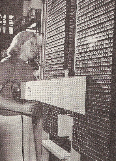
At the end of the month, someone takes a photo of all the meters on a film camera, sends it off to a billing center where they develop the photo, then calculate the difference in values from last month’s meter reading photo and this month’s meter reading photo, and bingo – there’s the number of calls the person made. You tabulate the cost on an adding machine and send off the invoice.
Each of the little blocks is a single subscriber to meter and the weird cone thing held is a hood for the camera to photograph the values – Source The Communications Museum Trust
Optional Sidebar for those asking “but what about Long Distance calls where you pay per minute?” – In a world where you pay per local call, regardless of length, this works just fine, but as more complicated scenarios like long distance calling were introduced, this presented a challenge, but this could be solved by reversing the line polarity at predefined intervals, to keep ticking up the subscriber meters during the call. Exchange Clocks provided a number of pulse outputs, like 1 pulse per second, 1 pulse per minute, etc, this 1 pulse per minute signal could be hooked up to the line reversal circuit for long distance calls, to trigger the line reversal every minute. This means if a local call was $0.40 untimed, if you made long distance calls at $0.40 per minute, then you just needed the exchange to reverse the line every minute to pulse the meter. 10 increments on the meter could mean 10 x $0.40 local calls or 10 minutes of $0.40 per minute long distance.
These meters were originally just for metering traffic, but engineers in the telephone network realised they could be used as generic “counters” for just about anything in the telephone network.
Let’s imagine you want to know how often a trunk line to another exchange runs out of capacity, well, you simply wire a meter to get triggered each time that condition happens, now you’ve got a counter for each time that event occurs.
Now let’s say you want to know how often you run out of final selectors, well, through another counter on it.
These same meters, can be wired to count fault conditions.
Mechanical fault meters on old step-by-step test desk, Queanbeyan Exchange Source – field, field, field and chang’s brilliantly beautiful “That Exchange Project“
A pencil and a logbook is how you keep track of frequency of the event being triggered, and if you want to graph it out, graph paper, not Grafana.
As telephone systems increased in complexity more and more meters were used to track what’s going on, up until the time that computers could start to handle that process, when “Electronic Customer Metering” came into play with the early Stored Program Control exchanges.
Metering and charging equipment in Blakehurst Exchange Source – field, field, field and chang’s brilliantly beautiful “That Exchange Project“
Observability and Metrics are so important for making software, but every time I define a “counter” in software for an event, I’m always reminded of clicking meters in an telephone exchange, knowing this is how it used to be done.
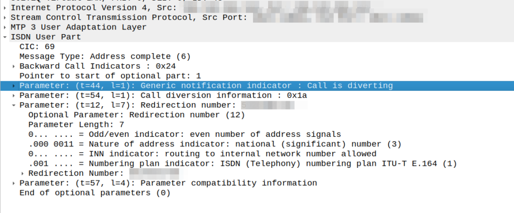
Had an interesting fault come across my desk the other day; calls were failing when the called party (an SSP we talk to via SS7/ISUP) had an exchange based call forward in place.
We’re a SIP based network, but we do talk some SS7/ISUP on the edges, and it was important that we handled this correctly.
I could see in the Address Complete Message (ACM) sent back to our network that there was redirection information here:
We would see the B party SSP release the call as soon as it sent this.
This made me wonder if we, as the originating network, were supposed to redirect to the new B party and send a new Initial Address Message?
After a lot of digging in the ITU Q.7xx docs (I’m not where near as fast at finding information in specs written prior to my birth, than I am with the 3GPP specs) I found my answer – These headers are informational only, the B party SSP is meant to re-target the message, and send us an Alerting or Answer message when it’s done so.
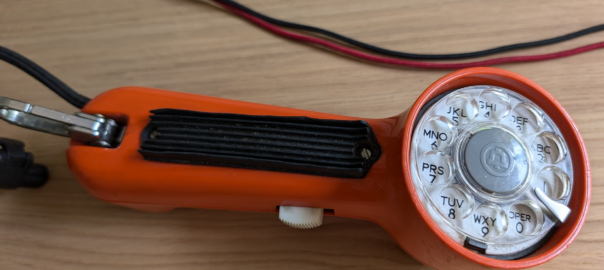
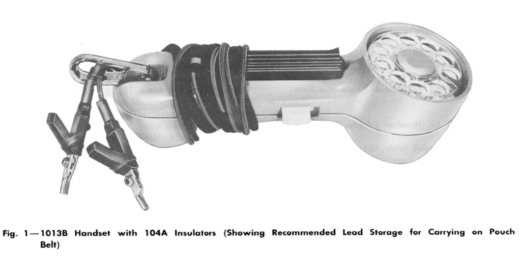
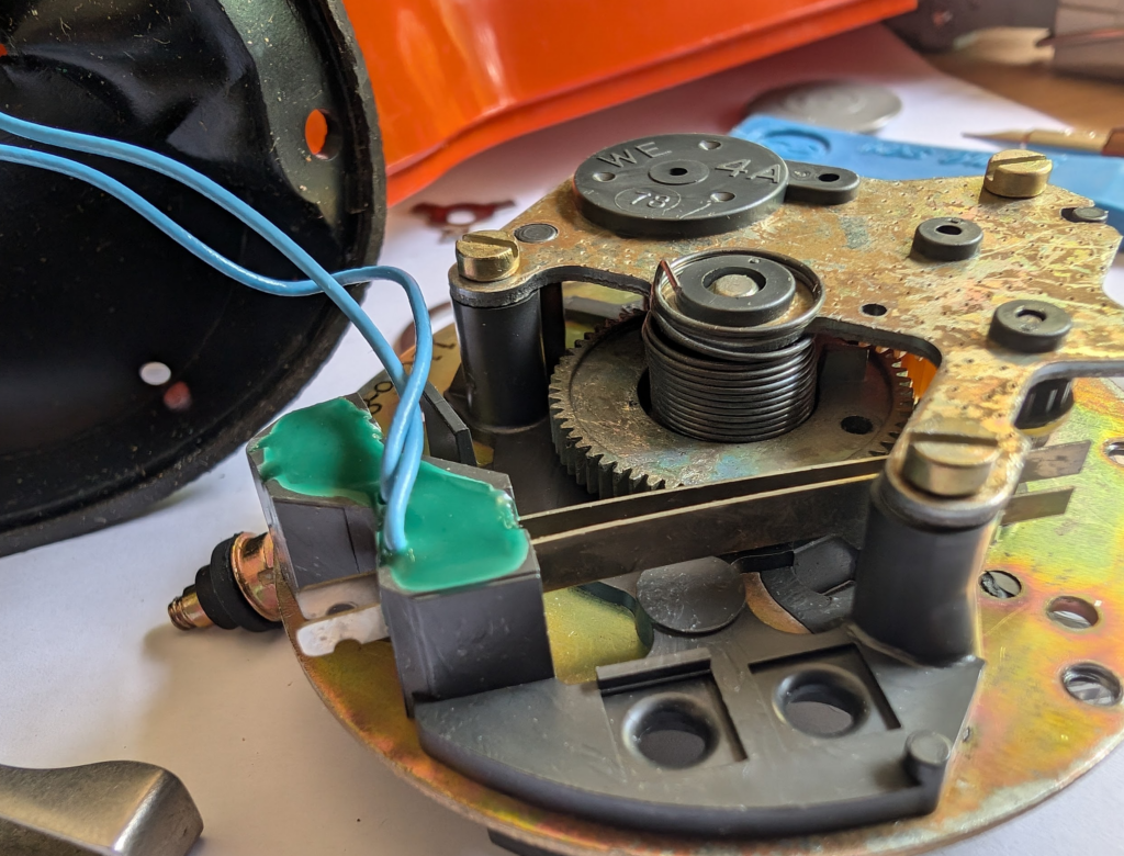
I recently picked up a Western Electric 1013 Test set (Aka Buttinski) rotary test phone.
These are about $10 a piece on eBay in the US, and when having a pile of other stuff sent over (*cough* Nortel Millennium *cough*) I figured I’d add one of these.
I imagine these were produced in massive numbers, they’re electrically very simple, hardened and feature a rubber strip for a “more secure hands-free operation” – Luxury.
Electrically these are very simple, and it’s 3 screws to open the whole unit up, and the top and bottom half separate with spring loaded contacts for the dial so you don’t need to unplug anything (I imagine because they had a habit of getting broken dials when being smashed around).
Oddly there is no ringer circuit, bell or lamp, so although you could answer an incoming call with one of these, there’s no way you’d know it was ringing, which reminded me of this sketch from “Not the Nine O’Clock News”.
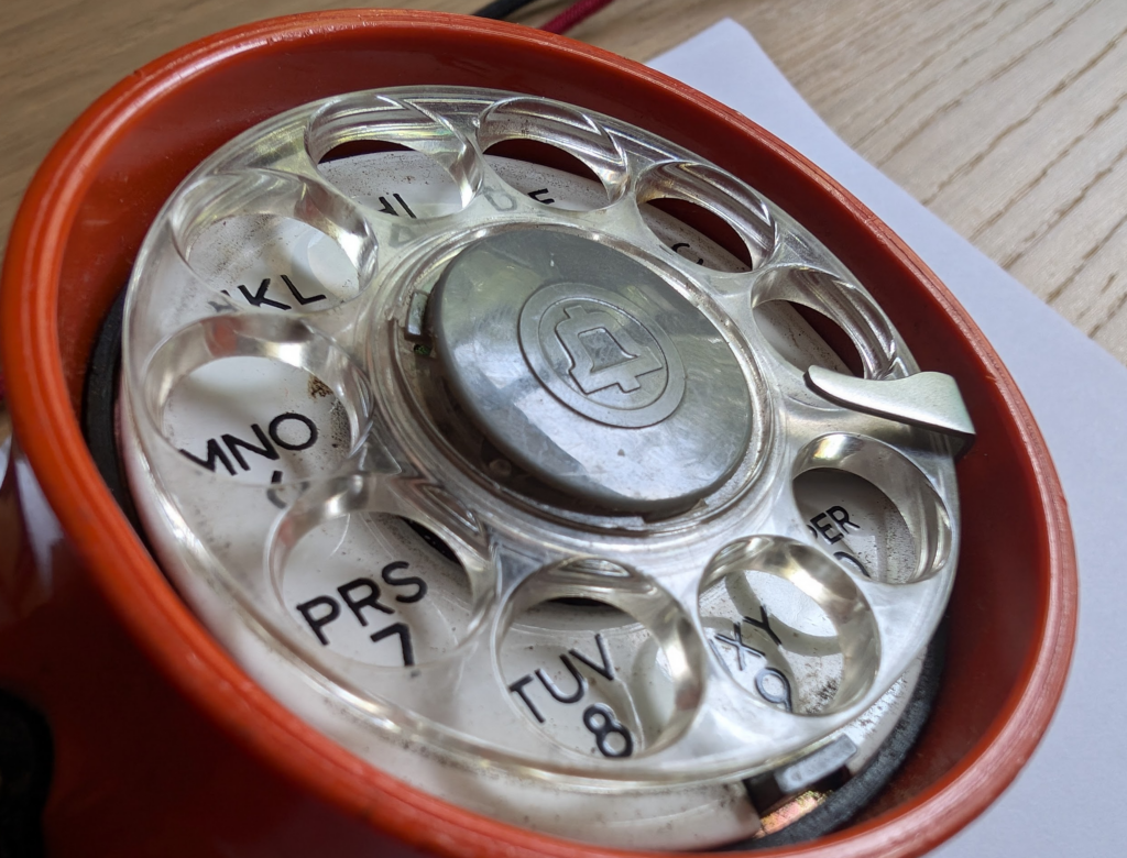
According to the datasheet these phones feature an “type 11C dial”.
TCI library also has the docs for the Type 10 and Type 11 dial, which, according to Ma Bell, is not field serviceable, and should be swapped out rather than attempting a repair.
Rotary dial in action
Alas the rotary dial on mine was running slightly slow, I’ve a feeling Western Electric doesn’t manufacture these any more, so I decided I’d have to fix it myself.
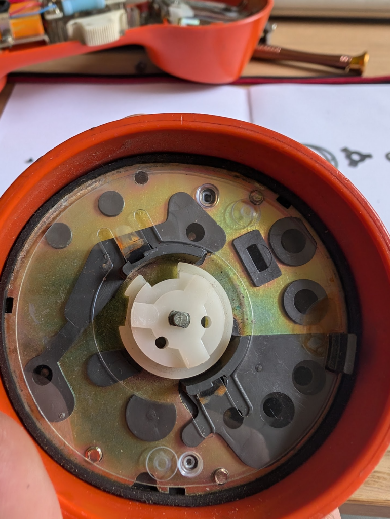
So I stripped down the dial and gave it a good clean.
The dial has a neat little rubber boot on the inside to protect it from gunk, and came apart and went back together easily enough, even if I did inadvertently let out all the spring tension and have to wind it back in, and put the dial on offset by 90 degrees.
Oddly the finger stop moves when you dial – I thought this was an issue with a loose part, but it’s by design, to allow the dial to be more compact, which makes total sense as if I had stopped it from moving I wouldn’t be able to dial higher numbers – Glad I worked that one out eventually.
With the dial cleaned up and adjusted, she’s dialing within spec.
After cleaning and reassemblyBeforePROPERTY OFDial when cleanedReassemblyInterrupter on rotary dialRemoving the Bell logo from the fingerplateDial removed
When Dickens wrote of Doctor Manette in the 1859, I doubt his intention was to write about the repeating history of RAN fronthaul standards – but I can’t really say for sure.
Setting the Scene
Our story starts with introducing CPRI (Common Public Radio Interface) interface, having been imprisoned in the Bastille of vendor lock in for the better part of twenty years.
Think of CPRI is less of a hard interoperable standard and more like how the Italian and French languages are both derived from Latin; it doesn’t mean that the two languages are the same, but they’ve got the same root and may share some common words and structures.
In practice this means that taking an Ericsson Radio and plugging it into a Huawei Baseband simply won’t work – With CPRI you must use the same vendor for the Baseband and the Radios.
“Nuts to this” the industry said after being stuck locked between the same radios and baseband for years; we should create a standard so we can mix and match between radio vendors, and even standardize some other stuff that’s been bothering us, so we’ll have a happy world of interoperability.
A world with interoperable fronthaul
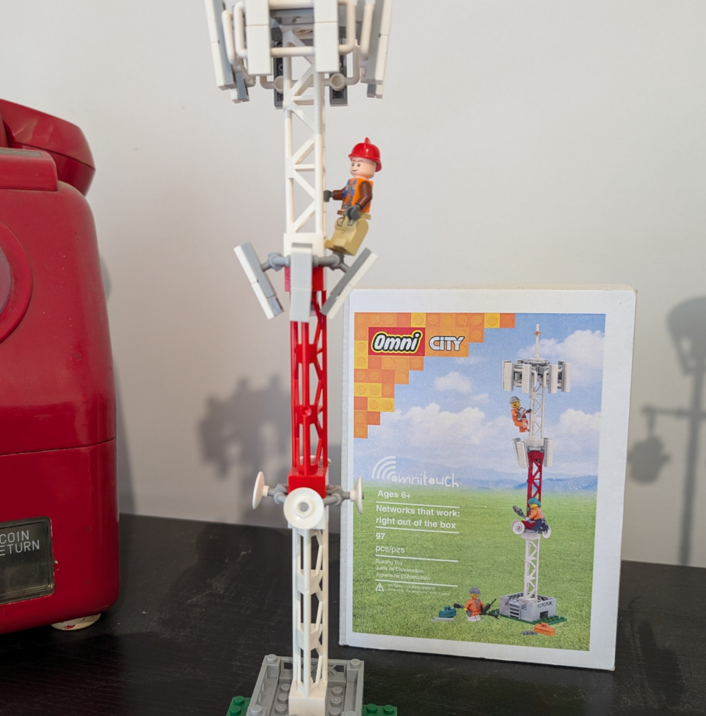
With kit created that followed this standard, we’d be able to take components from vendor A, B & C, and fit them together like Lego, saving you some money along the way and giving you’ve got a working solution made of “best of breed” components, where everything is interoperable.
Omnitouch Lego base stations, which also fit together like Lego – Part of the Omnitouch Network Services “swag” from 2024
So the industry created a group to chart a path for a better tomorrow by standardizing these interfaces.
The group had many industry heavyweights like Nokia, NEC, LG, ZTE and Samsung joining.
The key benefits espoused on their website:
An open market will substantially reduce the development effort and costs that have been traditionally associated with creating new base station product ranges. The availability of off-the-shelf base station modules will enable manufacturers to focus their development efforts on creating further added value within the base station, encouraging greater innovation and more cost-effective products. Furthermore, as product development cycles will be reduced, new base station functions will become available on the market more quickly.
Mission statement of the group
In addition to being able to mix and match radios and basebands from different vendors, the group defined standards for centralized baseband, and interoperable standards, to allow a multi-vendor ecosystem to flourish.
And here’s the plot twist – The text above, was not written about OpenRAN, and it was not written about the benefits of eCPRI.
It was written about Open Base Station Architecture Initiative (OBSAI) and it was written 22 years ago.
*record screech sound*
Standards War you’ve never heard of: OBSAI vs CPRI
When OBSAI was defined it was not without competition; there was another competing fronthaul standard; that’s right, the mustache twirling lowlife from earlier in the story – CPRI.
Supported by Huawei, Nortel, NEC & Ericsson (among others), CPRI took a “gentle parenting” approach to the standards world, in contrast to OBSAI. Instead of telling all the vendors to agree on an interoperable front haul standard, CPRI just encouraged everyone to implement what their heart told them and what felt right to them.
As it happened, the industry favored the CPRI approach.
If a vendor wanted to add a new “word” in their CPRI “language” to add a new feature, they just went ahead and added it – It didn’t require anyone else to agree with them or changes to a common standard used by the industry, vendors could talk to the kit they made how they wanted.
CPRI has been the defacto non-standard used by all the big kit vendors for the past ~10 years.
The Death of OBSAI & the Birth of OpenRAN’s eCPRI
Why haven’t you heard of OBSAI? Why didn’t the OBSAI standard just serve as the basis for eCPRI – After all the last OBSAI release was less than 5 years before TIP started working on eCPRI publicly.
Is no more. It has ceased to be.
Did a schism over “uplink performance improvement” options lead to “irreconcilable differences” between parties leading to the breakup of the OBSAI group?
Nope.
Customers (MNOs) didn’t buy OBSAI based equipment in measurably larger quantities than CPRI kit. That’s it.
This meant the vendors invested less in paying teams to further develop the standards, the OBSAI group met less frequently, and in the end, member vendors didn’t bother adding support for OBSAI to new equipment and just used the easier and more flexible CPRI option instead.
At some point someone just stopped paying for the domain renewal and that was it, OBSAI was no more.
This is how the standards body ends, not with a bang, but with a whimper.
T.S. Elliot’s writings on the death of obsai
Those who do not learn from history…
The goals of the OBSAI Group and OpenRAN working groups are almost identical, so what lessons did Marconi, Motorola and Alcatel learn as members of OBSAI that other vendors could learn about OpenRAN strategy?
There are no mentions of OBSAI in any of the information published by OpenRAN advocates, and I’m wondering if folks aren’t aware that history tends to repeat and are ignorant to what came before it, or they’re just not learning lessons from the past?
So what can the OpenRAN industry learn from OBSAI?
Being a nerd, I started detailing the technical challenges, but that’s all window dressing; The biggest hurdle facing CPRI vs eCPRI are the same challenges OBSAI vs CPRI faced a decade prior:
To be relevant, OpenRAN kit has to be demonstrably better than what we have today AND provide a tangible cost saving.
OBSAI failed at achieving this, and so failed to meet it’s other more noble goals.
[At the time of writing this at least] I’d contend that neither of those two criteria have been met by OpenRAN.
What does the future hold for OpenRAN?
Looking into the crystal ball, will OpenRAN and eCPRI go the way of OBSAI, or will someone keep the OpenRAN dream alive?
Today, we’re still seeing the MNOs continue to provide tokenistic investment in OpenRAN. But being a cynic, I’d say the MNOs are feigning interest in OpenRAN products because it’s advantageous for them to do so.
The threat of OpenRAN has proven to be a great stick to beat the traditional vendors with to force them to lower their prices.
Think about the $14 billion USD Ericsson deal with AT&T, if chucking a few million at OpenRAN pilots / trials lead to AT&T getting even a 0.1% reduction in what they’re paying Ericsson, then the numbers would have worked out well in AT&Ts favor.
From the MNOs perspective, the cost to throw the odd pilot or trial to a hungry OpenRAN vendor to keep them on the hook is negligible, but the threat of OpenRAN provides leverage and bargaining power every time it’s contract renewal time with the big RAN vendors.
Already we’ve seen all the traditional RAN vendors move to neutralize this threat by introducing “OpenRAN compatible” equipment and talking up their commitment to openness.
This move by the RAN vendors takes this sting out of the OpenRAN threat, and means MNOs won’t have much reason to continue supporting OpenRAN.
This leaves the remaining OpenRAN vendors like Miss Havisham, forever waiting in their proverbial wedding dresses, having being left at the altar.
Okay, I’m mixing my Dickens’ references here, but it was too good not to.
Appendix
I’ve been enjoying writing more analysis than just technical content, let me know if this is something you’re interested in seeing more of.
I’ve been involved in two big OpenRAN integration projects, both of which went poorly and probably tainted my perspective. Enough time has passed to probably write up how it all went with the vendor names removed, but that’s a post for another time!
This is the next post in my series on SS7, and today we’re taking a look at SCCP the Signalling Connection Control Part (SCCP).
High Level
Global Title uses the routing features from SCCP, which is another layer on top of MTP3.
SCCP allows us to route on more than just point code, instead we can route based on two new fields, Subsystem Number and Global Title.
Subsystem Number is the type of system we are looking to reach, ie an HLR, MSC, CAMEL Gateway, etc.
The Global Title generally looks like an E.164 formatted phone number, and often it is just that.
Somewhere along the chain (typically at the end of it) an STP somewhere needs to perform Global Title Translation to analyse the SCCP header (Subsystem Number, Point Code & Global Title) and finally turn that into a single point code to route the MTP3 message to.
The advantage of this is we are no longer just limited to routing messages based on Point Code.
This is how the international SS7 Network used for roaming is structured and addressed – All using Global Title rather than Point Codes.
The need for SCCP
For starters, after all this talk of MTP3 and Point Codes, why the need to add SCCP?
Let’s go back in time and look at the motivators…
1. Address space is finite
Point codes are great, and when we’ve spoken about them before, I’ve compared them to IPv4 address, but rather than ranging from 0.0.0.0 to 255.255.255.255 (32 bits on IPv4) international signaling point codes range from 0.0.0 to 7.255.7 (14 bits).
The problem with IPv4’s 32 bit addresses is they run out. The problem with the ITU International Signaling Point Codes is that they too, are a limited resource with only 16,383 possible ISPCs.
~700 operators worldwide each with ~100 network elements would be 70k point codes to address them all – That’s not going to fit into our 16k possible Point Codes.
Global Title fixes this, because we’re able to use E.164 phone number ranges (which are plentiful) for addressing, we’re still not at IPv6 levels of address space, but pretty hefty.
2. Service Discovery by Subsystem
Now imagine you’re a VLR looking to find an HLR. The VLR and the HLR are both connected to an STP, but how does the VLR know where to reach the HLR?
One option would be to statically set every route for the Point Code of every HLR into every possible VLR and visa-versa, but that gets messy fast.
What if the VLR could just send a request to the STP and indicate that the request needs to be routed to any HLR, and the STP takes care of finding a SS7 node capable of handling the request, much a Diameter Routing Agent routes based on Application ID.
SCCP’s “Subsystem Number” routing can handle this as we can route based on SSN.
3. Service Discovery by MSISDN
Having an SMS destined to a given MSISDN requires the SMSc to know where to route it.
Likewise an MSC wanting to call a given number.
There’s a lot of MSISDN ranges. Like a lot. Like every phone mobile number.
Having every a table on every SSP/SCP in the network know where every MSISDN range is in the world and what point code to go through to reach it is not practical.
Instead, being able to have the SCP/SSPs (like our MSC or SMSc) send all off-net traffic to an STP frees us the individual SCP/SSPs from this role; they just forward it to their connected STP.
Our STP can analyse the destination MSISDN and make these routing decisions for us, using Global Title Translation based on rules in the Global Title Table on the STP.
For example by adding each of the domestic / national MSISDN ranges/prefixes into the Global Title Table on the STP (along with the corresponding point code to route each one to), the STP can look at the destination MSISDN in the message and forward to the STP for the correct operator.
Likewise a route can match anything where the Global Title address is outside of the local country and send it to an international signaling provider.
Global title takes care of this as we can route based on a phone number.
4. Tokenistic Security
By “Hiding” network elements behind Global Titles, you don’t expose as much information about your internal network, and the only way people can “find” your network elements would be scanning through all the possible addresses in your (publicly advertised) Global Title range (wardialing is back baby!).
But the phrases “Security” and “SS7” don’t really belong together…
The SCCP Header
The SCCP header has a Called Party and a Calling Party, and this is where the magic happens.
These can be made up for any number of 3 parts:
Global Title Address
Subsystem Number
Point Code
We can route on any combination of these.
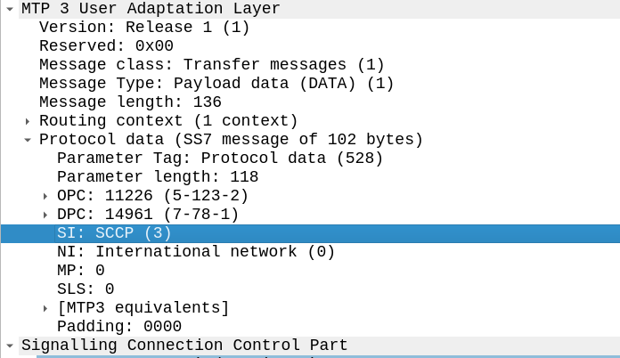
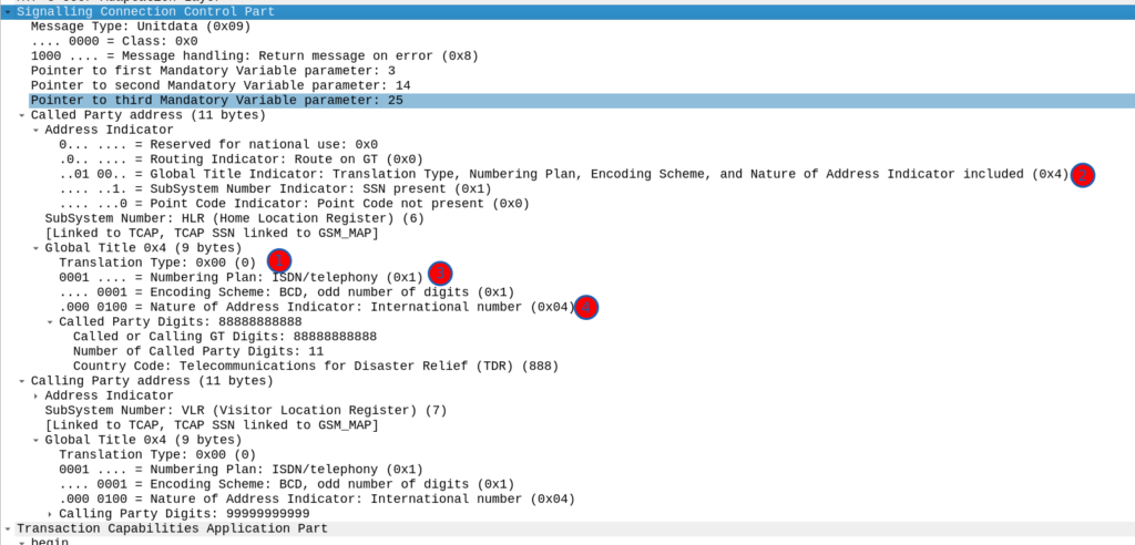
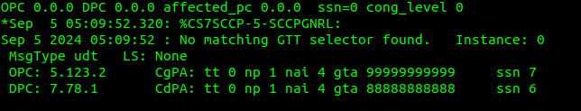
To indicate we’re using SCCP, we set the Signaling Indicator bit in the M3UA / MTP3 message to SCCP:
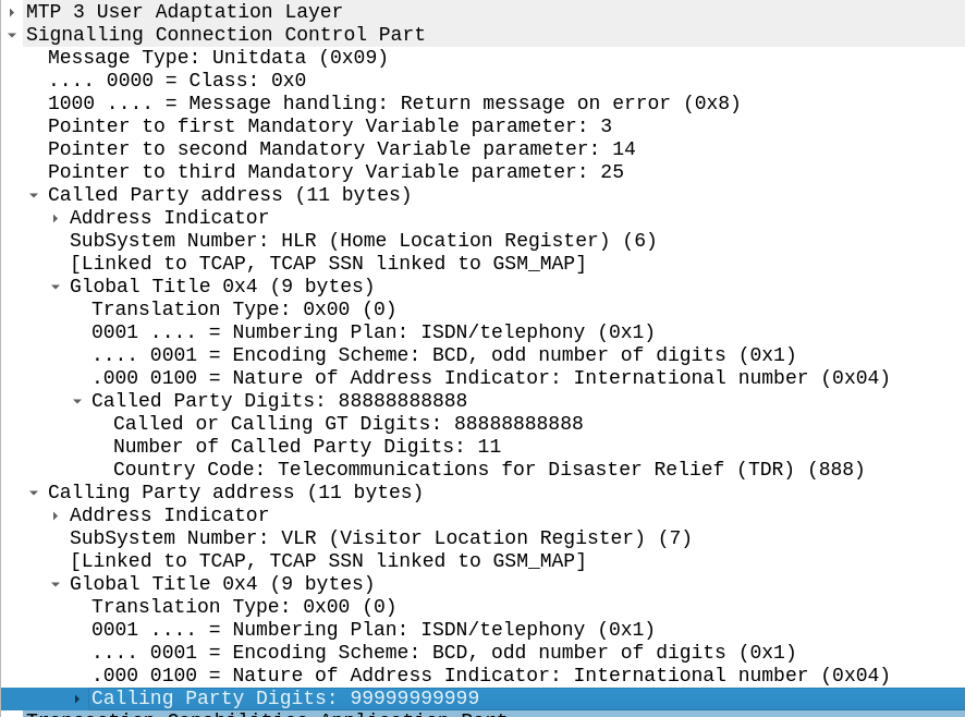
Great, now we can look at our SCCP header.
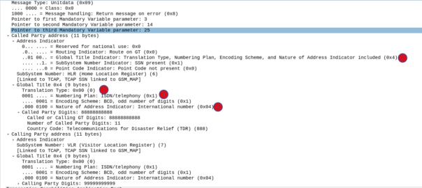
It looks like there’s a lot going on, but we can see the calling and called party (888888888 is called by 9999999999) with the Subsystem number set (888888888 is called for subsystem HLR, from 999999999 which is a VLR).
The closest TCP/IP analogy I can think of here is that of port numbers, there’s still an IP (Point code) but the port number allows us to specify multiple applications that run at a higher layer. This analogy falls down when we consider that the Point Code is generally set to that of your STP, not the final STP.
For this to work, we’ve got to have at least one Signaling Transfer Point in the flow, where we send the request to.
Somewhere (generally at the end of the chain of STPs), an STP is going to perform Global Title Translation.
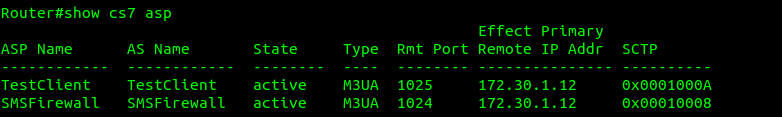
What does this look like? Well let’s have a look at my GT table for the example above, in my lab network, I’ve got two nodes attached (via M3UA but could equally be on MTP3 links), my test MAP client where I’m originating this traffic, and an SMS Firewall, I can see they’re both up here:
Now knowing this I need to setup my SCCP routing for Global Title. In the screenshot above, the Called Party was 888888888 with Subsystem Number 7. Inside the SCCP request, there’s a few other fields, the Translation Type we have set to 0, Global Title Indicator is 4 (route on Global Title), while Numbering Plan Indicator is 1 (ISDN) and Nature of Address Indicator is 4 (International).
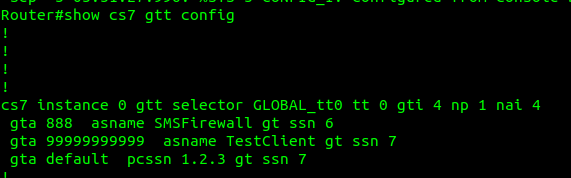
So on my Cisco ITP I define a GTT Selector to target traffic with these values, Translation Type is 0, Global Title Indicator is 4, Number Plan is 1 and the Nature of Address Indicator is 4.
So we’d define a Global Title Translation selector like the one below to match this traffic:
But that’s only matching the group of traffic, it’s not going to match based on the actual SCCP Called Party. So now I need to define a translation for each Global Title address (Called /Calling party) or prefix I want to route, I’ve setup anything starting with 888 to route to the `SMSFirewall` ASP endpoint.
I could stop here and my request addressed to 888888888 would make it to the SMSFirewall ASP, but the response never would, like in all SS7 routing, we need to define the return route translation too, which is what I’ve done for 999999 to route to the TestClient.
Lastly I’ve added a wildcard route, this means if this STP doesn’t know how to resolve a GT address matching the rules in the top line, it’ll forward the request to the STP at point code 1.2.3 – This is how you’d do your connection to an IPX / Signaling exchange.
Debugging this can be a massive pain in the backside, but if you enable logging you can see when GT rules are not matched, like in the example below.
If your network is quiet enough, it’s sometimes easier to just make your rules based on what you observe failing to route.
So with those routes in place, when we send a request with the Global Title called party starting with 8888888 it’s routed to M3UA ASP SMSFirewall, which handles the request, and then sends the response back to the MAPClient M3UA ASP.
A totally complete history and not just something I learned from a fellow phone nerd who’s been around a lot longer than me...
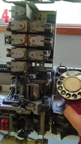
In the early days of telephony voice calls were made by signaling to an operator who would connect your call.
Around the turn of the century the first “automatic” exchanges began to open. This meant that a subscriber could complete their own call, by directly dialing the digits of the party the want to speak to, and getting through, without a human operator “plugging up” the call.
The first type of switches used to provide “automatic” exchange capability were Strowger type switches, they translated the pulses from a rotary dial phone into physical movements on a switch to find and select the line you want.
As it happens I have one of these old switches, here’s what happens when you let go of the dial.
People who were born before touch tone phones can tell you about how you can dial a phone number without using the dial at all. By mashing the hook switch really quickly. If you want to dial a 3 you mash the hook switch 3 times, then wait a second, then to dial a 5 smash the hook switch 5 times, etc, etc.
A quirk of this is that higher numbers, are harder to dial, you just need one pulse of the hook switch in a second to dial a 1, but you need 10 pulses to dial a 0. This means a phone dial that’s running too slow can dial the lower digits, but not the higher digits, as it can’t pulse out the required number of pulses is the time allotted (a smidge over 1 second per digit).
Initially exchanges only connected local calls, but with the introduction of Subscriber Trunk Dialing (STD), subscribers could call from one exchange to another without an operator.
This led to national dialing plans being developed, ensuring uniqueness of numbers across the whole of the phone network, and where possible, lower numbers were used, Australia for example has area codes 02, 03, 07 and 08 (with the majority of the population living in the 02 and 03 area codes).
Now imagine you’re the government owned phone company, tasked with creating a single number for emergency services, 123, 111, etc, etc, are all taken up, as these are the most reliable numbers to dial and were used long ago.
Instead you go to the other end, the UK with 999 and Australia with 000 (911 is a different kettle of fish).
Except in New Zealand.
111 was specifically chosen to be similar to Britain’s 999 service, but NZ has some odd peculiarities.
The NZ dials are identical to the standard dial except for the finger plate label.
With pulse dialing, New Zealand telephones pulse “in reverse” to the rest of the world. Dialing 0 on a phone in the rest of the world, sent ten pulses down the line. But dialing a 0 on a phone in NZ sent one pulse down the line. The same for all the other numbers. The phones weren’t different – Just the labels.
Hence the reason why ‘Emergency’ services were on 111 in NZ (but actually pulsed 999) as the exchanges originated in those days from the UK where 999 was (and still is 999).
In the early years of 111, the telephone equipment was based on British Post Office equipment, except for this unusual orientation. Therefore, dialing 111 on a New Zealand telephone sent three sets of nine pulses to the exchange, exactly the same as the UK’s 999.
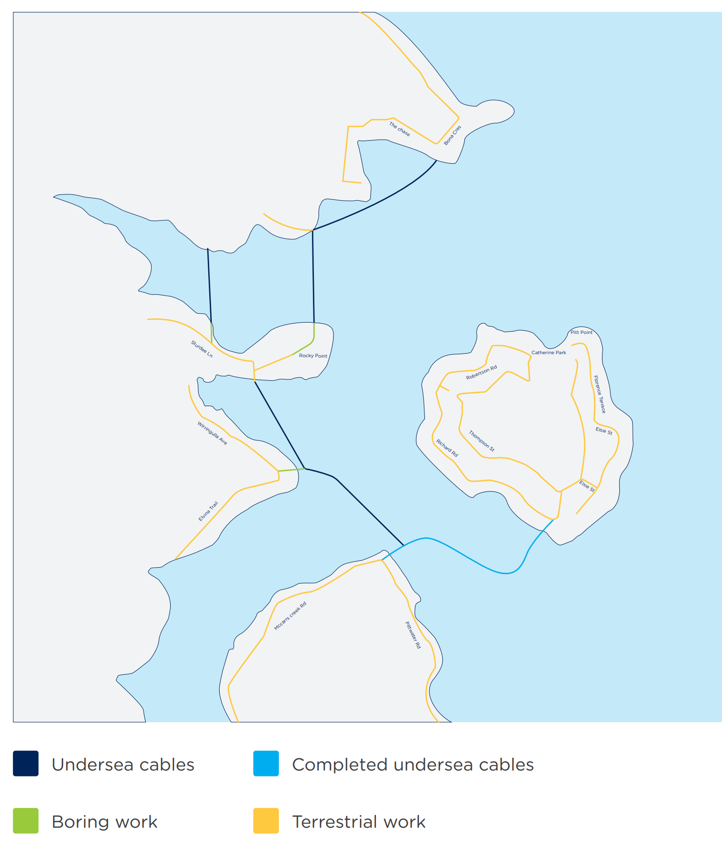
Recently I took a week off work and went hiking around the Hawkesbury river in NSW.
This did not mean I stopped thinking about telecom.
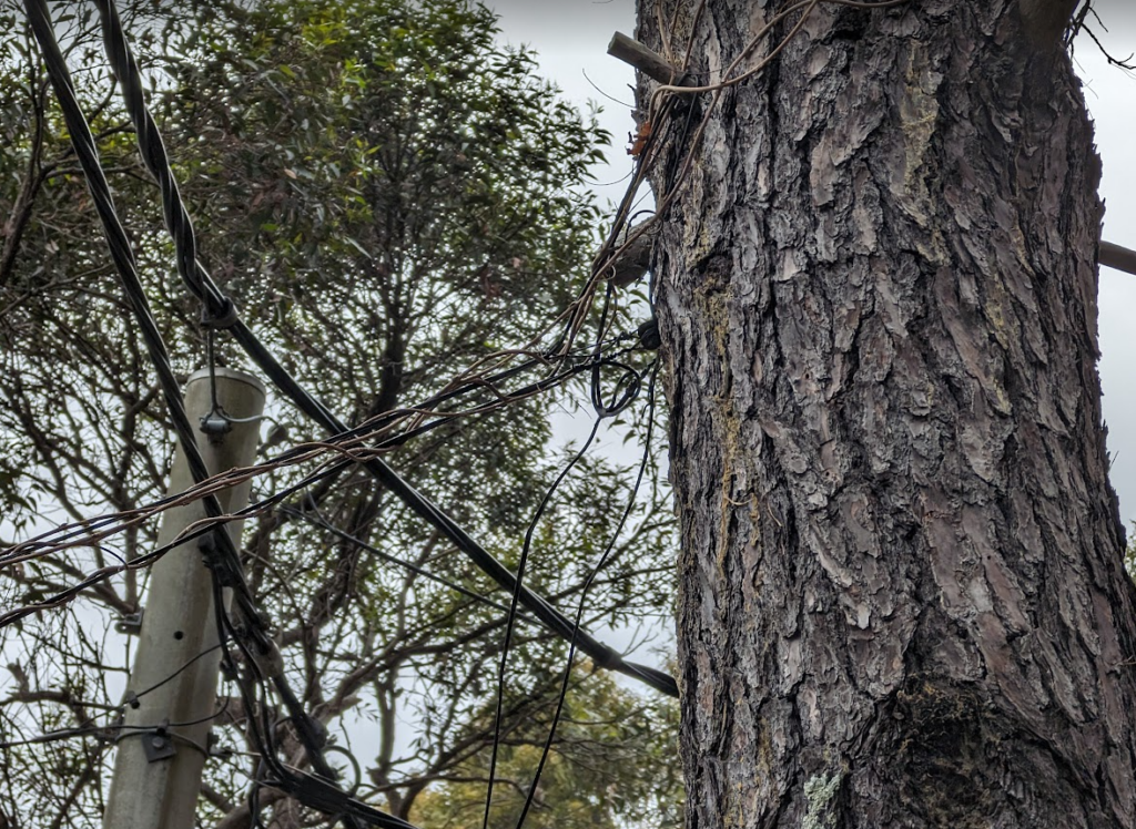
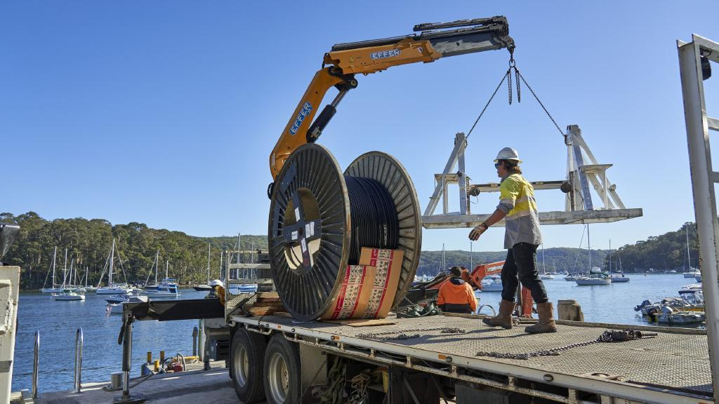
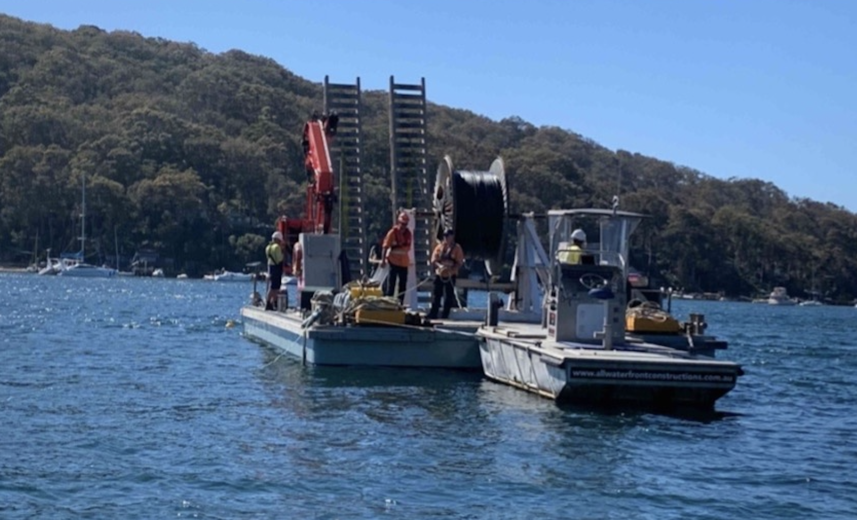
There’s a lot of beautiful bushland and some fancy houses nestled into the area, a good chunk of which are not accessible by road at all, with the only way to access them being by boat or a long hike along a bush track.
No fancy erbium-doped fiber amplifiers here though, just regular GPON laid on the riverbed.
Telstra / Telecom had previously laid a copper 100 pair (seemingly just regular gel filled cable directly on the riverbed without any protection) to service the area, and then aerial distribution along the tracks connecting the homes.
NBNco it seems opted for a slightly safer approach and used Protectorshell articulated pipe to protect the cables in the water / on the beaches.
Strange tree roots – NBN Articulated pipe on the left with the old copper 100 pair on the right
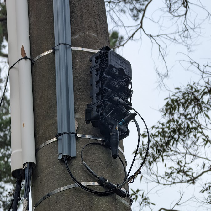
Once the cables land it’s back to regular NBN Aerial fiber runs, with DPUs on the power poles.
Apart from a few interesting catenary runs, and the fact there are no roads, once the fibre lands it’s very much a standard aerial NBN deployment.
There’s some great pics below from the supplier websites and local news site:
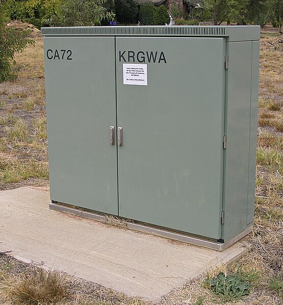
The gray telecom cabinets and pillars can be seen in suburbs across Australia, along rail corridors and even overseas.
But what do they do? What’s the difference between a pillar and a cabinet? Are they still used today? What’s inside? Why are they such an important part of the network?
What are they?
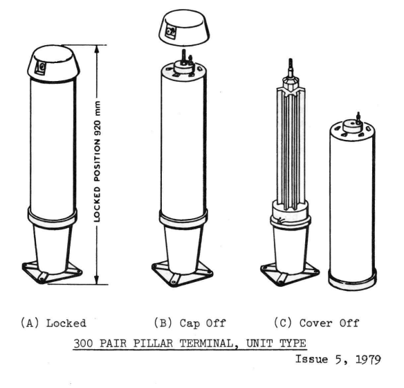
In a nutshell, they’re weatherproof (if properly cared for) enclosures for cross connecting (jumpering) cables.
This means that rather than doing the jumpering / cross connecting services in a dirty pit, a cabinet can be opened and the connection made quickly, in a clean, easily accessed, above ground housing.
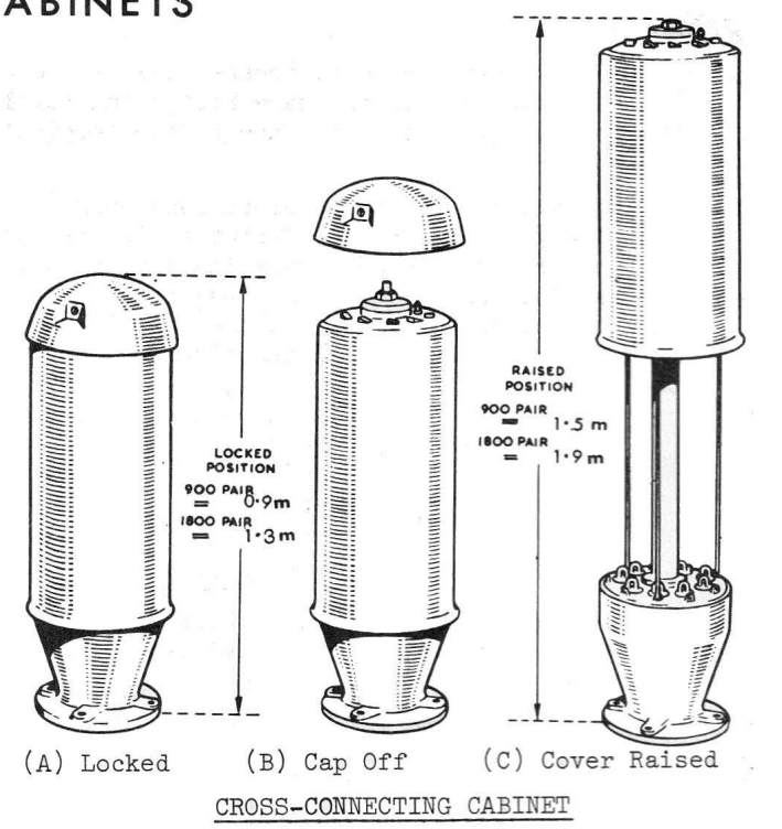
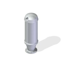
They utilise a really clever design, that was the result of a competitive design process in the 1950s.
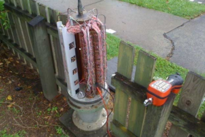
The schrader valve (bike valve) at the top allows the units to remain pressurized, this means in areas subject to flooding or for pressurised cables, the pillar remains water tight ( although the practice of sealing them again with air isn’t very common anymore).
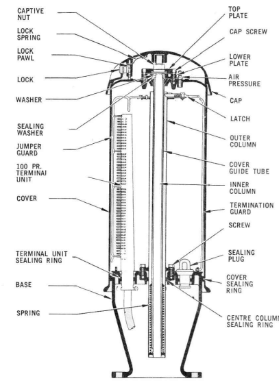
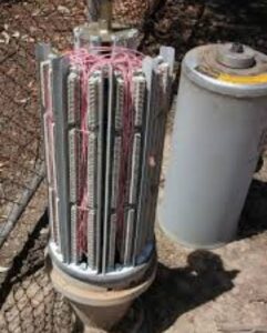
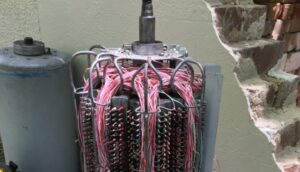
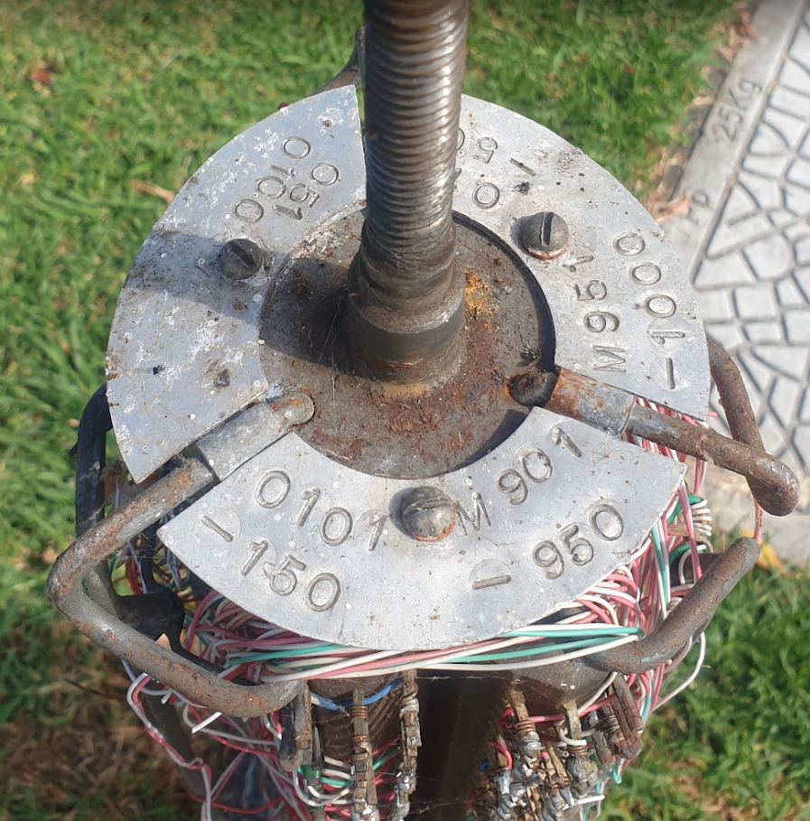
When the aluminum top plate is unlocked and spun off the threaded fitting, the linesworker can unscrew the big nut on top, and lift up the cover, which locks open at the top, revealing the terminal units (either solder tag blocks or Krone blocks) inside the unit.
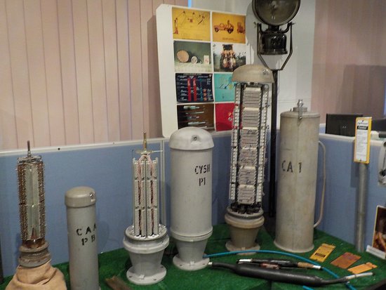
900 pair IDC1800 pair tag block with Loopalines1800 pair with IDC and F-Set1900 pair tag block900 pair in a fenceCable management
Jumpering a service is just a matter of opening up the cabinet, finding the A side and the B side, and running jumper wire through the built in cable management loops from one side to the other.
Each of the Terminal Units is a pre-terminated strip with a few meters of tail, which is fed through the base of the pillar to a nearby pit where they can join 1 to 1, out onto the underground cables, this means the units can be upgraded for additional capacity as needed.
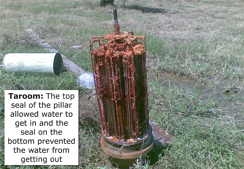
While pressurised they are IP67 rated, but this only goes so far, check out this Telstra photo from Queensland Floods in 2010 from Taroom.
Why were they needed?
Cables are expensive. We want to minimize excess unused pairs and use the existing pairs with maximum flexibility and efficacy
Opening joints costs time, money, and risks disturbing other services. We want to avoid opening joints
Troubleshooting is also time consuming and costly. A convenient test point is needed for isolating where in a cable a fault lies. (Main Cable, Distribution Cable, etc)
Easily use gas/air filled cables, without having to constantly open and reseal cables them to splice in new joins / jumpers
Cabinet vs Pillar
Cabinets and Pillars look the same, but the hints as to their purpose are in their location and what’s sprayed on them in faded paint.
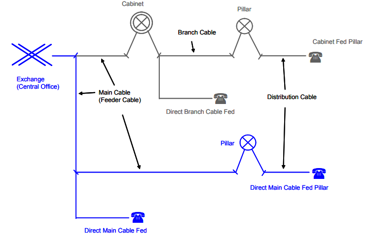
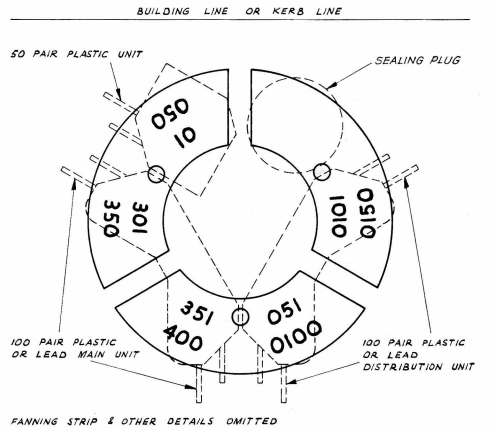
Pillars are used for cross-connecting main cables (“M” Pair from the exchange) with distribution cables (to subscribers “O” pairs which run down the street to the pit in the front of your house).
Pillars are generally stenciled with a “P” and an number, or just the DA (Distribution Area) number.
Cabinet are a more flexible setup where you can connect cables between Pillars, akin to a root & branch approach.
Cabinets cross connect Main Cables (“M” pair to the exchange), with Branch Cables (“B” Pair from the Cabinet to Pillar) and Distribution cables (“O” pair to the customer).
Cabinets are stenciled with the prefix “CA” and a number, and exist in the 900 and 1800 pair variants, where one is just taller than the other.
The blue example is direct from the Main Cable to the Pillar, while Cabinets are used in the black example.
This means the distribution can go via a Cabinet to the Pillar to the Customer, as shown in the top /grey lines in the diagram.
Exchange Main Cables (Main Cables / M-Pairs) go to Cabinets
Cabinets connect to Pillars (Branch Cables / B-Pairs)
Pillars connect (Distribution Cables / O-Pairs) that run through the pits outside houses
Inside the Openable Joint in the pit is used to connect the lead in cable from a subscriber’s premises
Alternatively, the Cabinet may be bypassed and a direct cable goes between the Exchange and the Pillar, in that scenario it looks like the one show in blue lines on the diagram.
Exchange Main Cables (Main Cables / M-Pairs) go to Pillar
Pillars connect (Distribution Cables / O-Pairs) that run through the pits outside houses
Inside the Openable Joint in the pit is used to connect the lead in cable from a subscriber’s premises
Display of 300, 900 and 1800 pair pillars and cabinets at the former Telstra Museum in Hawthorn
The Cabinet to Pillar model fell out of favor due to its increased complexity. While it was cheaper to deploy the network using cabinets that cascaded down to feed pillars (you would only have to install enough cable for the “here and now” and could add additional Main & Branch cables as needed in a targeted manner) the move to outsourced lineswork for Telecom found that any increased complexity, led to additional operational cost that outweighed the capital savings
Use in the “Modern” Copper Customer Access Network
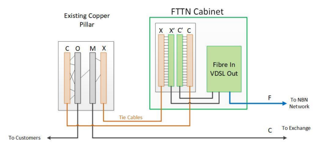
Pillars are still used in areas of Australia where NBNco have deployed Fibre to the Node.
This means a customer with a traditional POTS line (M-Pair from the Exchange, C-Pair from the Cabinet to the Pillar, O-Pair from the Pillar to the Pit, and then the lead-in into their property) has the O-Pair and C-Pair buzzed out on the pillar, and then routed through the X-Pair and the C-Pair on the Node.
This puts the DSLAM in the Alcatel ISAM inline with the customer’s existing copper loop to the Exchange. The main cable comes from the exchange onto the M-Pair blocks in the Pillar, is jumpered onto the X-Pairs which go through the DSLAM, and come out as C-Pairs back onto the pillar. The C-Pair is then jumpered back to the Customer’s O-Pair and bingo, the FTTN cabinet is inline with the copper loop.
However as the PSTN services get dropped, the Main / M-Pair to the exchange can eventually be removed and the cables removed, meaning the connection just goes from the C pair for VDSL out into the O pair to the customer.
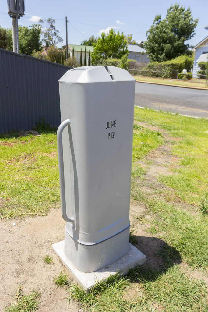
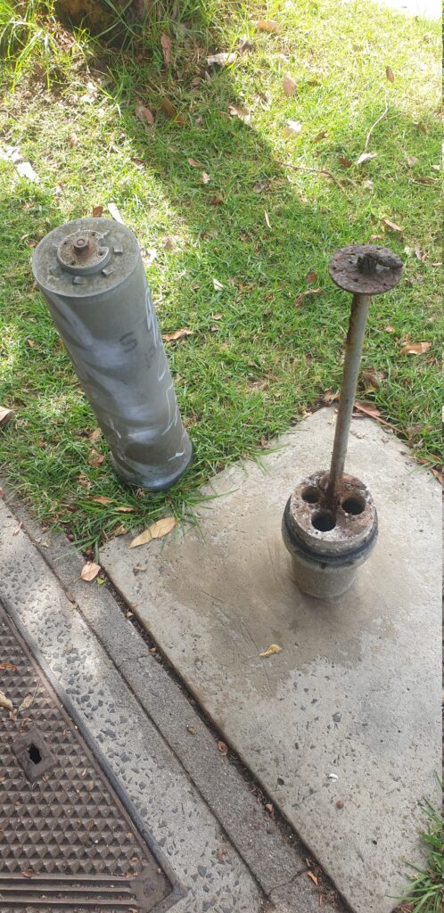
As part of the NBN migration some pillars were upgraded to include IDC / Punch Down blocks, and a rectangular version of the pillar was introduced.
NBN pillar
Oddly, these rectangular covers, do not have rectangular units inside, but rather cylindrical ones, just like the pillars of old.
This does fix the missing lids issue – The lid is captive, but I’m not sure what other design improvements this introduces – if anyone has the insight I’d be keen to hear it!
A few years ago, I was out with a friend (who knows telecom history like no one else) who pointed at a patch of grass and some concrete and said “There’s an underground exchange under there”.
Being the telecommunications nerd that I am, I had a lot of follow up questions, and a very strong desire to see inside, but first, I’m going to bore you with some history.
I’ve written about RIMs – Remote Integrated Multiplexers before, but here’s the summary:
In the early ’90s, Australia was growing. Areas that had been agricultural or farmland were now being converted into housing estates and industrial parks, and they all wanted phone lines. While the planners at Telecom Australia had generally been able to cater for growth, suddenly plonking 400 homes in what once was a paddock presented a problem.
There were traditional ways to solve this of course; expanding the capacity at the exchange in the nearest town, trenching larger conduits, running 600 pair cables from the exchange to the housing estate, and distributing this around the estate, but this was the go-go-nineties, and Alcatel had a solution, the Remote Integrated Multiplexer, or RIM.
A RIM is essentially a stack of line cards in a cabinet by the side of the road, typically fed by one or more E1 circuits. Now Telecom Australia didn’t need to upgrade exchanges, trench new conduits or lay vast quantities of costly copper – Instead they could meet this demand with a green cabinet on the nature strip.
This was a practical and quick solution to increase capacity in these areas, and this actually worked quite well; RIMs served many Australian housing estates until the copper switch off, many having been upgraded with “top-hats” to provide DSLAM services for these subscribers as well, or CMUX being the evolved version. There’s still RIMs that are alive in the CAN today, in areas serviced by NBN’s Fixed Wireless product, it’s not uncommon to see them still whirring away.
A typical RIM cabinet
But in some areas planning engineers realised some locations may not be suitable for a big green cabinet, for this they developed the “Underground CAN Equipment Housing” (UCEH). Designed as a solution for sensitive areas or locations where above ground housing of RIMs would not be suitable – which translated to areas council would not them put their big green boxes on their nature strips.
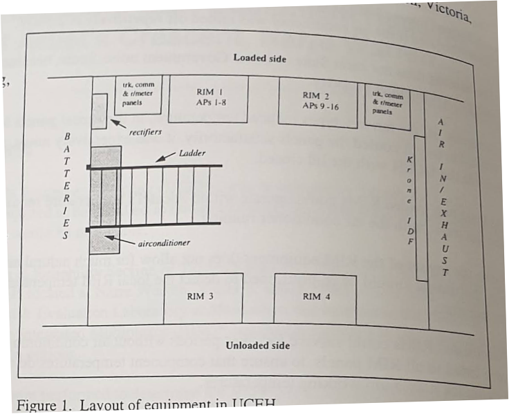
So in Narre Warren in Melbourne’s outer suburbs Telecom Research Labs staff built the first underground bunker to house the exchange equipment, line cards, a distribution frame and batteries – a scaled down exchange capable of serving 480 lines, built underground.
Naturally, an underground enclosure faced some issues, cooling and humidity being the big two.
The AC systems used to address this were kind of clunky, and while the underground exchanges were not as visually noisy as a street cabinet, they were audibly noisy, to the point you probably wouldn’t want to live next to one.
Sadly, for underground exchange enthusiasts such as myself, by 1996, OH&S classified these spaces as “Confined Spaces”, which made accessing them onerous, and it was decided that new facilities like this one would only be dug if there were no other options.
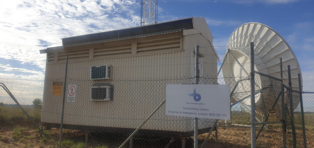
This wasn’t Telecom Australia’s first foray into underground equipment shelters, some of the Microwave sites in the desert built by telecom put the active equipment in underground enclosures covered over by a sea freight container with all the passive gear.
Some of these sites still exist today, and I was lucky enough to see inside one, and let’s face it, if you’ve read this far you want to see what it looks like!
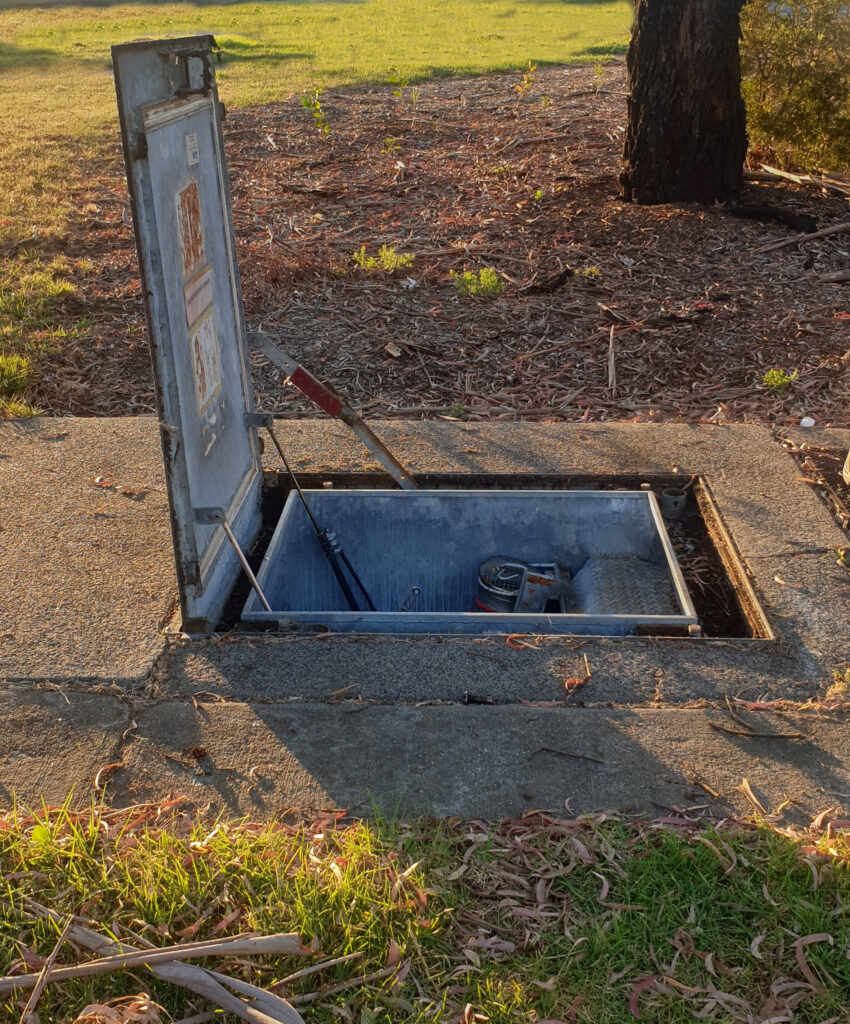
A large steel plate sunk into a concrete plinth doesn’t give away what sits below it.
A gentle pull and the door lifts open with a satisfying “woosh” – assisted by hydraulics that still seem to be working.
The power to the site has clearly been off for some time, but the sealed underground exchange is in surprisingly good condition, except for the musky smell of old electronics, which to be honest goes for any network site.
There’s an exhaust fan with a vent hose that hogs a good chunk of the ladder space, which feels very much like an afterthought.
Inside is pretty dark, to be expected I guess what with being underground, and not powered.
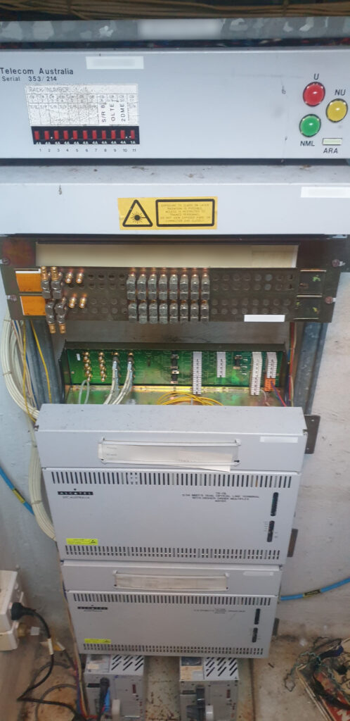
Inside is the power system (well, the rectifiers – the batteries were housed in a pit at the end of the UECH entrance hatch, so inside there are no batteries), a distribution frame (MDF / IDF), and the Alcatel cabinets that are the heart of the RIM.
From the log books it appeared no one had accessed this in a very long time, but no water had leaked in, and all the equipment was still there, albeit powered off.
I’ve no idea how many time capsules like this still exist in the network today, but keep your eyes peeled and you might just spot one yourself!
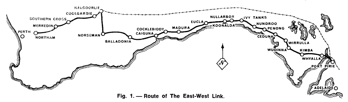
On July 9, 1970 a $10 million dollar program to link Australia from East to West via Microwave was officially opened. Spanning over 2,400 kilometres, it connected Northam (to the east of Perth) to Port Pirie (north of Adelaide) and thus connected the automated telephone networks of Australia’s Eastern States and Western States together, to enable users to dial each other and share video live, across the country, for the first time.
In 1877, long before road and rail lines, the first telegraph line – a single iron wire, was spanned across the Nullabor to link Australia’s Eastern states with Western Australia.
By 1930 an open-wire voice link had been established between the two sides of the continent. This was open-wire circuit was upgraded a rebuilt several times, to finally top out at 140 channels, but by the 1960s Australian Post Office (APO) engineers knew a higher bandwidth (broadband carrier) system was required if ever Standard Trunk Dialling (STD) was to be implemented so someone in Perth could dial someone in Sydney without going via an operator.
A few years earlier Melbourne and Sydney were linked via a 600 kilometre long coaxial cable route, so API engineers spent months in the Nullarbor desert surveying the soil conditions and came to the conclusion that a coaxial cable (like the recently opened Melbourne to Sydney Coaxial cable) was possible, but would be very difficult to achieve.
Instead, in 1966, Alan Hume, the Postmaster-General, announced that the decision had been made to construct a network of Microwave relay stations to span from South Australia to Western Australia.
In the 1930s microwave communications had spanned the English channel, by 1951 AT&T’s Long Lines microwave network had opened, spanning the continental United States. So by the 1960’s Microwave transmission networks were commonplace throughout Europe and the US and was thought to be fairly well understood.
But soon APO engineers soon realised that the unique terrain of the desert and the weather conditions of the Nullabor, had significant impacts on the transmission of Radio Waves. Again Research Labs staff went back to spend months in the desert measuring signal strength between test sites to better understand how the harsh desert environment would impact the transmission in order to overcome these impediments.
The length of the link was one of the longest ever attempted, longer than the distance from London to Moscow,
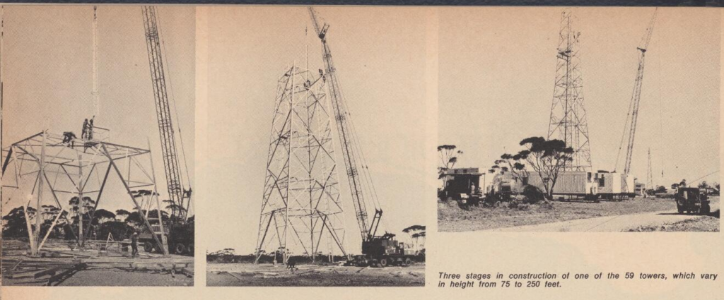
In the end it was decided that 59 towers with heights from 22 meters to 76 meters were to be built, topped off with 3.6m tall microwave dishes for relaying the messages between towers.
The towers themselves were to be built in a zig-zag pattern, to prevent overshooting microwave signals from interfering with signals for the next station in the chain.
Due to the remote nature of the repeater sites, for 43 of the 59 repeater sites had to be fully self sufficient in terms of power.
Initial planning saw the power requirements of the repeater sites to be limited to 500 watts, APO engineers looked at the available wind patterns and determined that combined with batteries, wind generators could keep these sites online year round, without the need for additional power sources. Unfortunately this 500 watt power consumption target quickly tripled, and diesel generators were added to make up any shortfall on calm days.
The addition of the Diesel gensets did not in any way reduce the need to conserve power – the more Diesel consumed, the more trips across the desert to refuel the diesel generators would be required, so the constant need to keep power to a minimum was one of the key restraints in the project.
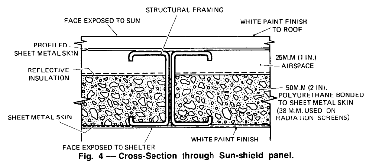
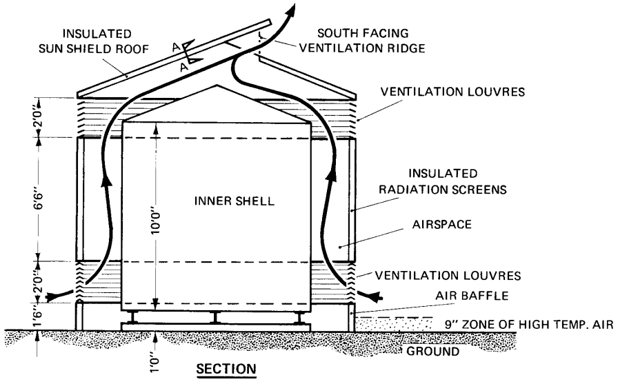
The designs of these huts were reused after the project for extreme temperature equipment housings, including one reused by Broadcast Australia seen in Marble Barr – The hottest town in Australia.
Active cooling systems (Like Air Conditioning) were out of the question due to being too power hungry. APO engineers knew that the more efficient equipment they could use, the less heat they would produce, and the more efficient the system would be, so solid state (transistorised devices) were selected for the 2Ghz transmission equipment, instead of valves which would have been more power-hungry and produced more heat.
The reduced power requirement of the fully transistorized radio equipment meant that wind-supplied driven generators could provide satisfactory amounts of power provided that the wind characteristics of the site were suitable.
THE TELECOMMUNICATION JOURNAL OF AUSTRALIA / Volume 21 / Issue 21 / February 1971
So forced to use passive cooling methods, the engineers on the project designed the repeater huts to cleverly utilize ventilation and the orientation of the huts to keep them as cool as possible.
Construction was rough, but in just under 2 years the teams had constructed all 59 towers and the associated equipment huts to span the desert.
Average time to construct a tower was 6 daysMenzies, built in the 1980s as an additional spurTower in Kalgoorlie
When the system first opened for service in July 1970, live TV programs could be simulcast on both sides of the country, for the first time, and someone in Perth could pick up the phone and call someone in Melbourne directly (previously this would have gone through an operator).
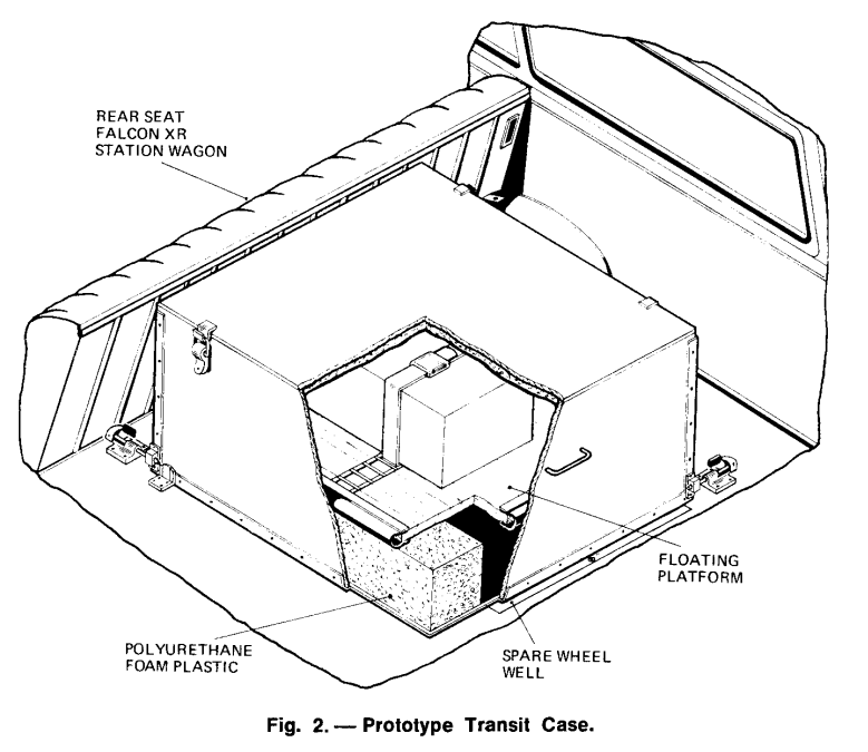
PMG Engineers designed a case to transport the fragile equipment spares – That resided in the back of a Falcon XR Station Wagon
The system offered 1+1 redundancy, and capacity for 600 circuits, split across up to 6 radio bearers, and a bearer could be dedicated at times to support TV transmissions, carried on 5 watt (2 watt when modulated) carriers, operating at 1.9 to 2.3Ghz.
By linking the two sides of Australia, Telecom opened up the ability to have a single time source distributed across the country, the station in Lyndhurst in Victoria, created the 100 “microseconds” signal generated by a VNG, that was carrier across the link.
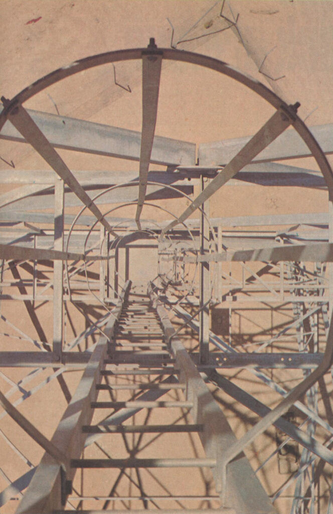
Looking down one of the towers
Unlike AT&T’s Long Lines network, which lasted until after MCI, deregulation and the breakup off the Bell System, the East-West link didn’t last all that long.
By 1981, Telecom Australia (No longer APO) had installed their first experimental optic fibre cable between Clayton and Springvale, and fibre quickly became the preferred method for broadband carrier circuits between exchanges.
By 1987, Melbourne and Sydney were linked by fibre, and the benefits of fibre were starting to be seen more broadly, and by 1989, just under 20 years since the original East-West Microwave system opened, Telecom Australia completed a 2373 kilometre long / 14 fibre cable from Perth to Adelaide, and Optus followed in 1993.
This effectively made the microwave system redundant. Fibre provided a higher bandwidth, more reliable service, that was far cheaper to operate due to decreased power requirements. And so piece by piece microwave hops were replaced with fibre optic cables.
I’m not clear on which was the last link to be switched off (If you do know please leave a comment or drop me a message), but eventually at some point in the late 1980s or early 1990s, the system was decommissioned.
Many of the towers still stand today and carry microwave equipment on them, but it is a far cry from what was installed in the late 1960s.
If you’re typing on a full size keyboard there’s a good chance that to your right, there’s a number pad.
The number 5 is in the middle – That’s to be expected, but is 1 in the top left or bottom left?
Being derived from an adding machine keypad, the number pad on a keyboard has a 1 will be in the bottom left, however in the 1950s when telephone keypads were being introduced, only folks who worked in accounting had adding machines.
So when it came time to work out the best layout, the result we have today was a determined through a stack of research and testing by Human Factors Engineering Department of Bell Labs who studied the most efficient layout of keys, and tested focus groups to find the layout that provided the best level of speed and accuracy.
That landed with the 1 in the top left, and that’s what we still have today.
Oddly ATM and Card terminals opted to use the telephone layout, rather than the adding machine layout, while number pads use the adding machine layout.
On the rare occasions I’m not tied to my desk, I’m out for a long run along some back roads somewhere.
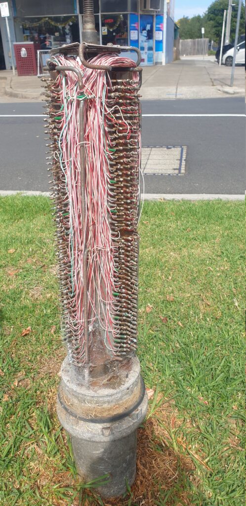
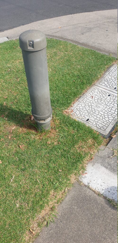
Every now and then I come across these tiny telecom pillars for cross-connection (and don’t shoot at them) – I mostly find them around the edges of distribution areas. I had some recollection that these were originally for trunk lines between exchanges (maybe there was some truth to this?), but some digging in old docs show these were just for interconnecting main or branch cables with distribution cables, in areas where the 600 and 1200 pair pillars / cabinets would be overkill.
They’re built like the 900/1800 pair cabinets, but just scaled down versions, supporting 1x 100 pair main cable, 1x 100 pair distribution cables and 2x 50 pair distribution cables.
It seems like these were largely decomed when NBN took over, leaving most with a big X sprayed on them.
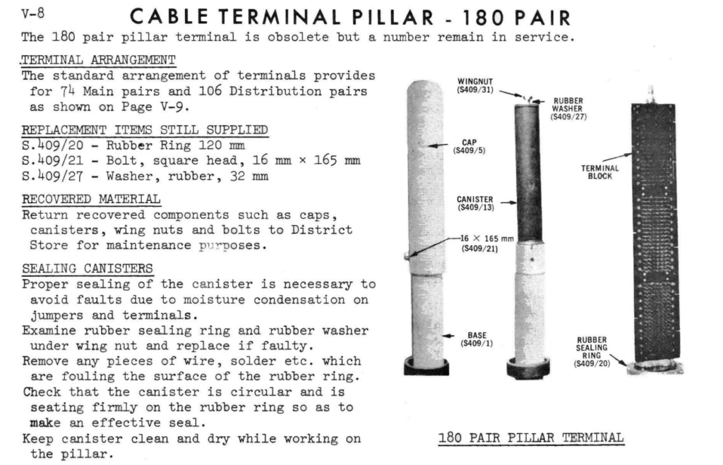
While I was looking through the docs I also found reference to a 180 pair pillar, which looked very similar, but I’ve yet to see any of them left in the wild. Better keep running ’till I find one!
It’s 1986 and you’ve got a 31 tons of copper, in the form of a giant 46 meter tall statue, that’s looking a bit worse for wear.
The Statue of Liberty has had water pooling in some areas, causing areas of her copper skin to corrode, and in some cases wearing all the way through.
On the other side of the iron curtain (it’s still up after all) there are probably quite a number of folks experienced in looking after giant statues, but alas, you’re the US National Parks Service and seeking help from the Soviets is probably a bad look.
The statue is made of Copper, and who knows more about copper than the phone company, with a vast, vast network of copper lines spanning the country?
So the National Parks Service called upon Bell Labs to help.
The Bell Labs’ chemists assigned to the project quickly pointed out that just replacing the corroded copper with new copper would hardly blend in – You’d have the shiny brown copper colour in the new sections, which wouldn’t match the verdigris that occurs through the oxidation of the copper, which would take years to form. (When she was delivered, the statue had a copper colour like you’d see in Copper piping, not the green patina we see today.)
Bell Labs staff looked at artificially creating the patina with acid solutions, to speed up the process to match the new copper with the old, but it was found it may cause structural weak points.
John Franey who was a technical assistant working at Bell Labs’ Murray Hill laboratories must have looked up at the roof of their buildings, constructed in 1941, and thought “Well that looks pretty close…”, so the naturally patinaed roof of Bell Lab’s New Jersey campus was peeled up and sent off for patching the statue.
Modern day roof at Murray Hill now with the verdigris that’s had 40 years to form
Murray Hill got a shiny new copper roof to replace the old green one they’d just given up, and the particles of copper corrosion scraped off the dismantled roof of a Bell Labs were mixed with acetone into a special spray used as concealer on the statue’s skin.
In exchange, Bell Labs staff were given some of the copper plates removed from the statue, so they could study the natural corrosion process in copper, in various weather conditions, which in turn would lead to a better understanding of how to build and maintain their copper plant.
Relocating vast numbers of subscriber lines is something to be avoided.
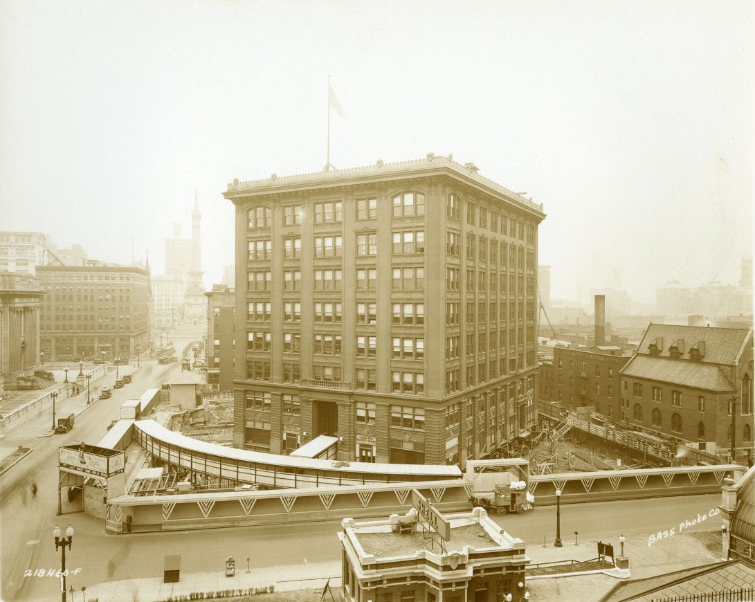
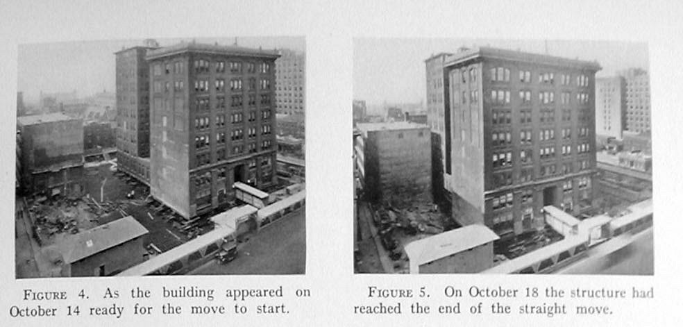
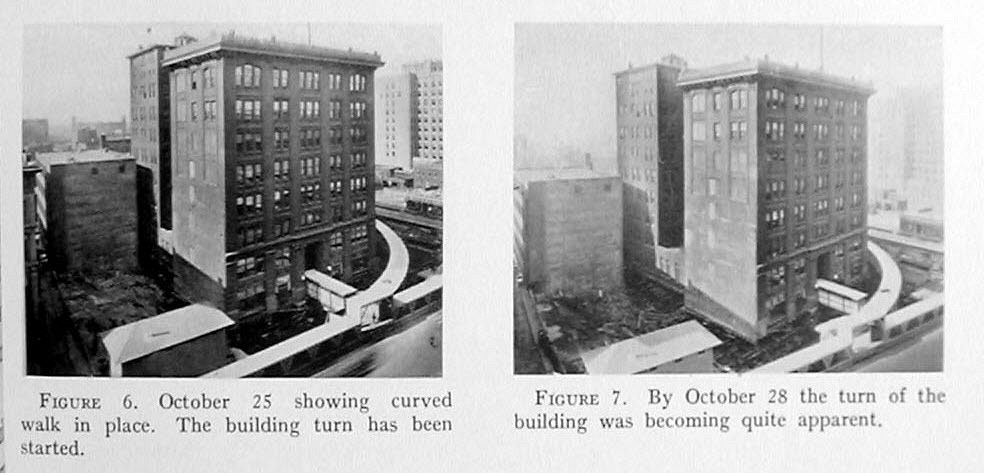
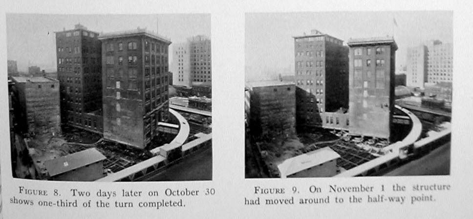
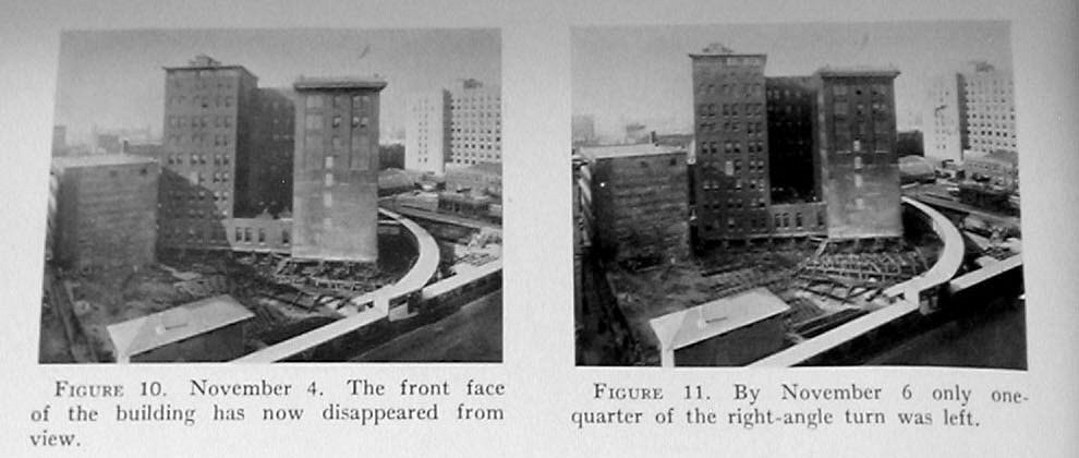
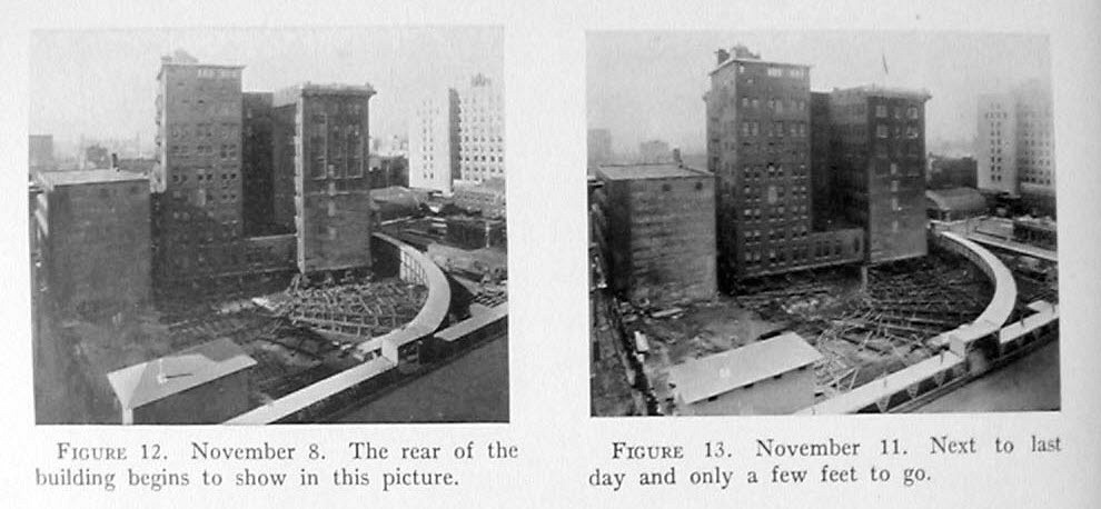
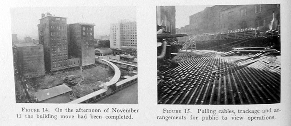
In 1929 Indiana Bell realized they needed a larger telephone exchange (“CO” to use the US term) to meet growing demand, and while there was vacant land around the current building, it wasn’t large enough to build on with the current building slap-dab in the middle of it.
So rather than relocate the subscriber lines to a newly built exchange, they just moved the exchange to the rear of the block, to free up space to build a larger one.
Over a 4 week period engineers shifted the working, 8 story steel and brick telephone exchange, still fully staffed, around to the other side of the block, without any interruptions to the subscribers served from the exchange.
For example if you were on the GArfield exchange (GA) you’d give your number as GA 1234 or GArfield 1234, to dial this the GA would just be converted into numbers based on the dial, so GA = 42 1234.
The Bell system had wanted to do away with this for a long time – it’s inflexibility meant digits that spelled out the prefix of common place names were filled up, while others were almost unused, and was not conducive to the growth patterns of telephone systems. Letters alone limited the dialing plan to 540 combinations for the area code, for 186 million Americans at the time, while moving to all-numbers opened up for use the 0 and 1 positions on the dial (which don’t have letters associated with them), expanding the pool.
The North American Numbering Plan (NANP) had been divided by AT&T in the 1940s and from 1951 onwards was being rolled out across the bell system, so it shouldn’t have come as any great surprise that in May of 1962 Pacific Telephone and Telegraph, like many other Bell system companies, made the announcement instead of exchange names, there would be a 3 digit exchange code / area code, followed by 4 more digits for the local subscriber, what it called “All-number dialing”.
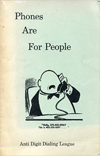
This is where our story would end if it weren’t for some outcry of locals regarding the loss of their beloved exchange codes. Letters to the editor of local newspapers led to polling by the San Francisco Chronicle revealing two-thirds of their readers opposed to all-number dialing, which led to one man – Carl V May, taking out an advertisement in the the local newspapers with a simple one line statement and address,
Join the Anti-Digit Dialing League
P.O. Box 996, Sausalito, Calif
The ad received over 3,500 responses, and a sizable following for the group sprang up practically overnight, united in their opposition to the loss of the exchange letters and the “creeping numeralism” being pushed upon them.
These people are systematically trying to destroy the use of memory. They tell you to ‘write it down,’ not memorize it. Try writing a telephone number down in a dark booth while groping for a pencil, searching in an obsolete phone book and gasping for breath. And all this in the name of efficiency ! Engineers have a terrible intellectual weakness. ‘If it fits the machine,’ they say, ‘then it ought to fit people.’ This is something that bothers me very much: absentmindedness about people.
To be clear, automation and the removal of switchboard operators for local calls (Direct Digit Dialing (DDD)) (“Subscriber Trunk Dialing” or “STD” as it’s known in the UK and Australia) had happened already, so this wasn’t about people losing their jobs, but rather Citizens wanting to keep the letters of the places their dialing. Nor were phone numbers themselves changing due to All-Digit-Dialing, if your number was GA 1234 you’d still dial 42 1234 to get there, it would just be printed as 42 1234 instead of GA 1234 in the phone books.
A steady stream of telephone customers–“mainly from the Valley,” said a Times account of the local hearings–complained that ANC was dehumanizing, violated tradition, eliminated a sense of community, increased dialing errors, made phone numbers more difficult to remember and ran up phone bills, because people no longer knew where they were calling.
ADDL’s support continued to grow, badges appeared and a legal challenge was mounted against the phone company to prevent this, and a restraining order was issued to halt the project, and the Public Utilities Commission had to go through 3,200 pages of testimony from hearings in Los Angeles and San Francisco on the impact of the All-Number-Calling system.
The 25 cent lapel pin available for members of the ADDL
Comedian Alan Sherman wrote a song called “The Let’s All Call Up A.T & T And Protest To The President March” on his 1963 album “My Son, The Celebrity”, which hasn’t aged well…
But progress marched on, the restraining order was quashed and by 1964 NANP rolled on, and all-digit dialing continued to be rolled out across the rest of North America.
And as quickly as it appeared, the ADDL was gone.
NANP continued and phone numbers were changed and expanded several times since then, but never with resistance as strong as that of the ADDL.
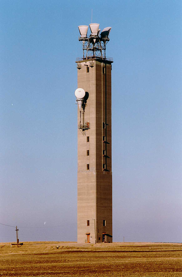
So this is the story of how in the 1960s AT&T’s Bell Labs bet on millimeter waves being the communications medium of the future, 60 years before 5G’s millimeter wave hype.
AT&T’s Bell Labs were working with millimeter waves aka “mmWave” in 5G speak, way back in the 1960s, but using waveguides instead of air as the transmission medium.
AT&T saw the vast amounts of bandwidth available in these bands, and were keen to utilize it. So does history repeat? Are there lessons in here about cursed mmWave bands?
At the time, AT&T’s Long Lines network operated a vast point-to-point Microwave network, spanning across the United States. It operated from 3.7Ghz to 4.2Ghz capacity planners and engineers knew, even with the best multiplexing, you were limited to how many channels you could cram into 500Mhz of space, so Bell Labs started looking for solutions.
Almost from the first, however, the possibility of obtaining low attenuations from the use of circular-electric waves, carrying with it, at the same time, the possibility of extremely high frequencies and accordingly vastly wider bands of frequencies appeared as a fabulous El Dorado always beckoning us onward.
Initially Bell Labs researchers looked at higher frequencies for these wireless links, but after experimenting with using centimeter wavelengths through the air and the issues with attenuation from rain and water vapour, more research was done and Bell Labs decided to use waveguides as the transmission medium for these millimeter wave transmissions, instead of transmitting through the air.
An exploratory development effort was begun in 1959 on a system utilizing 2-inch waveguide and travelling-wave-tube repeater, but was abandoned in 1962 because of TWT cost and reliability problems and because the capacity exceeded then-current Bell System needs.
Thanks to the recent development of IMPATT diodes and Solid-State devices, it was not abandoned for long, and research was picked up again in 1962. At the time Bell Labs didn’t need the additional capacity, nor did they know when it would be commercially viable to start using millimeter waveguide in the field, but like the 5G operators today, Bell Labs staff had seen the massive amounts of bandwidth available at these higher frequencies, and were looking to exploit it.
The idea at Bell Labs was to send information through such waves not by wires or broadcast towers but by means of the circular waveguide, which had been developed down in Holmdel. “A specially designed hollow pipe,” as Fisk defined it, the waveguide was just a few inches in diameter, and lined inside with a special material that would allow it to carry very high-frequency millimeter radio wave signals.
Around the same time the first MASERS were coming onto the market, and light (free space optics) was being considered instead of electrical energy as a transmission medium. Test shooting lasers through the air highlighted the high optic losses in air, showing this wasn’t practical as a transmission method. While optic fibres existed at the time their losses were so high as to make transmitting anything over a few meters impractical.
All the millimeter wave transmission in waveguide research culminated in the creation of the WT4 system, in the late 1970s.
A 60mm waveguide was used
Advertisement from the April 12, 1971 issue of Time magazine
Using two levels of Phase-Shift keying they were able to provide 238k concurrent calls of capacity, which they calculated could be doubled by moving to four levels of PSK.
On a 14km test system (Bell labs used SI units), they calculated they had the ability to carry almost half a million concurrent voice calls, and with 274 Mbps of bandwidth (DS-4), which for the 1970s was no mean feat.
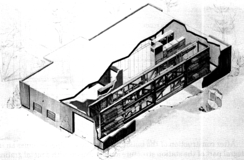
Artist’s impression of a repeater station
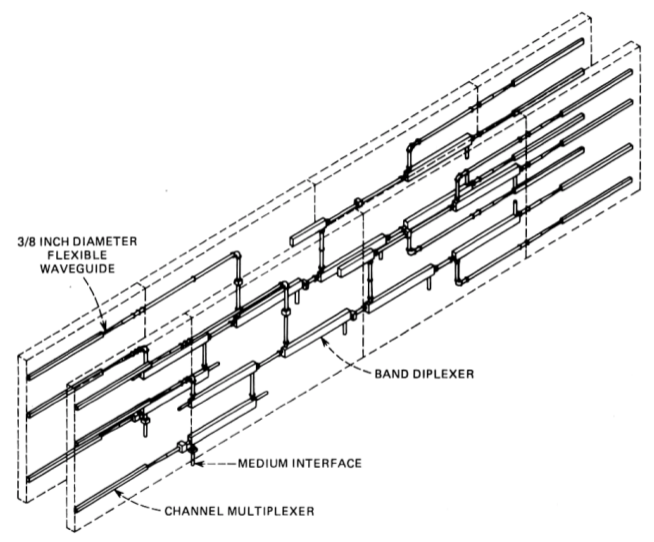
Channelisation was achieved through the use of giant filters of all different types and flavours, to break the test system up into 124 channels (59 in each direction + protection) on the frequencies showing the lowest-losses in experimentation.
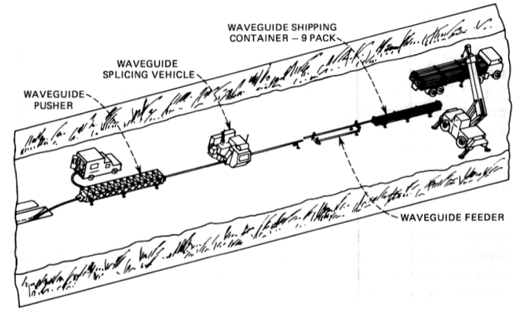
AT&T had historically installed cables, but unlike cables, Waveguides can’t bend, so are more akin to installing water or gas pipes.
This meant the installation of the waveguides into the field leveraged processes from the pipeline industry that were adopted for installation of the waveguides.
“Push sites” selected where a steel sheath (which essentially equated to lengths of hollow steel pipe) could be pushed in under the surface of the earth, with extra pipe welded onto the end as it was pushed along.
This created a clear, straight, conduit for the waveguide to be installed. Due to the fragility of the waveguides themselves, they were laid within the pipe on roller bearings to support the waveguide and to help it slide inside the steel sheath.
In tests AT&T were pushing almost 2.5 Km of waveguide in from one site, with extra lengths of waveguide (9m lengths) being joined by the special “waveguide splicing vehicle” and pushed into the sheath.
Repeater stations were equally tricky, Luckily the WT4 system only required repeater stations at intervals up to 60Km, although when going over hilly terrain, the bends in the waveguide increased losses, so would require repeaters at shorter intervals (~50Km). The inability to bend the cables required a tunnel under each repeater station, through which the waveguides would run, with the repeaters tapping off the waveguides below, via a network of filters. Like the microwave network, some of the repeater stations were equipped to add/drop channels, allowing local traffic to be added/dropped off mid-span. The system was using the new (at the time) Solid State components, but to increase reliability the electronics were encased in airtight dry nitrogen enclosures.
As the WT4 system and its finicky waveguides was being perfected in the 1970s, Corning, a company then known for glass manufacturing, was able to demonstrate that by removing impurities in the glass, optical fibres could be produced with losses of 17 dB per kilometer. Shortly after they got it down to 4 dB per kilometer, and these values kept falling. While early fibre optics were not without their challenges, fibre could be installed in existing conduits, without specialised pipe-pushing and welding equipment, and at a much lower cost per meter.
While WT4 provided bandwidth in numbers unseen before, it’s high cost to deploy and many limitations saw it fade away into the annals of history.
Even in the 1960s Bell Labs staff knew the case for mmWave wasn’t yet financially viable, but built it for a future that didn’t come the way they expected.
So what can this 60 year old tale of engineering teach us?
Bell Labs were pinning their hopes on mmWave to provide limitless bandwidth – and it could, but was faced the ultimate issue of not being financially viable. Here we are 60 years later, and again, many telcos are also pinning a lot of hope on the higher bands.
As was the case in the the 1960s, there is no doubt the bandwidth available for 5G in mmWave is huge (thanks Shannon–Hartley theorem), but it comes with equally vexing challenges to do with propagation and cost of the rollout.
Only time will tell if 5G’s mmWave endeavours end up seeing wide scale adoption.