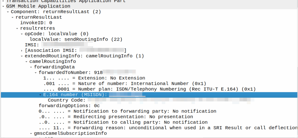
I’ve covered how SS7/ISUP handles call forward before, but the HLR can also store call forwarding information.
This is returned to the MSC when the SendRoutingInfo dialog is performed against the HLR.
If it’s present the MSC will redirect the call to that destination, after bouncing it through CAMEL (if enabled).
A lot simpler than Call Forward in IMS, but same outcome.
A lot of HSSes we see are just HLRs under the hood and only implement a minimalist MMTel feature set for call forwarding for this reason to have it track across both.
SMSc can send an SRI-for-SM, and if the subscriber is absent, the response can include the informServiceCenter message, which lets the SMSc know if it will get sent an alertServiceCentre message when the subscriber comes back online (sends an UpdateLocation).
This means that the SMSc can be notified when it can deliver the message to the subscriber.
It’s got a bunch of flags, which equate to:
sc-AddressNotIncluded means the service center address from the SRI-for-SM was not included in the Message Waiting Data file (and therefore will not get notified via AlertSC when the subscriber comes back online).
If it’s sc-AddressNotIncluded is set to False it means that the service center address has been added to the Message Waiting Data file, so will get an alertServiceCenter message when the sub comes back online (Double negative).
mnrf-Set means Mobile subscriber Not Reachable (Not registered on any MSC)
mcef-Set means Memory Capacity Exceeded Flag is set as the HLR has run out of memory in the Message Waiting Data file and cannot store any more data (So you won’t get notified via AlertSC when the subscriber comes back online)
mnrg-Set is for Mobile subscriber Not Reachable for GPRS (When using SGSN delivery is not registered for packet service).
mnr5g-Set means the SC will get notified when the subscriber becomes reachable from 5G serving nodes.
mnr5gn3g is a mystery – The only references to it I can find are in the ASN1 spec (hence why Wireshark decodes it) but as to its purpose, I can only guess.
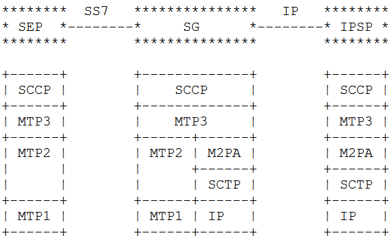
This is part of a series of posts looking into SS7 and Sigtran networks. We cover some basic theory and then get into the weeds with GNS3 based labs where we will build real SS7/Sigtran based networks and use them to carry traffic.
In our last post we talked about moving MTP2 onto IP and the options available.
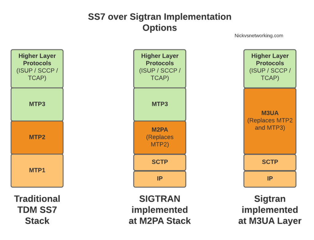
When we split the SS7 stack onto IP we don’t need to do this at the Data Link Layer, we can instead do it higher up the stack. This is where we introduce M3UA.
MTP Level 3 User Adaptation Layer – M3UA replaces MTP3 with an IP based equivilent.
This is different to how we’d handle it with M2UA or M2PA where MTP3 remained unchanged, when you deploy M3UA links, there is no MTP3 anymore – it’s replaced with an IP based protocol transported via SCTP designed to do the same role as MTP3 but over IP – That protocol is M3UA.
This means the roles handled in MTP3 such as managing which available point codes are reachable over which linksets, failover, load sharing and reporting are all now handled by the M3UA protocol, because we loose the ability to just rely on MTP3 to do those things like we did when using lower layer protocols like M2PA or MTP2.
So what do you need to know to use M3UA?
Well, the first concept we need to wrap our head around is that we no longer have linksets or pointcode routes (We do, but they’re different) but instead have Application Servers, Application Server Processes and Routing Contexts.
If you’re following along at home and you want to hook your M3UA compatible AS into the Cisco ITP STP, I’ll be including the commands as we go along. The first step on the Cisco (assuming you’ve already defined the basic SS7 config) is to create a local M3UA instance:
cs7 m3ua 2905
 local-ip 10.179.2.154
With that out of the way, let’s cover ASPs & ASs (hehe – Ass).
You can think of the Application Server Process (ASP) as the client end of the “link set” of our virtual SS7 stack, it handles getting the SCTP association up, what IPs, ports and SCTP parameters are needed, and listens and communicates based on that, here’s an example on the Cisco ITP:
cs7 asp NickLab_ASP 2905 2905 m3ua
 remote-ip 10.0.1.252
 remote-ip 172.30.1.12
The ASP connects to a Signaling Gateway (In practical terms this is an STP).
That’s simple enough and now we can do our SCTP handshake, but nothing is going to get routed without introducing the Application Server (AS) itself, which is where we configure the routing and link to 1 or more ASPs and how we want to share traffic among them.
Point codes are still used in M3UA for sending traffic from an M3UA AS but it’s not what controls the routing to an AS.
That probably sounds confusing, I send traffic based on point code, but the traffic does’t get to the M3UA AS via point code? What gives?
Well, first we’ve got to introduce the Routing Context in M3UA.
Routing Contexts define what destinations are served by this AS. As an example, on our STP we’ll define a Routing Context inside the ITP inside the AS section, in this example we’re creating Routing Key 1 which will handle traffic to the point code 5.123.2, but we could equally define a routing-key for a given Global Title address too.
cs7 instance 0 as NickPC m3ua
 routing-key 1 5.123.2
 asp NickLab_ASP
 traffic-mode broadcast
Notice we didn’t define Routing Key X -> Point Code Y -> ASP Z ? That’s because we may have one or more ASPs associated with this (remember ASPs are kinda like Linksets).
For example the Point Code for an HLR might have multiple ASPs behind it, with traffic-mode loadshare to load balance the requests among all the HLRs.
So what does it look like to bring this up? Let’s take a look at a link coming up.
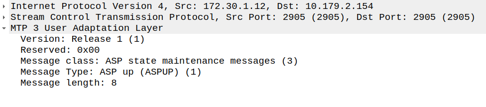
Now our ASP has told the Signaling Gateway it’s there, so our Signaling Gateway returns an ASPUP_ACK to confirm it’s got the message and the current AS state is inactive.
ASP Up Ack Message from SG (STP) to ASP
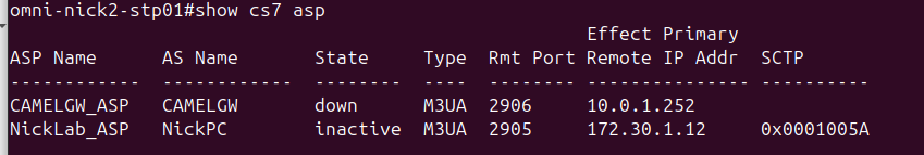
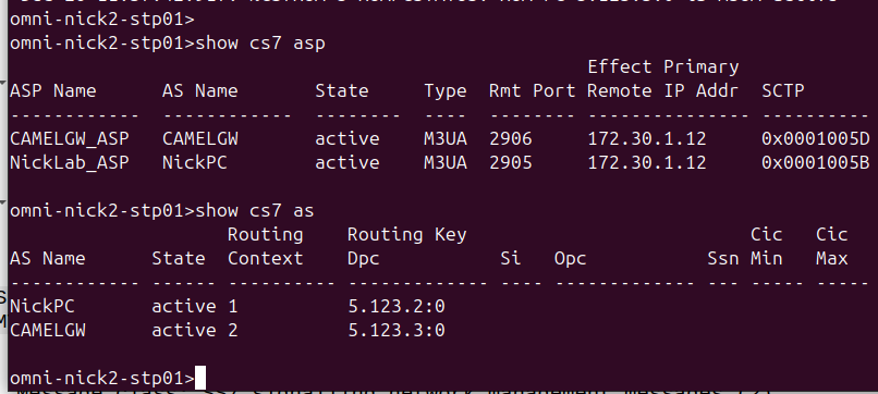
And with that our ASP is in “an up state, “inactive” state; it’s connected to the STP, but without any ASes associated with our ASP, it’s akin to having link layer but nothing else.
State in the STP showing an ASP without an active AS
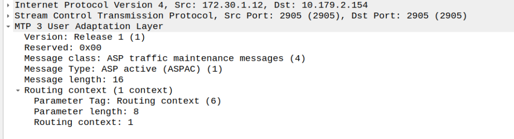
So next our ASP will send an ASPAC (ASP Active) message for the given routing contexts the AS serves, in this case, Routing Context 1.
ASP Active Message from ASP to SG (STP)
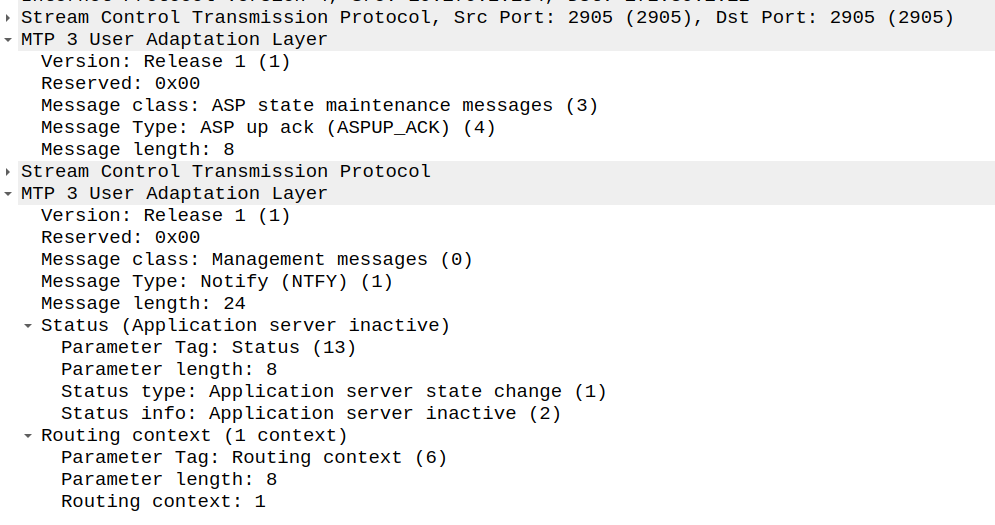
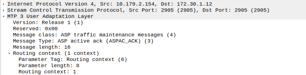
And with that, the Signaling Gateway (STP) send back an an ASPAC_ACK (ASP Active Ack) to confirm it’s got it, and the state changes.
ASP Active Ack Message from SG (STP) to ASP
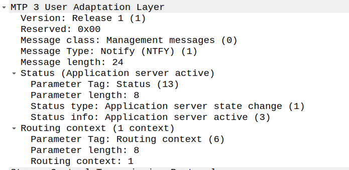
Because of how MTP3 worked advertising available point codes, the SG (STP) needs to tell the AS/ASP how it sees the world and the state of the connection.
This is done with a NTFY (Notify) message from the STP/SG to indicate the state has changed to active, and what destinations are reachable, and at this point, we’re good to start handling traffic for that Routing Context.
And with that, we can start handling M3UA traffic.
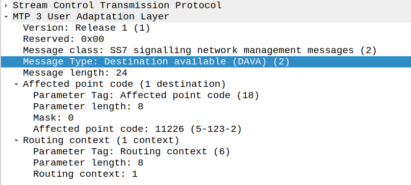
There’s only one more key dialog to wrap your heads around that’s the DAVA and DUNA messages.
DAVA is Destination Available, and DUNA is Destination Unavailable. The SG (STP) will send these messages to ASP/AS every time the reachability of a neighboring point code changes.
That’s the basics covered, I’m in the process of developing an HLR (Running with MAP/TCAP/SCCP/M3UA) extension for PyHSS, which in the future will allow us to experiment with more M3UA endpoints.
Had an interesting fault come across my desk the other day; calls were failing when the called party (an SSP we talk to via SS7/ISUP) had an exchange based call forward in place.
We’re a SIP based network, but we do talk some SS7/ISUP on the edges, and it was important that we handled this correctly.
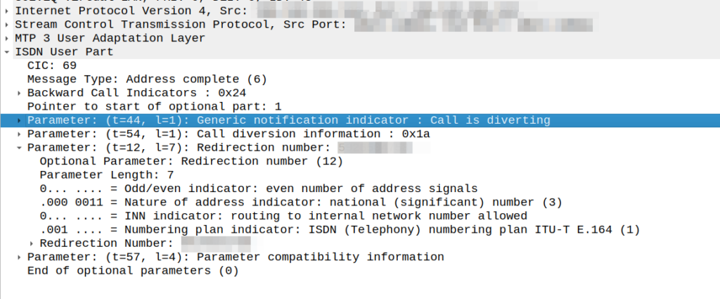
I could see in the Address Complete Message (ACM) sent back to our network that there was redirection information here:
We would see the B party SSP release the call as soon as it sent this.
This made me wonder if we, as the originating network, were supposed to redirect to the new B party and send a new Initial Address Message?
After a lot of digging in the ITU Q.7xx docs (I’m not where near as fast at finding information in specs written prior to my birth, than I am with the 3GPP specs) I found my answer – These headers are informational only, the B party SSP is meant to re-target the message, and send us an Alerting or Answer message when it’s done so.
CAMEL is primarily focused on charging for Voice & SMS services, as data generally uses Diameter, so it’s voice and SMS we’ll focus on.
CAMEL is spoken between the MSC (gsmSSF) and the OCS (gsmSCF).
Basic Call State Model
CAMEL is closely related to the Intelligent Network stuff on the 1980s, and steals a lot of it’s ideas from there, unfortunately if you’re to read the CAMEL standard it also implies you were involved in IN stuff and had been born at that point, alas I was neither.
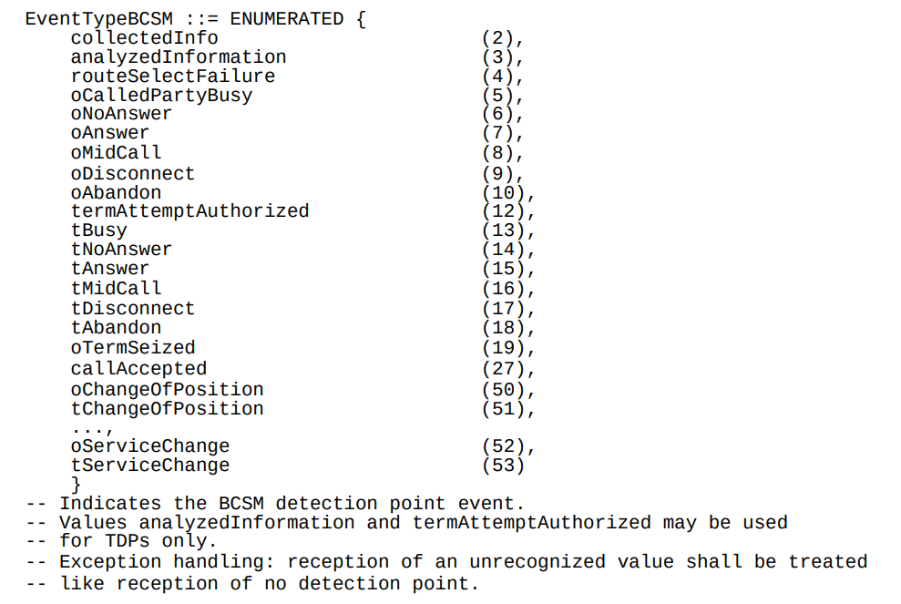
So the key to understanding CAMEL is the Basic Call State Model (BCSM) which is a model of all the different states a call can be in, such as ringing, answered, abandoned, call failed, etc, etc.
Over CAMEL, our OCS can be told by the MSC when a certain event happens; the MSC can tell the OCS, that the call has changed state. For example a BCSM event might indicate the call has hung up, is ringing, cancelled, etc.
Below is the list of all the valid BCSM states:
List of BCSM states for events
Basic MO Call with CAMEL
Our subscriber makes an outbound call.
Based on the data the MSC has in it from the HLR, it knows that we should use CAMEL for this call, and it has the SCCP Address of the OCS (gsmSCF) it needs to send the CAMEL messages to.
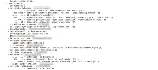
So the MSC sends an InitialDP message to the OCS (via it’s Global Title Address) to Authorize the call that the user is trying to make.
This is like any other Authorization step for an OCS, which allows the OCS to authorize the call by checking the subscriber is valid, check if they’re allowed to call that destination and they’ve got the balance to do so, etc.
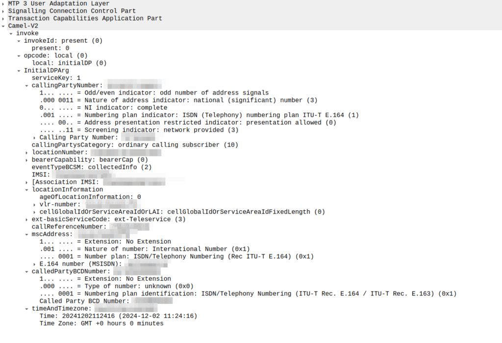
initialDP message from an MSC to an OCS
The initialDP (Initial Detection Point) is telling our OCS all about the call event that’s being requested, who’s calling, what number they’ve dialed, where they are in the network (of note especially if they’re roaming), etc, etc.
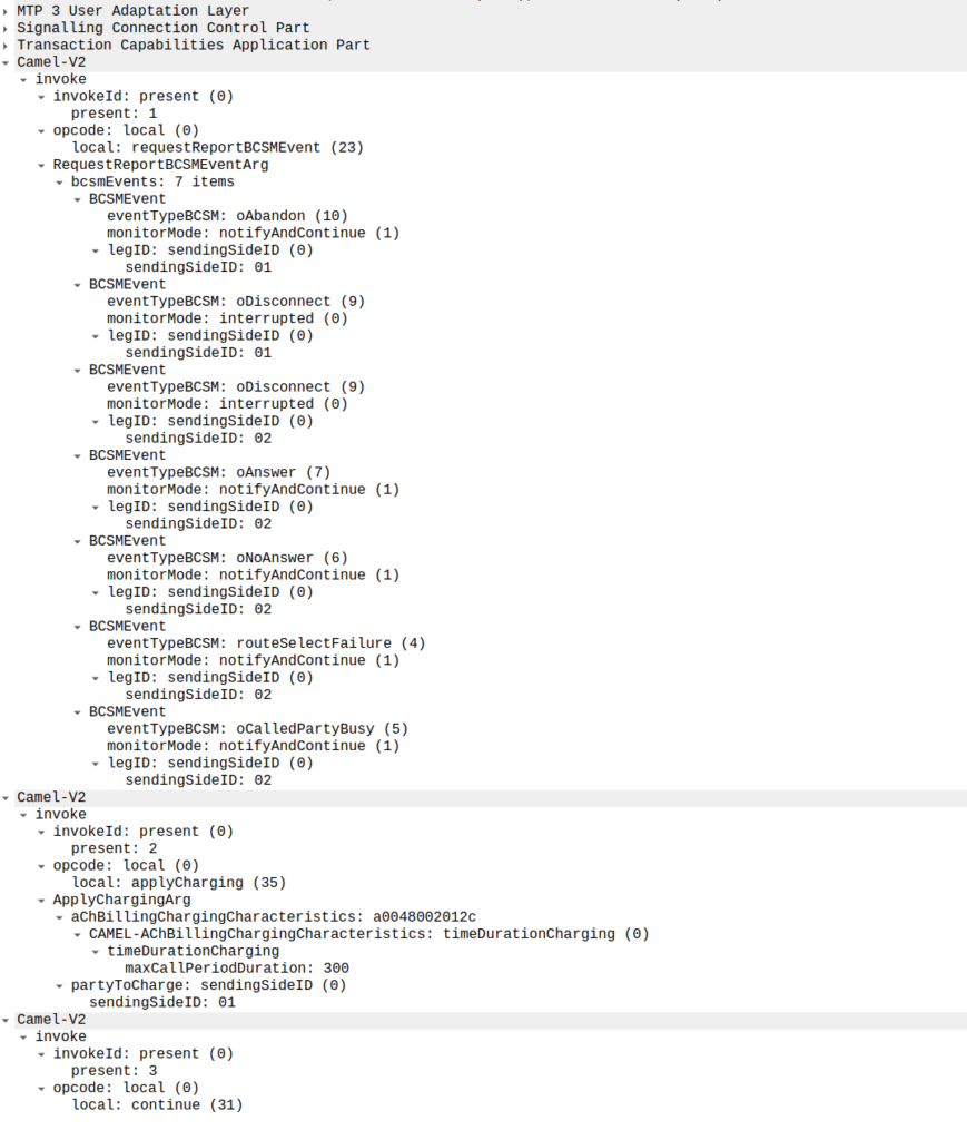
Generally the OCS also uses this message as a chance to subscribe to BCSM Events using RequestReportBCSMEventArg so the OCS will get notified by the MSC when the state of the call changes. This means the MSC will tell us when the state of the call changes; events like the call getting answered, disconnected, etc. This is critical so we know when the call gets answered and hung-up, so we can charge correctly.
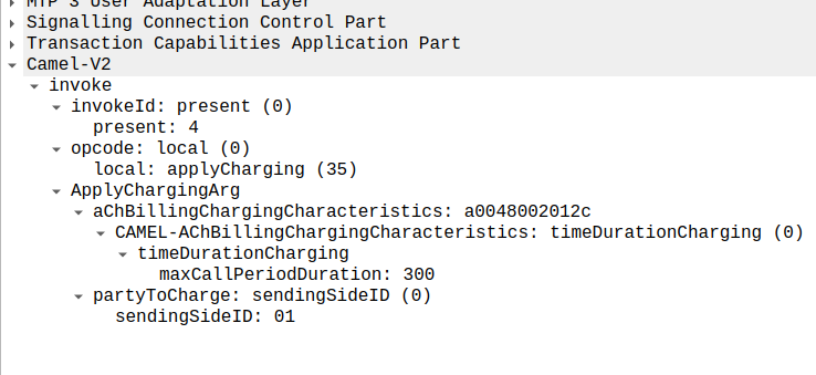
In the below example, as well as sending the Continue and RequestReportBCSMEventArg the OCS is also setting the ChargingArgs for this call, so the MSC knows who to charge (the caller) set via sendingSide and that the MSC must send an Apply Charging Report (ACR) messages every 300 units (1 unit = 100 ms, so a value of 300 = 300 x 100 milliseconds = 30 seconds) so the OCS keeps track of what’s going on.
continue sent by the OCS to the MSC, also including reportBCSMEvent and applyCharging messages
Or in a slightly less appropriate analogy but easier to understand for SIP folks, the InitialDP is sent for INVITE and the 180 RINGING is sent once the continue message is received.
Call is Answered
So at this stage our call can start to ring.
As we’ve subscribed to BCSM events in our last message, the MSC is going to tell us when the call gets answered or the call times out, is abandoned or the sun burns out.
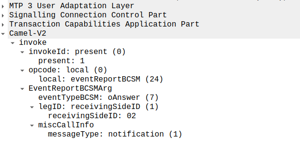
The MSC provides this info a eventReportBCSM, which is very simple and just tells us the event that’s been triggered, in the example below, the call was answered.
eventReportBCSM from MSC to OCS
These eventReportBCSM are informational from the MSC to the OCS, so the OCS doesn’t need to send anything back, but the OCS does need to mark the call as answered so it can start timing the call.
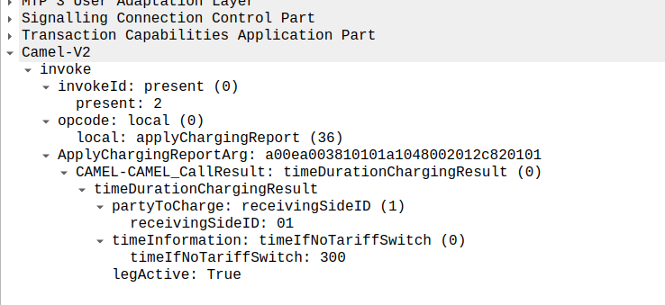
At this stage, the call is connected and our two parties are talking, but our MSC has been told it needs to send us applyChargingReports every 30 seconds (due to the value of 300 in maxCallPeriodDuration) after the call was connected, so the MSC sends the OCS it’s first applyChargingReport 30 seconds after the call was answered:
applyChargingReport sent by the MSC to the OCS every reporting period
We can calculate the duration of the call so far based on the time of the eventReportBCSM, then the OCS must make a decision of if it should allow the call to continue or not.
For simplicity’s sake, let’s imagine we’re still got a balance in the OCS and the OCS wants the call to continue, the OCS send back an applyCharging message to the MSC in response, and includes the current allowed maxCallPeriodDuration, keeping in mind the value is x100 and in nanoseconds (so this is 30 seconds).
applyCharging from the OCS back to the MSC
Perfect, our call is good to go for another 30 more seconds, son in 30 seconds we’ll get another ACR messages from MSC to the OCS to keep it abreast of what’s going on.
Now one of two things is going to happen, either subscriber is going to burn through all of their minutes, and get their call cutoff, or the call will end while they’ve still got balance, let’s look at both scenarios.
Normal Hangup Scenario
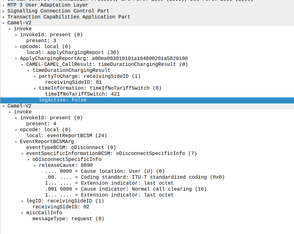
When the call ends, we get an applyChargingReport from the MSC to the OCS.
As we’ve subscribed to reportBCSMEvent we get both the applyChargingReport with legActive: False` so we know the call has hungup, and we’ve got an event report to tell us more about the event, in this case a hangup from the Originating Side.
reportBCSMEvent and applyChargingReport Sent by the MSC to the OCS to indicate the call has ended, note the legActive flag is now false
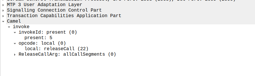
Lastly the OCS confirms by sending a releaseCall to the MSC, to indicate all legs should now terminate.
releaseCall Sent by OCS to MSC at the very end
So that’s it!
Obviously there are other flows, such as running out of balance mid-call, rejecting a call, SMS and PBX / VPN services that rely on CAMEL, but hopefully you now understand the basics of how CAMEL based charging looks and works.
If you’re looking for a CAMEL capable OCS or a CAMEL to Diameter or API gateway, get in touch!
This is the next post in my series on SS7, and today we’re taking a look at SCCP the Signalling Connection Control Part (SCCP).
High Level
Global Title uses the routing features from SCCP, which is another layer on top of MTP3.
SCCP allows us to route on more than just point code, instead we can route based on two new fields, Subsystem Number and Global Title.
Subsystem Number is the type of system we are looking to reach, ie an HLR, MSC, CAMEL Gateway, etc.
The Global Title generally looks like an E.164 formatted phone number, and often it is just that.
Somewhere along the chain (typically at the end of it) an STP somewhere needs to perform Global Title Translation to analyse the SCCP header (Subsystem Number, Point Code & Global Title) and finally turn that into a single point code to route the MTP3 message to.
The advantage of this is we are no longer just limited to routing messages based on Point Code.
This is how the international SS7 Network used for roaming is structured and addressed – All using Global Title rather than Point Codes.
The need for SCCP
For starters, after all this talk of MTP3 and Point Codes, why the need to add SCCP?
Let’s go back in time and look at the motivators…
1. Address space is finite
Point codes are great, and when we’ve spoken about them before, I’ve compared them to IPv4 address, but rather than ranging from 0.0.0.0 to 255.255.255.255 (32 bits on IPv4) international signaling point codes range from 0.0.0 to 7.255.7 (14 bits).
The problem with IPv4’s 32 bit addresses is they run out. The problem with the ITU International Signaling Point Codes is that they too, are a limited resource with only 16,383 possible ISPCs.
~700 operators worldwide each with ~100 network elements would be 70k point codes to address them all – That’s not going to fit into our 16k possible Point Codes.
Global Title fixes this, because we’re able to use E.164 phone number ranges (which are plentiful) for addressing, we’re still not at IPv6 levels of address space, but pretty hefty.
2. Service Discovery by Subsystem
Now imagine you’re a VLR looking to find an HLR. The VLR and the HLR are both connected to an STP, but how does the VLR know where to reach the HLR?
One option would be to statically set every route for the Point Code of every HLR into every possible VLR and visa-versa, but that gets messy fast.
What if the VLR could just send a request to the STP and indicate that the request needs to be routed to any HLR, and the STP takes care of finding a SS7 node capable of handling the request, much a Diameter Routing Agent routes based on Application ID.
SCCP’s “Subsystem Number” routing can handle this as we can route based on SSN.
3. Service Discovery by MSISDN
Having an SMS destined to a given MSISDN requires the SMSc to know where to route it.
Likewise an MSC wanting to call a given number.
There’s a lot of MSISDN ranges. Like a lot. Like every phone mobile number.
Having every a table on every SSP/SCP in the network know where every MSISDN range is in the world and what point code to go through to reach it is not practical.
Instead, being able to have the SCP/SSPs (like our MSC or SMSc) send all off-net traffic to an STP frees us the individual SCP/SSPs from this role; they just forward it to their connected STP.
Our STP can analyse the destination MSISDN and make these routing decisions for us, using Global Title Translation based on rules in the Global Title Table on the STP.
For example by adding each of the domestic / national MSISDN ranges/prefixes into the Global Title Table on the STP (along with the corresponding point code to route each one to), the STP can look at the destination MSISDN in the message and forward to the STP for the correct operator.
Likewise a route can match anything where the Global Title address is outside of the local country and send it to an international signaling provider.
Global title takes care of this as we can route based on a phone number.
4. Tokenistic Security
By “Hiding” network elements behind Global Titles, you don’t expose as much information about your internal network, and the only way people can “find” your network elements would be scanning through all the possible addresses in your (publicly advertised) Global Title range (wardialing is back baby!).
But the phrases “Security” and “SS7” don’t really belong together…
The SCCP Header
The SCCP header has a Called Party and a Calling Party, and this is where the magic happens.
These can be made up for any number of 3 parts:
Global Title Address
Subsystem Number
Point Code
We can route on any combination of these.
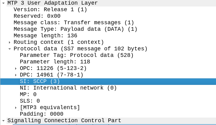
To indicate we’re using SCCP, we set the Signaling Indicator bit in the M3UA / MTP3 message to SCCP:
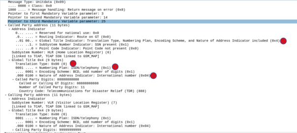
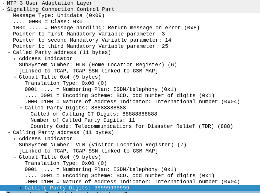
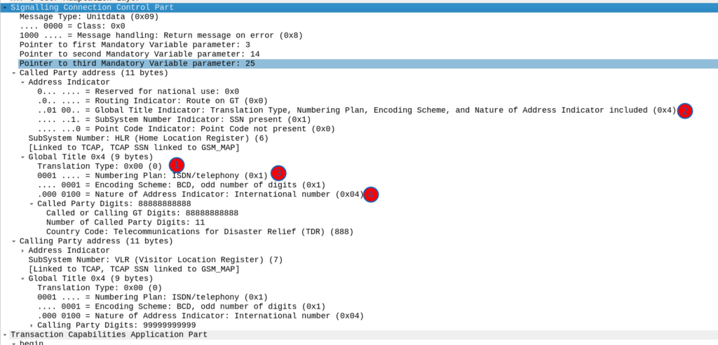
Great, now we can look at our SCCP header.
It looks like there’s a lot going on, but we can see the calling and called party (888888888 is called by 9999999999) with the Subsystem number set (888888888 is called for subsystem HLR, from 999999999 which is a VLR).
The closest TCP/IP analogy I can think of here is that of port numbers, there’s still an IP (Point code) but the port number allows us to specify multiple applications that run at a higher layer. This analogy falls down when we consider that the Point Code is generally set to that of your STP, not the final STP.
For this to work, we’ve got to have at least one Signaling Transfer Point in the flow, where we send the request to.
Somewhere (generally at the end of the chain of STPs), an STP is going to perform Global Title Translation.
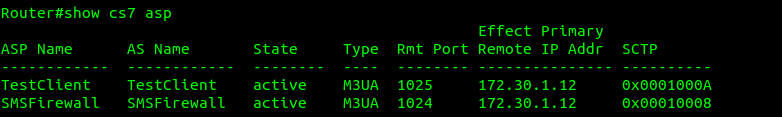
What does this look like? Well let’s have a look at my GT table for the example above, in my lab network, I’ve got two nodes attached (via M3UA but could equally be on MTP3 links), my test MAP client where I’m originating this traffic, and an SMS Firewall, I can see they’re both up here:
Now knowing this I need to setup my SCCP routing for Global Title. In the screenshot above, the Called Party was 888888888 with Subsystem Number 7. Inside the SCCP request, there’s a few other fields, the Translation Type we have set to 0, Global Title Indicator is 4 (route on Global Title), while Numbering Plan Indicator is 1 (ISDN) and Nature of Address Indicator is 4 (International).
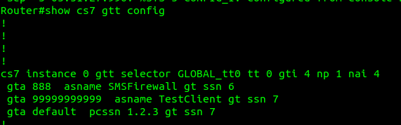
So on my Cisco ITP I define a GTT Selector to target traffic with these values, Translation Type is 0, Global Title Indicator is 4, Number Plan is 1 and the Nature of Address Indicator is 4.
So we’d define a Global Title Translation selector like the one below to match this traffic:
But that’s only matching the group of traffic, it’s not going to match based on the actual SCCP Called Party. So now I need to define a translation for each Global Title address (Called /Calling party) or prefix I want to route, I’ve setup anything starting with 888 to route to the `SMSFirewall` ASP endpoint.
I could stop here and my request addressed to 888888888 would make it to the SMSFirewall ASP, but the response never would, like in all SS7 routing, we need to define the return route translation too, which is what I’ve done for 999999 to route to the TestClient.
Lastly I’ve added a wildcard route, this means if this STP doesn’t know how to resolve a GT address matching the rules in the top line, it’ll forward the request to the STP at point code 1.2.3 – This is how you’d do your connection to an IPX / Signaling exchange.
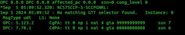
Debugging this can be a massive pain in the backside, but if you enable logging you can see when GT rules are not matched, like in the example below.
If your network is quiet enough, it’s sometimes easier to just make your rules based on what you observe failing to route.
So with those routes in place, when we send a request with the Global Title called party starting with 8888888 it’s routed to M3UA ASP SMSFirewall, which handles the request, and then sends the response back to the MAPClient M3UA ASP.
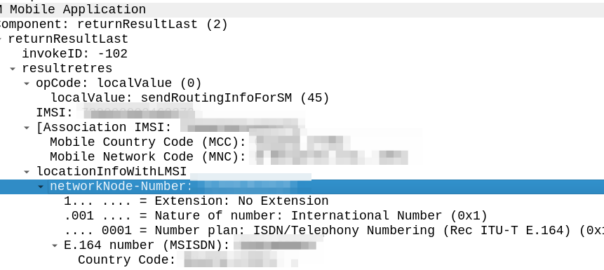
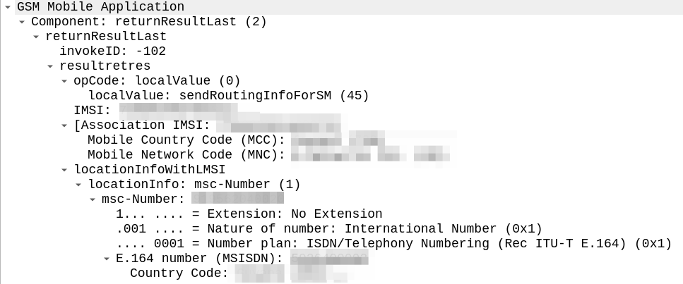
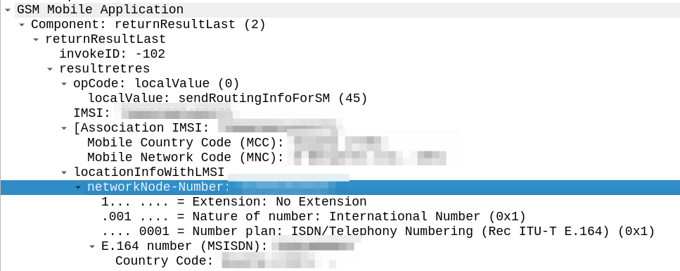
The other day I was facing an issue with our SMSc inter-working with another operator via MAP.
Our SRI-for-SM responses were relayed back to their nodes, but it was like it couldn’t parse the message.
I got some “known good” traffic to compare this against to work out what we’re doing wrong.
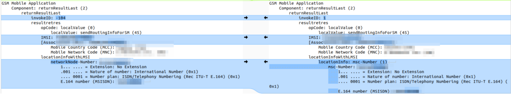
The difference in the two examples below is subtle, but it’s there – On the example on the left (failing) we are including an msc-number in the locationInfoWithLMSI field, while on the right we’ve got a “Network Node Number”.
“Okay” I thought to myself, we’re just doing something wrong with the encoding of the MAP body, so I did my usual diff trick from Wireshark:
Oddly in the raw form both these values decode the same, if I feed the values on the left into our decoder, and then encode, I get the values on the right, with the exact same hex body – and this is all ASN.1; so there’s very little room for error anyway.
So what gives? Why does Wireshark show one MAP body differently to the other, with the same hex bytes?
Well, the issue is not within my GSM MAP body and the content I include there, but rather in the TCAP layer above it, specifically the `application-context-name`.
We’re indicating support for GSM MAP v3 (0.4.0.0.1.0.20.3), while the other operator is using MAPv2 ( 0.4.0.0.1.0.20.2 ) even though their IR.21 indicates it should be GSM MAP v3.
Now our SRI-for-SM responses are based on the GSM MAP version received, rather than reported as supported, and we don’t have to deal with this for handling requests anymore.
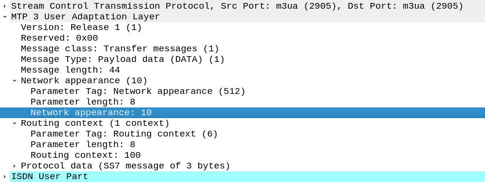
Short one, The other day I needed to add a Network Appearance on an SS7/SS7 M3UA linkset.
Network Appearances on M3UA links are kinda like a port number, in that they allow you to distinguish traffic to the same point code, but handled by different logical entities.
When I added the NA parameter on the Linkset nothing happened.
If you’re facing the same you’ll need to set:
cs7 multi-instance
In the global config (this is the part I missed).
Then select the M3UA linkset you want to change and add the network-appearance parameter:
network-appearance 10
And bingo, you’ll start seeing it in your M3UA traffic:
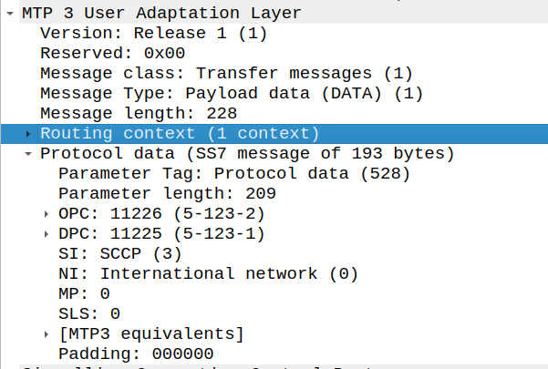
So far in our lab we’ve got connectivity between to points, but we’re not carrying any useful data on top of it.
In the same way that TCP is great, but what makes it really useful is carrying application layers like HTTP on top, MTP3 exists to facilitate carrying higher-layer protocols, like ISUP, MAP, SCCP, etc, so let’s get some traffic onto our network.
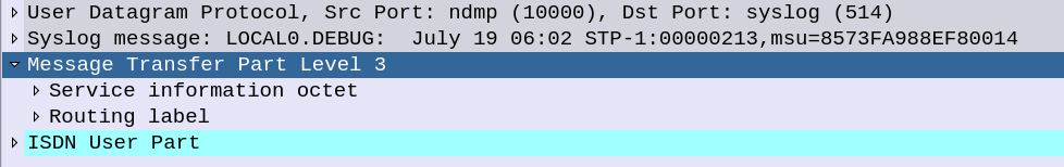
ISUP is the ISDN User Part, ISUP is used to setup and teardown calls between two exchanges / SSPs – it’s the oldest and the most simple SS7 application to show off, so that’s what we’ll be working with today.
If you’ve not dealt much with ISDN in the past, then that’s OK – we’re not going to deep dive into all the nitty gritty of how ISDN Signaling works, but we’ll just skim the surface to showing how SS7/Sigtran transports the ISUPpackets. So you can see how SS7 is used to transport this protocol.
You can think of it a lot like SIP, which is if not the child of ISUP, then it at least bares a striking resemblance.
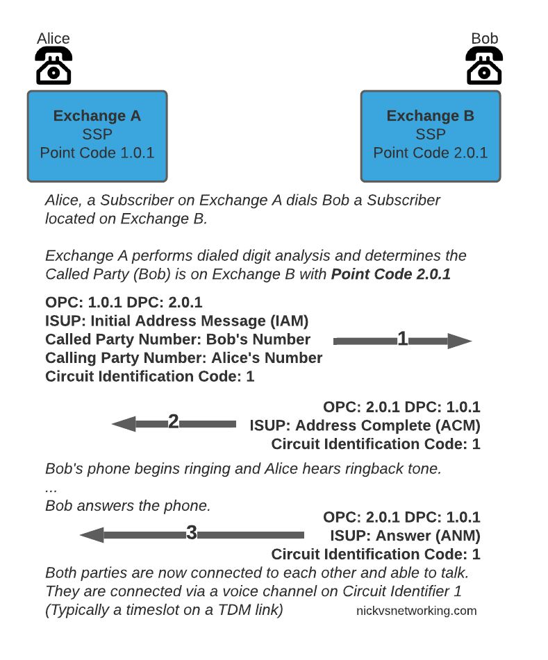
So let’s look at an ISUP call flow:
The call is initiated with an Initial Address Message (IAM), akin to a SIP INVITE, sent by the SSP/Exchange of the calling party to the SSP/Exchange of the called party. When the remote party starts to ring, the remote exchange sends an Address Complete (ACM), which is similar to a 100 TRYING in SIP. Once the remote party answers, the remote exchange sends back an Answer Message (ANM), and our call starts, just like a 200 OK.
Rather than SDP for transferring media, timeslots or predefined channels / circuits are defined, each identified by a number, which both sides will use for the media path.
Finally whichever side terminates the call will send a Release (REL) message, which is confirmed with the Release Complete (RLC).
I told you we’d be quick!
So that’s the basics of ISUP, in our next post we’ll do some PCAP analysis on real world ISUP flows!
This is part of a series of posts looking into SS7 and Sigtran networks. We cover some basic theory and then get into the weeds with GNS3 based labs where we will build real SS7/Sigtran based networks and use them to carry traffic.
So, all going well at this point in the tutorial you’ve got your lab setup with SS7 links between our simulated countries, but we haven’t dug too deep into what’s going on.
Most of the juicy stuff happens in the higher layers, but in this post we’ll look at the Data-Link layer for SS7.
In TDM based SS7 networks, Data Link layer is handled by a layer called “MTP2” – Message Transfer Part 2, which is responsible for flow control and ensuring guaranteed delivery between two points on the network.
MTP2 provides the services you’d typically expect at the Data Link Layer; link alignment, CRC generation/verification, end to end transmission between two points, flow control and sequence verification, etc.
MTP2 is responsible for making the connection between two points capable of carrying those far more interesting upper layers, but it’s really important, particularly when we talk about SIGTRAN/SS7 over IP, to understand how this can be done, so you can understand how the networks fit together.
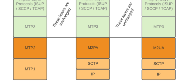
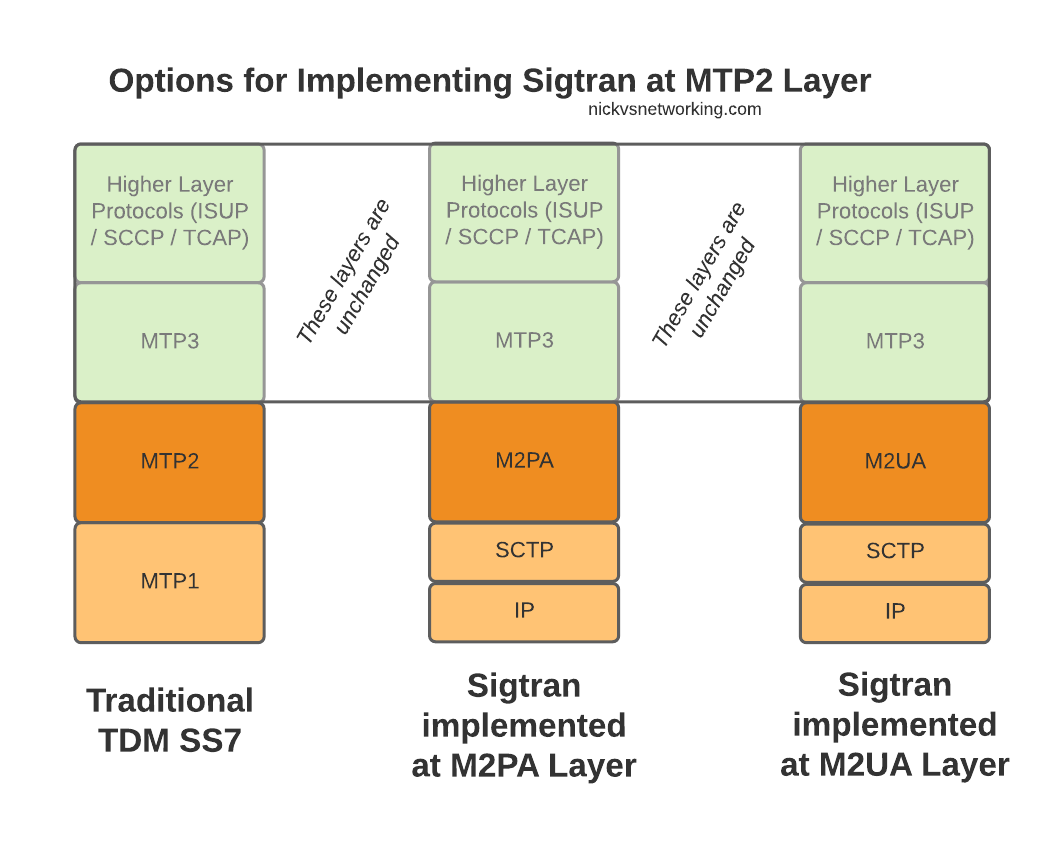
When we move from TDM based SS7 networks to IP based (Sigtran), MTP2 is removed, and can be replaced with one of two options for transporting Layer 2 messaging over IP, M2UA or M2PA.
All the layers above MTP2 on SS7 or M2UA/M2PA on Sigtran, are unchanged, and the upper layers have no visability that underneath, MTP2 has been replaced with M2UA or M2PA.
Taking MTP2 and putting it onto an IP based Layer 2 protocol is only one option for implementing Sigtran, there are others that we’ll look into as we go along, but with this variant the upper layers above Layer 2 (MTP3) remain changed.
Putting SS7 Data Link Layer (MTP2) onto IP
So the two options – M2UA and M2PA. Why do we have two options?
SS7 networks can be really complicated, and different operators may have different needs when converting these networks to IP.
To satisfy those requirements, there’s a bunch of different flavors of SS7 over IP (Sigtran) available to implement, so operators can select the one that meets their needs and use cases.
This means when we’re learning it, there’s a stack of different options to cover.
On the Layer 2 Level, let’s look at the two options we have in some more detail.
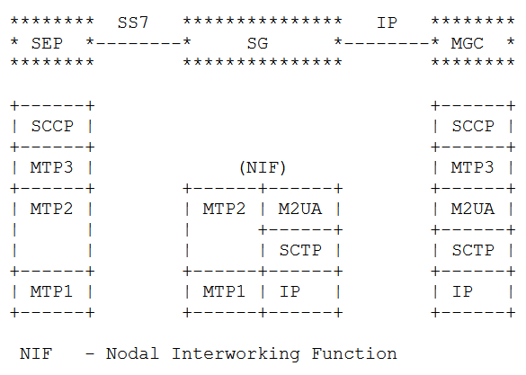
The M2UA Flavour
Image from RFC 4165 / 1.9. Differences Between M2PA and M2UA – Showing M2UA
With a “Nodal Interworking Function” using M2UA, the point codes between our two SS7 nodes remain unchanged.
The SS7 node on the left still talks MTP3 directly with the SS7 node on the right, and the NIF just transparently translates MTP2 into M2UA.
The best analogy I can come up with is that you can think of this as kind of like a Media Converter you’d use for converting between Cat5 to fibre – The devices at each end don’t know they’re not talking over a straight ethernet cable between them, but the media converter changes the transmission medium in between the two in a transparent manner.
M2UA acts in much the same way, except we’re transparently converting the layer 1 & layer 2 signaling, in a way that end devices in the network don’t need to be aware of.
The advantage of this option is that no config changes are needed, we’ve taken our Linksets that were running on TDM and converted them to IP so both ends of the linkset can be moved anywhere with IP connectivity, but transparently to the end devices.
For some carriers this is a real advantage – If you’ve got a dusty SSP running parts of your Customer Access Network, but the engineers who set it up retired long ago and you just want to drop those leased lines, M2UA could be a good option for you.
The disadvantage, as you might have guessed, is that we don’t get much value from just replacing the link from one point to another. It solves one problem, but doesn’t take that much of a step towards converging our network to run over IP.
The M2PA Way
The M2PA way looks a bit different. You’ll notice we’ve got MTP3 on the Signaling Gateway we’re introducing into the network.
This means we need to add a point code between the SS7 node on the left and the SS7 node on the right, where there wasn’t one before, and we will need to update the routing tables on both to know to now route to each other via the point code of our Signaling Gateway rather than directly as the would have before we introduced the Signaling Gateway.
Image from RFC 4165 / 1.9. Differences Between M2PA and M2UA – Showing M2PA
We add another point code and an “active” SS7 device, but now we’ve got a lot more flexibility with what we can do, this no longer needs to be a point-to-point link, but with the introduction of the Signaling Gateway can be point-to-multipoint.
So which to chose? Well the answer is (as always) it depends.
If you cannot change any config on the end device (as the person who understood how all this stuff works retired long ago), then M2UA is the answer. M2UA is just an extension/branch of the MTP2 layer onto IP, it has no understanding / support for the higher-layers of SS7. M2UA is simpler, it doesn’t require as much understanding, it’s a quick-and-easy “drop-in” replacement for back-hauling SS7 onto IP. As it’s fairly dumb, M2UA can also allow us to split the load on a high traffic device across two or more SS7 nodes behind it, somewhat like a layer 2 load balancer, but this use case is pretty irrelevant these days.
M2PA on the other hand introduces a new Point Code (Operating on Layer 3 / MTP3) in between the two devices. This means we introduce a new point code in the path, so have to reconfigure the end devices, but affords us access to a lot of newer features. We can do all sorts of fancy things like routing of MTP3 messages, on the Signaling Gateway. This allows us to structure our network in new ways, rather than just doing what we were doing before but over IP.
Summary
When it comes to taking SS7 traffic and putting it onto IP at the Layer 2 level, we looked at the two most common options – M2PA and M2UA, and the pros and cons of each.
In our next post we’ll look at doing away with MTP2 layer entirely when we look at M3UA…
I’ve recently been writing a lot about SS7 / Sigtran, and couldn’t fit this in anywhere, but figured it may be of use to someone…
In our 3-8-3 formated ITU International Point code, each of the parts have a unique meaning.
The 3 bits in the first section are called the Zone section. Being only 3 bits long it means we can only encode the numbers 0-7 on them, but ITU have broken the planet up into different “zones”, so the first part of our ITU International Point Code denotes which Zone the Point Code is in (as allocated by ITU).
The next 8 bits in the second section (Area section) are used to define the “Signaling Area Network Code” (SANC), which denotes which country a point code is located in. Values can range from 0-255 and many countries span multiple SANC zones, for example the USA has 58 SANC Zones.
Lastly we have the last 3 bits that make up the ID section, denoting a single unique point code, typically a carrier’s international gateway. It’s unique within a Zone & SANC, so combined with the Zone-SANC-ID makes it a unique address on the SS7 network. Being only 3 bits long means that we’ve only got 8 possible values, hence so many SANCs being used.
2
Europe
3
Greenland, North America, the Caribbean, and Mexico
This is part of a series of posts looking into SS7 and Sigtran networks. We cover some basic theory and then get into the weeds with GNS3 based labs where we will build real SS7/Sigtran based networks and use them to carry traffic.
Having a direct Linkset from every Point Code to every other Point Code in an SS7 network isn’t practical, we need to rely on routing, so in this post we’ll cover routing between Point Codes on our STPs.
Let’s start in the IP world, imagine a router with a routing table that looks something like this:
Simple IP Routing Table
192.168.0.0/24 out 192.168.0.1 (Directly Attached)
172.16.8.0/22 via 192.168.0.3 - Static Route - (Priority 100)
172.16.0.0/16 via 192.168.0.2 - Static Route - (Priority 50)
10.98.22.1/32 via 192.168.0.3 - Static Route - (Priority 50)
We have an implicit route for the network we’re directly attached to (192.168.0.0/24), and then a series of static routes we configure. We’ve also got two routes to the 172.16.8.0/22 subnet, one is more specific with a higher priority (172.16.8.0/22 – Priority 100), while the other is less specific with a lower priority (172.16.0.0/16 – Priority 50). The higher priority route will take precedence.
This should look pretty familiar to you, but now we’re going to take a look at routing in SS7, and for that we’re going to be talking Variable Length Subnet Masking in detail you haven’t needed to think about since doing your CCNA years ago…
Why Masking is Important
A route to a single Point Code is called a “/14”, this is akin to a single IPv4 address being called a “/32”.
We could setup all our routing tables with static routes to each point code (/14), but with about 4,000 international point codes, this might be a challenge.
Instead, by using Masks, we can group together ranges of Point Codes and route those ranges through a particular STP.
This opens up the ability to achieve things like “Route all traffic to Point Codes to this Default Gateway STP”, or to say “Route all traffic to this region through this STP”.
Individually routing to a point code works well for small scale networking, but there’s power, flexibility and simplification that comes from grouping together ranges of point codes.
Information Overload about Point Codes
So far we’ve talked about point codes in the X.YYY.Z format, in our lab we setup point codes like 1.2.3.
This is not the only option however…
Variants of SS7 Point Codes
IPv4 addresses look the same regardless of where you are. From Algeria to Zimbabwe, IPv4 addresses look the same and route the same.
In SS7 networks that’s not the case – There are a lot of variants that define how a point code is structured, how long it is, etc. Common variants are ANSI, ITU-T (International & National variants), ETSI, Japan NTT, TTC & China.
The SS7 variant used must match on both ends of a link; this means an SS7 node speaking ETSI flavoured Point Codes can’t exchange messages with an ANSI flavoured Point Code.
Well, you can kinda translate from one variant to another, but requires some rewriting not unlike how NAT does it.
ITU International Variant
For the start of this series, we’ll be working with the ITU International variant / flavour of Point Code.
ITU International point codes are 14 bits long, and format is described as 3-8-3. The 3-8-3 form of Point code just means the 14 bit long point code is broken up into three sections, the first section is made up of the first 3 bits, the second section is made up of the next 8 bits then the remaining 3 bits in the last section, for a total of 14 bits.
So our 14 bit 3-8-3 Point Code looks like this in binary form:
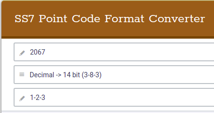
If you’re dealing with multiple vendors or products,you’ll see some SS7 Point Codes represented as decimal (2067), some showing as 1-2-3 codes and sometimes just raw binary. Fun hey?
So why does the binary part matter? Well the answer is for masks.
To loop back to the start of this post, we talked about IP routing using a network address and netmask, to represent a range of IP addresses. We can do the same for SS7 Point Codes, but that requires a teeny bit of working out.
As an example let’s imagine we need to setup a route to all point codes from 3-4-0 through to 3-6-7, without specifying all the individual point codes between them.
Firstly let’s look at our start and end point codes in binary:
100-00000100-000 = 3-004-0 (Start Point Code)
100-00000110-111 = 3-006-7 (End Point Code)
Looking at the above example let’s look at how many bits are common between the two,
100-00000100-000 = 3-004-0 (Start Point Code)
100-00000110-111 = 3-006-7 (End Point Code)
The first 9 bits are common, it’s only the last 5 bits that change, so we can group all these together by saying we have a /9 mask.
When it comes time to add a route, we can add a route to 3-4-0/9 and that tells our STP to match everything from point code 3-4-0 through to point code 3-6-7.
The STP doing the routing it only needs to match on the first 9 bits in the point code, to match this route.
SS7 Routing Tables
Now we have covered Masking for roues, we can start putting some routes into our network.
In order to get a message from one point code to another point code, where there isn’t a direct linkset between the two, we need to rely on routing, which is performed by our STPs.
This is where all that point code mask stuff we just covered comes in.
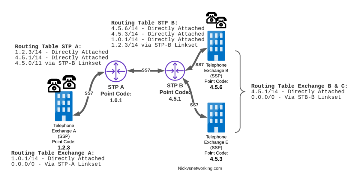
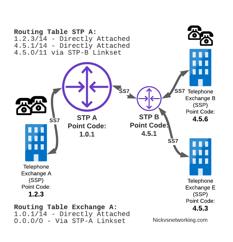
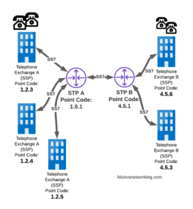
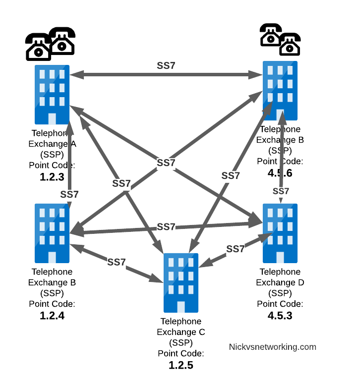
Let’s look at a diagram below,
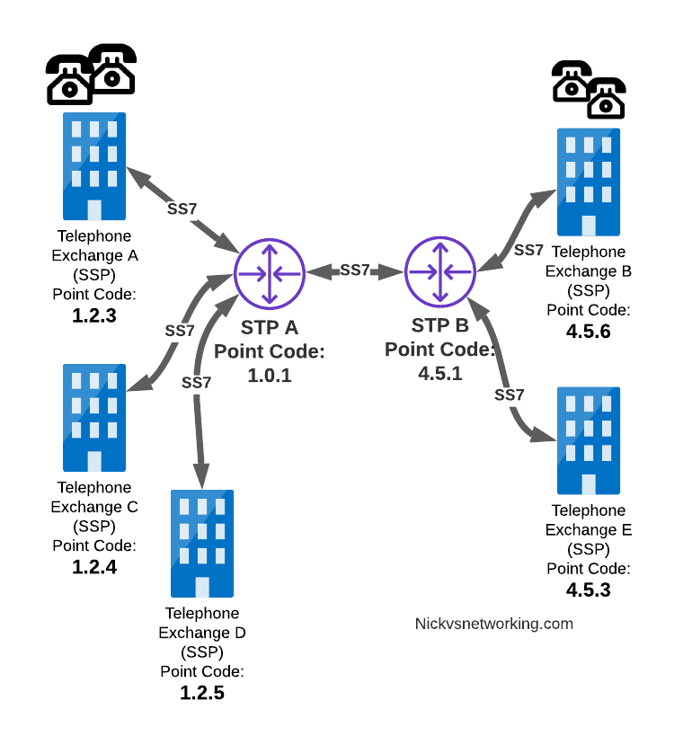
Let’s look at the routing to get a message from Exchange A (SSP) on the bottom left of the picture to Exchange E (SSP) with Point Code 4.5.3 in the bottom right of the picture.
Exchange A (SSP) on the bottom left of the picture has point code 1.2.3 assigned to it and a Linkset to STP-A. It has the implicit route to STP-A as it’s got that linkset, but it’s also got a route configured on it to reach any other point code via the Linkset to STP-A via the 0.0.0/0 route which is the SS7 equivalent of a default route. This means any traffic to any point code will go to STP-A.
From STP-A we have a linkset to STP-B. In order to route to the point codes behind STP-B, STP-A has a route to match any Point Code starting with 4.5.X, which is 4.5.0/11. This means that STP-A will route any Point Code between 4.5.1 and 4.5.7 down the Linkset to STP-B.
STP-B has got a direct connection to Exchange B and Exchange E, so has implicit routes to reach each of them.
So with that routing table, Exchange A should be able to route a message to Exchange E.
But…
Return Routing
Just like in IP routing, we need return routing. while Exchange A (SSP) at 1.2.3 has a route to everywhere in the network, the other parts of the network don’t have a route to get to it. This means a request from 1.2.3 can get anywhere in the network, but it can’t get a response back to 1.2.3.
So to get traffic back to Exchange A (SSP) at 1.2.3, our two Exchanges on the right (Exchange B & C with point codes 4.5.6 and 4.5.3) will need routes added to them. We’ll also need to add routes to STP-B, and once we’ve done that, we should be able to get from Exchange A to any point code in this network.
There is a route missing here, see if you can pick up what it is!
So we’ve added a default route via STP-B on Exchange B & Exchange E, and added a route on STP-B to send anything to 1.2.3/14 via STP-A, and with that we should be able to route from any exchange to any other exchange.
One last point on terminology – when we specify a route we don’t talk in terms of the next hop Point Code, but the Linkset to route it down. For example the default route on Exchange A is 0.0.0/0 via STP-A linkset (The linkset from Exchange A to STP-A), we don’t specify the point code of STP-A, but just the name of the Linkset between them.
Back into the Lab
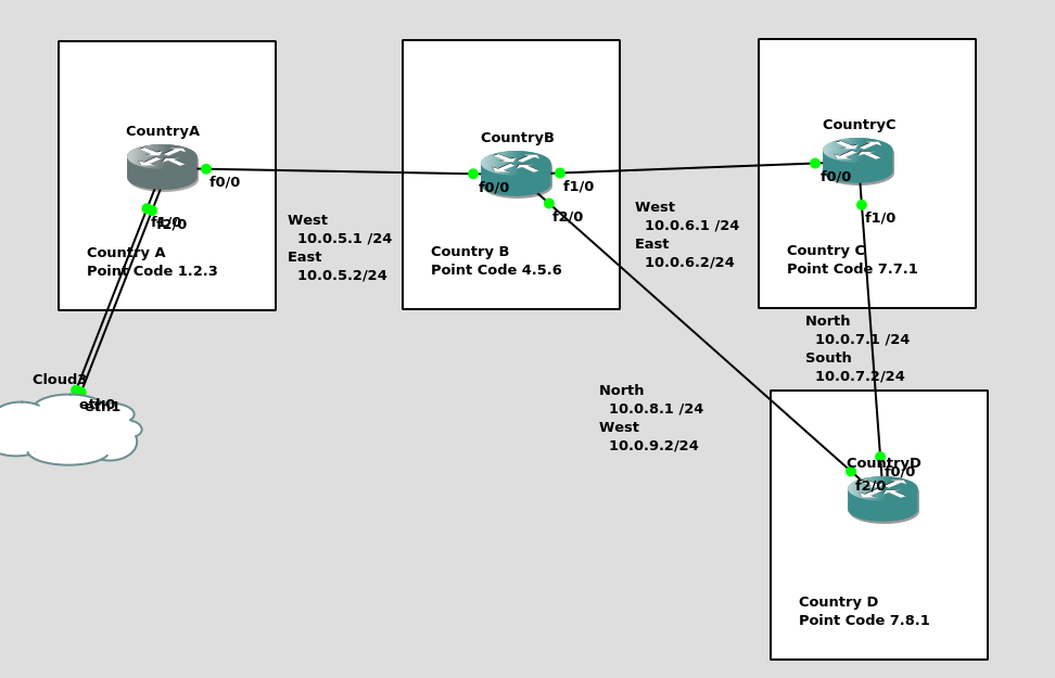
So back to the lab, where we left it was with linksets between each point code, so each Country could talk to it’s neighbor.
Let’s confirm this is the case before we go setting up routes, then together, we’ll get a route from Country A to Country C (and back).
So let’s check the status of the link from Country B to its two neighbors – Country A and Country C. All going well it should look like this, and if it doesn’t, then stop by my last post and check you’ve got everything setup.
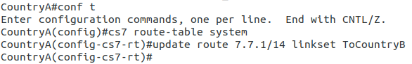
So let’s add some routing so Country A can reach Country C via Country B. On Country A STP we’ll need to add a static route. For this example we’ll add a route to 7.7.1/14 (Just Country C).
That means Country A knows how to get to Country C. But with no return routing, Country C doesn’t know how to get to Country A. So let’s fix that.
We’ll add a static route to Country C to send everything via Country B.
CountryC#conf t
Enter configuration commands, one per line.  End with CNTL/Z.
CountryC(config)#cs7 route-table system
CountryC(config)#update route 0.0.0/0 linkset ToCountryB
*Jan 01 05:37:28.879: %CS7MTP3-5-DESTSTATUS: Destination 0.0.0 is accessible
So now from Country C, let’s see if we can ping Country A (Ok, it’s not a “real” ICMP ping, it’s a link state check message, but the result is essentially the same).
By running:
CountryC# ping cs7 1.2.3
*Jan 01 06:28:53.699: %CS7PING-6-RTT: Test Q.755 1.2.3: MTP Traffic test rtt 48/48/48
*Jan 01 06:28:53.699: %CS7PING-6-STAT: Test Q.755 1.2.3: MTP Traffic test 100% successful packets(1/1)
*Jan 01 06:28:53.699: %CS7PING-6-RATES: Test Q.755 1.2.3: Receive rate(pps:kbps) 1:0 Sent rate(pps:kbps) 1:0
*Jan 01 06:28:53.699: %CS7PING-6-TERM: Test Q.755 1.2.3: MTP Traffic test terminated.
We can confirm now that Country C can reach Country A, we can do the same from Country A to confirm we can reach Country B.
But what about Country D? The route we added on Country A won’t cover Country D, and to get to Country D, again we go through Country B.
This means we could group Country C and Country D into one route entry on Country A that matches anything starting with 7-X-X,
For this we’d add a route on Country A, and then remove the original route;
Of course, you may have already picked up, we’ll need to add a return route to Country D, so that it has a default route pointing all traffic to STP-B. Once we’ve done that from Country A we should be able to reach all the other countries:
CountryA#show cs7 route
Dynamic Routes 0 of 1000

Routing table = system Destinations = 3 Routes = 3

Destination            Prio Linkset Name        Route
---------------------- ---- ------------------- -------
4.5.6/14         acces   1  ToCountryB          avail
7.0.0/3          acces   5  ToCountryB          avail


CountryA#ping cs7 7.8.1
*Jan 01 07:28:19.503: %CS7PING-6-RTT: Test Q.755 7.8.1: MTP Traffic test rtt 84/84/84
*Jan 01 07:28:19.503: %CS7PING-6-STAT: Test Q.755 7.8.1: MTP Traffic test 100% successful packets(1/1)
*Jan 01 07:28:19.503: %CS7PING-6-RATES: Test Q.755 7.8.1: Receive rate(pps:kbps) 1:0  Sent rate(pps:kbps) 1:0
*Jan 01 07:28:19.507: %CS7PING-6-TERM: Test Q.755 7.8.1: MTP Traffic test terminated.
CountryA#ping cs7 7.7.1
*Jan 01 07:28:26.839: %CS7PING-6-RTT: Test Q.755 7.7.1: MTP Traffic test rtt 60/60/60
*Jan 01 07:28:26.839: %CS7PING-6-STAT: Test Q.755 7.7.1: MTP Traffic test 100% successful packets(1/1)
*Jan 01 07:28:26.839: %CS7PING-6-RATES: Test Q.755 7.7.1: Receive rate(pps:kbps) 1:0  Sent rate(pps:kbps) 1:0
*Jan 01 07:28:26.843: %CS7PING-6-TERM: Test Q.755 7.7.1: MTP Traffic test terminated.
So where to from here?
Well, we now have a a functional SS7 network made up of STPs, with routing between them, but if we go back to our SS7 network overview diagram from before, you’ll notice there’s something missing from our lab network…
So far our network is made up only of STPs, that’s like building a network only out of routers!
In our next lab, we’ll start adding some SSPs to actually generate some SS7 traffic on the network, rather than just OAM traffic.
This is part of a series of posts looking into SS7 and Sigtran networks. We cover some basic theory and then get into the weeds with GNS3 based labs where we will build real SS7/Sigtran based networks and use them to carry traffic.
So we’ve made it through the first two parts of this series talking about how it all works, but now dear reader, we build an SS7 Lab!
At one point, and SS7 Signaling Transfer Point would be made up of at least 3 full size racks, and cost $5M USD. We can run a dozen of them inside GNS3!
Cisco’s “IP Transfer Point” (ITP) software adds SS7 STP functionality to some models of Cisco Router, like the 2651XM and C7200 series hardware.
Luckily for us, these hardware platforms can be emulated in GNS3, so that’s how we’ll be setting up our instances of Cisco’s ITP product to use as STPs in our network.
For the rest of this post series, I’ll refer to Cisco’s IP Transfer Point as the “Cisco STP”.
Not open source you say! Osmocom have OsmoSTP, which we’ll introduce in a future post, and elaborate on why later…
From inside GNS3, we’ll create a new template as per the Gif below.
You will need a copy of the software image to load in. If you’ve got software entitlements you should be able to download it, the filename of the image I’m using for the 7200 series is c7200-itpk9-mz.124-15.SW.bin and if you go searching, you should find it.
Now we can start building networks with our Cisco STPs!
What we’re going to achieve
In this lab we’re going to introduce the basics of setting up STPs using Sigtran (SS7 over IP).
If you follow along, by the end of this post you should have two STPs talking Sigtran based SS7 to each other, and be able to see the SS7 packets in Wireshark.
As we touched on in the last post, there’s a lot of different flavours and ways to implement SS7 over IP. For this post, we’re going to use M2PA (MTP2 Peer Adaptation Layer) to carry the MTP2 signaling, while MTP3 and higher will look the same as if it were on a TDM link. In a future post we’ll better detail the options here, the strengths and weaknesses of each method of transporting SS7 over IP, but that’s future us’ problem.
IP Connectivity
As we don’t have any TDM links, we’re going to do everything on IP, this means we have to setup the IP layer, before we can add any SS7/Sigtran stuff on top, so we’re going to need to get basic IP connectivity going between our Cisco STPs.
So for this we’ll need to set an IP Address on an interface, unshut it, link the two STPs. Once we’ve confirmed that we’ve got IP connectivity running between the two, we can get started on the Sigtran / SS7 side of things.
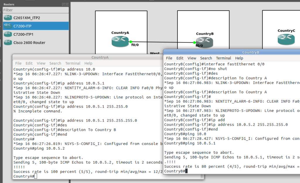
Let’s face it, if you’re reading this, I’m going to bet that you are probably aware of how to configure a router interface.
I’ve put a simple template down in the background to make a little more sense, which I’ve attached here if you want to follow along with the same addressing, etc.
So we’ll configure all the routers in each country with an IP – we don’t need to configure IP routing. This means adjacent countries with a direct connection between them should be able to ping each other, but separated countries shouldn’t be able to.
So now we’ve got IP connectivity between two countries, let’s get Sigtran / SS7 setup!
First we’ll need to define the basics, from configure-terminal in each of the Cisco STPs. We’ll need to set the SS7 variant (We’ll use ITU variant as we’re simulating international links), the network-indicator (This is an International network, so we’ll use that) and the point code for this STP (From the background image).
CountryA(config)#cs7 variant itu
CountryA(config)#cs7 network-indicator international
CountryA(config)#cs7 point-code 1.2.3
Repeat this step on Country A and Country B.
Next we’ll define a local peer on the STP. This is an instance of the Sigtran stack along with the port we’ll be listening on. Our remote peer will need to know this value to bring up the connection, the number specified is the port, and the IP is the IP it will bind on.
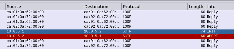
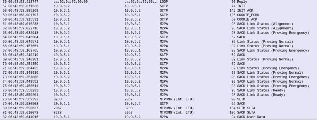
If you’re still sniffing the traffic between Country A and Country B, you should see our SS7 connection come up.
Wireshark trace of the connection coming up
The conneciton will come up layer-by-layer, firstly you’ll see the transport layer (SCTP) bring up an SCTP association, then MTP2 Peer Adaptation Layer (M2PA) will negotiate up to confirm both ends are working, then finally you’ll see MTP3 messaging.
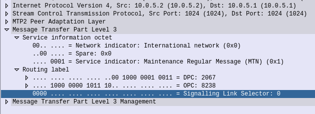
If we open up an MTP3 packet you can see our Originating and Destination Point Codes.
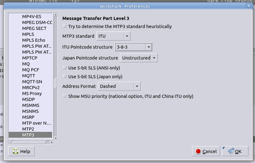
Notice in Wireshark the Point Codes don’t show up as 1-2-3, but rather 2067? That’s because they’re formatted as Decimal rather than 14 bit, this handy converter will translate them for you, or you can just change your preference in Wireshark’s decoders to use the matching ITU POint Code Structure.
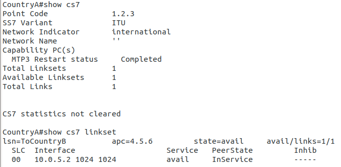
From the CLI on one of the two country STPs we can run some basic commands to view the status of all SS7 components and Linksets.
And there you have it! Basic SS7 connectivity!
There is so much more to learn, and so much more to do! By bringing up the link we’ve barely scratched the surface here.
Some homework before the next post, link all the other countries shown together, with Country D having a link to Country C and Country B. That’s where we’ll start in the lab – Tip: You’ll find you’ll need to configure a new cs7 local-peer for each interface, as each has its own IP.
This is part of a series of posts looking into SS7 and Sigtran networks. We cover some basic theory and then get into the weeds with GNS3 based labs where we will build real SS7/Sigtran based networks and use them to carry traffic.
So one more step before we actually start bringing up SS7 / Sigtran networks, and that’s to get a bit of a closer look at what components make up SS7 networks.
Recap: What is SS7?
SS7 is the name given to the protocol stack used almost exclusively in the telecommunications space. SS7 isn’t just one protocol, instead it is a suite of protocols. In the same way when someone talks about IP networking, they’re typically not just talking about the IP layer, but the whole stack from transport to application, when we talk about an SS7 network, we’re talking about the whole stack used to carry messages over SS7.
And what is SIGTRAN?
Sigtran is “Signaling Transport”. Historically SS7 was carried over TDM links (Like E1 lines).
As the internet took hold, the “Signaling Transport” working group was formed to put together the standards for carrying SS7 over IP, and the name stuck.
I’ve always thought if I were to become a Mexican Wrestler (which is quite unlikely), my stage name would be DSLAM, but SIGTRAN comes a close second.
Today when people talk about SIGTRAN, they mean “SS7 over IP”.
What is in an SS7 Network?
SS7 Networks only have 3 types of network elements:
Service Switching Points (SSP)
Service Transfer Points (STP)
Service Control Points (SCP)
Service Switching Points (SSP)
Service Switching Points (SSPs) are endpoints in the network. They’re the users of the connectivity, they use it to create and send meaningful messages over the SS7 network, and receive and process messages over the SS7 network.
Like a PC or server are IP endpoints on an IP Network, which send and receive messages over the network, an SSP uses the SS7 network to send and receive messages.
In a PSTN context, your local telephone exchange is most likely an SS7 Service Switching Point (SSP) as it creates traffic on the SS7 network and receives traffic from it.
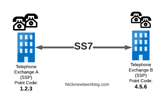
A call from a user on one exchange to a user on another exchange could go from the SSP in Exchange A, to the SSP in Exchange B, in the same way you could send data between two computers by connecting directly between them with an Ethernet crossover cable.
Messages between our two exchanges are addressed using Point Codes, which can be thought of a lot like IP Addresses, except shorter.
In the MTP3 header of each SS7 message is the Destination Point Code, and the Origin Point Code.
When Telephone Exchange A wants to send a message over SS7 to Telephone Exchange B, the MTP header would look like:
MTP3 Header:
Origin Point Code:      1.2.3
Destination Point Code: 4.5.6
Service Transfer Points (STP)
Linking each SSP to each other SSP has a pretty obvious problem as our network grows.
What happens if we’ve got hundreds of SSPs? If we want a full-mesh topology connecting every SSP to every other SSP directly, we’d have a rats nest of links!
A “full-mesh” approach for connecting SSPs does not work at scale, so STPs are introduced
So to keep things clean and scalable, we’ve got Signalling Transfer Points (STPs).
STPs can be thought of like Routers but in an SS7 network.
When our SSP generates an SS7 message, it’s typically handed to an STP which looks at the Destination Point Code, it’s own routing table and routes it off to where it needs to go.
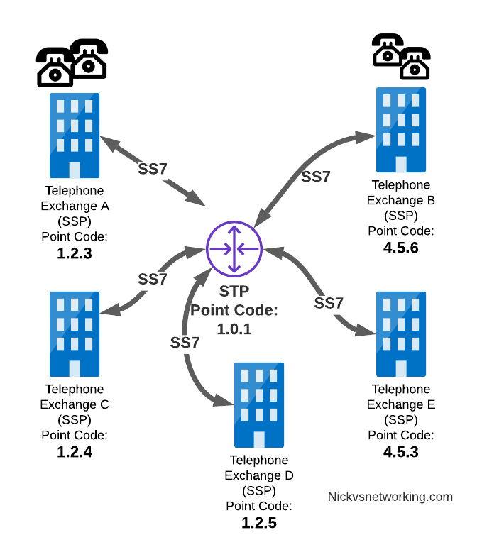
STP acting as a central router to connect lots of SSPs
This means every SSP doesn’t require a connection to every other SSP. Instead by using STPs we can cut down on the complexity of our network.
When Telephone Exchange A wants to send a message over SS7 to Telephone Exchange B, the MTP header would look the same, but the routing table on Telephone Exchange A would be setup to send the requests out the link towards the STP.
MTP3 Header:
Origin Point Code:      1.2.3
Destination Point Code: 4.5.6
Linksets
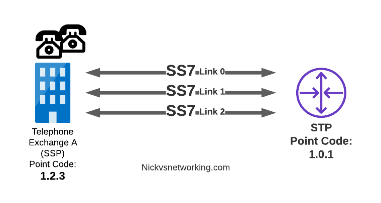
Between SS7 Nodes we have Linksets. Think of Linksets as like LACP or Etherchannel, but for SS7.
You want to have multiple links on every connection, for sharing out the load or for redundancy, and a Linkset is a group of connections from one SS7 node to another, that are logically treated as one link.
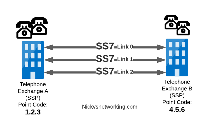
Link between an SSP and STP with 3 linksets
Each of the links in a Linkset is identified by a number, and specified in in the MTP3 header’s “Signaling Link Selector” field, so we know what link each message used.
MTP3 Header:
Origin Point Code:       1.2.3
Destination Point Code:  4.5.6
Signaling Link Selector: 2
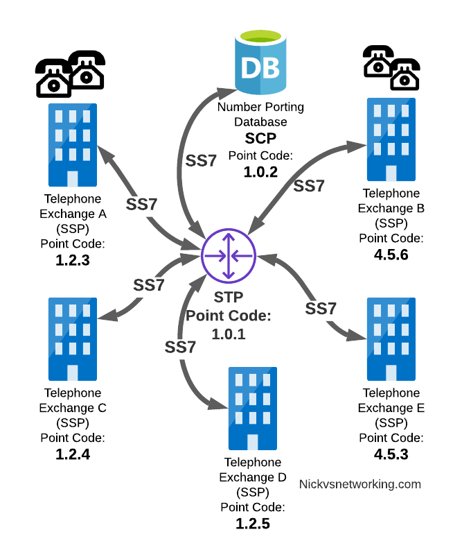
Service Control Point (SCP)
Somewhere between a Rolodex an relational database, is the Service Control Point (SCP).
For an exchange (SSP) to route a call to another exchange, it has to know the point code of the destination Exchange to send the call to. When fixed line networks were first deployed this was fairly straight forward, each exchange had a list of telephone number prefixes and the point code that served each prefix, simple.
But then services like number porting came along when a number could be moved anywhere. Then 1800/0800 numbers where a number had to be translated back to a standard phone number entered the picture.
To deal with this we need a database, somewhere an SSP can go to query some information in a database and get a response back.
This is where we use the Service Control Point (SCP).
Keep in mind that SS7 long predates APIs to easily lookup data from a service, so there was no RESTful option available in the 1980s.
When a caller on a local exchange calls a toll free (1800 or 0800 number depending on where you are) number, the exchange is setup with the Point Code of an SCP to query with the toll free number, and the SCP responds back with the local number to route the call to.
While SCPs are fading away in favor of technology like DNS/ENUM for Local Number Portability or Routing Databases, but they are still widely used in some networks.
Getting to know the Signalling Transfer Point (STP)
As we saw earlier, instead of a one-to-one connection between each SS7 device to every other SS7 device, Signaling Transfer Points (STP) are used, which act like routers for our SS7 traffic.
The STP has an internal routing table made up of the Point Codes it has connections to and some logic to know how to get to each of them.
Like a router, STPs don’t really create SS7 traffic, or consume traffic, they just receive SS7 messages and route them on towards their destination.
Ok, they do create some traffic for checking links are up, etc, but like a router, their main job is getting traffic where it needs to go.
When an STP receives an SS7 message, the STP looks at the MTP3 header. Specifically the Destination Point Code, and finds if it has a path to that Point Code. If it has a route, it forwards the SS7 message on to the next hop.
Like a router, an STP doesn’t really concern itself with anything higher than the MTP3 layer – As point codes are set in the MTP3 layer that’s the only layer the STP looks at and the upper layers aren’t really “any of its business”.
STPs don’t require a direct connection (Linkset) from the Originating Point Code straight to the Destination Point Code. Just like every IP router doesn’t need a direct connection to ever other network. By setting up a routing table of Point Codes and Linksets as the “next-hop”, we can reach Destination Point Codes we don’t have a direct Linkset to by routing between STPs to reach the final Destination Point Code.
Let’s work through an example:
And let’s look at the routing table setup on STP-A:
STP A Routing Table:
1.2.3 - Directly attached (Telephone Exchange A)
1.2.4 - Directly attached (Telephone Exchange C)
1.2.5 - Directly attached (Telephone Exchange D)
4.5.1 - Directly attached (STP-B)
4.5.3 - Via STP-B
4.5.6 - Via STP-B
So what happens when Telephone Exchange A (Point Code 1.2.3) wants to send a message to Telephone Exchange E (Point Code 4.5.3)? Firstly Telephone Exchange A puts it’s message on an MTP3 payload, and the MTP3 header will look something like this:
MTP3 Header:
Origin Point Code:       1.2.3
Destination Point Code:  4.5.3
Signaling Link Selector: 1
Telephone Exchange A sends the SS7 message to STP A, which looks at the MTP3 header’s Destination Point Code (4.5.3), and then in it’s routing table for a route to the destination point. We can see from our example routing table that STP A has a route to Destination Point Code 4.5.3 via STP-B, so sends it onto STP-B.
For STP-B it has a direct connection (linkset) to Telephone Exchange E (Point Code 4.5.3), so sends it straight on
Like IP, Point Codes have their own form of Variable-Length-Subnet-Routing which means each STP doesn’t need full routing info for every Destination Point Code, but instead can have routes based on part of the point code and a subnet mask.
But unlike IP, there is no BGP or OSPF on SS7 networks. Instead, all routes have to be manually specified.
For STP A to know it can get messages to destinations starting with 4.5.x via STP B, it needs to have this information manually added to it’s route table, and the same for the return routing.
Sigtran & SS7 Over IP
As the world moved towards IP enabled everything, TDM based Sigtran Networks became increasingly expensive to maintain and operate, so a IETF taskforce called SIGTRAN (Signaling Transport) was created to look at ways to move SS7 traffic to IP.
When moving SS7 onto IP, the first layer of SS7 (MTP1) was dropped, as it primarily concerned the physical side of the network. MTP2 didn’t really fit onto an IP model, so a two options were introduced for transport of the MTP2 data, M2PA (Message Transfer Part 2 User Peer-to-Peer Adaptation Layer) and M2UA (MTP2 User Adaptation Layer) were introduced, which rides on top of SCTP. This means if you wanted an MTP2 layer over IP, you could use M2UA or M2TP.
SCTP is neither TCP or UDP. I’ve touched upon SCTP on this blog before, it’s as if you took the best bits of TCP without the issues like head of line blocking and added multi-homing of connections.
So if you thought all the layers above MTP2 are just transferred, unchanged on top of our M2PA layer, that’s one way of doing it, however it’s not the only way of doing it.
There are quite a few ways to map SS7 onto IP Networks, which we’ll start to look into it more detail, but to keep it simple, for the next few posts we’ll be assuming that everything above MTP2/M2PA remain unchanged.
In the next post, we’ll get some actual SS7 traffic flowing!
This is part of a series of posts looking into SS7 and Sigtran networks. We cover some basic theory and then get into the weeds with GNS3 based labs where we will build real SS7/Sigtran based networks and use them to carry traffic.
If you use a mobile phone, a VoIP system or a copper POTS line, there’s a high chance that somewhere in the background, SS7 based signaling is being used.
The signaling for GSM, UMTS and WCDMA mobile networks all rely on SS7 based signaling, and even today the backbone of most PSTN traffic relies SS7 networks. To many this is mysterious carrier tech, and as such doesn’t get much attention, but throughout this series of posts we’ll take a hands-on approach to putting together an SS7 network using GNS3 based labs and connect devices through SS7 and make some stuff happen.
Overview of SS7
Signaling System No. 7 (SS7/C7) is the name for a family of protocols originally designed for signaling between telephone switches. In plain English, this means it was used to setup and teardown large volumes of calls, between exchanges or carriers.
When carrier A and Carrier B want to send calls between each other, there’s a good chance they’re doing it over an SS7 Network.
But wait! SIP exists and is very popular, why doesn’t everyone just use SIP? Good question, imaginary asker. The answer is that when SS7 came along, SIP was still almost 25 years away from being defined. Yes. It’s pretty old.
SS7 isn’t one protocol, but a family of protocols that all work together – A “protocol stack”. The SS7 specs define the lower layers and a choice of upper layer / application protocols that can be carried by them.
The layered architecture means that the application layer at the top can be changed, while the underlying layers are essentially the same.
This means while SS7’s original use was for setting up and tearing down phone calls, this is only one application for SS7 based networks. Today SS7 is used heavily in 2G/3G mobile networks for connectivity between core network elements in the circuit-switched domain, for international roaming between carriers and services like Local Number Portability and Toll Free numbers.
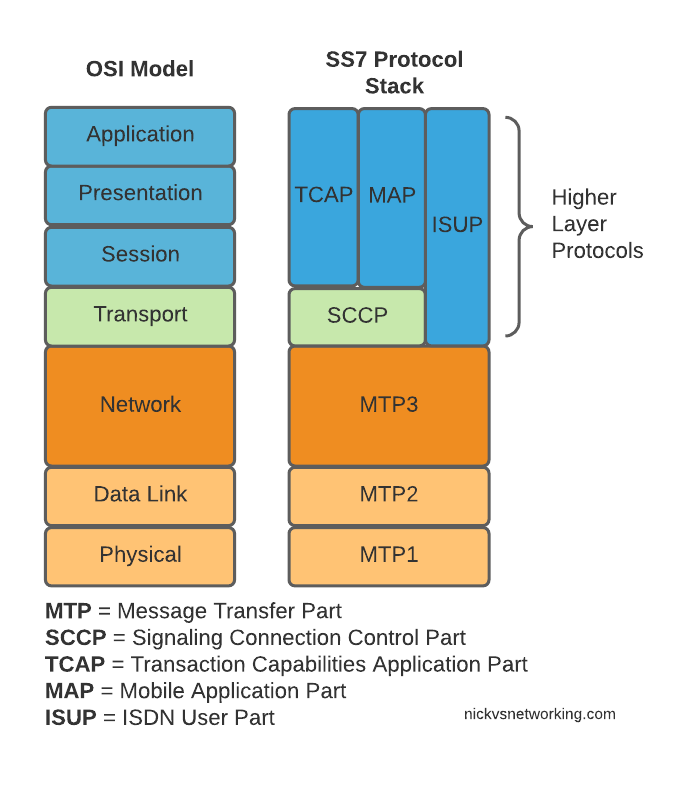
Here’s the layers of SS7 loosely mapped onto the OSI model (SS7 predates the OSI model as well):
OSI Model (Left) and SS7 Protocol Stack (Right)
We do have a few layers to play with here, and we’ll get into them all in depth as we go along, but a brief introduction to the underlying layers:
MTP 1 – Message Transfer Part 1
This is our physical layer. In this past this was commonly E1/T1 lines.
It’s responsible for getting our 1s and 0s from one place to another.
MTP 2 – Message Transfer Part 2
MTP2 is responsible for the data link layer, handling reliable transfer of data, in sequence.
MTP 3 – Message Transfer Part 3
The MTP3 header contains an Originating and a Destination Point Code.
These point codes can be thought of as like an IP Address; they’re used to address the source and destination of a message. A “Point Code” is the unique address of a SS7 Network element.
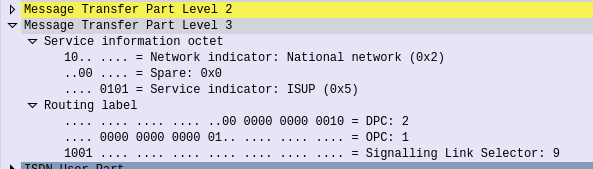
MTP3 header showing the Destination Point Code (DPC) and Origin Point Code (OPC) on a National Network, carrying ISUP traffic
Every message sent over an SS7 network will contain an Origin Point Code that identifies the sender, and a Destination Point Code that identifies the intended recipient.
This is where we’ll bash around at the start of this course, setting up Linksets to allow different devices talking to each other and addressing each other via Point Codes.
The MTP3 header also has a Service Indicator flag that indicates what the upper layer protocol it is carrying is, like the Protocol indicator in IPv4/IPv6 headers.
A Signaling Link Selector indicates which link it was transported over (did I mention we can join multiple links together?), and a Network Indicator for determining if this is signaling is at the National or International level.
TUP/MAP/SCCP/ISUP
These are the “higher-layer” protocols. Like FTP sits on top of TCP/IP, a SS7 network can transport these protocols from their source to their destination, as identified by the Origin Point Code (OPC), to the Destination Point Code (DPC), as specified in the MTP3 header.
We’ll touch on these protocols more as we go on. SCCP has it’s own addressing on top of the OPC/DPC (Like IP has IP Addressing, but TCP has port numbers on top to further differentiate).
Why learn SS7 today?
SS7 and SIGTRAN are still widely in use in the telco world, some of it directly, other parts derived / evolved from it.
So stick around, things are about to get interesting!