This is part of a series of posts looking into SS7 and Sigtran networks. We cover some basic theory and then get into the weeds with GNS3 based labs where we will build real SS7/Sigtran based networks and use them to carry traffic.
Having a direct Linkset from every Point Code to every other Point Code in an SS7 network isn’t practical, we need to rely on routing, so in this post we’ll cover routing between Point Codes on our STPs.
Let’s start in the IP world, imagine a router with a routing table that looks something like this:
Simple IP Routing Table
192.168.0.0/24 out 192.168.0.1 (Directly Attached)
172.16.8.0/22 via 192.168.0.3 - Static Route - (Priority 100)
172.16.0.0/16 via 192.168.0.2 - Static Route - (Priority 50)
10.98.22.1/32 via 192.168.0.3 - Static Route - (Priority 50)
We have an implicit route for the network we’re directly attached to (192.168.0.0/24), and then a series of static routes we configure.
We’ve also got two routes to the 172.16.8.0/22 subnet, one is more specific with a higher priority (172.16.8.0/22 – Priority 100), while the other is less specific with a lower priority (172.16.0.0/16 – Priority 50). The higher priority route will take precedence.
This should look pretty familiar to you, but now we’re going to take a look at routing in SS7, and for that we’re going to be talking Variable Length Subnet Masking in detail you haven’t needed to think about since doing your CCNA years ago…
Why Masking is Important
A route to a single Point Code is called a “/14”, this is akin to a single IPv4 address being called a “/32”.
We could setup all our routing tables with static routes to each point code (/14), but with about 4,000 international point codes, this might be a challenge.
Instead, by using Masks, we can group together ranges of Point Codes and route those ranges through a particular STP.
This opens up the ability to achieve things like “Route all traffic to Point Codes to this Default Gateway STP”, or to say “Route all traffic to this region through this STP”.
Individually routing to a point code works well for small scale networking, but there’s power, flexibility and simplification that comes from grouping together ranges of point codes.
Information Overload about Point Codes
So far we’ve talked about point codes in the X.YYY.Z format, in our lab we setup point codes like 1.2.3.
This is not the only option however…
Variants of SS7 Point Codes
IPv4 addresses look the same regardless of where you are. From Algeria to Zimbabwe, IPv4 addresses look the same and route the same.

In SS7 networks that’s not the case – There are a lot of variants that define how a point code is structured, how long it is, etc. Common variants are ANSI, ITU-T (International & National variants), ETSI, Japan NTT, TTC & China.
The SS7 variant used must match on both ends of a link; this means an SS7 node speaking ETSI flavoured Point Codes can’t exchange messages with an ANSI flavoured Point Code.
Well, you can kinda translate from one variant to another, but requires some rewriting not unlike how NAT does it.
ITU International Variant
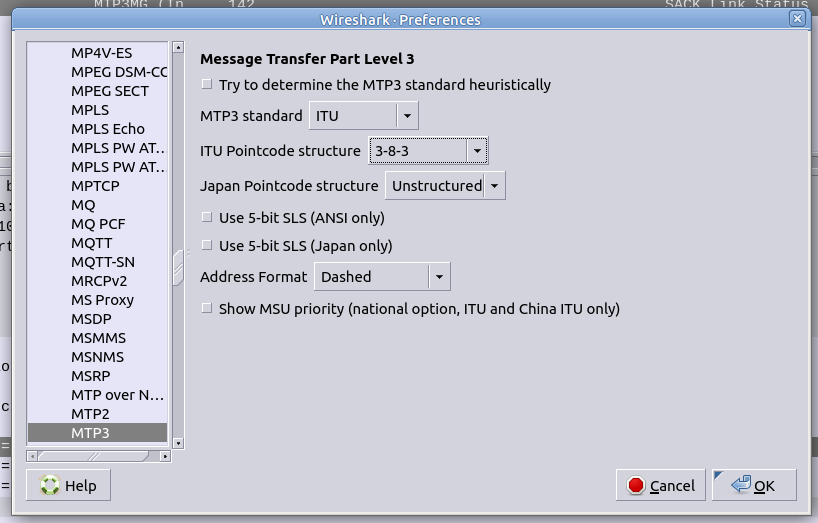
For the start of this series, we’ll be working with the ITU International variant / flavour of Point Code.
ITU International point codes are 14 bits long, and format is described as 3-8-3.
The 3-8-3 form of Point code just means the 14 bit long point code is broken up into three sections, the first section is made up of the first 3 bits, the second section is made up of the next 8 bits then the remaining 3 bits in the last section, for a total of 14 bits.
So our 14 bit 3-8-3 Point Code looks like this in binary form:
000-00000000-000 (Binary) == 0-0-0 (Point Code)
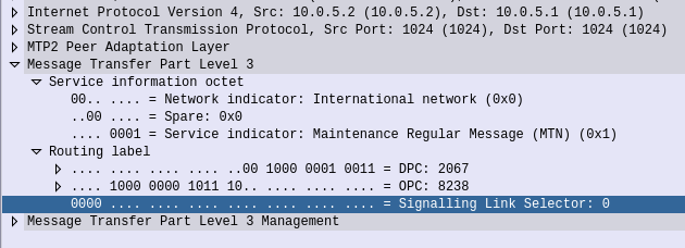
So a point code of 1-2-3 would look like:
001-00000010-011 (Binary) == 1-2-3 (Point Code) [001 = 1, 00000010 = 2, 011 = 3]
This gives us the following maximum values for each part:
111-11111111-111 (Binary) == 7-255-7 (Point Code)
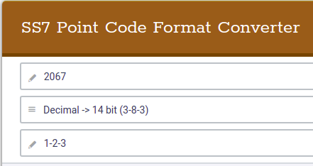
This is not the only way to represent point codes, if we were to take our binary string for 1-2-3 and remove the hyphens, we get 00100000010011. If you convert this binary string into an Integer/Decimal value, you’ll get 2067.
If you’re dealing with multiple vendors or products,you’ll see some SS7 Point Codes represented as decimal (2067), some showing as 1-2-3 codes and sometimes just raw binary.
Fun hey?
Why we need to know about Binary and Point Codes
So why does the binary part matter? Well the answer is for masks.
To loop back to the start of this post, we talked about IP routing using a network address and netmask, to represent a range of IP addresses. We can do the same for SS7 Point Codes, but that requires a teeny bit of working out.
As an example let’s imagine we need to setup a route to all point codes from 3-4-0 through to 3-6-7, without specifying all the individual point codes between them.
Firstly let’s look at our start and end point codes in binary:
100-00000100-000 = 3-004-0 (Start Point Code)
100-00000110-111 = 3-006-7 (End Point Code)
Looking at the above example let’s look at how many bits are common between the two,
100-00000100-000 = 3-004-0 (Start Point Code)
100-00000110-111 = 3-006-7 (End Point Code)
The first 9 bits are common, it’s only the last 5 bits that change, so we can group all these together by saying we have a /9 mask.
When it comes time to add a route, we can add a route to 3-4-0/9 and that tells our STP to match everything from point code 3-4-0 through to point code 3-6-7.
The STP doing the routing it only needs to match on the first 9 bits in the point code, to match this route.
SS7 Routing Tables
Now we have covered Masking for roues, we can start putting some routes into our network.
In order to get a message from one point code to another point code, where there isn’t a direct linkset between the two, we need to rely on routing, which is performed by our STPs.
This is where all that point code mask stuff we just covered comes in.
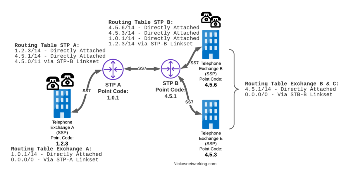
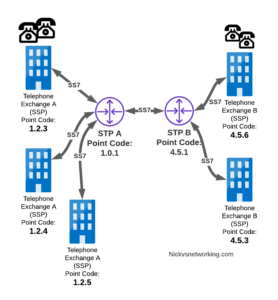
Let’s look at a diagram below,
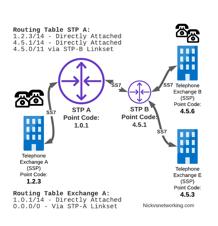
Let’s look at the routing to get a message from Exchange A (SSP) on the bottom left of the picture to Exchange E (SSP) with Point Code 4.5.3 in the bottom right of the picture.
Exchange A (SSP) on the bottom left of the picture has point code 1.2.3 assigned to it and a Linkset to STP-A.
It has the implicit route to STP-A as it’s got that linkset, but it’s also got a route configured on it to reach any other point code via the Linkset to STP-A via the 0.0.0/0 route which is the SS7 equivalent of a default route. This means any traffic to any point code will go to STP-A.
From STP-A we have a linkset to STP-B. In order to route to the point codes behind STP-B, STP-A has a route to match any Point Code starting with 4.5.X, which is 4.5.0/11.
This means that STP-A will route any Point Code between 4.5.1 and 4.5.7 down the Linkset to STP-B.
STP-B has got a direct connection to Exchange B and Exchange E, so has implicit routes to reach each of them.
So with that routing table, Exchange A should be able to route a message to Exchange E.
But…
Return Routing
Just like in IP routing, we need return routing. while Exchange A (SSP) at 1.2.3 has a route to everywhere in the network, the other parts of the network don’t have a route to get to it. This means a request from 1.2.3 can get anywhere in the network, but it can’t get a response back to 1.2.3.
So to get traffic back to Exchange A (SSP) at 1.2.3, our two Exchanges on the right (Exchange B & C with point codes 4.5.6 and 4.5.3) will need routes added to them. We’ll also need to add routes to STP-B, and once we’ve done that, we should be able to get from Exchange A to any point code in this network.

There is a route missing here, see if you can pick up what it is!
So we’ve added a default route via STP-B on Exchange B & Exchange E, and added a route on STP-B to send anything to 1.2.3/14 via STP-A, and with that we should be able to route from any exchange to any other exchange.
One last point on terminology – when we specify a route we don’t talk in terms of the next hop Point Code, but the Linkset to route it down. For example the default route on Exchange A is 0.0.0/0 via STP-A linkset (The linkset from Exchange A to STP-A), we don’t specify the point code of STP-A, but just the name of the Linkset between them.
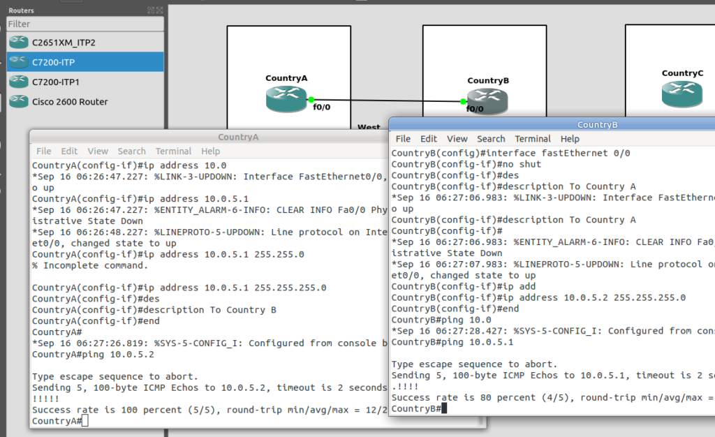
Back into the Lab
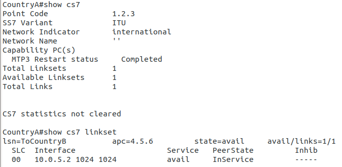
So back to the lab, where we left it was with linksets between each point code, so each Country could talk to it’s neighbor.
Let’s confirm this is the case before we go setting up routes, then together, we’ll get a route from Country A to Country C (and back).
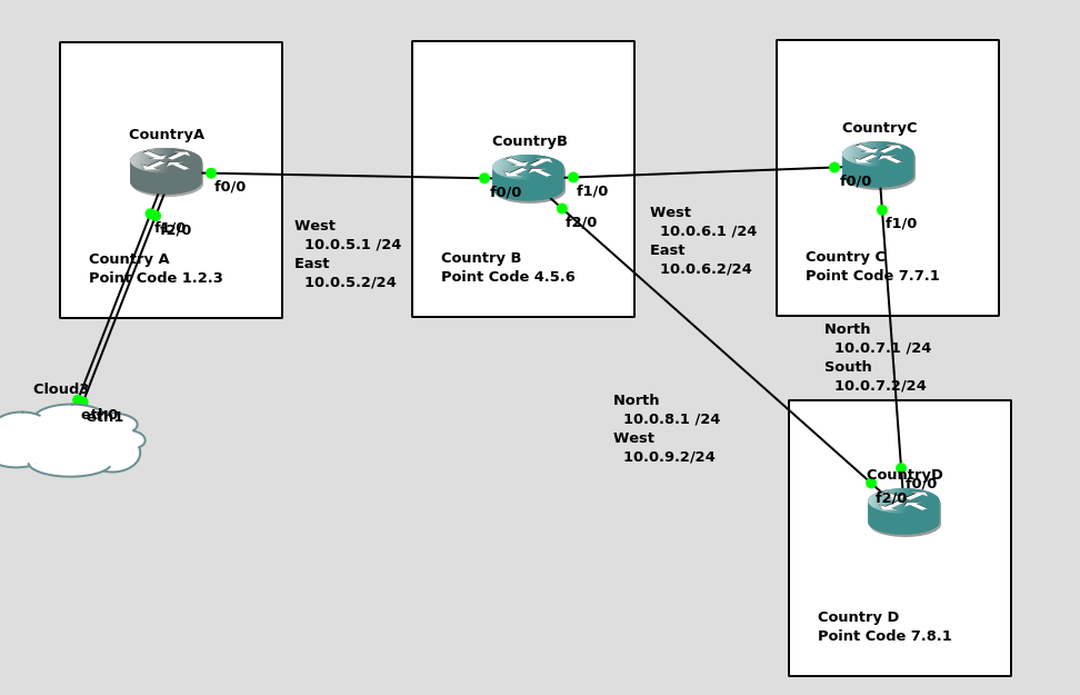
So let’s check the status of the link from Country B to its two neighbors – Country A and Country C. All going well it should look like this, and if it doesn’t, then stop by my last post and check you’ve got everything setup.
CountryB#show cs7 linkset
lsn=ToCountryA          apc=1.2.3         state=avail     avail/links=1/1
  SLC  Interface                    Service   PeerState         Inhib
  00   10.0.5.1 1024 1024           avail     InService         -----

lsn=ToCountryC          apc=7.7.1         state=avail     avail/links=1/1
  SLC  Interface                    Service   PeerState         Inhib
  00   10.0.6.2 1025 1025           avail     InService         -----
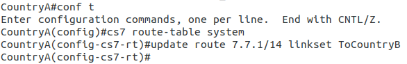
So let’s add some routing so Country A can reach Country C via Country B. On Country A STP we’ll need to add a static route. For this example we’ll add a route to 7.7.1/14 (Just Country C).
That means Country A knows how to get to Country C. But with no return routing, Country C doesn’t know how to get to Country A. So let’s fix that.
We’ll add a static route to Country C to send everything via Country B.
CountryC#conf t
Enter configuration commands, one per line.  End with CNTL/Z.
CountryC(config)#cs7 route-table system
CountryC(config)#update route 0.0.0/0 linkset ToCountryB
*Jan 01 05:37:28.879: %CS7MTP3-5-DESTSTATUS: Destination 0.0.0 is accessible
So now from Country C, let’s see if we can ping Country A (Ok, it’s not a “real” ICMP ping, it’s a link state check message, but the result is essentially the same).
By running:
CountryC# ping cs7 1.2.3
*Jan 01 06:28:53.699: %CS7PING-6-RTT: Test Q.755 1.2.3: MTP Traffic test rtt 48/48/48
*Jan 01 06:28:53.699: %CS7PING-6-STAT: Test Q.755 1.2.3: MTP Traffic test 100% successful packets(1/1)
*Jan 01 06:28:53.699: %CS7PING-6-RATES: Test Q.755 1.2.3: Receive rate(pps:kbps) 1:0 Sent rate(pps:kbps) 1:0
*Jan 01 06:28:53.699: %CS7PING-6-TERM: Test Q.755 1.2.3: MTP Traffic test terminated.
We can confirm now that Country C can reach Country A, we can do the same from Country A to confirm we can reach Country B.
But what about Country D? The route we added on Country A won’t cover Country D, and to get to Country D, again we go through Country B.
This means we could group Country C and Country D into one route entry on Country A that matches anything starting with 7-X-X,
For this we’d add a route on Country A, and then remove the original route;
CountryA(config)# cs7 route-table system
CountryA(config-cs7-rt)#update route 7.0.0/3 linkset ToCountryB
CountryA(config-cs7-rt)#no update route 7.7.1/14 linkset ToCountryB
Of course, you may have already picked up, we’ll need to add a return route to Country D, so that it has a default route pointing all traffic to STP-B. Once we’ve done that from Country A we should be able to reach all the other countries:
CountryA#show cs7 route
Dynamic Routes 0 of 1000

Routing table = system Destinations = 3 Routes = 3

Destination            Prio Linkset Name        Route
---------------------- ---- ------------------- -------
4.5.6/14         acces   1  ToCountryB          avail
7.0.0/3          acces   5  ToCountryB          avail


CountryA#ping cs7 7.8.1
*Jan 01 07:28:19.503: %CS7PING-6-RTT: Test Q.755 7.8.1: MTP Traffic test rtt 84/84/84
*Jan 01 07:28:19.503: %CS7PING-6-STAT: Test Q.755 7.8.1: MTP Traffic test 100% successful packets(1/1)
*Jan 01 07:28:19.503: %CS7PING-6-RATES: Test Q.755 7.8.1: Receive rate(pps:kbps) 1:0  Sent rate(pps:kbps) 1:0
*Jan 01 07:28:19.507: %CS7PING-6-TERM: Test Q.755 7.8.1: MTP Traffic test terminated.
CountryA#ping cs7 7.7.1
*Jan 01 07:28:26.839: %CS7PING-6-RTT: Test Q.755 7.7.1: MTP Traffic test rtt 60/60/60
*Jan 01 07:28:26.839: %CS7PING-6-STAT: Test Q.755 7.7.1: MTP Traffic test 100% successful packets(1/1)
*Jan 01 07:28:26.839: %CS7PING-6-RATES: Test Q.755 7.7.1: Receive rate(pps:kbps) 1:0  Sent rate(pps:kbps) 1:0
*Jan 01 07:28:26.843: %CS7PING-6-TERM: Test Q.755 7.7.1: MTP Traffic test terminated.
So where to from here?
Well, we now have a a functional SS7 network made up of STPs, with routing between them, but if we go back to our SS7 network overview diagram from before, you’ll notice there’s something missing from our lab network…
So far our network is made up only of STPs, that’s like building a network only out of routers!
In our next lab, we’ll start adding some SSPs to actually generate some SS7 traffic on the network, rather than just OAM traffic.