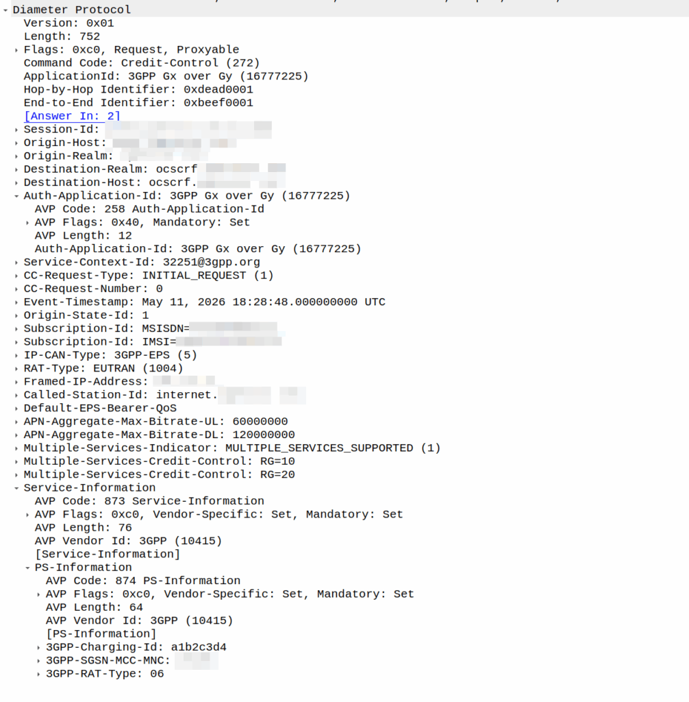
I was recently asked by a potential customer if we supported Gx over Gy.
I’d never heard of this before, so I gave my standard “If it’s in the spec we should support it, but I’ll check” answer, and got them to send me a PCAP, which I’ve got.
This is weird.
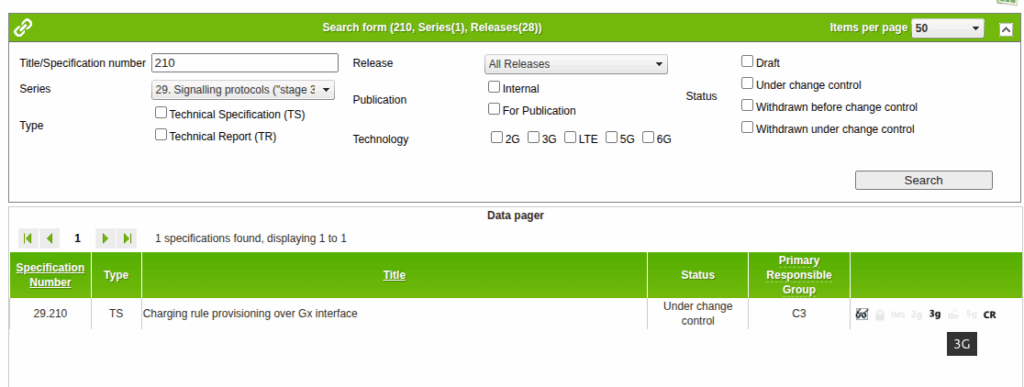
So for starers, Protocoldex has nothing for this application ID (16777225), even though it has all the LTE diameter specs.
The last version was from 2006, in 3GPP release 6, which is two years before LTE was standardized in Release 8. The word LTE does not appear in the doc or in the metadata tags.
It speaks of TPF (Traffic Plane Function) and TPF (Charging Rules Function).
LTE is “Long Term Evolution” – In later releases this draft TPF would evolve into the PGW (before the PGW-C / PGW-U divorce) and the TPF would go on to become the PCRF (and save spring break).
Reading through these early specs is like looking at Homo Eructs (get your mind out of the gutter) and knowing it evolves into Homo Sapiens.
So what does Gx over Gy do? Well, the concept is pretty straightforward, rather than needing a Sy interface between the PCRF and OCS, you can provision policy rules from the OCS, rather than on the PCRF.
So what network functions should implement this standard? Well, the P-GW specs do not reference this as something that’s included in the P-GW, nor is it in the GGSN – This was a “gooch” spec between the hypothetical standards land and real world implementations.
So will we be implementing it? Probably not. But an interesting bit of archaeology and a look through the genealogy of 3GPP.
There’s a cool feature in PFCP that allows you to redirect traffic, which I’ve written about before.
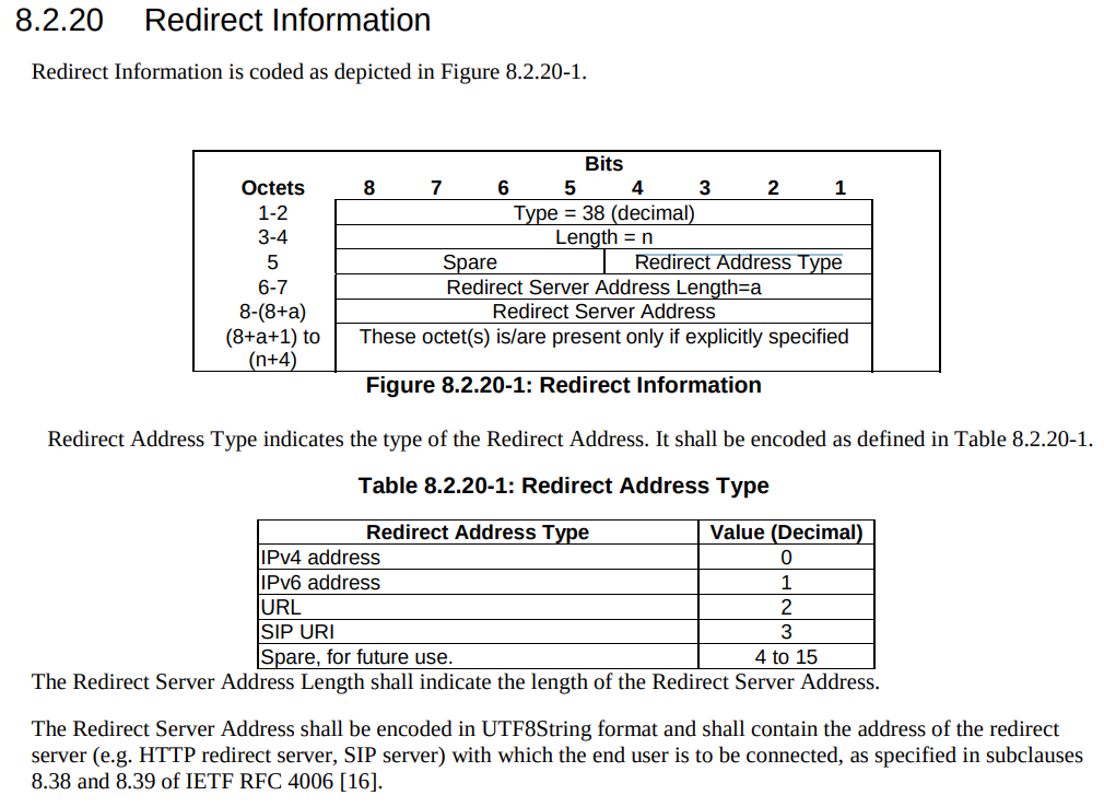
But there’s a funky thing that’s left me scratching my head, in the Redirect information IE, you can set a SIP URI.
Snippet from TS 3GPP TS 29.244
That’d be great and all, but PFCP is all about packets not about calls.
So what’s the deal?
Had I uncovered some Machiavellian plot to move channel-associated-signaling onto PFCP instead of TDM links as God intended?
Well, no…
The Redirect Information in PFCP comes from the Redirect Information in Diameter, that’s how your OCS can tell your SMF or your PGW-C (or your TAS) – hey this session is all out of usage, and should be redirected.
Of course, PFCP is just all about packets, but Diameter has a foot in both camps, Gy and Ro are both on Diameter.
PFCP includes a “Redirect Information” IE, which if set, allows you to change the forwarding action in PFCP to Redirect traffic.
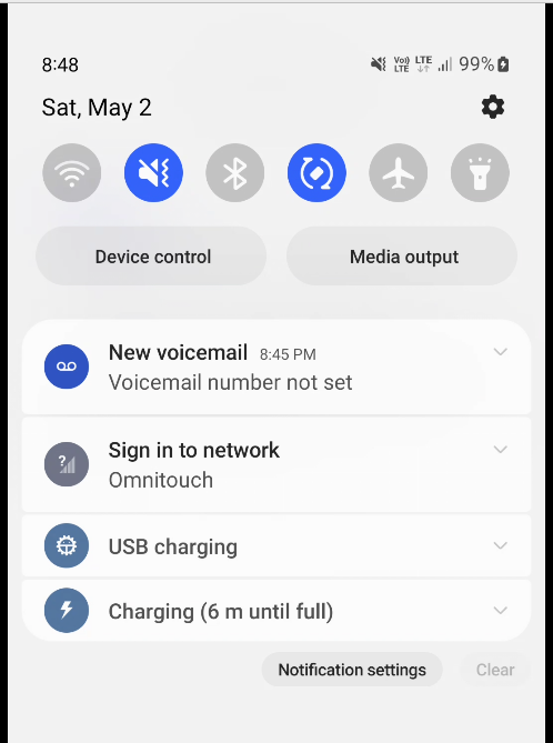
We use this for walled garden redirects, when the OCS reports credit exhausted to the PGW-C, the PGW-C can tell the UPF (PGW-U) that all the traffic from a given subscriber should be redirected to a captive portal / walled garden, like a “Topup Now Page” you’d be used to seeing on Airport WiFi.
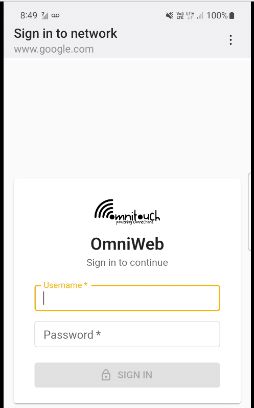
“Sign in to network” prompt presented on Cellular
Here’s what the spec says:
8.37. Redirect-Server AVP The Redirect-Server AVP (AVP Code 434) is of type Grouped and contains the address information of the redirect server (e.g., HTTP redirect server, SIP Server) with which the end user is to be connected when the account cannot cover the service cost. It MUST be present when the Final-Unit-Action AVP is set to REDIRECT. It is defined as follows (per the grouped-avp-def of RFC 3588 [DIAMBASE]): Redirect-Server ::= < AVP Header: 434 > { Redirect-Address-Type } { Redirect-Server-Address }
So how does this work in practice?
Once upon a time, you’d just intercept all HTTP request and serve your own content, but it’s not 2005 on Starbucks WiFi anymore, and SSL is everywhere.
Luckily this is a (mostly) solved problem, Apple has “Captive Network Assistant” that probes http://captive.apple.com/hotspot-detect.html and checks for a specific response, Google’s Android has http://connectivitycheck.gstatic.com/generate_204 and does the same thing.
But before I can tell you what we do, I’ll show you what we’re not doing before we do the doing so you can see what the do does by looking at what happens when we don’t – Clear?
Before we send any Session Modification Request with redirect I can do a DNS lookup, here’s an example from our test jig that goes to Facebook:
A Record lookup for facebook.com resolving to 57.145.8.1
This is just a regular A record DNS query wrapped up in GTP-U as it’d look from a eNB/gNB/SGW that gets an answer back also in GTP-U.
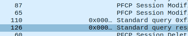
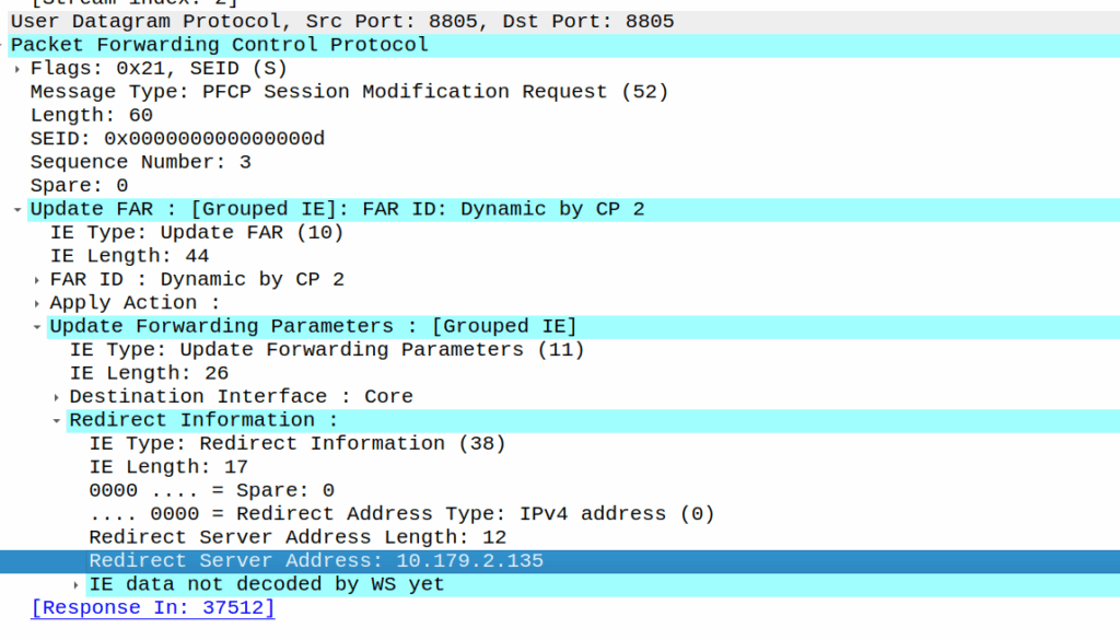
As we’ve already got a session up in our case, the SMF or PGW-C we sends the PFCP Session Modification Request I shared in the screenshot earlier to the UPF.
The Redirect Server Address in the Redirect Information IE in PFCP
We do a few things on the UPF at this point, the first, is that we block forwarding access to all IPs except 10.179.2.135 (The redirect server in the screenshot), and we steal / intercept all DNS queries.
This means if you query facebook.com after the Redirect Information is in place, you get back an A-Record answer for facebook.com but it’s telling you Facebook lives on our redirect server.
We’ve got a whitelist on our UPF for certain domains, so if we’re sending you to a self-signup page, you’re going to need to be able to hit our payment processors portals (Stripe, Paypal, etc), so we need to allow their domains, but we don’t know their IPs, so instead we do server side DNS lookups (via our DNS servers before you sneaky kids get any other ideas) for the whitelsited domains, and if it’s on our DNS whitelist, we allow resolution to those domains and allow access to those IPs returned in the DNS response.
In my lab I’m redirecting HTTP traffic to a management server
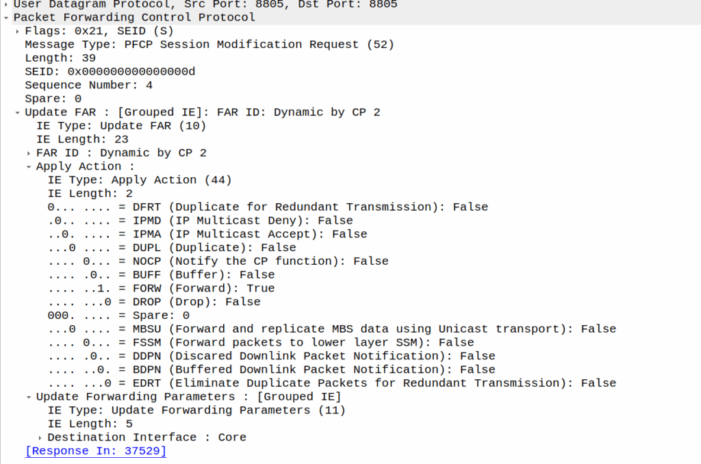
Turning it off just involves sending another PFCP Session Modification Request but without the redirect information.
This is an idea I’ve been kicking around for a little while – A single GSM TRX being broadcast across multiple cell sites.
Generally in GSM land, a “TRX” is a cell or a sector – but it doesn’t need to be. Later in GSM features like antenna diversity allow the same signal to be broadcast out multiple ports and received on multiple ports, and these to even work together.
Knowing this is possible, what if you run a single TRX across multiple cells / sectors / sites?
This means rather than cell site A & cell site B being “neighbors” they’re a single TRX. A subscriber moving between the two sees the same LAC and Cell ID, but they see the signal strength drop and then rise as they move between the cells, but there’s no “handover” – it’d look to the phone the same as going away from a cell then coming closer, which is what they’ve done, but the cell is being broadcast from two locations.
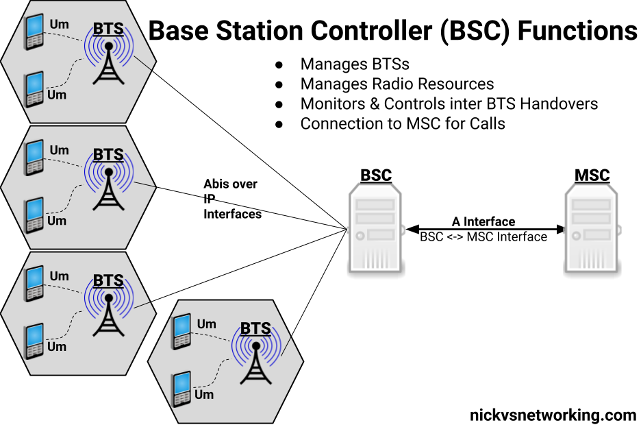
So why do this? Well, while VoLTE is nice, handset support on low end feature phones is still shite, and it means in some of the places we operate we couldn’t capture the low end of the market – those who just needed a basic voice service. As such we’ve finallyadded an MSC to our product offering (after almost 10 years of me swearing there’s no way we’d build legacy crap) and a BSC that’s compatible with our existing RAN portfolio (Nokia Airscale), all to be able to address that gap, by running a small GSM layer off our existing radios.
The capacity would be shared of course – this is just one TRX, so 8 full rate channels, but for our use of CSFB for feature phones, garbage IoT devices, it doesn’t matter. On spectral efficiency this is way better than a 5Mhz UMTS carrier (smallest you can do) and co-exists nicely with LTE.
Running a large number of sectors / cells on a common single TRX means when you’ve got a boundary where you need to hand to another TRX, you need fewer channels your reuse pattern. Even running 3 TRXes in our “Super cell” area, is only 600Khz of bandwidth consumed, and if the area is large enough we can do a ~3:1 reuse pattern.
For this to work we’ve got to serve all the cells of a single baseband, but baseband hotels are becoming the norm, and fiber is everywhere. I did start exploring if we could do one TRX on multiple BTSes on our BSC, from an Abis perspective it’d work, but we’d need to ensure timing and I don’t know enough about how the clocking works on our BTSes to say for sure that they’d be in sync even with GLONASS/GPS.
Would this work at scale? I’ve no idea, but I’m hoping to find out!
I do a lot of protocol testing, writing Diameter/PFCP/GTP-C etc, and spend a lot of time referencing the standards.
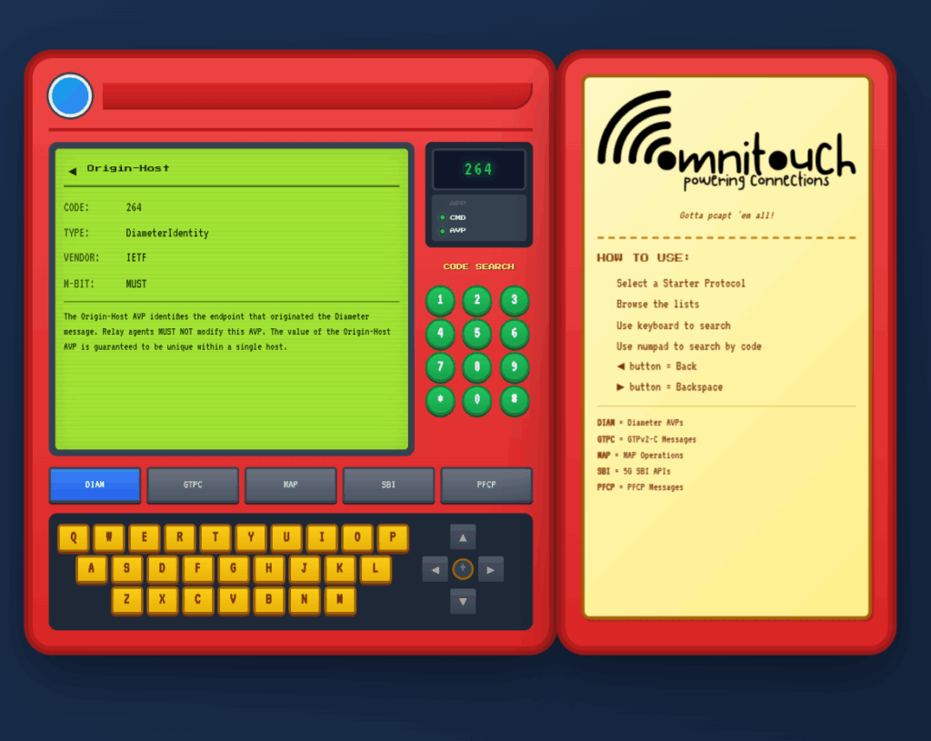
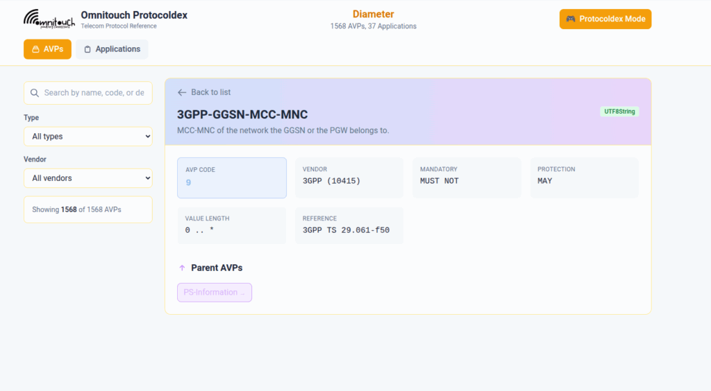
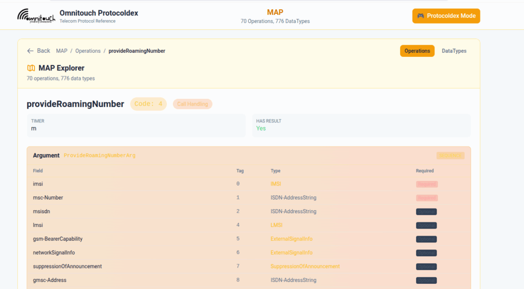
So I built this – Inspired by a 1990s video game / TV / Playing card franchise online reference tool, but rather than identifying pocket monsters, it’s identifying AVPs and stuff
You can punch in the AVP code, AVP name, description, etc, for Diameter, PFCP, GTP-C, MAP or SBI and see all the details to go with it.
I’ve been using it a heap, hopefully some of you might find it useful:
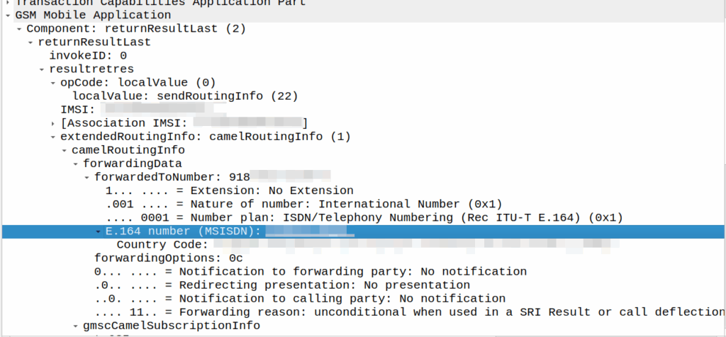
I’ve covered how SS7/ISUP handles call forward before, but the HLR can also store call forwarding information.
This is returned to the MSC when the SendRoutingInfo dialog is performed against the HLR.
If it’s present the MSC will redirect the call to that destination, after bouncing it through CAMEL (if enabled).
A lot simpler than Call Forward in IMS, but same outcome.
A lot of HSSes we see are just HLRs under the hood and only implement a minimalist MMTel feature set for call forwarding for this reason to have it track across both.
Here’s a Kamailio question I posed to the mailing list the other day:
I’m working on a scenario with a Kamailio box with a private IP, with a public IP 1:1 NATed to it (but the VM does not see the public IP on the NICs).
When forwarding requests to some hosts I want to set the Via address to be the public IP, but when forwarding requests to other hosts I want to leave the Via address to the internal IP address.
If I set the Advertise parameter in the bind config, this sets the Via to the advertised IP, but I’m seeing that address used even when communicating with hosts on the private IP.
Of course if the IP was on the VM itself I could use $fs or force_send_socket, but that only works if I’ve got the public IP bound, which I can’t do.
Is there a simple way to set / override what IP gets baked into the Via header?
Where you’ve got multiple IPs on your box, you can include the advertise paramter to override the IP you show, for example if you have the IP 100.64.253.251 on your NIC, but you’ve NATed the traffic and instead want to show 1.2.3.4 you can set this in the general config:
But then every message Kamailio forwards, will contain the 1.2.3.4 address int he Via header. For my scenario, this didn’t work, as I wanted to only use the 1.2.3.4 IP when communicating with hosts outside of the RFC1918 address space (only conditionally use that address).
Because of this I couldn’t use the advertise option, but I found the set_advertised_address() function to use in my routing logic, where I set the advertised address just on the given routes I care about:
#General Config:
listen=tcp:100.64.253.251:5061


#My routing blocks that go to hosts outside RFC1918 address space:
                rtpengine_manage("media-address=1.2.3.4");
                set_advertised_address("1.2.3.4:5060");
                msg_apply_changes();
So now any packets by default will have a Via of 100.64.253.251 but when I want to I can set the Via to the 1.2.3.4 public IP (and I do the same in RTPengine).
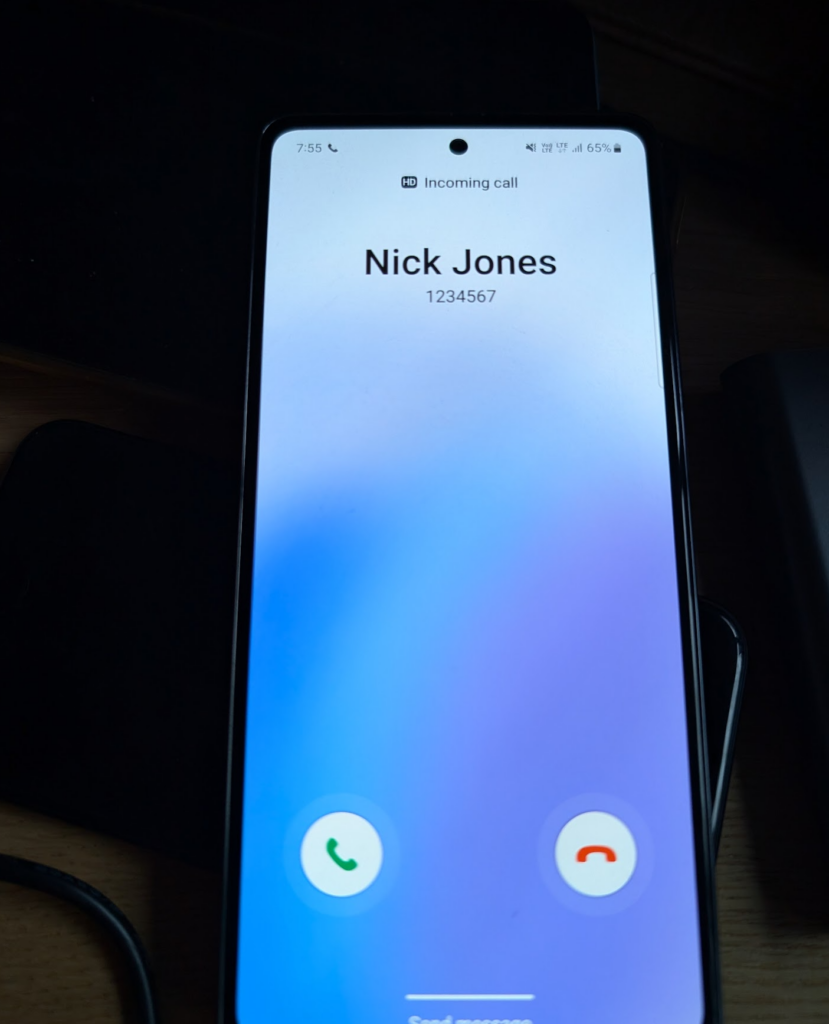
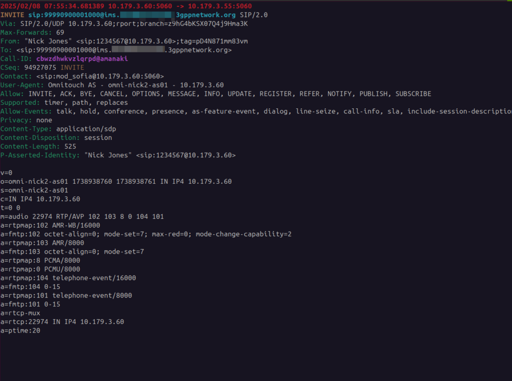
SIP has got a multitude of ways of showing Caller ID, PAI, R-PAI, From, even Contact, but the other day I got a tip (Thanks John!) that you can set a name as the Caller ID in the “Username field “display name” part of the P-Asserted-Identity for the leg from the TAS to the UE, and it’ll show up on the phone, and they’re right.
One thing that it doesn’t do is show the name in the call history, and if you go to “Add as Contact” it still makes you enter the name, clearly that’s not linked in, but it’s a kinda neat feature.
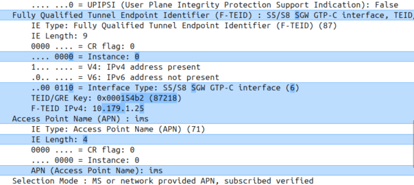
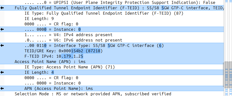
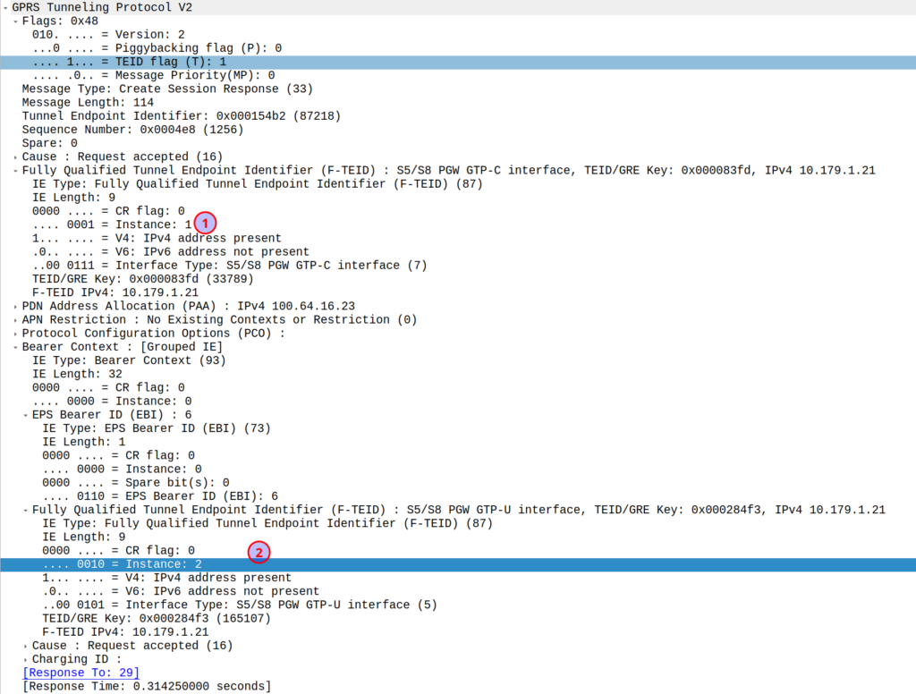
I was diffing two PCAPs the other day trying to work out what’s up, and noticed the Instance ID on a GTPv2 IE was different between the working and failing examples.
If more than one grouped information elements of the same type, but for a different purpose are sent with a message,
these IEs shall have different Instance values.
So if we’ve got two IEs of the same IE type (As we often do; F-TEIDs with IE Type 87 may have multiple instances in the same message each with different F-TEID interface types), then we differentiate between them by Instance ID.
The only exception to this rule is where we’ve got the same data, so if you’ve got one IE with the exact same values and purpose that exists twice inside the message.
This is part of a series of posts looking into SS7 and Sigtran networks. We cover some basic theory and then get into the weeds with GNS3 based labs where we will build real SS7/Sigtran based networks and use them to carry traffic.
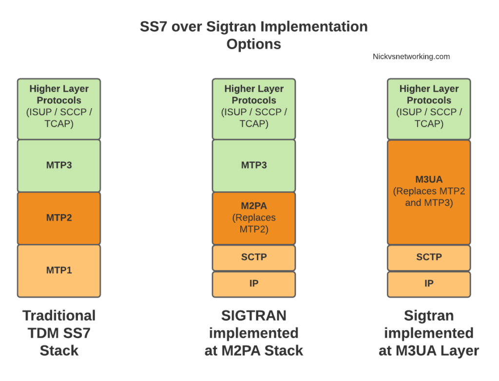
In our last post we talked about moving MTP2 onto IP and the options available.
When we split the SS7 stack onto IP we don’t need to do this at the Data Link Layer, we can instead do it higher up the stack. This is where we introduce M3UA.
MTP Level 3 User Adaptation Layer – M3UA replaces MTP3 with an IP based equivilent.
This is different to how we’d handle it with M2UA or M2PA where MTP3 remained unchanged, when you deploy M3UA links, there is no MTP3 anymore – it’s replaced with an IP based protocol transported via SCTP designed to do the same role as MTP3 but over IP – That protocol is M3UA.
This means the roles handled in MTP3 such as managing which available point codes are reachable over which linksets, failover, load sharing and reporting are all now handled by the M3UA protocol, because we loose the ability to just rely on MTP3 to do those things like we did when using lower layer protocols like M2PA or MTP2.
So what do you need to know to use M3UA?
Well, the first concept we need to wrap our head around is that we no longer have linksets or pointcode routes (We do, but they’re different) but instead have Application Servers, Application Server Processes and Routing Contexts.
If you’re following along at home and you want to hook your M3UA compatible AS into the Cisco ITP STP, I’ll be including the commands as we go along. The first step on the Cisco (assuming you’ve already defined the basic SS7 config) is to create a local M3UA instance:
cs7 m3ua 2905
 local-ip 10.179.2.154
With that out of the way, let’s cover ASPs & ASs (hehe – Ass).
You can think of the Application Server Process (ASP) as the client end of the “link set” of our virtual SS7 stack, it handles getting the SCTP association up, what IPs, ports and SCTP parameters are needed, and listens and communicates based on that, here’s an example on the Cisco ITP:
cs7 asp NickLab_ASP 2905 2905 m3ua
 remote-ip 10.0.1.252
 remote-ip 172.30.1.12
The ASP connects to a Signaling Gateway (In practical terms this is an STP).
That’s simple enough and now we can do our SCTP handshake, but nothing is going to get routed without introducing the Application Server (AS) itself, which is where we configure the routing and link to 1 or more ASPs and how we want to share traffic among them.
Point codes are still used in M3UA for sending traffic from an M3UA AS but it’s not what controls the routing to an AS.
That probably sounds confusing, I send traffic based on point code, but the traffic does’t get to the M3UA AS via point code? What gives?
Well, first we’ve got to introduce the Routing Context in M3UA.
Routing Contexts define what destinations are served by this AS. As an example, on our STP we’ll define a Routing Context inside the ITP inside the AS section, in this example we’re creating Routing Key 1 which will handle traffic to the point code 5.123.2, but we could equally define a routing-key for a given Global Title address too.
cs7 instance 0 as NickPC m3ua
 routing-key 1 5.123.2
 asp NickLab_ASP
 traffic-mode broadcast
Notice we didn’t define Routing Key X -> Point Code Y -> ASP Z ? That’s because we may have one or more ASPs associated with this (remember ASPs are kinda like Linksets).
For example the Point Code for an HLR might have multiple ASPs behind it, with traffic-mode loadshare to load balance the requests among all the HLRs.
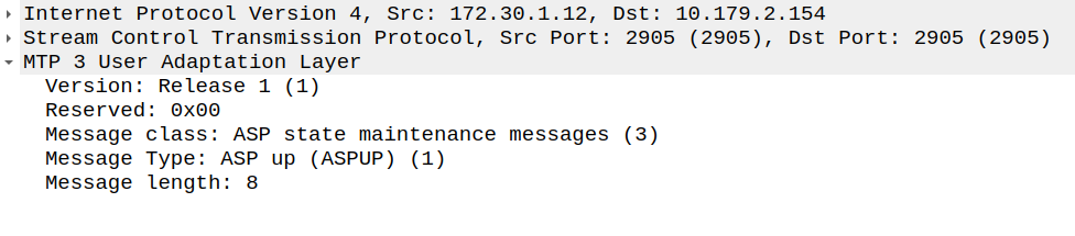
So what does it look like to bring this up? Let’s take a look at a link coming up.
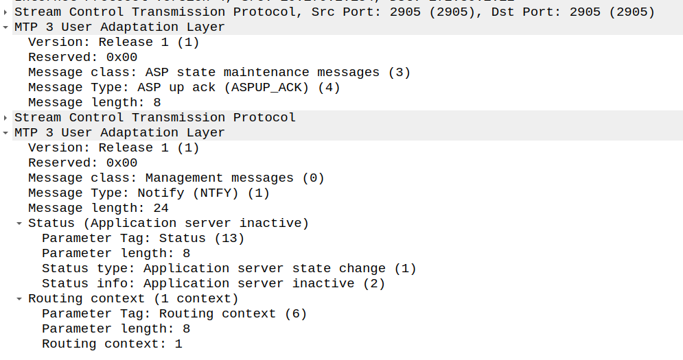
Now our ASP has told the Signaling Gateway it’s there, so our Signaling Gateway returns an ASPUP_ACK to confirm it’s got the message and the current AS state is inactive.
ASP Up Ack Message from SG (STP) to ASP
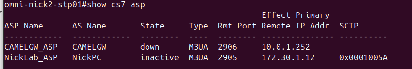
And with that our ASP is in “an up state, “inactive” state; it’s connected to the STP, but without any ASes associated with our ASP, it’s akin to having link layer but nothing else.
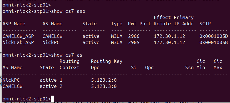
State in the STP showing an ASP without an active AS
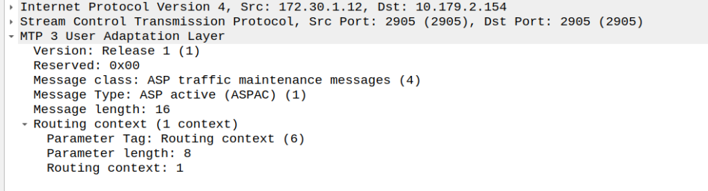
So next our ASP will send an ASPAC (ASP Active) message for the given routing contexts the AS serves, in this case, Routing Context 1.
ASP Active Message from ASP to SG (STP)
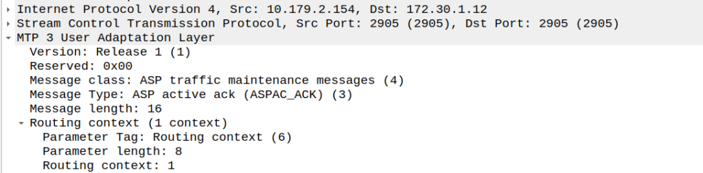
And with that, the Signaling Gateway (STP) send back an an ASPAC_ACK (ASP Active Ack) to confirm it’s got it, and the state changes.
ASP Active Ack Message from SG (STP) to ASP
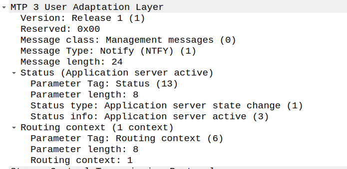
Because of how MTP3 worked advertising available point codes, the SG (STP) needs to tell the AS/ASP how it sees the world and the state of the connection.
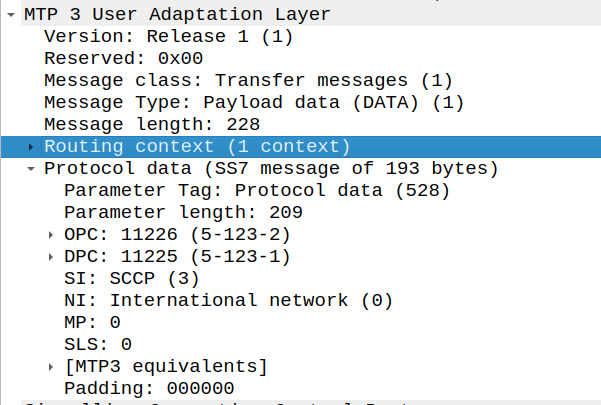
This is done with a NTFY (Notify) message from the STP/SG to indicate the state has changed to active, and what destinations are reachable, and at this point, we’re good to start handling traffic for that Routing Context.
And with that, we can start handling M3UA traffic.
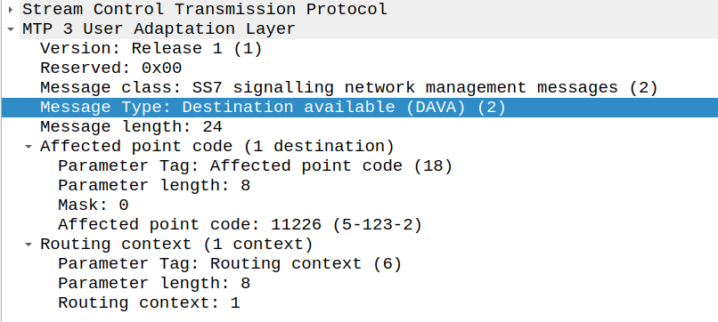
There’s only one more key dialog to wrap your heads around that’s the DAVA and DUNA messages.
DAVA is Destination Available, and DUNA is Destination Unavailable. The SG (STP) will send these messages to ASP/AS every time the reachability of a neighboring point code changes.
That’s the basics covered, I’m in the process of developing an HLR (Running with MAP/TCAP/SCCP/M3UA) extension for PyHSS, which in the future will allow us to experiment with more M3UA endpoints.
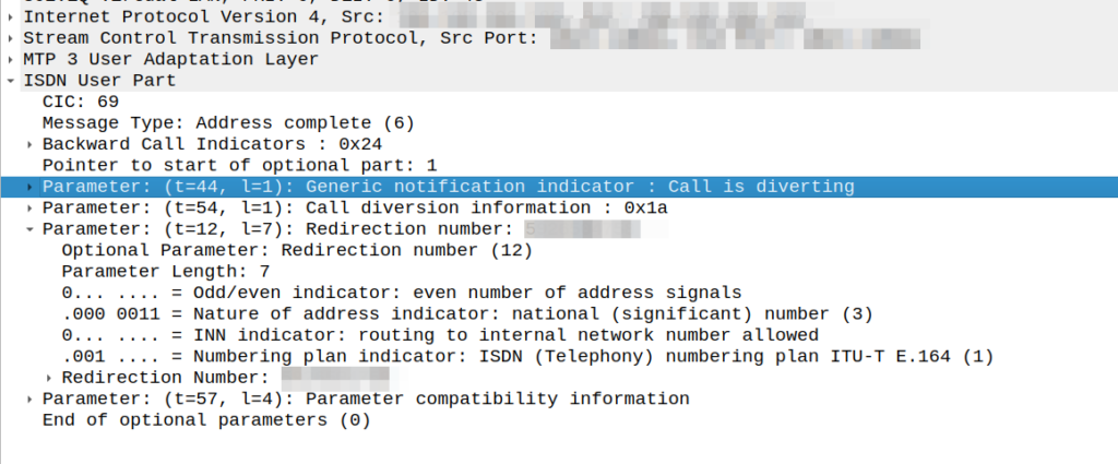
Had an interesting fault come across my desk the other day; calls were failing when the called party (an SSP we talk to via SS7/ISUP) had an exchange based call forward in place.
We’re a SIP based network, but we do talk some SS7/ISUP on the edges, and it was important that we handled this correctly.
I could see in the Address Complete Message (ACM) sent back to our network that there was redirection information here:
We would see the B party SSP release the call as soon as it sent this.
This made me wonder if we, as the originating network, were supposed to redirect to the new B party and send a new Initial Address Message?
After a lot of digging in the ITU Q.7xx docs (I’m not where near as fast at finding information in specs written prior to my birth, than I am with the 3GPP specs) I found my answer – These headers are informational only, the B party SSP is meant to re-target the message, and send us an Alerting or Answer message when it’s done so.
CAMEL is primarily focused on charging for Voice & SMS services, as data generally uses Diameter, so it’s voice and SMS we’ll focus on.
CAMEL is spoken between the MSC (gsmSSF) and the OCS (gsmSCF).
Basic Call State Model
CAMEL is closely related to the Intelligent Network stuff on the 1980s, and steals a lot of it’s ideas from there, unfortunately if you’re to read the CAMEL standard it also implies you were involved in IN stuff and had been born at that point, alas I was neither.
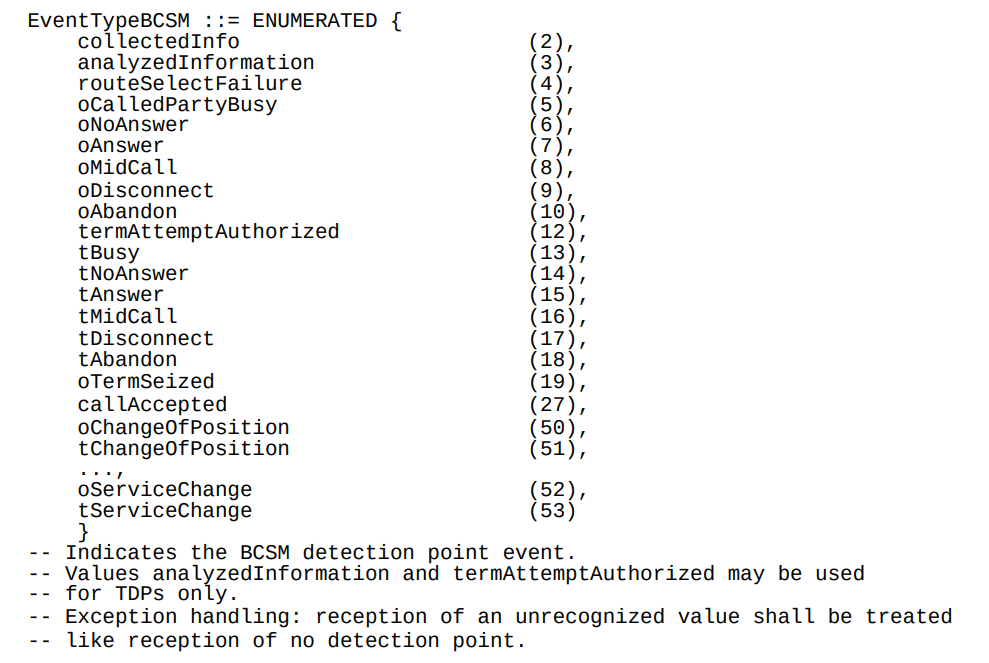
So the key to understanding CAMEL is the Basic Call State Model (BCSM) which is a model of all the different states a call can be in, such as ringing, answered, abandoned, call failed, etc, etc.
Over CAMEL, our OCS can be told by the MSC when a certain event happens; the MSC can tell the OCS, that the call has changed state. For example a BCSM event might indicate the call has hung up, is ringing, cancelled, etc.
Below is the list of all the valid BCSM states:
List of BCSM states for events
Basic MO Call with CAMEL
Our subscriber makes an outbound call.
Based on the data the MSC has in it from the HLR, it knows that we should use CAMEL for this call, and it has the SCCP Address of the OCS (gsmSCF) it needs to send the CAMEL messages to.
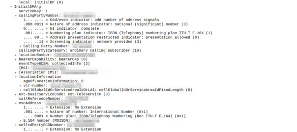
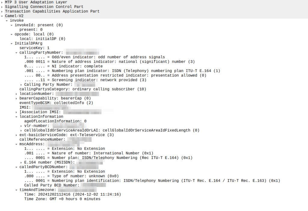
So the MSC sends an InitialDP message to the OCS (via it’s Global Title Address) to Authorize the call that the user is trying to make.
This is like any other Authorization step for an OCS, which allows the OCS to authorize the call by checking the subscriber is valid, check if they’re allowed to call that destination and they’ve got the balance to do so, etc.
initialDP message from an MSC to an OCS
The initialDP (Initial Detection Point) is telling our OCS all about the call event that’s being requested, who’s calling, what number they’ve dialed, where they are in the network (of note especially if they’re roaming), etc, etc.
Generally the OCS also uses this message as a chance to subscribe to BCSM Events using RequestReportBCSMEventArg so the OCS will get notified by the MSC when the state of the call changes. This means the MSC will tell us when the state of the call changes; events like the call getting answered, disconnected, etc. This is critical so we know when the call gets answered and hung-up, so we can charge correctly.
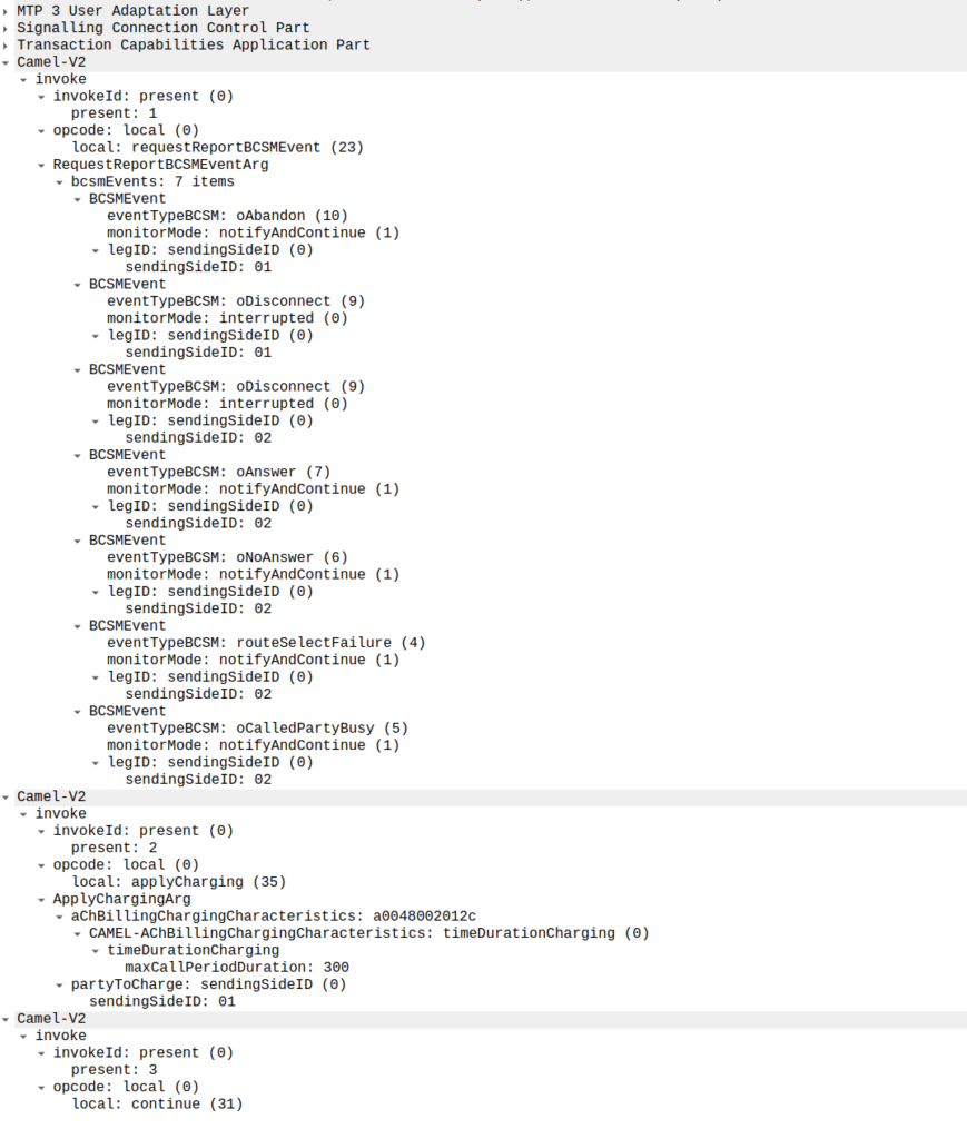
In the below example, as well as sending the Continue and RequestReportBCSMEventArg the OCS is also setting the ChargingArgs for this call, so the MSC knows who to charge (the caller) set via sendingSide and that the MSC must send an Apply Charging Report (ACR) messages every 300 units (1 unit = 100 ms, so a value of 300 = 300 x 100 milliseconds = 30 seconds) so the OCS keeps track of what’s going on.
continue sent by the OCS to the MSC, also including reportBCSMEvent and applyCharging messages
Or in a slightly less appropriate analogy but easier to understand for SIP folks, the InitialDP is sent for INVITE and the 180 RINGING is sent once the continue message is received.
Call is Answered
So at this stage our call can start to ring.
As we’ve subscribed to BCSM events in our last message, the MSC is going to tell us when the call gets answered or the call times out, is abandoned or the sun burns out.
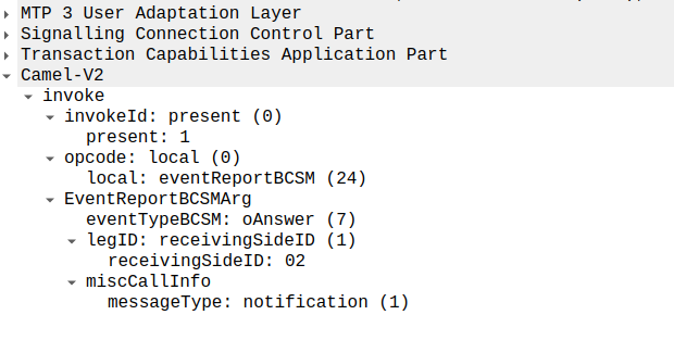
The MSC provides this info a eventReportBCSM, which is very simple and just tells us the event that’s been triggered, in the example below, the call was answered.
eventReportBCSM from MSC to OCS
These eventReportBCSM are informational from the MSC to the OCS, so the OCS doesn’t need to send anything back, but the OCS does need to mark the call as answered so it can start timing the call.
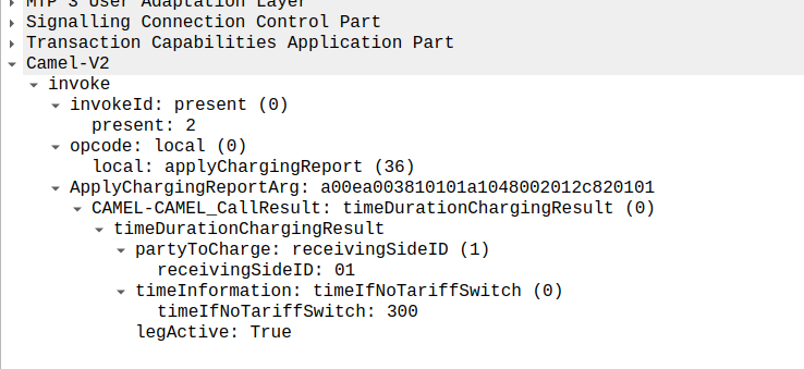
At this stage, the call is connected and our two parties are talking, but our MSC has been told it needs to send us applyChargingReports every 30 seconds (due to the value of 300 in maxCallPeriodDuration) after the call was connected, so the MSC sends the OCS it’s first applyChargingReport 30 seconds after the call was answered:
applyChargingReport sent by the MSC to the OCS every reporting period
We can calculate the duration of the call so far based on the time of the eventReportBCSM, then the OCS must make a decision of if it should allow the call to continue or not.
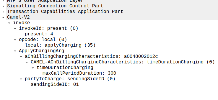
For simplicity’s sake, let’s imagine we’re still got a balance in the OCS and the OCS wants the call to continue, the OCS send back an applyCharging message to the MSC in response, and includes the current allowed maxCallPeriodDuration, keeping in mind the value is x100 and in nanoseconds (so this is 30 seconds).
applyCharging from the OCS back to the MSC
Perfect, our call is good to go for another 30 more seconds, son in 30 seconds we’ll get another ACR messages from MSC to the OCS to keep it abreast of what’s going on.
Now one of two things is going to happen, either subscriber is going to burn through all of their minutes, and get their call cutoff, or the call will end while they’ve still got balance, let’s look at both scenarios.
Normal Hangup Scenario
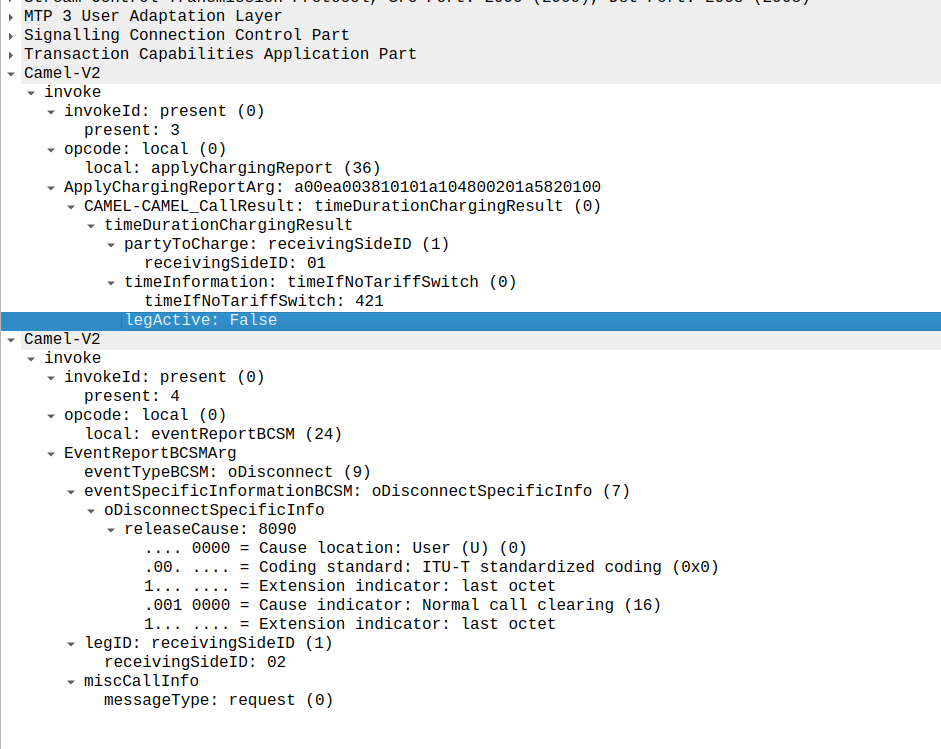
When the call ends, we get an applyChargingReport from the MSC to the OCS.
As we’ve subscribed to reportBCSMEvent we get both the applyChargingReport with legActive: False` so we know the call has hungup, and we’ve got an event report to tell us more about the event, in this case a hangup from the Originating Side.
reportBCSMEvent and applyChargingReport Sent by the MSC to the OCS to indicate the call has ended, note the legActive flag is now false
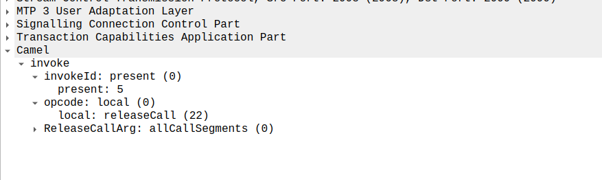
Lastly the OCS confirms by sending a releaseCall to the MSC, to indicate all legs should now terminate.
releaseCall Sent by OCS to MSC at the very end
So that’s it!
Obviously there are other flows, such as running out of balance mid-call, rejecting a call, SMS and PBX / VPN services that rely on CAMEL, but hopefully you now understand the basics of how CAMEL based charging looks and works.
If you’re looking for a CAMEL capable OCS or a CAMEL to Diameter or API gateway, get in touch!
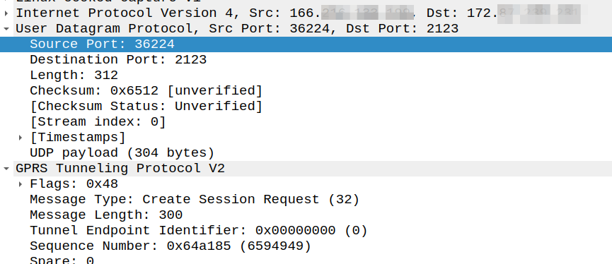
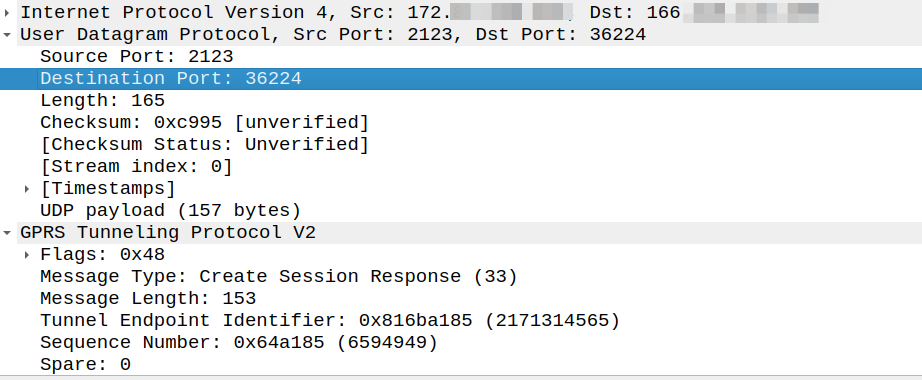
Ask anyone in the industry and they’ll tell you that GTPv2-C (aka GTP-C) uses port 2123, and they’re right, kinda.
Per TS 129.274 the Create Session Request should be sent to port 2123, but the source port can be any port:
The UDP Source Port for a GTPv2 Initial message is a locally allocated port number at the sending GTP entity.
So this means that while the Destination Port is 2123, the source port is not always 2123.
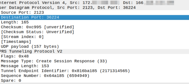
So what about a response to this? Our Create Session Response must go where?
Create Session request coming from 166.x.y.z from a random port 36225 Going to the PGW on 172.x.y.z port 2123
The response goes to the same port the request came on, so for the example above, as the source port was 36225, the Create Session Response must be sent to port 36225.
Because:
The UDP Destination Port value of a GTPv2 Triggered message and for a Triggered Reply message shall be the value of the UDP Source Port of the corresponding message to which this GTPv2 entity is replying, except in the case of the SGSN pool scenario.
But that’s where the association ends.
So if our PGW wants to send a Create Bearer Request to the SGW, that’s an initial message, so must go to port 2123, even if the Create Session Request came from a random different port.
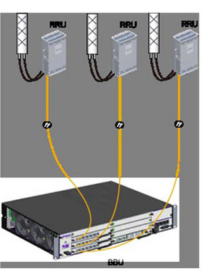
When Dickens wrote of Doctor Manette in the 1859, I doubt his intention was to write about the repeating history of RAN fronthaul standards – but I can’t really say for sure.
Setting the Scene
Our story starts with introducing CPRI (Common Public Radio Interface) interface, having been imprisoned in the Bastille of vendor lock in for the better part of twenty years.
Think of CPRI is less of a hard interoperable standard and more like how the Italian and French languages are both derived from Latin; it doesn’t mean that the two languages are the same, but they’ve got the same root and may share some common words and structures.
In practice this means that taking an Ericsson Radio and plugging it into a Huawei Baseband simply won’t work – With CPRI you must use the same vendor for the Baseband and the Radios.
“Nuts to this” the industry said after being stuck locked between the same radios and baseband for years; we should create a standard so we can mix and match between radio vendors, and even standardize some other stuff that’s been bothering us, so we’ll have a happy world of interoperability.
A world with interoperable fronthaul
With kit created that followed this standard, we’d be able to take components from vendor A, B & C, and fit them together like Lego, saving you some money along the way and giving you’ve got a working solution made of “best of breed” components, where everything is interoperable.
Omnitouch Lego base stations, which also fit together like Lego – Part of the Omnitouch Network Services “swag” from 2024
So the industry created a group to chart a path for a better tomorrow by standardizing these interfaces.
The group had many industry heavyweights like Nokia, NEC, LG, ZTE and Samsung joining.
The key benefits espoused on their website:
An open market will substantially reduce the development effort and costs that have been traditionally associated with creating new base station product ranges. The availability of off-the-shelf base station modules will enable manufacturers to focus their development efforts on creating further added value within the base station, encouraging greater innovation and more cost-effective products. Furthermore, as product development cycles will be reduced, new base station functions will become available on the market more quickly.
Mission statement of the group
In addition to being able to mix and match radios and basebands from different vendors, the group defined standards for centralized baseband, and interoperable standards, to allow a multi-vendor ecosystem to flourish.
And here’s the plot twist – The text above, was not written about OpenRAN, and it was not written about the benefits of eCPRI.
It was written about Open Base Station Architecture Initiative (OBSAI) and it was written 22 years ago.
*record screech sound*
Standards War you’ve never heard of: OBSAI vs CPRI
When OBSAI was defined it was not without competition; there was another competing fronthaul standard; that’s right, the mustache twirling lowlife from earlier in the story – CPRI.
Supported by Huawei, Nortel, NEC & Ericsson (among others), CPRI took a “gentle parenting” approach to the standards world, in contrast to OBSAI. Instead of telling all the vendors to agree on an interoperable front haul standard, CPRI just encouraged everyone to implement what their heart told them and what felt right to them.
As it happened, the industry favored the CPRI approach.
If a vendor wanted to add a new “word” in their CPRI “language” to add a new feature, they just went ahead and added it – It didn’t require anyone else to agree with them or changes to a common standard used by the industry, vendors could talk to the kit they made how they wanted.
CPRI has been the defacto non-standard used by all the big kit vendors for the past ~10 years.
The Death of OBSAI & the Birth of OpenRAN’s eCPRI
Why haven’t you heard of OBSAI? Why didn’t the OBSAI standard just serve as the basis for eCPRI – After all the last OBSAI release was less than 5 years before TIP started working on eCPRI publicly.
Is no more. It has ceased to be.
Did a schism over “uplink performance improvement” options lead to “irreconcilable differences” between parties leading to the breakup of the OBSAI group?
Nope.
Customers (MNOs) didn’t buy OBSAI based equipment in measurably larger quantities than CPRI kit. That’s it.
This meant the vendors invested less in paying teams to further develop the standards, the OBSAI group met less frequently, and in the end, member vendors didn’t bother adding support for OBSAI to new equipment and just used the easier and more flexible CPRI option instead.
At some point someone just stopped paying for the domain renewal and that was it, OBSAI was no more.
This is how the standards body ends, not with a bang, but with a whimper.
T.S. Elliot’s writings on the death of obsai
Those who do not learn from history…
The goals of the OBSAI Group and OpenRAN working groups are almost identical, so what lessons did Marconi, Motorola and Alcatel learn as members of OBSAI that other vendors could learn about OpenRAN strategy?
There are no mentions of OBSAI in any of the information published by OpenRAN advocates, and I’m wondering if folks aren’t aware that history tends to repeat and are ignorant to what came before it, or they’re just not learning lessons from the past?
So what can the OpenRAN industry learn from OBSAI?
Being a nerd, I started detailing the technical challenges, but that’s all window dressing; The biggest hurdle facing CPRI vs eCPRI are the same challenges OBSAI vs CPRI faced a decade prior:
To be relevant, OpenRAN kit has to be demonstrably better than what we have today AND provide a tangible cost saving.
OBSAI failed at achieving this, and so failed to meet it’s other more noble goals.
[At the time of writing this at least] I’d contend that neither of those two criteria have been met by OpenRAN.
What does the future hold for OpenRAN?
Looking into the crystal ball, will OpenRAN and eCPRI go the way of OBSAI, or will someone keep the OpenRAN dream alive?
Today, we’re still seeing the MNOs continue to provide tokenistic investment in OpenRAN. But being a cynic, I’d say the MNOs are feigning interest in OpenRAN products because it’s advantageous for them to do so.
The threat of OpenRAN has proven to be a great stick to beat the traditional vendors with to force them to lower their prices.
Think about the $14 billion USD Ericsson deal with AT&T, if chucking a few million at OpenRAN pilots / trials lead to AT&T getting even a 0.1% reduction in what they’re paying Ericsson, then the numbers would have worked out well in AT&Ts favor.
From the MNOs perspective, the cost to throw the odd pilot or trial to a hungry OpenRAN vendor to keep them on the hook is negligible, but the threat of OpenRAN provides leverage and bargaining power every time it’s contract renewal time with the big RAN vendors.
Already we’ve seen all the traditional RAN vendors move to neutralize this threat by introducing “OpenRAN compatible” equipment and talking up their commitment to openness.
This move by the RAN vendors takes this sting out of the OpenRAN threat, and means MNOs won’t have much reason to continue supporting OpenRAN.
This leaves the remaining OpenRAN vendors like Miss Havisham, forever waiting in their proverbial wedding dresses, having being left at the altar.
Okay, I’m mixing my Dickens’ references here, but it was too good not to.
Appendix
I’ve been enjoying writing more analysis than just technical content, let me know if this is something you’re interested in seeing more of.
I’ve been involved in two big OpenRAN integration projects, both of which went poorly and probably tainted my perspective. Enough time has passed to probably write up how it all went with the vendor names removed, but that’s a post for another time!
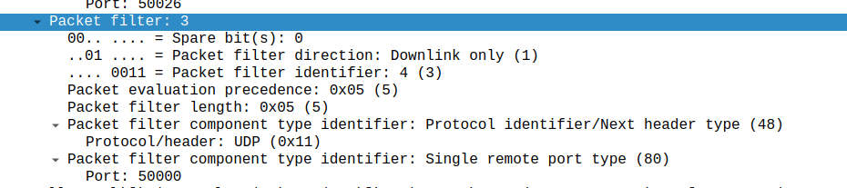
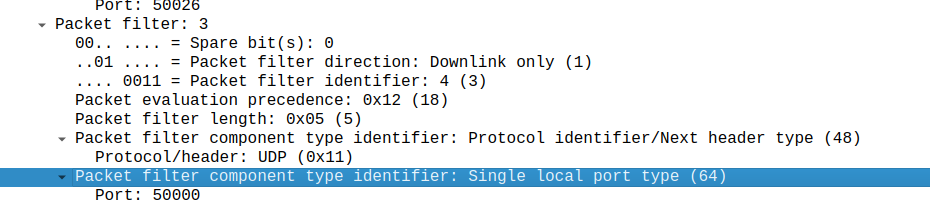
What is included in the Charging Rule on Gx ultimately turns into a Create Bearer Request on GTPv2-C.
But the mapping it’s always obvious, today I got stuck on the difference between a Single remote port type, and a single local port type, thinking that the Packet Filter Direction in the TFT controlled this – It doesn’t – It’s controlled by the order of your Traffic Flow Template rule.
Input TFT:
"permit out 17 from any 50000 to any"
Leads to Packet filter component type identifier: Single remote port type
Whereas a TFT of:
permit out 17 from any to any 50000
Leads to Packet filter component type identifier: Single local port type (64)
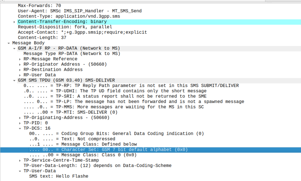
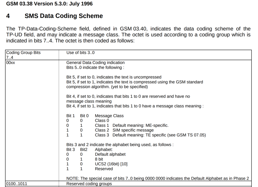
Stumbled across these the other day, while messing around with some values on our SMSc.
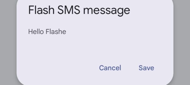
Setting the Data Coding Scheme to 16 with GSM7 encoding flags the SMS as “Flash message”, which means it pops up on the screen of the phone on top of whatever the user is doing.
While reading a quality telecom blog bam! There’s the flash SMS popping over whatever I was reading.
Oddly while there’s plenty of info online about Flash SMS, it does not appear in the 3GPP specifications for SMS.
Turns out they still work, move over RCS and A2P, it’s all about Flash messages!
There’s no real secret to this other than to set the Data Coding Scheme to 16, which is GSM7 with Flash class set. That’s it.
Obviously to take advantage of this you’d need to be a network operator, or have access to the network you wish to deliver to. Recently more A2P providers are filtering non vanilla SMS traffic to filter out stuff like SMS OTA message or SIM specific messages, so there’s a good chance this may not work through A2P providers.
I’ve been writing a fair bit recently about the “VoLTE Mess” – It’s something that’s been around for a long time, mostly impacting greenfield players rolling out LTE only, but now the big carriers are starting to feel it as they shut off their 2G and 3G networks, so I figured a brief history was in order to understand how we got here.
Note: I use the terms 4G or LTE interchangeably
The Introduction of LTE
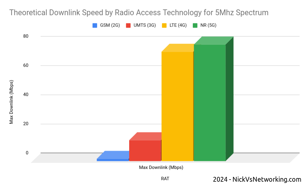
LTE (4G) is more “spectrally efficient” than the technologies that came before it. In simple terms, 1 “chunk” of spectrum will get you more speed (capacity) on LTE than the same size chunk of spectrum would on 2G or 3G.
So imagine it’s 2008 and you’re the CTO of a mobile network operator. Your network is congested thanks to carrying more data traffic than it was ever designed for (the first iPhone had launched the year before) and the network is struggling under the weight of all this new data traffic. You have two options here, to build more cell sites for more density (very expensive) or buy more spectrum (extremely expensive) – Both options see you going cap in hand to the finance team and asking for eye-wateringly large amounts of capital for either option.
But then the answer to your prayers arrives in the form of 3GPP’s Release 8 specification with the introduction of LTE. Now by taking some 2G or 3G spectrum, and by using it on 4G, you can get ~5x more capacity from the same spectrum. So just by changing spectrum you own from 2G or 3G to 4G, you’ve got 5x more capacity. Hallelujah!
So you go to Nortel and buy a packet core, and Alcatel and Siemens provide 4G RAN (eNodeBs) which you selectively deploy on the cell sites that are the most congested. The finance team and the board are happy and your marketing team runs amok with claims of 4G data speeds. You’ve dodged the crisis, phew.
This is the path that all established mobile operators took; throw LTE at the congested cell sites, to cheaply and easily free up capacity, and as the natural hardware replacement cycle kicked in, or cell sites reached capacity, swap out the hardware to kit that supports LTE in addition to the 2G and 3G tech.
Circuit Switched Fallback
But it’s hard to talk about the machinations of late 2000s telecom executives, without at least mentioning Hitler.
This video below from 15 years ago is pretty obscure and fairly technical, but the crux of it it is that Hitler is livid because LTE does not have a “CS Domain” aka circuit switched voice (the way 2G and 3G had handled voice calls).
It was optional to include support for voice calls in the LTE network (Voice over LTE) when you launched LTE services. So if you already had a 2G or 3G network (CS Network) you could just keep using 2G and 3G for your voice calls, while getting that sweet capacity relief.
So our hypothetical CTO, strapped for cash and data capacity, just didn’t bother to support VoLTE when they launched LTE – Doing so would have taken more time to launch, during which time the capacity problem would become worse, so “don’t worry about VoLTE for now” was the mantra.
All the operators who still had 2G and 3G networks, opted to just “Fallback” to using the 2G / 3G network for calling. This is called “Circuit Switched Fallback” aka CSFB.
Operators loved this as they got the capacity relief provided by shifting to 4G/LTE (more capacity in the network is always good) and could all rant about how their network was the fastest and had 4G first, this however was what could be described as a “Foot gun” – Something you can shoot yourself in the foot with in the future.
Operators eventually introduce VoLTE
Time ticked on an operators built out their 4G networks, and many in the past 10 years or so have launched VoLTE in their own networks.
For phones that support it, in areas with blanket 4G coverage, they can use VoLTE for all their calls.
But that’s the sticking point right there – If the phones support it.
But if the phones don’t support it, they’re roaming or making emergency calls, there is always been the safety blanket of 2G or 3G and Circuit Switched fallback to well, fall back to.
There’s no driver for operators who plan to (or are required to) operate a 2G or 3G network for the foreseeable future, to ensure a high level of VoLTE support in their devices.
For an operator today with 2G or 3G, Voice over LTE is still optional. Many operators still rely exclusively on Circuit Switched Fallback, and there are only a handful of countries that have turned off 2G and 3G and rely solely on VoLTE.
VoLTE Handset Support
For the past 16 years phone manufacturers have been making LTE capable phones.
But that does not mean they’ve been making phones that support Voice over LTE.
But it’s never been an issue up until this point, as there’s always been a circuit switched (2G/3G) network to fall back to, so the fact that these chips may not support VoLTE was not a big problem.
Many of the cheaper chipsets that power phones simply don’t support VoLTE – These chips do support LTE for data connections but rely on Circuit Switched Fallback for voice calls. This is in part due to the increased complexity, but also because some of the technologies for VoLTE (like AMR) required intellectual property deals to licence to use, so would add to the component cost to manufacture, and in the chips game, keeping down component cost is critical.
Even for chips that do support Voice over LTE, it’s “special”. Unlike calling in 2G or 3G that worked the same for every operator, phone manufacturers require a “Carrier Bundle” for each operator, containing that specific operators’ special flavor of VoLTE, that operator uses in their network.
This is because while VoLTE is standardized (Despite some claims to the contrary) a lot of “optional” bits have existed, and different operators built networks with subtle differences in the “flavor” of their Voice over LTE (IMS) stack they used. The OEMs (Phone / Chip manufacturers) had to handle these changes in the devices they made, for in order to sell their phones through that operator.
This means I can have a phone from vendor X that works with VoLTE on Network Y, but does not support VoLTE on Network Z.
Worse still, knowing which phones are supported is a bit of a guessing game.
Most operators sell phones directly to their customer base, so buying an Network Y branded phone from Vendor X, you know it’s going to support Network Y’s VoLTE settings, but if you change carriers, who knows if it’ll still support it?
When you’ve still got a Circuit Switched network it’s not the end of the world, you’ll just use CSFB and probably not realize it, until operators go to shut down 2G / 3G networks…
IMS Profile selection on an engineering mode MTK based Android handset
Navigating the Maze of VoLTE Compatibility
Here are some simple checklist you can ask your elderly family members if they ask if their phone is VoLTE compatible:
Does the underlying chipset the phone is based on support VoLTE? (you can find this out by disassembling the phone and checking the datasheets for the components from the OEMs after signing NDAs for each)
Does the underlying chipset require a “carrier bundle” of settings to have been loaded for this operator in order to support VoLTE (See Qualcomm MBM as an example)?
What version of this list am I currently on (generally set in the factory) and does it support this operator? (You can check by decapping the ICs and dumping their NVRAM and then running it through a decompiler)
Does my phones OS (Android / iOS) require a “carrier bundle” of it’s own to enable VoLTE? Is my operator in the version of the database on the phone? (See Android’s Carrier Database for example) (You can find the answer by rooting the phone and running some privileged commands to poke around the internal file system)
Does my operator / MNO support VoLTE – Does my plan / package support VoLTE? (You can easily find the answer by visiting the store and asking questions that don’t appear on the script)
If you managed to answer yes to all of the above, congratulations! You have conditional VoLTE support on your phone, although you probably don’t have a working phone anymore.
Wait, conditional VoLTE support?
That’s right folks, VoLTE will work in some scenarios with your operator!
If you plan on traveling, well your phone may support VoLTE at home, but does the phone have VoLTE roaming enabled? Many phones support VoLTE in the home network, but resort to CSFB when roaming.
If it does support VoLTE roaming, does the network you’re visiting support VoLTE roaming? Has the roaming agreement (IRA) between the operator you’re using while traveling and your home operator been updated to include VoLTE Roaming? These IRAs (AA.12 / AA.13 docs) also indicate if the network must turn off IPsec encryption for the VoLTE traffic when roaming, which is controlled by the phone anyway.
Phew, all this talk of VoLTE roaming while traveling scares me, I think I’ll stay home in the safety of the Australian bush with all these great friendly animals around a phone that supports VoLTE on my home network.
Ah – After spending some time in the Australian bush one of our many deadly animals bit me. Time to call for help! Wait, what about emergency calls over VoLTE? Again, many phones support VoLTE for normal calls, fall back to 2G or 3G for the emergency call, so if you have one of those phones (You’ll only find out if you try to make an emergency call and it fails) and try to make an emergency call in a country without 2G or 3G, you’d better find a payphone.
Sarcasm aside, there’s no dataset or compatibility matrix here – No simple way to see if your phone will work for VoLTE on a given operator, even if the underlying chip does support VoLTE.
Operators in Australia which recently shut down their 3G network, were mandated to block devices that didn’t support VoLTE for emergency calling. They did this using an Equipment Identity Register, and blocking devices based on the Type Allocation Code, but this scattergun approach just blocked non-carrier issued devices, regardless of it they supported VoLTE or VoLTE emergency calling.
Blame Game
So who’s to blame here?
There’s no one group to blame here, the industry has created a shitty cycle here:
Standards orgs for having too many “flavors” available
Operators deploying their own “Flavors” of VoLTE then mandating OEMs / Chip manufacturers comply with their “flavor”.
OEMs / Chip manufactures respond by adding “Carrier Bundles” to account for this per-operator customization
I’ve got some ideas on a way to unscramble this egg, and it’s going to take a push from the industry.
If you’re in the industry and keen to push for a fix, get in touch!
It’s time to get a long term solution to this problem, and we as an industry need to lead the change.
Oh boy this has been a pain in the backside with IMS / VoLTE devices using TCP and how they handle the underlying TCP sockets.
A mobile phone from manufacturer A, wants every SIP dialog to be in it’s own TCP session, while a phone from manufacturer B wants a unique TCP session per transaction, while manufacturer C thinks that every SIP message should reuse the same transaction.
So an MT call to manufacturer A, who wants every SIP dialog in it’s own transaction would look something like this:
PCSCF:44738 -> UE:5060; TCP SYN UE:5060 -> PCSCF:44738; TCP SYN/ACK PCSCF:44738 -> UE:5060; TCP ACK --- TCP connection is now open to UE from P-CSCF--- --- Start of new SIP Transaction 1 & Dialog --- PCSCF:44738 -> UE:5060; TCP PSH - SIP INVITE.... UE:5060 -> PCSCF:44738; TCP ACK
--- Start of SIP Transaction 2 --- PCSCF:44738 -> UE:5060; TCP PSH - SIP BYE.... UE:5060 -> PCSCF:44738; TCP ACK, PSH - SIP 200.... --- End of SIP Transaction 2 & SIP Dialog --- PCSCF:44738 -> UE:5060; TCP FIN UE:5060 -> PCSCF:44738; TCP ACK --- End of TCP Connection ---
Where UE:5060 – is the IP & port of the UE, as advertised in the Contact: header, while PCSCF:44738 is the PCSCF IP and a random TCP port used for this connection.
But for manufacturer B, who wants a unique TCP session per transaction, they want it to look like this:
PCSCF:44738 -> UE:5060; TCP SYN UE:5060 -> PCSCF:44738; TCP SYN/ACK PCSCF:44738 -> UE:5060; TCP ACK --- TCP connection is now open to UE from P-CSCF--- --- Start of new SIP Transaction 1 & Dialog --- PCSCF:44738 -> UE:5060; TCP PSH - SIP INVITE.... UE:5060 -> PCSCF:44738; TCP ACK
--- Start of TCP Session 2 ---- PCSCF:32627 -> UE:5060; TCP SYN UE:5060 -> PCSCF:32627; TCP SYN/ACK PCSCF:32627 -> UE:5060; TCP ACK --- Start of SIP Transaction 2 --- PCSCF:32627 -> UE:5060; TCP PSH - SIP BYE.... UE:5060 -> PCSCF:32627; TCP ACK, PSH - SIP 200.... --- End of SIP Transaction 2 & SIP Dialog --- PCSCF:32627 -> UE:5060; TCP FIN UE:5060 -> PCSCF:32627; TCP ACK --- End of TCP Connection 2 ---
And then manufacturer C wants just the one TCP session to be used for everything, so they open the TCP connection when they register, and that’s all we use for everything.
Is there any logic to this? Nope, seems to be tied to the underlying chipset (Qualcomm vs Mediatek vs Unisoc) and the SIP stack used (Qualcomm, MTK, Unisoc, Samsung, Apple).
We’ve profiled devices into one of 3 behaviors, and then we tag them based on user agent as to what “persona” they demand from the network.
I can’t believe I’m still talking about VoLTE / IMS handset support and it’s almost 2025…. For context IMS was “standardized” 17 years ago.
This is the next post in my series on SS7, and today we’re taking a look at SCCP the Signalling Connection Control Part (SCCP).
High Level
Global Title uses the routing features from SCCP, which is another layer on top of MTP3.
SCCP allows us to route on more than just point code, instead we can route based on two new fields, Subsystem Number and Global Title.
Subsystem Number is the type of system we are looking to reach, ie an HLR, MSC, CAMEL Gateway, etc.
The Global Title generally looks like an E.164 formatted phone number, and often it is just that.
Somewhere along the chain (typically at the end of it) an STP somewhere needs to perform Global Title Translation to analyse the SCCP header (Subsystem Number, Point Code & Global Title) and finally turn that into a single point code to route the MTP3 message to.
The advantage of this is we are no longer just limited to routing messages based on Point Code.
This is how the international SS7 Network used for roaming is structured and addressed – All using Global Title rather than Point Codes.
The need for SCCP
For starters, after all this talk of MTP3 and Point Codes, why the need to add SCCP?
Let’s go back in time and look at the motivators…
1. Address space is finite
Point codes are great, and when we’ve spoken about them before, I’ve compared them to IPv4 address, but rather than ranging from 0.0.0.0 to 255.255.255.255 (32 bits on IPv4) international signaling point codes range from 0.0.0 to 7.255.7 (14 bits).
The problem with IPv4’s 32 bit addresses is they run out. The problem with the ITU International Signaling Point Codes is that they too, are a limited resource with only 16,383 possible ISPCs.
~700 operators worldwide each with ~100 network elements would be 70k point codes to address them all – That’s not going to fit into our 16k possible Point Codes.
Global Title fixes this, because we’re able to use E.164 phone number ranges (which are plentiful) for addressing, we’re still not at IPv6 levels of address space, but pretty hefty.
2. Service Discovery by Subsystem
Now imagine you’re a VLR looking to find an HLR. The VLR and the HLR are both connected to an STP, but how does the VLR know where to reach the HLR?
One option would be to statically set every route for the Point Code of every HLR into every possible VLR and visa-versa, but that gets messy fast.
What if the VLR could just send a request to the STP and indicate that the request needs to be routed to any HLR, and the STP takes care of finding a SS7 node capable of handling the request, much a Diameter Routing Agent routes based on Application ID.
SCCP’s “Subsystem Number” routing can handle this as we can route based on SSN.
3. Service Discovery by MSISDN
Having an SMS destined to a given MSISDN requires the SMSc to know where to route it.
Likewise an MSC wanting to call a given number.
There’s a lot of MSISDN ranges. Like a lot. Like every phone mobile number.
Having every a table on every SSP/SCP in the network know where every MSISDN range is in the world and what point code to go through to reach it is not practical.
Instead, being able to have the SCP/SSPs (like our MSC or SMSc) send all off-net traffic to an STP frees us the individual SCP/SSPs from this role; they just forward it to their connected STP.
Our STP can analyse the destination MSISDN and make these routing decisions for us, using Global Title Translation based on rules in the Global Title Table on the STP.
For example by adding each of the domestic / national MSISDN ranges/prefixes into the Global Title Table on the STP (along with the corresponding point code to route each one to), the STP can look at the destination MSISDN in the message and forward to the STP for the correct operator.
Likewise a route can match anything where the Global Title address is outside of the local country and send it to an international signaling provider.
Global title takes care of this as we can route based on a phone number.
4. Tokenistic Security
By “Hiding” network elements behind Global Titles, you don’t expose as much information about your internal network, and the only way people can “find” your network elements would be scanning through all the possible addresses in your (publicly advertised) Global Title range (wardialing is back baby!).
But the phrases “Security” and “SS7” don’t really belong together…
The SCCP Header
The SCCP header has a Called Party and a Calling Party, and this is where the magic happens.
These can be made up for any number of 3 parts:
Global Title Address
Subsystem Number
Point Code
We can route on any combination of these.
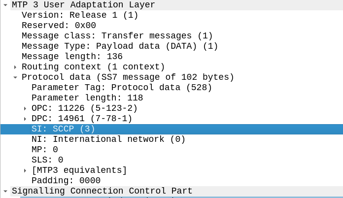
To indicate we’re using SCCP, we set the Signaling Indicator bit in the M3UA / MTP3 message to SCCP:
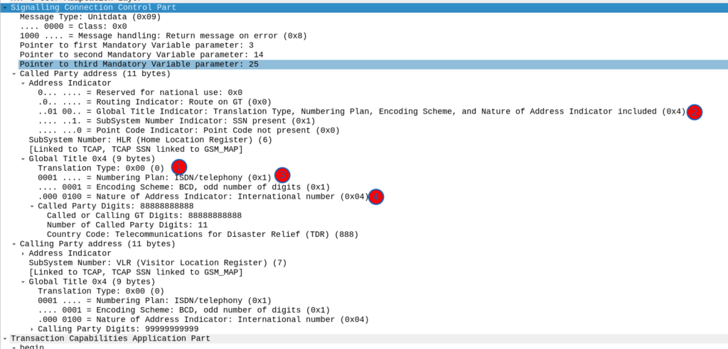
Great, now we can look at our SCCP header.
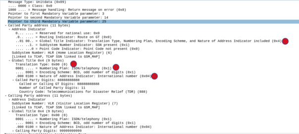
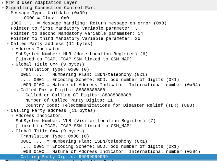
It looks like there’s a lot going on, but we can see the calling and called party (888888888 is called by 9999999999) with the Subsystem number set (888888888 is called for subsystem HLR, from 999999999 which is a VLR).
The closest TCP/IP analogy I can think of here is that of port numbers, there’s still an IP (Point code) but the port number allows us to specify multiple applications that run at a higher layer. This analogy falls down when we consider that the Point Code is generally set to that of your STP, not the final STP.
For this to work, we’ve got to have at least one Signaling Transfer Point in the flow, where we send the request to.
Somewhere (generally at the end of the chain of STPs), an STP is going to perform Global Title Translation.
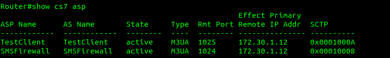
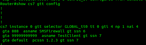
What does this look like? Well let’s have a look at my GT table for the example above, in my lab network, I’ve got two nodes attached (via M3UA but could equally be on MTP3 links), my test MAP client where I’m originating this traffic, and an SMS Firewall, I can see they’re both up here:
Now knowing this I need to setup my SCCP routing for Global Title. In the screenshot above, the Called Party was 888888888 with Subsystem Number 7. Inside the SCCP request, there’s a few other fields, the Translation Type we have set to 0, Global Title Indicator is 4 (route on Global Title), while Numbering Plan Indicator is 1 (ISDN) and Nature of Address Indicator is 4 (International).
So on my Cisco ITP I define a GTT Selector to target traffic with these values, Translation Type is 0, Global Title Indicator is 4, Number Plan is 1 and the Nature of Address Indicator is 4.
So we’d define a Global Title Translation selector like the one below to match this traffic:
But that’s only matching the group of traffic, it’s not going to match based on the actual SCCP Called Party. So now I need to define a translation for each Global Title address (Called /Calling party) or prefix I want to route, I’ve setup anything starting with 888 to route to the `SMSFirewall` ASP endpoint.
I could stop here and my request addressed to 888888888 would make it to the SMSFirewall ASP, but the response never would, like in all SS7 routing, we need to define the return route translation too, which is what I’ve done for 999999 to route to the TestClient.
Lastly I’ve added a wildcard route, this means if this STP doesn’t know how to resolve a GT address matching the rules in the top line, it’ll forward the request to the STP at point code 1.2.3 – This is how you’d do your connection to an IPX / Signaling exchange.
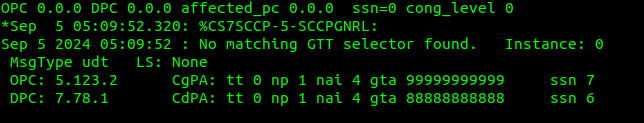
Debugging this can be a massive pain in the backside, but if you enable logging you can see when GT rules are not matched, like in the example below.
If your network is quiet enough, it’s sometimes easier to just make your rules based on what you observe failing to route.
So with those routes in place, when we send a request with the Global Title called party starting with 8888888 it’s routed to M3UA ASP SMSFirewall, which handles the request, and then sends the response back to the MAPClient M3UA ASP.
The Data Coding Scheme (DCS or TP-DCS) header in an SMS body indicates what encoding is used in that message.
It means if we’re using UCS-2 (UTF16) special characters like Emojis etc, in in our message, the phone knows to decode the data in the message body using UTF, because the Data Coding Scheme (DCS) header indicates the contents are encoded in UTF.
Likewise, if we’re not using any fancy characters in our message and the message is encoded as plain old GSM7, we set set the DCS to 0 to indicate this is using GSM7.
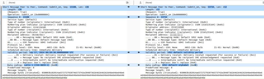
From my experience, I’d always assumed that DCS0 (Default) == GSM7, but today I learned, that’s not always the case. Some SMSc entities treat DCS0 as Latin.
Let me explain why this is stupid and why I wasted a lot of time on this.
We can indicate that a message is encoded as Latin by setting the DCS to 0x03:
We cannot indicate that the message is encoded as GSM7 through anything other than the default alphabet (DCS 0).
Latin has it’s own encoding flag, if I wanted the message treated as Latin, I’d indicate the message encoding is Latin in the DCS bit!
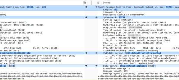
I spent a bunch of time trying to work out why a customer was having issues getting messages to subscribers on another operator, and it turned out the other operator treats messages we send to them on SMPP with DCS0 as Latin encoding, and then cracks the sads when trying to deliver it.
The above diff shows the message we send (Right), and the message they dry to deliver (left).