One of the guys at work asked a seemingly simple question, is the PLMN with MCC 505 and MNC 57 the same as MCC 505 MNC 057 – It’s on 6 octets after all.
So is Mobile Network Code 57 the same as Mobile Network Code 057 in the PLMN code?
The answer is no, and it’s a massive pain in the butt.
All countries use 3 digit Mobile Country Codes, so Australia, is 505. That part is easy.
The tricky part is that some countries (Like Australia) use 2 digit Mobile Network Codes, while others (Like the US) use 3 digit mobile network codes.
Why would you do this? Why would a regulator opt to have 1/10th the addressable size of network codes – I don’t know, and I haven’t been able to find an answer – If you know please drop a comment, I’d love to know.
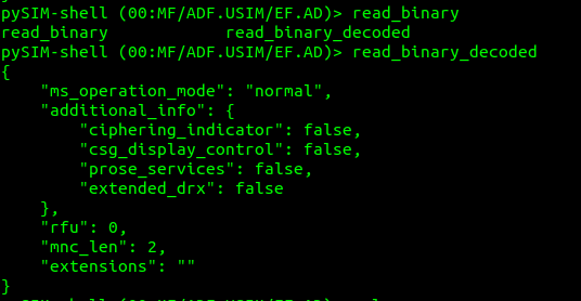
That’s all well and good from a SIM perspective, but less useful for scenarios where you might be the Visited PLMN for example, and only see the IMSI of a Subscriber.
We worked on a project in a country that mixed both 2 digit and 3 digit Mobile Network Codes, under the same Mobile Country Code. Certain Qualcomm phones would do very very strange things, and it took us a long time and a lot of SIM OTA to resolve the issue, but that’s a story for another day…
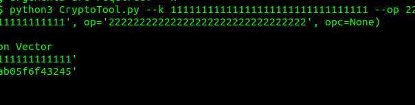
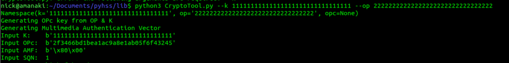
Namespace(k='11111111111111111111111111111111', op='22222222222222222222222222222222', opc=None) Generating OPc key from OP & K Generating Multimedia Authentication Vector Input K: b'11111111111111111111111111111111' Input OPc: b'2f3466bd1bea1ac9a8e1ab05f6f43245' Input AMF: b'\x80\x00'
Of course, being open source, you can grab the functions out of this and make a little script to convert everything in a CSV or whatever format your key data is in.
So what about OPc to OP? Well, this is a one-way transaction, we can’t get the OP Key from an OPc & Ki.
If you’re working with the larger SIM vendors, there’s a good chance they key material they send you won’t actually contain the raw Ki values for each card – If it fell into the wrong hands you’d be in big trouble.
Instead, what is more likely is that the SIM vendor shares the Ki generated when mixed with a transport key – So what you receive is not the plaintext version of the Ki data, but rather a ciphered version of it.
But as long as you and the SIM vendor have agreed on the ciphering to use, an the secret to protect it with beforehand, you can read the data as needed.
This is a tricky topic to broach, as transport key implementation, is not covered by the 3GPP, instead it’s a quasi-standard, that is commonly used by SIM vendors and HSS vendors alike – the A4 / K4 Transport Encryption Algorithm.
It’s made up of a few components:
K2 is our plaintext key data (Ki or OP)
K4 is the secret key used to cipher the Ki value.
K7 is the algorithm used (Usually AES128 or AES256).
It’s important when defining your electrical profile and the reuqired parameters, to make sure the operator, HSS vendor and SIM vendor are all on the same page regarding if transport keys will be used, what the cipher used will be, and the keys for each batch of SIMs.
Here’s an example from a Huawei HSS with SIMs from G&D:
We’re using AES128, and any SIMs produced by G&D for this batch will use that transport key (transport key ID 1 in the HSS), so when adding new SIMs we’ll need to specify what transport key to use.
The first thing people learn about SIMs or the Smart Cards that the SIM / USIM app runs on, is that “There’s a little computer in the card”. So how little is this computer, and what’s the computing power in my draw full of SIMs?
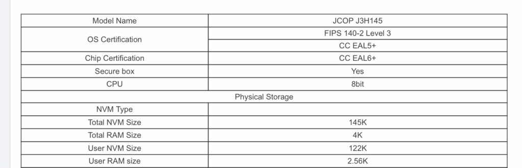
So for starters the SIM manufacturers love their NDAs, so I can’t post the chip specifications for the actual cards in my draw, but here’s some comparable specs from a seller selling Java based smart cards online:
Specs for Smart Card
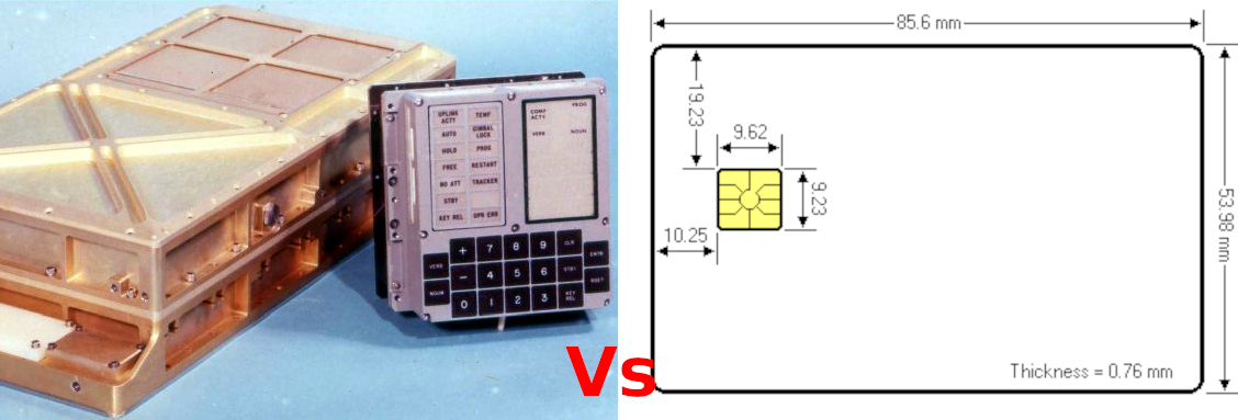
4K of RAM is 4069 bytes. For comparison the Apollo Guidance Computer had 2048 words of RAM, but each “word” was 16 bits (two bytes), so actually this would translate to 4069 bytes so equal with one of these smart cards in terms of RAM – So the smart card above is on par with the AGC that took humans to the moon in terms of RAM, althhough the SIMs would be a wee bit larger if they were also using magnetic core memory like the AGC!
The Nintendo Entertainment System was powered by a MOS Technology 6502, it had access to 2K of RAM, two the Smart Card has twice as much RAM as the NES, so it could get you to the moon and play Super Mario Bros.
What about comparing Non-Volatile Memory (Storage)? Well, the smart card has 145KB of ROM / NVM, while Apollo flew with 36,864 words of RAM, each word is two bits to 73,728 Bytes, so roughly half of what the Smart Card has – Winner – Smart Card, again, without relying on core rope memory like AGC.
SIM cards are clocked kinda funkily so comparing processor speeds is tricky. Smart Cards are clocked off the device they connect to, which feeds them a clock signal via the CLK pin. The minimum clock speed is 1Mhz while the max is 5Mhz.
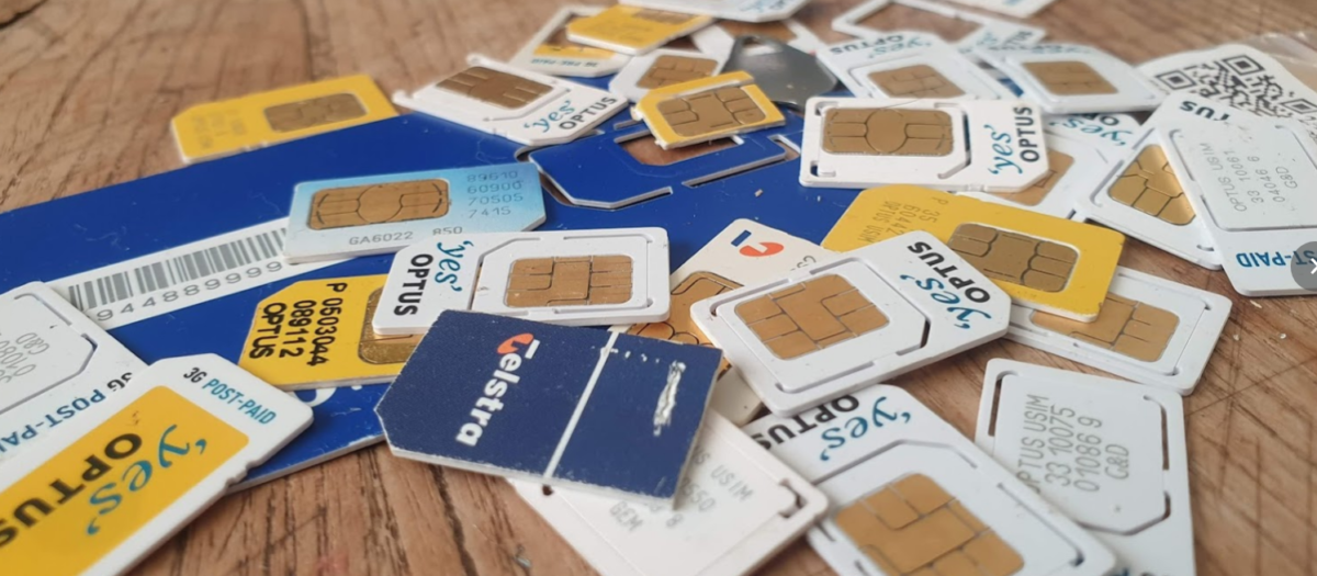
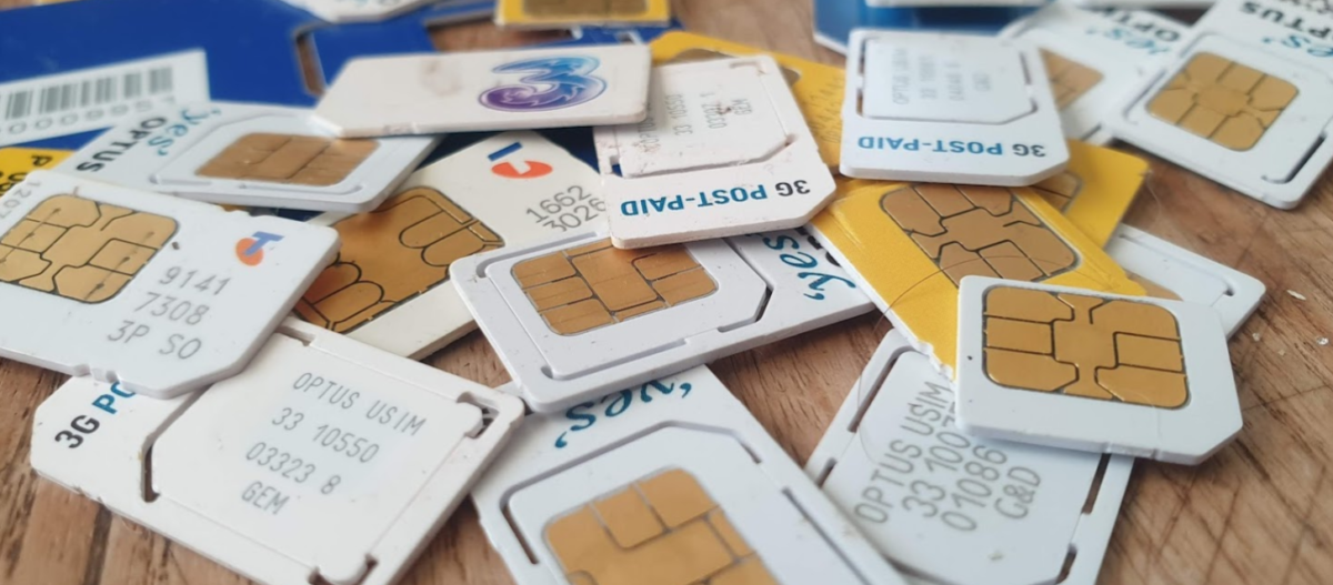
Now I’m somewhat of a hoarder when it comes to SIM Cards; in the course of my work I have to deal with a lot of SIMs…
Generally when we’re getting SIMs manufactured, during the Batch Approval Process (BAP) the SIM vendor will send ~25 cards for validation and testing. It’s not uncommon to go through several revisions. I probably do 10 of these a year for customers, so that’s 250 cards right there.
Then when the BAP is done I’ll get another 100 or so production cards for the lab, device testing, etc, this probably happens 3 times a year.
So that’s 550 SIMs a year, I do clean out every so often, but let’s call it 1000 cards in the lab in total.
In terms of ROM that gives me a combined 141.25 MB, I could store two Nintendo 64 games, or one Mini CD of data, stored across a thousand SIM cards – And you thought installing software from a few floppies was a pain in the backside, imagine accessing data from 1000 Smart Cards!
What about tying the smart cards together to use as a giant RAM BUS? Well our 1000 cards give us a combined 3.91 MB of RAM, well that’d almost be enough to run Windows 95, and enough to comfortably run Windows 3.1.
Practical do do any of this? Not at all, now if you’ll excuse me I think it’s time I throw out some SIMs…
I never cease to be amazed as to what I can do with Wireshark.
While we’re working with Smart Card readers and SIM cards, capturing and Decoding USB traffic to see what APDUs are actually being sent can be super useful, so in this post we’ll look at how we can use Wireshark to sniff the USB traffic to view APDUs being sent to smart cards from other software.
For the purposes of this post I’ll be reading the SIM cards with pySim, but in reality it’ll work with any proprietary SIM software, allowing you to see what’s actually being said to the card by your computer.
If you want to see what’s being sent between your phone and SIM card, the Osmocom SIMtrace is the device for you (And yes it also uses Wireshark for viewing this data!).
Ok, that’s all the prerequisites sorted, next we need to find the bus and device ID of our smart card reader,
We can get this listed with
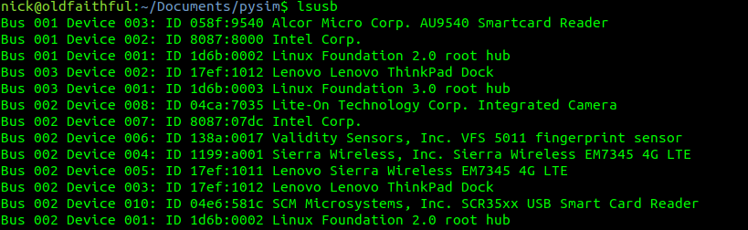
lsusb
Here you can see I have a Smart Card reader on Bus 1 device 03 and another on Bus 2 device 10.
The reader I want to use is the “SCM Microsystems, Inc. SCR35xx USB Smart Card Reader” so I’ll jott down Bus 2 device 10. Yours will obviously be different, but you get the idea.
Finding the USB traffic in Wireshark
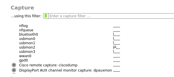
Next we’ll fire up Wireshark, if you’ve got your permissions right and followed along, you should see a few more interfaces starting with usbmonX in the capture list.
Because the device I want to capture from is on Bus 2, we’ll select usbmon2 and start capturing,
As you can see we’ve got a bit of a firehose of data, and we only care about device 10 on bus 2, so let’s filter for that.
So let’s generate some data and then filter for it, to generate some data I’m going to run pySim-read to read the data on a smart card that’s connected to my PC, and then filter to only see traffic on that USB device,
In my case as the USB device is 10 it’s got two sub addresses, so I’ll filter for USB Bus 2, device 10 sub-address 1 and 2, so the filter I’ll use is:
usb.addr=="2.10.1" or usb.addr=="2.10.2"
But this doesn’t really show us much, so let’s tell Wireshark this is PCSC/UCCID data to decode it as such;
So we’ll select some of this traffic -> Decode as -> USBCCID
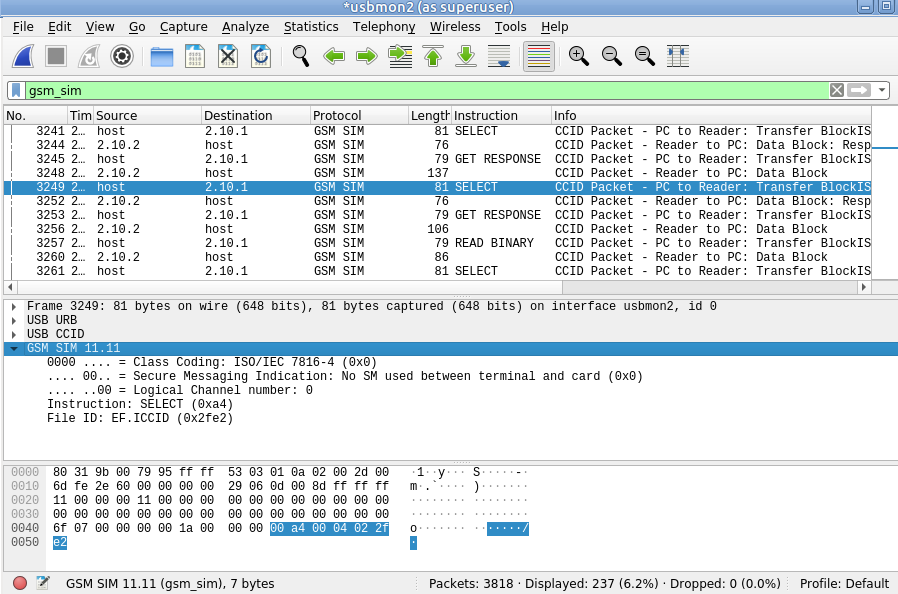
Still not seeing straight APDUs, so let’s tell Wireshark one more bit of information – That we want to decode this information as GSM SIM data;
Again, we’ll select the data part of the USBCCID traffic -> Decode As -> GSM_SIM
And bingo, just like that we can now filter by gsm_sim and see the APDUs being sent / received.
This is part 3 of an n part tutorial series on working with SIM cards.
So in our last post we took a whirlwind tour of what an APDU does, is, and contains.
Interacting with a card involves sending the APDU data to the card as hex, which luckily isn’t as complicated as it seems.
While reading what the hex should look like on the screen is all well and good, actually interacting with cards is the name of the game, so that’s what we’ll be doing today, and we’ll start to abstract some of the complexity away.
Getting Started
To follow along you will need:
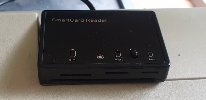
A Smart Card reader – SIM card / Smart Card readers are baked into some laptops, some of those multi-card readers that read flash/SD/CF cards, or if you don’t have either of these, they can be found online very cheaply ($2-3 USD).
A SIM card – No need to worry about ADM keys or anything fancy, one of those old SIM cards you kept in the draw because you didn’t know what to do with them is fine, or the SIM in our phone if you can find the pokey pin thing. We won’t go breaking anything, promise.
You may end up fiddling around with the plastic adapters to change the SIM form factor between regular smart card, SIM card (standard), micro and nano.
USB SIM / Smart Card reader supports all the standard form factors makes life a lot easier!
To keep it simple, we’re not going to concern ourselves too much with the physical layer side of things for interfacing with the card, so we’ll start with sending raw APDUs to the cards, and then we’ll use some handy libraries to make life easier.
PCSC Interface
To abstract away some complexity we’re going to use the industry-standard PCSC (PC – Smart Card) interface to communicate with our SIM card. Throughout this series we’ll be using a few Python libraries to interface with the Smart Cards, but under the hood all will be using PCSC to communicate.
pyscard
I’m going to use Python3 to interface with these cards, but keep in mind you can find similar smart card libraries in most common programming languages.
At this stage as we’re just interfacing with Smart Cards, our library won’t have anything SIM-specific (yet).
We’ll use pyscard to interface with the PCSC interface. pyscard supports Windows and Linux and you can install it using PIP with:
pip install pyscard
So let’s get started by getting pyscard to list the readers we have available on our system:
#!/usr/bin/env python3
from smartcard.System import *
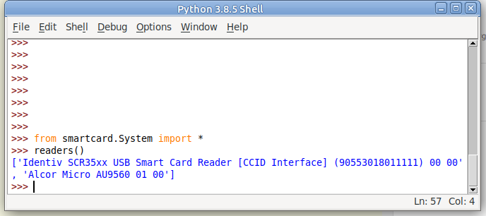
print(readers())
Running this will output a list of the readers on the system:
Here we can see the two readers that are present on my system (To add some confusion I have two readers connected – One built in Smart Card reader and one USB SIM reader):
(If your device doesn’t show up in this list, double check it’s PCSC compatible, and you can see it in your OS.)
So we can see when we run readers() we’re returned a list of readers on the system.
I want to use my USB SIM reader (The one identified by Identiv SCR35xx USB Smart Card Reader CCID Interface 00 00), so the next step will be to start a connection with this reader, which is the first in the list.
So to make life a bit easier we’ll store the list of smart card readers and access the one we want from the list;
#!/usr/bin/env python3
from smartcard.System import *
r = readers()
connection = r[0].createConnection()
connection.connect()
So now we have an object for interfacing with our smart card reader, let’s try sending an APDU to it.
Actually Doing something Useful
Today we’ll select the EF that contains the ICCID of the card, and then we will read that file’s binary contents.
This means we’ll need to create two APDUs, one to SELECT the file, and the other to READ BINARY to get the file’s contents.
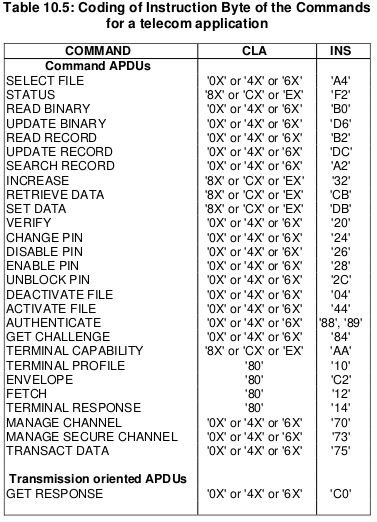
We’ll set the instruction byte to A4 to SELECT, and B0 to READ BINARY.
Table of Instruction bytes from TS 102 221
APDU to select EF ICCID
The APDU we’ll send will SELECT (using the INS byte value of A4 as per the above table) the file that contains the ICCID.
Each file on a smart card has been pre-created and in the case of SIM cards at least, is defined in a specification.
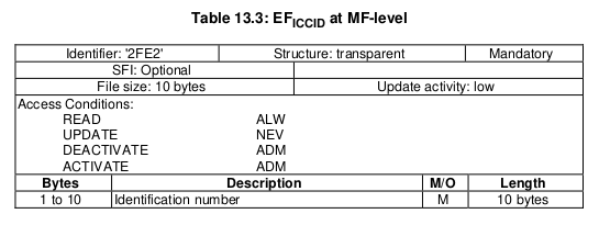
For this post we’ll be selecting the EF ICCID, which is defined in TS 102 221.
Information about EF-ICCID from TS 102 221
To select it we will need it’s identifier aka File ID (FID), for us the FID of the ICCID EF is 2FE2, so we’ll SELECT file 2FE2.
Parameter 1 – Selection Control (Limit search options)
00 (Select by File ID)
P2
Parameter 1 – More selection options
04 (No data returned)
Lc
Length of Data
02 (2 bytes of data to come)
Data
File ID of the file to Select
2FE2 (File ID of ICCID EF)
So that’s our APDU encoded, it’s final value will be A0 A4 00 04 02 2FE2
So let’s send that to the card, building on our code from before:
#!/usr/bin/env python3
from smartcard.System import *
from smartcard.util import *
r = readers()
connection = r[0].createConnection()
connection.connect()

print("Selecting ICCID File")
data, sw1, sw2 = connection.transmit(toBytes('00a40004022fe2'))
print("Returned data: " + str(data))
print("Returned Status Word 1: " + str(sw1))
print("Returned Status Word 2: " + str(sw2))
If we run this let’s have a look at the output we get,
We got back:
Selecting ICCID File
 Returned data: []
 Returned Status Word 1: 97
 Returned Status Word 2: 33
So what does this all mean?
Well for starters no data has been returned, and we’ve got two status words returned, with a value of 97 and 33.
We can lookup what these status words mean, but there’s a bit of a catch, the values we’re seeing are the integer format, and typically we work in Hex, so let’s change the code to render these values as Hex:
#!/usr/bin/env python3
from smartcard.System import *
from smartcard.util import *
r = readers()
connection = r[0].createConnection()
connection.connect()

print("Selecting ICCID File")
data, sw1, sw2 = connection.transmit(toBytes('00a40004022fe2'))
print("Returned data: " + str(data))
print("Returned Status Word 1: " + str(hex(sw1)))
print("Returned Status Word 2: " + str(hex(sw2)))
Now we’ll get this as the output:
Selecting ICCID File Returned data: [] Returned Status Word 1: 0x61 Returned Status Word 2: 0x1e
Status Word 2 contains a value of 1e which tells us that there are 30 bytes of extra data available with additional info about the file. (We’ll cover this in a later post).
So now we’ve successfully selected the ICCID file.
Keeping in mind with smart cards we have to select a file before we can read it, so now let’s read the binary contents of the file we selected;
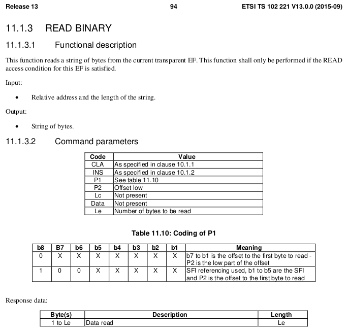
The READ BINARY command is used to read the binary contents of a selected file, and as we’ve already selected the file 2FE2 that contains our ICCID, if we run it, it should return our ICCID.
If we consult the table of values for the INS (Instruction) byte we can see that the READ BINARY instruction byte value is B0, and so let’s refer to the spec to find out how we should format a READ BINARY instruction:
Code
Meaning
Value
CLA
Class bytes – Coding options
A0 (ISO 7816-4 coding)
INS
Instruction (Command) to be called
B0 (READ BINARY)
P1
Parameter 1 – Coding / Offset
00 (No Offset)
P2
Parameter 2 – Offset Low
00
Le
How many bytes to read
0A (10 bytes of data to come)
We know the ICCID file is 10 bytes from the specification, so the length of the data to return will be 0A (10 bytes).
Let’s add this new APDU into our code and print the output:
#!/usr/bin/env python3
from smartcard.System import *
from smartcard.util import *
r = readers()
connection = r[0].createConnection()
connection.connect()

print("Selecting ICCID File")
data, sw1, sw2 = connection.transmit(toBytes('00a40000022fe2'))
print("Returned data: " + str(data))
print("Returned Status Word 1: " + str(hex(sw1)))
print("Returned Status Word 2: " + str(hex(sw2)))
And we have read the ICCID of the card.
Phew.
That’s the hardest thing we’ll need to do over.
From now on we’ll be building the concepts we covered here to build other APDUs to get our cards to do useful things. Now you’ve got the basics of how to structure an APDU down, the rest is just changing values here and there to get what you want.
In our next post we’ll read a few more files, write some files and delve a bit deeper into exactly what it is we are doing.
In our last post we covered the file system structure of a smart card and the basic concepts of communication with cards. In this post we’ll look at what happens on the application layer, and how to interact with a card.
For these examples I’ll be using SIM cards, because admit it, you’ve already got a pile sitting in a draw, and this is a telco blog after all. You won’t need the ADM keys for the cards, we’ll modify files we’ve got write access to by default.
Commands & Instructions
So to do anything useful with the card we need issue commands / instructions to the card, to tell it to do things. Instructions like select this file, read it’s contents, update the contents to something else, verify my PIN, authenticate to the network, etc.
The term Command and Instruction are used somewhat interchangeably in the spec, I realise that I’ve done the same here to make it just as confusing, but instruction means the name of the specific command to be called, and command typically means the APDU as a whole.
The “Generic Commands” section of 3GPP TS 31.101 specifies the common commands, so let’s take a look at one.
The creatively named SELECT command/instruction is used to select the file we want to work with. In the SELECT command we’ll include some parameters, like where to find the file, so some parameters are passed with the SELECT Instruction to limit the file selection to a specific area, etc, the length of the file identifier to come, and the identifier of the file.
The card responds with a Status Word, returned by the card, to indicate if it was successful. For example if we selected a file that existed and we had permission to select, we’d get back a status word indicating the card had successfully selected the file. Status Words are 2 byte responses that indicate if the instruction was successful, but also the card has data it wants to send to the terminal as a result of the instruction, how much data the terminal should expect.
So if we just run a SELECT command, telling the card to select a file, we’ll get back a successful response from the card with a data length. Next need to get that data from the card. As the card can’t initiate communication, the GET RESPONSE instruction is sent to the card to get the data from the card, along with the length of the data to be returned.
The GET RESPONSE instruction/command is answered by the card with an APDU containing the data the card has to send, and the last 2 bytes contain the Status Word indicating if it was successful or not.
APDUs
So having covered the physical and link layers, we now move onto the Application Layer – where the magic happens.
Smart card communications is strictly master-slave based when it comes to the application layer.
The terminal sends a command to the card, which in turn sends back a response. Command -> Response, Command -> Response, over and over.
These commands are contained inside APplication Data Units (APDUs).
So let’s break down a simple APDU as it appears on the wire, so to speak.
The first byte of our command APDU is taken up with a header called the class byte, abbreviated to CLA. This specifies class coding, secure messaging options and channel options.
In the next byte we specify the Instruction for the command, that’s the task / operation we want the card to perform, in the spec this is abbreviated to INS.
The next two bytes, called P1 & P2 (Parameter 1 & Parameter 2) specify the parameters of how the instruction is to be to be used.
Next comes Lc – Length of Command, which specifies the length of the command data to follow,
Datacomes next, this is instruction data of the length specified in Lc.
Finally an optional Le – Length of expected response can be added to specify how long the response from the card should be.
Crafting APDUs
So let’s encode our own APDU to send to a card, for this example we’ll create the APDU to tell the card to select the Master File (MF) – akin to moving to the root directory on a *nix OS.
For this we’ll want a copy of ETSI TS 102 221 – the catchily named “Smart cards; UICC-Terminal interface; Physical and logical characteristics” which will guide in the specifics of how to format the command, because all the commands are encoded in hexadecimal format.
So here’s the coding for a SELECT command from section 11.1.1.1 “SELECT“,
For the CLA byte in our example we’ll indicate in our header that we’re using ISO 7816-4 encoding, with nothing fancy, which is denoted by the byte A0.
For the next but we’ve got INS (Instruction) which needs to be set to the hex value for SELECT, which is represented by the hex value A4, so our second byte will have that as it’s value.
The next byte is P1, which specifies “Selection Control”, the table in the specification outlines all the possible options, but we’ll use 00 as our value, meaning we’ll “Select DF, EF or MF by file id”.
The next byte P2 specifies more selection options, we’ll use “First or only occurrence” which is represented by 00.
The Lc byte defines the length of the data (file id) we’re going to give in the subsequent bytes, we’ve got a two byte File ID so we’ll specify 2 (represented by 02).
Finally we have the Data field, where we specify the file ID we want to select, for the example we’ll select the Master File (MF) which has the file ID ‘3F00‘, so that’s the hex value we’ll use.
So let’s break this down;
Code
Meaning
Value
CLA
Class bytes – Coding options
A0 (ISO 7816-4 coding)
INS
Instruction (Command) to be called
A4 (SELECT)
P1
Parameter 1 – Selection Control (Limit search options)
00 (Select by File ID)
P2
Parameter 1 – More selection options
00 (First occurrence)
Lc
Length of Data
02 (2 bytes of data to come)
Data
File ID of the file to Select
3F00 (File ID of master file)
So that’s our APDU encoded, it’s final value will be A0 A4 00 00 02 3F00
So there we have it, a valid APDU to select the Master File.
In the next post we’ll put all this theory into practice and start interacting with a real life SIM cards using PySIM, and take a look at the APDUs with Wireshark.
The pins on the terminal / card reader are arranged so that when inserting a card, the ground contact is the first contact made with the reader, this clever design consideration to protect the card and the reader from ESD damage.
Operating Voltages
When Smart Cards were selected for use in GSM for authenticating subscribers, all smart cards operated at 5v. However as mobile phones got smaller, the operating voltage range became more limited, the amount of space inside the handset became a premium and power efficiency became imperative. The 5v supply for the SIM became a difficult voltage to provide (needing to be buck-boosted) so lower 3v operation of the cards became a requirement, these cards are referred to as “Class B” cards. This has since been pushed even further to 1.8v for “Class C” cards.
If you found a SIM from 1990 it’s not going to operate in a 1.8v phone, but it’s not going to damage the phone or the card.
The same luckily goes in reverse, a card designed for 1.8v put into a phone from 1990 will work just fine at 5v.
This is thanks to the class flag in the ATR response, which we’ll cover later on.
Clocks
As we’re sharing one I/O pin for TX and RX, clocking is important for synchronising the card and the reader. But when smart cards were initially designed the clock pin on the card also served as the clock for the micro controller it contained, as stable oscillators weren’t available in such a tiny form factor. Modern cards implement their own clock, but the clock pin is still required for synchronising the communication.
I/O Pin
The I/O pin is used for TX & RX between the terminal/phone/card reader and the Smart Card / SIM card. Having only one pin means the communications is half duplex – with the Terminal then the card taking it in turns to transmit.
Reset Pin
Resets the card’s communications with the terminal.
Filesystem
So a single smart card can run multiple applications, the “SIM” is just an application, as is USIM, ISIM and any other applications on the card.
These applications are arranged on a quasi-filesystem, with 3 types of files which can be created, read updated or deleted. (If authorised by the card.)
Because the file system is very basic, and somewhat handled like a block of contiguous storage, you often can’t expand a file – when it is created the required number of bytes are allocated to it, and no more can be added, and if you add file A, B and C, and delete file B, the space of file B won’t be available to be used until file C is deleted.
This is why if you cast your mind back to when contacts were stored on your phone’s SIM card, you could only have a finite number of contacts – because that space on the card had been allocated for contacts, and additional space can no longer be allocated for extra contacts.
So let’s take a look at our 3 file types:
MF (Master File)
The MF is like the root directory in Linux, under it contains all the files on the card.
DF (Dedciated File)
An dedicated file (DF) is essentially a folder – they’re sometimes (incorrectly) referred to as Directory Files (which would be a better name).
They contain one or more Elementary Files (see below), and can contain other DFs as well.
Dedicated Files make organising the file system cleaner and easier. DFs group all the relevant EFs together. 3GPP defines a dedicated file for Phonebook entries (DFphonebook), MBMS functions (DFtv) and 5G functions (DF5gs).
We also have ADFs – Application Dedicated Files, for specific applications, for example ADFusim contains all the EFs and DFs for USIM functionality, while ADFgsm contains all the GSM SIM functionality.
The actual difference with an ADF is that it’s not sitting below the MF, but for the level of depth we’re going into it doesn’t matter.
DFs have a name – an Application Identifier (AID) used to address them, meaning we can select them by name.
EF (Elementary File)
Elementary files are what would actually be considered a file in Linux systems.
Like in a Linux file systems EFs can have permissions, some EFs can be read by anyone, others have access control restrictions in place to limit who & what can access the contents of an EF.
There are multiple types of Elementary Files; Linear, Cyclic, Purse, Transparent and SIM files, each with their own treatment by the OS and terminal.
Most of the EFs we’ll deal with will be Transparent, meaning they ##
ATR – Answer to Reset
So before we can go about working with all our files we’ll need a mechanism so the card, and the terminal, can exchange capabilities.
There’s an old saying that the best thing about standards is that there’s so many to choose, from and yes, we’ve got multiple variants/implementations of the smart card standard, and so the card and the terminal need to agree on a standard to use before we can do anything.
This is handled in a process called Answer to Reset (ATR).
When the card is powered up, it sends it’s first suggestion for a standard to communicate over, if the terminal doesn’t want to support that, it just sends a pulse down the reset line, the card resets and comes back with a new offer.
If the card offers a standard to communicate over that the terminal does like, and does support, the terminal will send the first command to the card via the I/O line, this tells the card the protocol preferences of the terminal, and the card responds with it’s protocol preferences. After that communications can start.
Basic Principles of Smart Cards Communications
So with a single I/O line to the card, it kind of goes without saying the communications with the card is half-duplex – The card and the terminal can’t both communicate at the same time.
Instead a master-slave relationship is setup, where the smart card is sent a command and sends back a response. Command messages have a clear ending so the card knows when it can send it’s response and away we go.
Like most protocols, smart card communications is layered.
At layer 1, we have the physical layer, defining the operating voltages, encoding, etc. This is standardised in ISO/IEC 7816-3.
Above that comes our layer 2 – our Link Layer. This is also specified in ISO/IEC 7816-3, and typically operates in one of two modes – T0 or T1, with the difference between the two being one is byte-oriented the other block-oriented. For telco applications T0 is typically used.
Our top layer (layer 7) is the application layer. We’ll cover the details of this in the next post, but it carries application data units to and from the card in the form of commands from the terminal, and responses from the card.
Coming up Next…
In the next post we’ll look into application layer communications with cards, the commands and the responses.
I know a little bit about SIM cards / USIM cards / ISIM Cards. Enough to know I don’t know very much about them at all.
So throughout this series of posts of unknown length, I’ll try and learn more and share what I’m learning, citing references as much as possible.
So where to begin? I guess at the start,
A supposedly brief history of Smart Cards
There are two main industries that have driven the development and evolution of smart cards – telecom & banking / finance, both initially focused on the idea that carrying cash around is unseemly.
This planet has – or rather had – a problem, which was this: most of the people living on it were unhappy for pretty much of the time. Many solutions were suggested for this problem, but most of these were largely concerned with the movement of small green pieces of paper, which was odd because on the whole it wasn’t the small green pieces of paper that were unhappy.
Douglas Adams – The Hitchhiker’s Guide to the Galaxy
When the idea of Credit / Debit Cards were first introduced the tech was not electronic, embossed letters on the card were fed through that clicky-clacky-transfer machine (Google tells me this was actually called the “credit card imprinter”) and the card details imprinted onto carbon copy paper.
Customers wanted something faster, so banks delivered magnetic strip cards, where the card data could be read even more quickly, but as the security conscious of you will be aware, storing data on magnetic strips on a card to be read by any reader, allows them to be read by any reader, and therefore duplicated really easily, something the banks quickly realised.
To combat this, card readers typically would have a way to communicate back to a central bank computer. The central computer verified the PIN entered by the customer was correct, confirmed that the customer had enough money in their balance for the transaction and it wasn’t too suspicious. This was, as you would imagine in the late 1980’s early 1990’s, rather difficult to achieve. A reliable (and cheap) connection back to a central bank computer wasn’t always a given, nor instant, and so this was still very much open to misuse.
“Carders” emmerged, buying/selling/capturing credit card details, and after programming a blank card with someone else’s fraudulently obtained card details, could write them on a blank card before going on a spending spree for a brief period of time. Racking up a giant debt that wasn’t reconciled against the central computer until later, when the card was thrown away and replaced with another.
I know what you’re thinking – I come to this blog for ramblings about Telecommunications, not the history of the banking sector. So let’s get onto telco;
The telecom sector faced similar issues, at the time mobile phones were in their infancy, and so Payphones were how people made calls when out and about.
A phone call from a payphone in Australia has sat at about $0.40 for a long time, not a huge amount, but enough you’d always want to be carrying some change if you wanted to make calls. Again, an inconvenience for customers as coins are clunky, and an inconvenience for operators as collecting the coins from tens of thousands of payphones is expensive.
Telcos around the world trailed solutions, including cards with magnetic strips containing the balance of the card, but again people quickly realised that you could record the contents of the magnetic stripe data of the card when it had a full balance, use all the balance on the card, and then write back the data you stored earlier with a full balance.
So two industries each facing the same issue: it’s hard to securely process payments offline in a way that can’t be abused.
Enter the smart card – a tiny computer in a card that the terminal (Payphone or Credit Card Reader) interacts with, but the card is very much in charge.
When used in a payphone, the caller inserts the smart card and dials the number, and dialog goes something like this (We’ll assume Meter Pulses are 40c worth):
Payphone: “Hey SmartCard, how much credit do you have on you?”
Smart Card: “I have $1.60 balance”
*Payphone ensures card has enough credit for the first meter pulse, and begins listening for Meter Pulses*
*When a meter pulse received:*
Payphone: “Please deduct $0.40 from your Balance”
Smart Card: “Ok, you have $1.20 remaining”
This process repeats for each meter pulse (Payphone metering is a discussion for another day) until all the credit has been used / Balance is less than 1 meter pulse charge.
While anyone could ask the smart card “Hey SmartCard, how much credit do you have on you?” it would only return the balance, and if you told the smart card “I used $1 credit, please deduct it” like the payphone did, you’d just take a dollar off the credit stored on the card.
Saying “Hey SmartCard set the balance to $1,000,000” would result in a raised eyebrow from the SmartCard who rejects the request.
After all – It’s a smart card. It has the capability to do that.
So in the telecom sector single use smart cards were rolled out, programmed in the factory with a set dollar value of credit, sold at that dollar value and thrown away when depleted.
The banking industry saw even more potential, balance could be stored on the card, and the PIN could be verified by the card, the user needs to know the correct PIN, as does the smart card, but the terminal doesn’t need to know this, nor does it need to talk back to a central bank computer all the time, just every so often so the user gets the bill.
It worked much the same way, although before allowing a deduction to be made from the balance of the card, a user would have to enter their PIN which was verified by the card before allowing the transaction.
Eventually these worlds collided (sort of), both wanting much the same thing from smart cards. So the physical characteristics, interface specs (rough ones) and basic communications protocol was agreed on, and what eventually became ISO/IEC 7816 was settled upon.
Any card could be read by any terminal, and it was up to the systems implementer (banks and telecos initially) what data the card did and what the terminal did.
Active RFID entered the scene and there wasn’t even a need for a physical connection to the card, but the interaction was the same. We won’t really touch on the RFID side, but all of this goes for most active RFID cards too.
Enter Software
Now the card was a defined standard all that was important really was the software on the card. Banks installed bank card software on their cards, while telcos installed payphone card software on theirs.
But soon other uses emerged, ID cards could provide a verifiable and (reasonably) secure way to verify the card’s legitimacy, public transport systems could store commuter’s fares on the card, and vending machines, time card clocks & medical records could all jump on the bandwagon.
These were all just software built on the smart card platform.
Hello SIM Cards
A early version Smart card was used in the German C-Netz cellular network, which worked in “mobile” phones and also payphones, to authenticate subscribers.
After that the first SIM cards came into the public sphere in 1991 with GSM as a way to allow a subscriber’s subscription to be portable between devices, and this was standardised by ETSI to become the SIM cards still used in networks using GSM, and evolved into the USIM used in 3G/4G/5G networks.
Names of Smart Cards & Readers
To make life a bit easier I thought I’d collate all the names for smart cards and readers that are kind of different but used interchangeably depending on the context.
Smart Card
|
Terminal
UICC (Universal Integrated Circuit Card) – Standards name for Smart Card
Card Reader (Generic)
SIM (Mobile Telco application running on UICC)
Phone (Telco)
USIM (Mobile Telco application running on UICC)
SIM Slot (Telco)
Credit / Debit / EFTPOS Card (Banking)
UE (Telco)
Java Card (Type of Smart Card OS)
EFTPOS Terminal (Banking)
Phone Card (Telco / Payphone)
And then…
From here we’ll look at various topics:
Introduction to Smart Cards (This post)
Meet & Greet (The basics of Smart Cards & their File System)
APDUs and Hello Card (How terminals interact with a smart cards)
(Interacting with real life cards using Smart Card readers and SIM cards)
Mixing It Up (Changing values on Cards)
Other topics we may cover are Javacard and Global Platform, creating your own smart card applications, a deeper look at the different Telco apps like SIM/USIM/ISIM, OTA Updates for cards / Remote File Management (RFM), and developing for SimToolkit.
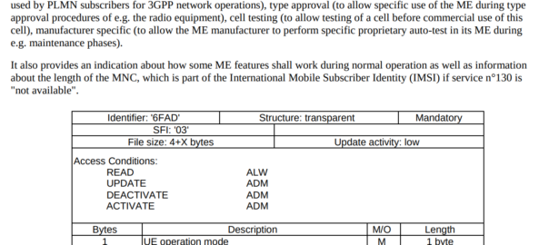
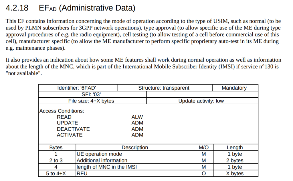
The SUPI (Subscription Permanent Identifier) replaces the IMSI as the unique identifier for each Subscriber in 5G.
One of the issues with using IMSI in LTE/EUTRAN is there were a few occasions where the IMSI was sent over the clear – meaning the IMSIs of subscribers nearby could be revealed to anyone listening.
So what is a SUPI and what does it look like? Well, most likely it’ll look like an IMSI – 15 or 16 digits long, with the MCC/MNC as the prefix.
If you’re using a non-3GPP RAT it could be a RFC 4282 Network Access Identifier, but if it’s on a SIM card or in a Mobile Device, it’s probably exactly the same as the IMSI.
SUCI Subscription Concealed Identifier
Our SUPI is never sent over the air in the clear / plaintext, instead we rely on the SUCI (Subscription Concealed Identifier) for this, which replaces the GUTI/TMSI/IMSI for all plaintext transactions over the air.
Either the UE or the SIM generate the SUCI (if it’s done by the SIM it’s much slower), based on a set of parameters defined on the SIM.
The SUCI has to be generated by the UE or SIM in a way the Network can identify the SUPI behind the SUCI, but no one else can.
In LTE/EUTRAN this was done by the network randomly assigning a value (T-MSI / GUTI) and the network keeping track of which randomly assigned value mapped to which user, but initial attach and certain handovers revealed the real IMSI in the clear, so for 5G this isn’t an option.
So let’s take a look at how SUCI is calculated in a way that only the network can reveal the SUPI belonging to a SUCI.
The Crypto behind SUCI Calculation
As we’ll see further down, SUCI is actually made up of several values concatenated together. The most complicated of these values is the Protection Scheme Output, the cryptographically generated part of the SUCI that can be used to determine the SUPI by the network.
Currently 3GPP defines 3 “Protection Scheme Profiles” for calculating the SUCI.
Protection Scheme Identifier 1 – null-scheme
Does nothing. Doesn’t conceal the SUPI at all. If this scheme is used then the Protection Scheme Output is going to just be the SUPI, for anyone to sniff off the air.
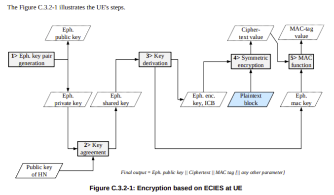
Protection Scheme Identifier 2 & 3 – ECIES scheme profile A & B
The other two Protection Scheme Identifiers both rely on Elliptic Curve Integrated Encryption Scheme (ECIES) for generation.
So if both Profile A & Profile B rely on Elliptic Curve Integrated Encryption Scheme, then what’s the difference between the two?
Well dear reader, the answer is semantics! There’s lots of parameters and variables that go into generating a resulting value from a cryptographic function, and Profile A & Profile B are just different parameters being used to generate the results.
For crypto nerds you can find the specifics in C.3.4.1 Profile A and C.3.4.1 Profile B outlined in 3GPP TS 33.501.
For non crypto nerds we just need to know this;
When the SIM is generating the SUCI the UE just asks for an identity by executing the GET IDENTITY command ADF against the SIM and uses the response as the SUCI.
When the UE is generating the SUCI, the UE gets the SUCI_Calc_Info EF contents from the SIM and extracts the Home Network Public Key from it’s reply. It uses this Home Network Public Key and a freshly created ephemeral public/private key pair to generate a SUCI value to use.
Creating the SUCI
After generating a Protection Scheme Output, we’ll need to add some extra info into it to make it useful.
The first digit of the SUCI is the SUPI type, a value of 0 denotes the value contained in the Protection Scheme Output is an IMSI, while 1 is used for Network Access Indicator for Non 3GPP access.
Next up we have the Home Network Identifier, which in a mobile environment is our PLMN (MCC/MCC).
Then a Routing Indicator, 1-4 digits long, is used with the Home Network Identifier to route the Authentication traffic to the UDM that contains that subscriber’s information, ie you may have MVNOs with their own UDM. If the routing indicator of 10 is assigned to the MVNOs SIMs then the AMF can be set to route traffic with a routing indicator of 10 to the UDM of the VMNO.
The Protection Scheme we covered earlier, with the 3 types of protection scheme (Null & two relying on Elliptic Curve Integrated Encryption Scheme).
Home Network Public Key Identifier identifies which Public Key was used to generate the Protection Scheme Output.
Finally we have the Protection Scheme Output which we covered generating in the previous session.
Usage in Signaling
The SUPI is actually rarely used beyond the initial attach to the network.
After authenticating to the network using AKA and the SUCI, in 5GC, like in LTE/EUTRAN, a shorter GUTI is used which further protects the subscriber’s identity and changes frequently.
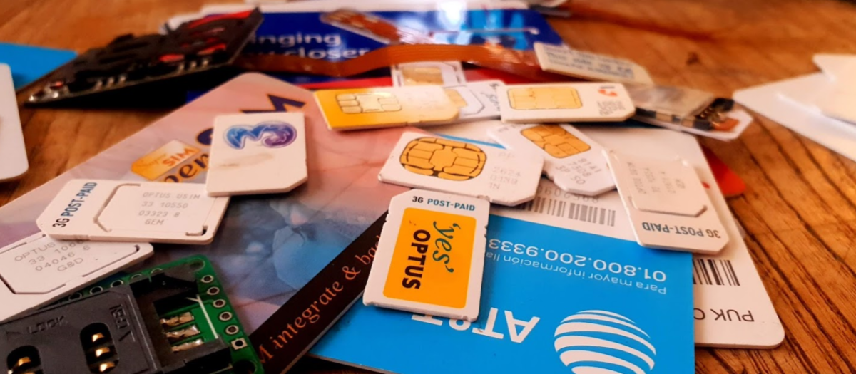
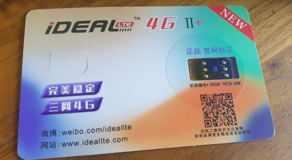
There’s a lot of “Magic Unlock SIM” products online; IdeaLTE, U-SIM LTE 4G Pro II (sic), UltraSIM, TurboSIM etc, with no real description as to what they are or how they work,
They claim to do something to do with unlocking iPhones, but with little other info.
Being interested in SIM technology, and with no real idea what they are I ordered a few.
What are they?
They’re man-in-the-middle SIM card devices that are able to intercept requests from the UE / baseband of the device.
They sit on top of the real SIM card, between it and the SIM Slot.
One of the ones I bought had a sticker on it that helped stick it into place, the other just sat above the SIM below the phone.
This means when the UE sends the APDU to request some data from the card, the SIM-shim device analyses the request, and if it matches the rules on the SIM-Shim, intercepts it and responds with something else, ignoring the data the real SIM card would send back and injecting its own,
The use for this seems to be to do with how Apple does Carrier Locking on the iPhone. It seems in the iPhone carrier settings are ranges of ICCIDs used by the different carriers for their SIMs, and uses that to identify the carrier of the SIM.
With this information it’s able to determine if the SIM card is from the carrier the iPhone is locked to or not,
Now you’re probably seeing the value in this attack – By intercepting the request for the ICCID of the card, and instead of responding with the real ICCID, the SIM-Shim intercepts the request and sending back an ICCID of a card the iPhone is carrier locked to, the iPhone is tricked into thinking it’s talking to a card from the carrier the phone is locked to.
So let’s say we’ve got an iPhone from Carrier A, and they’ve told Apple their SIM cards have ICCIDs in the range from 0001 to 0005, If I put a SIM card with the ICCID 0003 the iPhone knows it’s a SIM from Carrier A, If I put in a SIM card with ICCID 9999 the iPhone knows the SIM is not from carrier A, and therefore prevents me from using the iPhone, But if I put in one of these SIM Shims, when the iPhone ask the ICCID of the card, the SIM Shim will respond with an ICCID we set on it, so if we want to use SIM with ICCID 9999 in a phone locked to Carrier A, all we’ve got to do is setup the SIM-Shim to respond with ICCID of 0001 for example.
Phew. Ok, that’s the short run down on how it works (There’s more to activating iPhones but we’re here to talk about SIMs!).
The Hardware
So physically these are “shims” – they sit between the real SIM and the mobile phone and intercept the communications.
It blows my mind that someone’s been able to manufacture these in such a small form factor.
But there is one rather glaring flaw in having a tiny wafer that sits on top of your regular SIM, and that is if it pops up/down/ get loose and become hellish to get out.
I found their insertion and removal is a bit of a game of Russian roulette as to if it will go in, or come out, without brute force and potential damage to the device.
In the end on one iPhone I had to force the SIM tray out with a set of needle nose pliers, and my little SIM-shim was pretty beaten up and no longer useable. RIP SIM-Shim 1.
I think this may have been an early version of the same thing? Or possibly to allow dual SIM on an iPhone?
The Software
Interacting with the IdealLTE for example, is via SIM Toolkit Application for managing ICCIDs.
You can set any ICCID you want, which is cool, but limited.
Unfortunately I haven’t been able to find any way of messing with these to allow interception / replacement for other APDUs, for example if you could change the Administrative Domain to get higher access to the network.
I will at some stage put these into a SIMtrace and compare the output, and have a poke around and see if I can find anyway to change / update these, or if there’s any APDUs it responds interestingly to.
Unfortunately I’ve actually lost the new unit I had to replace the one I broke, they are very very small…
I reached out to the developer / vendor but they seem to go dark and popup under a different name, I’m not holding my breath…