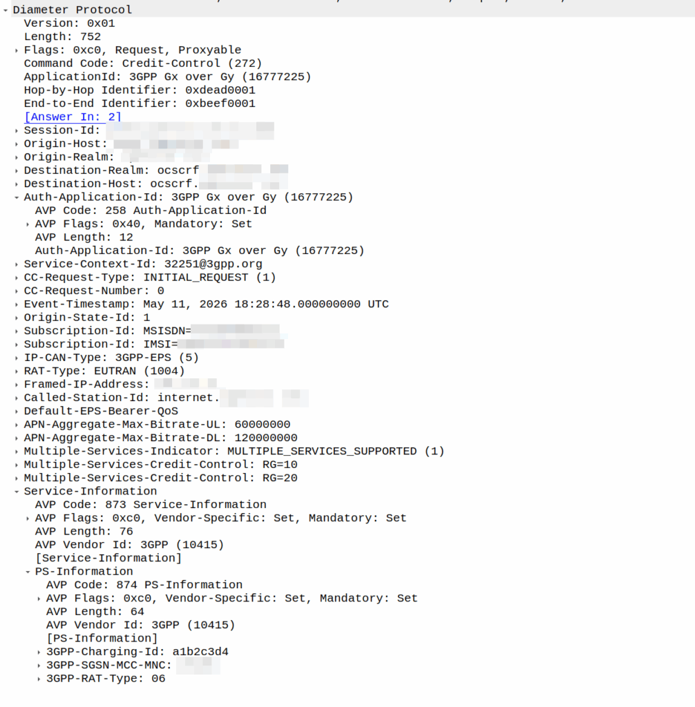
I was recently asked by a potential customer if we supported Gx over Gy.
I’d never heard of this before, so I gave my standard “If it’s in the spec we should support it, but I’ll check” answer, and got them to send me a PCAP, which I’ve got.
This is weird.
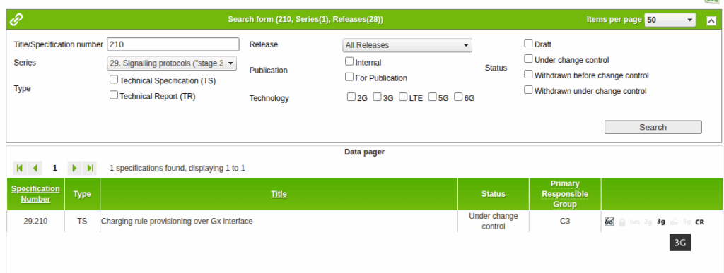
So for starers, Protocoldex has nothing for this application ID (16777225), even though it has all the LTE diameter specs.
The last version was from 2006, in 3GPP release 6, which is two years before LTE was standardized in Release 8. The word LTE does not appear in the doc or in the metadata tags.
It speaks of TPF (Traffic Plane Function) and TPF (Charging Rules Function).
LTE is “Long Term Evolution” – In later releases this draft TPF would evolve into the PGW (before the PGW-C / PGW-U divorce) and the TPF would go on to become the PCRF (and save spring break).
Reading through these early specs is like looking at Homo Eructs (get your mind out of the gutter) and knowing it evolves into Homo Sapiens.
So what does Gx over Gy do? Well, the concept is pretty straightforward, rather than needing a Sy interface between the PCRF and OCS, you can provision policy rules from the OCS, rather than on the PCRF.
So what network functions should implement this standard? Well, the P-GW specs do not reference this as something that’s included in the P-GW, nor is it in the GGSN – This was a “gooch” spec between the hypothetical standards land and real world implementations.
So will we be implementing it? Probably not. But an interesting bit of archaeology and a look through the genealogy of 3GPP.
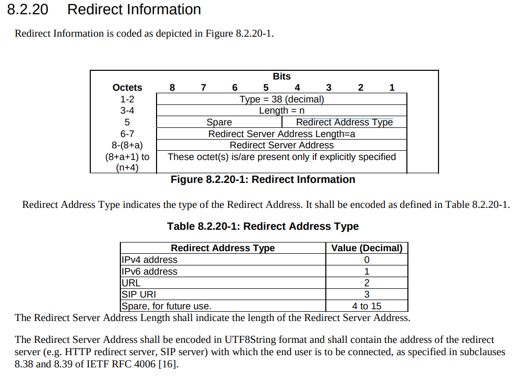
There’s a cool feature in PFCP that allows you to redirect traffic, which I’ve written about before.
But there’s a funky thing that’s left me scratching my head, in the Redirect information IE, you can set a SIP URI.
Snippet from TS 3GPP TS 29.244
That’d be great and all, but PFCP is all about packets not about calls.
So what’s the deal?
Had I uncovered some Machiavellian plot to move channel-associated-signaling onto PFCP instead of TDM links as God intended?
Well, no…
The Redirect Information in PFCP comes from the Redirect Information in Diameter, that’s how your OCS can tell your SMF or your PGW-C (or your TAS) – hey this session is all out of usage, and should be redirected.
Of course, PFCP is just all about packets, but Diameter has a foot in both camps, Gy and Ro are both on Diameter.
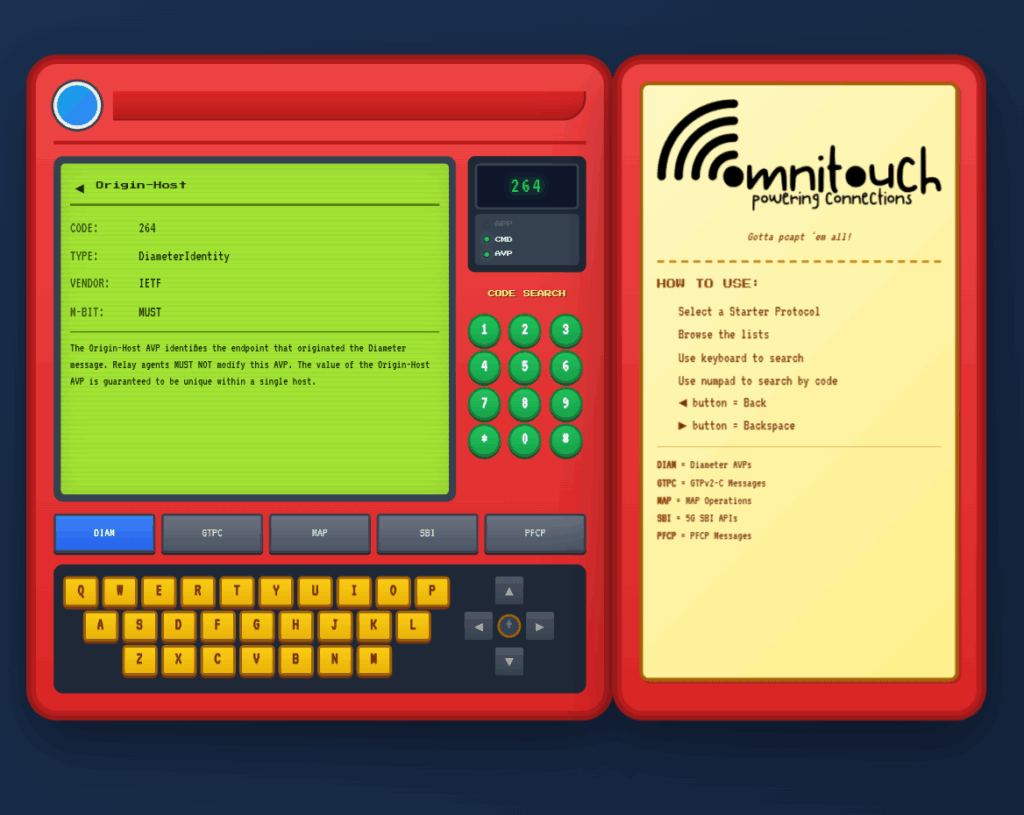
I do a lot of protocol testing, writing Diameter/PFCP/GTP-C etc, and spend a lot of time referencing the standards.
So I built this – Inspired by a 1990s video game / TV / Playing card franchise online reference tool, but rather than identifying pocket monsters, it’s identifying AVPs and stuff
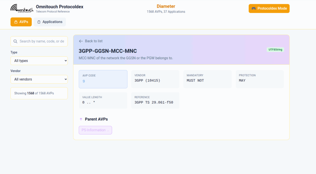
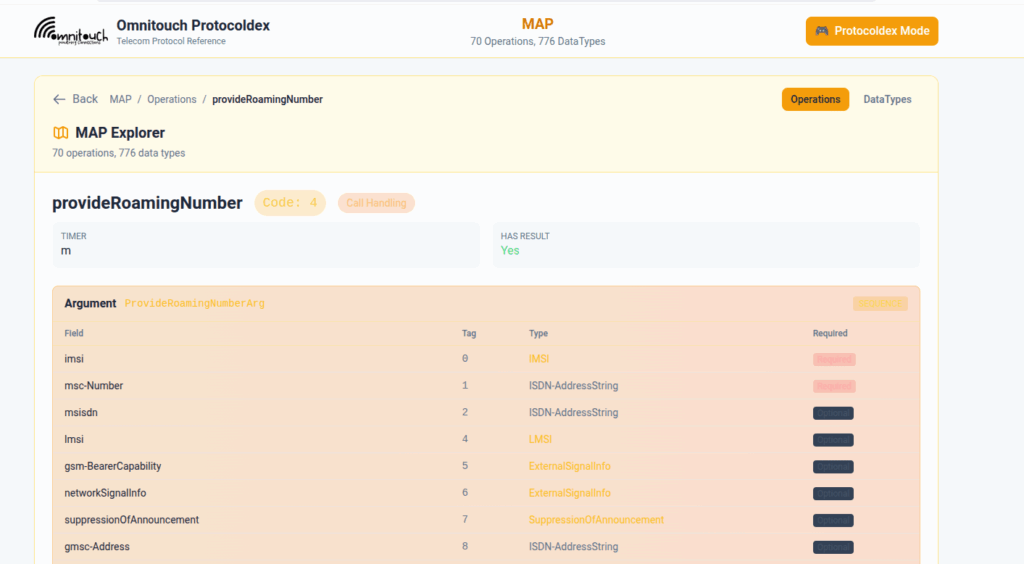
You can punch in the AVP code, AVP name, description, etc, for Diameter, PFCP, GTP-C, MAP or SBI and see all the details to go with it.
I’ve been using it a heap, hopefully some of you might find it useful:
A concept that’s always been a bit unclear to me was how the Sh Profile, XCAP data for call forwarding / barring and RepositoryData all fit together.
Let’s start off with the basics.
The Diameter Sh interface sits between an Application Server (Typically TAS, SMSc, XCAP server, etc) and the HSS.
This AS can run a Diameter User Data Request to get the contents of Sh Data, which is returned in the User Data AVP (702) for a given subscriber.
Application Servers can also subscribe to be notified of changes in the Sh data on the HSS, by sending a Subscriber Notification Request, and when the data changes they’ll get a “Push Notification Request” to inform them of the change.
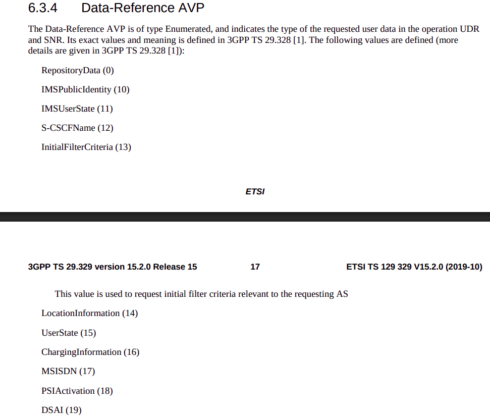
When sending this User Data Request the AS can specify what data it wants to get returned, for example an AS might want to know the current S-CSCF of a given subscriber, in which case, the AS would set the DataReference AVP (703) to 12 for S-CSCFName.
Not the complete list…
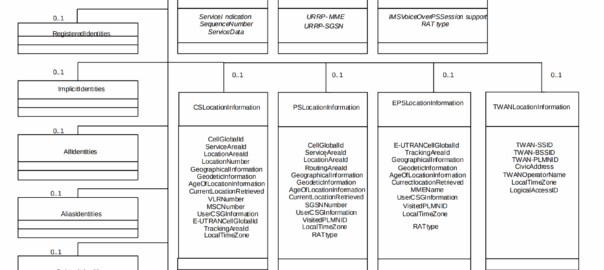
The the AS can request can be public and private identities (IMSIs and MSISDNs), location in the PS and CS networks, TADS info, SRVCC parameters, etc, etc.
Data like TADS Info, CS and PS network location, Public and Private identities, come from the HSS and cannot be modified, these values either come from the static subscriber definition in the HSS (what was set when provisioning the subscriber), or based on the subscriber’s state (ie where they’re registered on the network).
RepositoryData
But there is a section of data we can request the HSS return called RepositoryData which can be modified/updated by the end user or other applications in the network (Modified by ASes), via a Profile Update Request.
This data is where we put the call forwarding, call barring, caller ID presentation/restriction info – The HSS doesn’t really care what is stored in RepositoryData, it’s just a transparent place to store this data.
Think of it as a simple folder containing text files, each text file has a name (ServiceNotification) which allows us to reference the blobs of data by name, a SequenceNumber to identify duplicates, and then the actual contents of the file itself ServiceData.
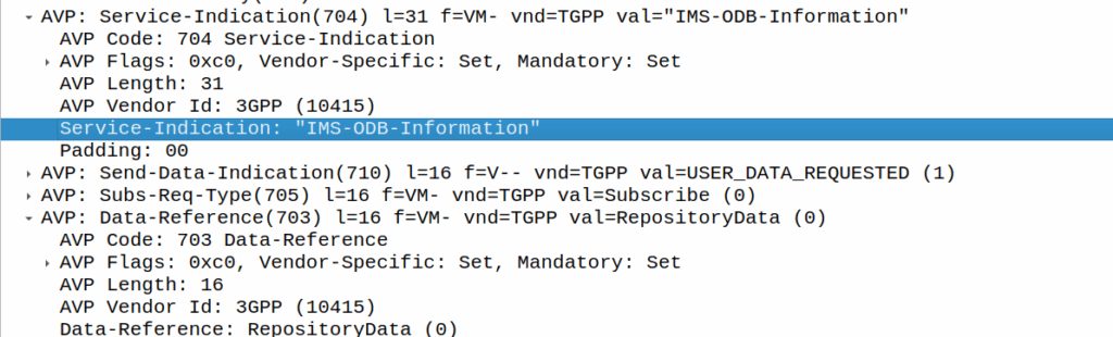
We can then request the contents of these files from the HSS by calling DataReference of RepositoryData and setting the ServiceIndication to be the “file” we want returned to the AS by the HSS.
For example, if the Data-Reference AVP is set to zero (Repository Data) and the Service-Indicator AVP is set to “IMS-ODB-Information” the HSS will return the data for the file IMS-ODB-Information of repository data.
This RepositoryData is just “transparent” storage of XML data by the HSS, and this is where we’d put Call Forwarding, Operator Defined Barring and CLI presentation/restriction parameters.
In theory you could also store 3rd party custom unstructured data here (Move over AWS S3 buckets, I’m moving all my storage to Diameter!), but it’s not commonly used beyond call routing parameters.
The two most common types of ServiceIndication keys you’ll see stored in RepositoryData are MMTEL-Services and IMS-ODB-Information. Each of these are defined by their own XML spec, but the MMTel-Services key is where all of our Call Forwarding, Caller ID Presentation/Restriction parameters live, while IMS-ODB-Information contains the parameters for Operator Defined barring – Both of these XML definitions we’ll dive into in a post of their own, but for now all you need to remember is that they’re stored transparently as XML on the HSS.
An example use case of this would be when a user wants to manage their call forwarding data via XCAP. When the user pulls up the Call Forwarding menu on their phone, the first entry point will be the XCAP Server (AS) to get all the User Data for MMTelServices, so it’ll do that via a Diameter User Data Request with the DataReference set to RepositoryData and the ServiceIndication set to MMTel-Service so the XCAP server can pass the full XCAP XML body to the UE.
The UE can then update this data, and the XCAP server just sends a Profile Update Request to push the updated XML to be stored on the HSS.
Fitting this all Together
Data sent to the AS by the HSS will always include the <Sh-Data> XML, but the child keys within it depend on the data the AS requested under the Data-Reference.
If we requested IMSI as the DataReference, then the returned XML might look like:
<Sh-Data>
 <imsi>9990112345677</imsi>
</Sh-Data>
Likewise, if you requested IMSPublicIdentity as the DataReference you’d get:
The spec goes into full detail on all the possible keys, but in short, when the AS queries the data for the provided DataReference, the HSS sends back an Sh-Data XML body containing at a minimum those keys.
Up until this point in the series, I’ve tried to hide all the complexity of CGrateS, so people following along can see some progress and feel like they’re making it somewhere with CGrateS, but it’s time to tear off the plaster and talk about the actual concepts, about what’s under the hood, and how all the components interact, as it’ll make it much easier then for us to learn more about how to use CGrateS.
This will be the last post in the “CGrateS in Baby Steps” series (Which I started in 2022), if you’ve made it this far congratulations, all the future posts will be on specific topics and build upon the concepts we’ve covered here.
This took me a while to grasp – CGrateS is both crazy complex and beautifully simple, but getting to the stage where you can “see through the matrix” on CGrateS and see the beautiful simplicity involves a bit of understanding how everything fits together.
Once you realize once you can see the pattern, and understand the building blocks, everything else CGrateS related becomes super simple.
Agents
in CGrateS Agents are consumers of the services. That’s a super generic answer, but let’s take a closer look at what that actually means with some examples:
Diameter is a protocol that can be used for Online Charging.
CGrateS has a common interface for API calls that can perform Online Charging.
The CGrateS Diameter Agent translates between Diameter on one side, and CGrateS API calls on the other.
Likewise, if we want to speak Radius, we can use the CGrateS Radius Agent, this translates between RADIUS and the CGrateS API calls.
FreeSWITCH, Asterisk and Kamailio don’t use specific protocols like Diameter or Radius, but rather modules or plugins to connect that application to a CGrateS Agent, and they all just end up talking the same CGrateS API calls.
Lastly, there’s even an HTTP agent so you could define your own agent to talk another protocol if you wanted to use CGrateS for anything else (We’ve been playing with CAMEL based charging with CGrateS and 5GC charging).
The config for each of the CGrateS Agents happens in the cgrates.json config file (Typically in /etc/cgrates).
Because the Agents just translate everything into API calls, logic for billing a call from FreeSWITCH is the same as for Diameter, the same as for RADIUS, the same as for SIP, the same as for Asterisk.
The Agents just translate all the domain-specific stuff into the common CGrateS RPC API, which we’ve been working with up to this point.
This is key part to understand; because once you understand how to do the CGrateS part, moving from Asterisk to FreeSWITCH, to DNS, to RADIUS, to any other Agent, it’s all the same to you.
The Agents just translate domain-specific stuff (Diameter requests, CSV files, Asterisk Calls, FreeSWITCH calls, etc, etc) and act as a translator to translate these requests into CGrateS RPC API calls.
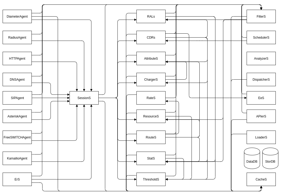
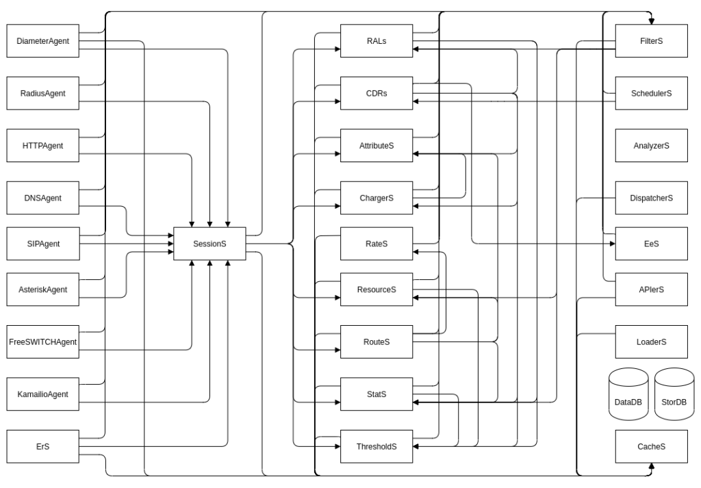
On the left side of the image below are the Agents, and on the right side, the Subsystems that do stuff with things.
Subsystems
So with these API calls, where do they go, what do they do?
Well, it’s the Subsystems that do the things.
What things?
Well, everything of use.
Each subsystem has a purpose, AttributeS transforms stuff, EeS exports CDRs, RALs applies our charging logic, CDRs writes CDRs to StorDB, etc, etc.
In each event we can set flags to denote which subsystems it should be routed to, and we can set the links between components in our cgrates.json file.
Based on the flags, we pass events between these subsystems.
Events
So our Agents create the API calls, which contain Events, which are JSON RPC calls.
They look like all the API examples we’ve played with, because that’s exactly what they are.
We can access them via the JSON RPC API, but when you start a call on Kamailio, the Kamailio Agent generates a JSON RPC API call containing an Event into CGrateS for that call on Kamailio.
When you send a DNS request, the DNS Agent translate this DNS request into a CGrateS JSON RPC API containing the event for the DNS request.
Let’s take an example, we’re going to use the ErS as it’s the simplest to demonstrate with.
So if you setup your enviroment per the tutorial above (but don’t load the CSV yet), we’ll start running some experiments…
Anatomy of an Event
We can “sniff” the events bouncing around between the Agent and the various Subsystems in real time, by using ngrep:
sudo ngrep -t -W byline port 2012 or port 2080 or port 8021 or port 2014 or port 2053 -d any
So let’ we’ve got ngrep running, we can move our CSV file in to be processed in another tab.
Plonking the CSV file into the path ERS is monitoring will mean the ErS Agent will generate a CGrateS JSON RPC “event” for each row in the file, it’ll look something like this:
Sidebar – you’re going to spend a lot of time with `ngrep`.
Alright, that event probably looks familiar, after all, it’s the same structure as the API requests we’ve made to CGrateS so far, to set rates and handle accounts.
But what we’re witnessing here isn’t us making an API request to the JSON RPC interface from a Python script, it’s the ERS Agent inside CGrateS, calling CGrateS.
The ERS Agent inside CGrateS reads the CSV file we dropped in, and based on what we had set in the ERS section of the CGrateS config file (cgrates.json), the ERS Agent create JSON RPC events and sent it to CGrateS for processing.
You may be thinking “Wow, the ERS Agent is really dumb, it just sends an API request (events)”, and you’d be right.
We could replace the ERS Agent with a Python script to read the CSV and send the same request, and we’d get the exact same outcome, but CGrateS is mostly “batteries included” so we don’t have to.
Ok, so you’ve heard me drum in the fact that Agents are pretty simple, and all they do is make JSON RPC requests for the event which are sent to CGrateS. So now what happens?
Well, the event is calling CDRsV1.ProcessEvent, so that means the Event is passed by CGRengine to the CDRs subsystem.
What does CDRs subsystem do with it? Well, that’s going to depend on what’s in our cgrates.json config file,
In the above example, CDRs is setup with connections to the different subsystems, AttributeS, Chargers and RALs are all the subsystems linked from here.
Having these links here does not force the Event to always route to these Subsystems, but unless we’ve got the links there, the Event won’t be able to get routed from CDRs to that subsystem if we want it to.
But we can see what’s going to happen with this request based on our CDRsV1.ProcessEvent event, it’s got Flags set to rals, so we know it wants RALs to be called.
So looking in ngrep we see our CDRsV1.ProcessExternalCDR event makes it to the CDRs module with ID 1.
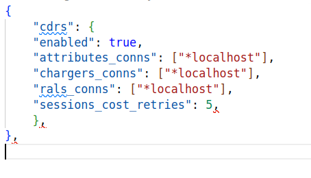
The API call has flags set to *rals so the CDRs will call RALs , and inside our config the CDRs section has a link in the config (shown in the image below) to RALs (rals_conns) – if we didn’t have that link, CGrateS wouldn’t know how to connect to RALs, and the event would fail.
Note at the bottom the APIOpts section tells us this API call was made by the *cdrs subsystem and the ID is 2 (This is a different request to the original CDRsV1.ProcessExternalCDR request which had ID 1 – we can use this to match responses to requests).
Again, because our config also includes links ChargerS and RALS subsystems, we’ll see requests to (you guessed it) ChargerS (The ChargerSv1.ProcessEvent) and RALS (Responder.GetCost).
# T 2024/12/22 09:09:47.465711 127.0.0.1:2012 -> 127.0.0.1:50456 [AP] #414 {"id":4,"result":{"Category":"call","Tenant":"cgrates.org","Subject":"61812341234","Account":"61412341234","Destination":"61812341234","ToR":"*voice","Cost":14,"Timespans":[{"TimeStart":"2024-01-01T01:00:00+11:00","TimeEnd":"2024-01-01T01:01:00+11:00","Cost":14,"RateInterval":{"Timing":{"ID":"*any","Years":[],"Months":[],"MonthDays":[],"WeekDays":[],"StartTime":"00:00:00","EndTime":""},"Rating":{"ConnectFee":0,"RoundingMethod":"*up","RoundingDecimals":4,"MaxCost":0,"MaxCostStrategy":"","Rates":[{"GroupIntervalStart":0,"Value":14,"RateIncrement":60000000000,"RateUnit":60000000000}]},"Weight":10},"DurationIndex":60000000000,"Increments":[{"Duration":0,"Cost":0,"BalanceInfo":{"Unit":null,"Monetary":null,"AccountID":""},"CompressFactor":1},{"Duration":60000000000,"Cost":14,"BalanceInfo":{"Unit":null,"Monetary":null,"AccountID":""},"CompressFactor":1}],"RoundIncrement":null,"MatchedSubject":"*out:cgrates.org:call:*any","MatchedPrefix":"618","MatchedDestId":"Dest_AU_Fixed","RatingPlanId":"RatingPlan_VoiceCalls","CompressFactor":1}],"RatedUsage":60000000000,"AccountSummary":null},"error":null}
What we’re seeing is the CDRs module, calling RALs, to get the cost information for this event.
Finally the CDRsV1.ProcessEvent that was initially sent by ErS gets a result (we can find the result to the request as it’ll have the same id parameter)
So that’s it, that’s the secret sauce – CGrateS is just a bunch of little APIs we combo together to create something great.
Recap
Agents translate data sources into API calls.
Each little API belongs to a Subsystem, like ChargerS, AttributeS or RALs, and we can chain them together in our config file or through the flags in the API request.
Once you’ve got your head wrapped around this, everything in CGrateS becomes way easier.
From now on I’ll pivot to talking about specific modules, and how we use them, starting with AttributeS (which I wrote last year while still drafting this), and diving into how to use each module in more detail.
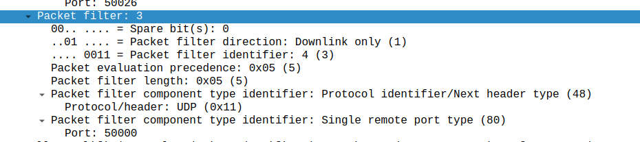
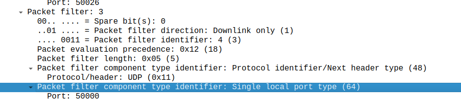
What is included in the Charging Rule on Gx ultimately turns into a Create Bearer Request on GTPv2-C.
But the mapping it’s always obvious, today I got stuck on the difference between a Single remote port type, and a single local port type, thinking that the Packet Filter Direction in the TFT controlled this – It doesn’t – It’s controlled by the order of your Traffic Flow Template rule.
Input TFT:
"permit out 17 from any 50000 to any"
Leads to Packet filter component type identifier: Single remote port type
Whereas a TFT of:
permit out 17 from any to any 50000
Leads to Packet filter component type identifier: Single local port type (64)
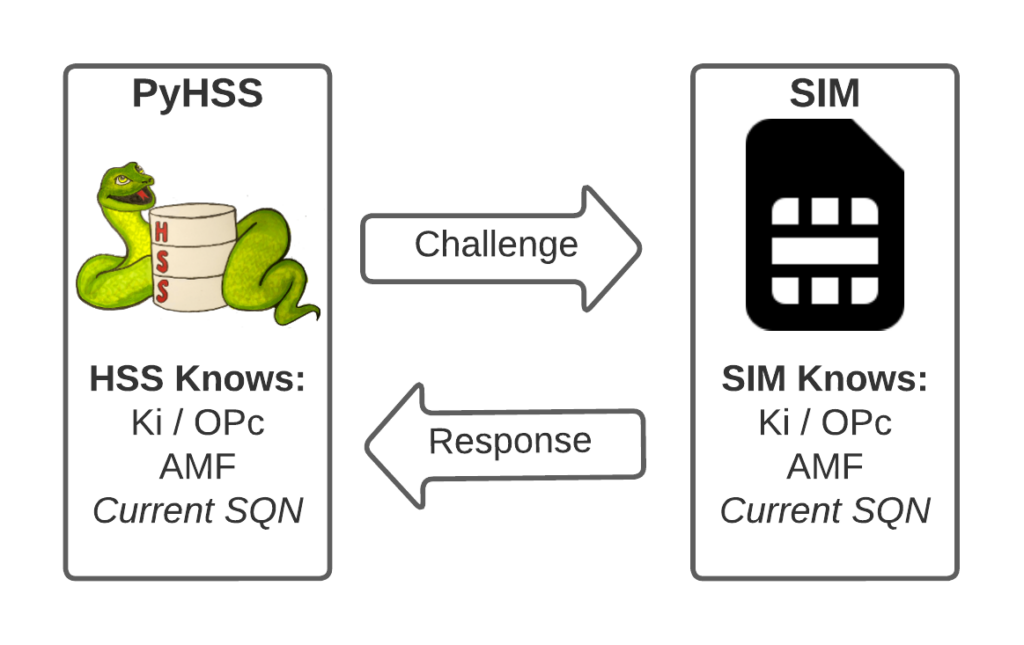
I’ve written about Milenage and SIM based security in the past on this blog, and the component that prevents replay attacks in cellular network authentication is the Sequence Number (Aka SQN) stored on the SIM.
Think of the SQN as an incrementing odometer of authentication vectors. Odometers can go forward, but never backwards. So if a challenge comes in with an SQN behind the odometer (a lower number), it’s no good.
Why the SQN is important for Milenage Security
Every time the SIM authenticates it ticks up the SQN value, and when authenticating it checks the challenge from the network doesn’t have an SQN that’s behind (lower than) the SQN on the SIM.
Let’s take a practical example of this:
The HSS in the network has SQN for the SIM as 8232, and generates an authentication challenge vector for the SIM which includes the SQN of 8232. The SIM receives this challenge, and makes sure that the SQN in the SIM, is equal to or less than 8232. If the authentication passes, the new SQN stored in the SIM is equal to 8232 + 1, as that’s the next valid SQN we’d be expecting, and the HSS incriments the counters it has in the same way.
By constantly increasing the SQN and not allowing it to go backwards, means that even if we pre-generated a valid authentication vector for the SIM, it’d only be valid for as long as the SQN hasn’t been authenticated on the SIM by another authentication request.
Imagine for example that I get sneaky access to an operator’s HSS/AuC, I could get it to generate a stack of authentication challenges that I could use for my nefarious moustache-twirling purposes whenever I wanted.
This attack would work, but this all comes crumbling down if the SIM was to attach to the real network after I’ve generated my stack of authentication challenges.
If the SQN on the SIM passes where it was when the vectors were generated, those vectors would become unusable.
It’s worth pointing out, that it’s not just evil purposes that lead your SQN to get out of Sync; this happens when you’ve got subscriber data split across multiple HSSes for example, and there’s a mechanism to securely catch the HSS’s SQN counter up with the SQN counter in the SIM, without exposing any secrets, but it just ticks the HSS’s SQN up – It never rolls back the SQN in the SIM.
The Flaw – Draining the Pool
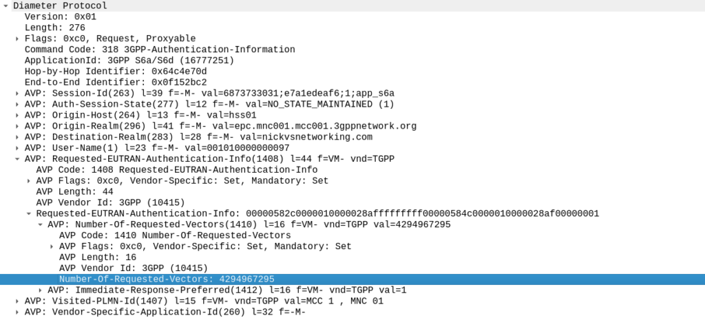
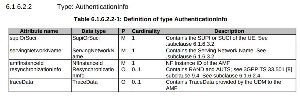
The Authentication Information Request is used by a cellular network to authenticate a subscriber, and the Authentication Information Answer is sent back by the HSS containing the challenges (vectors).
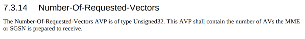
When we send this request, we can specify how many authentication challenges (vectors) we want the HSS to generate for us, so how many vectors can you generate?
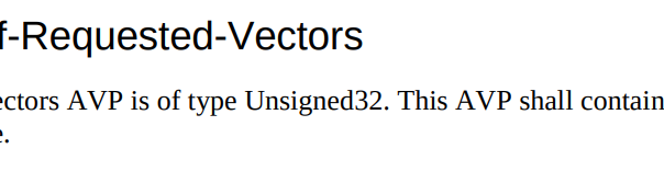
TS 129 272 says the Number-of-Requested-Vectors AVP is an Unsigned32, which gives us a possible pool of 4,294,967,295 combinations. This means it would be legal / valid to send an Authentication Information Request asking for 4.2 billion vectors.
It’s worth noting that that won’t give us the whole pool.
Sequence numbers (SQN) shall have a length of 48 bits.
TS 133 102
While the SQN in the SIM is 48 bits, that gives us a maximum number of values before we “tick over” the odometer of 281,474,976,710,656.
If we were to send 65,536 Authentication-Information-Requests asking for 4,294,967,295 a piece, we’d have got enough vectors to serve the sub for life.
Except the standard allows for an unlimited number of vectors to be requested, this would allow us to “drain the pool” from an HSS to allow every combination of SQN to be captured, to provide a high degree of certainty that the SQN provided to a SIM is far enough ahead of the current SQN that the SIM does not reject the challenges.
Can we do this?
Our lab has access to HSSes from several major vendors of HSS.
Out of the gate, the Oracle HSS does not allow more than 32 vectors to be requested at the same time, so props to them, but the same is not true of the others, all from major HSS vendors (I won’t name them publicly here).
For the other 3 HSSes we tried from big vendors, all eventually timed out when asking for 4.2 billion vectors (don’t know why that would be *shrug*) from these HSSes, it didn’t get rejected.
This is a lab so monitoring isn’t great but I did see a CPU spike on at least one of the HSSes which suggests maybe it was actually trying to generate this.
Of course, we’ve got PyHSS, the greatest open source HSS out there, and how did this handle the request?
Well, being standards compliant, it did what it was asked – I tested with 1024 vectors I’ll admit, on my little laptop it did take a while. But lo, it worked, spewing forth 1024 vectors to use.
So with that working, I tried with 4,294,967,295…
And I waited. And waited.
And after pegging my CPU for a good while, I had to get back to real life work, and killed the request on the HSS.
In part there’s the fact that PyHSS writes back to a database for each time the SQN is incremented, which is costly in terms of resources, but also that generating Milenage vectors in LTE is doing some pretty heavy cryptographic lifting.
The Risk
Dumping a complete set of vectors with every possible SQN would allow an attacker to spoof base stations, and the subscriber would attach without issue.
Historically this has been very difficult to do for LTE, due to the mutual network authentication, however this would be bypassed in this scenario.
The UE would try for a resync if the SQN is too far forward, which mitigates this somewhat.
Cryptographically, I don’t know enough about the Milenage auth to know if a complete set of possible vectors would widen the attack surface to try and learn something about the keys.
Mitigations / Protections
So how can operators protect ourselves against this kind of attack?
Different commercial HSS vendors handle this differently, Oracle limits this to 32 vectors, and that’s what I’ve updated PyHSS to do, but another big HSS vendor (who I won’t publicly shame) accepts the full 4294967295 vectors, and it crashes that thread, or at least times it out after a period.
If you’ve got a decent Diameter Routing Agent in place you can set your DRA to check to see if someone is using this exploit against your network, and to rewrite the number of requested vectors to a lower number, alert you, or drop the request entirely.
Having common OP keys is dumb, and I advocate to all our operator customers to use OP keys that are unique to each SIM, and use the OPc key derived anyway. This means if one SIM spilled it’s keys, the blast doesn’t extend beyond that card.
In the long term, it’d be good to see 3GPP limit the practical size of the Number-of-Requested-Vectors AVP.
2G/3G Impact
Full disclosure – I don’t really work with 2G/3G stacks much these days, and have not tested this.
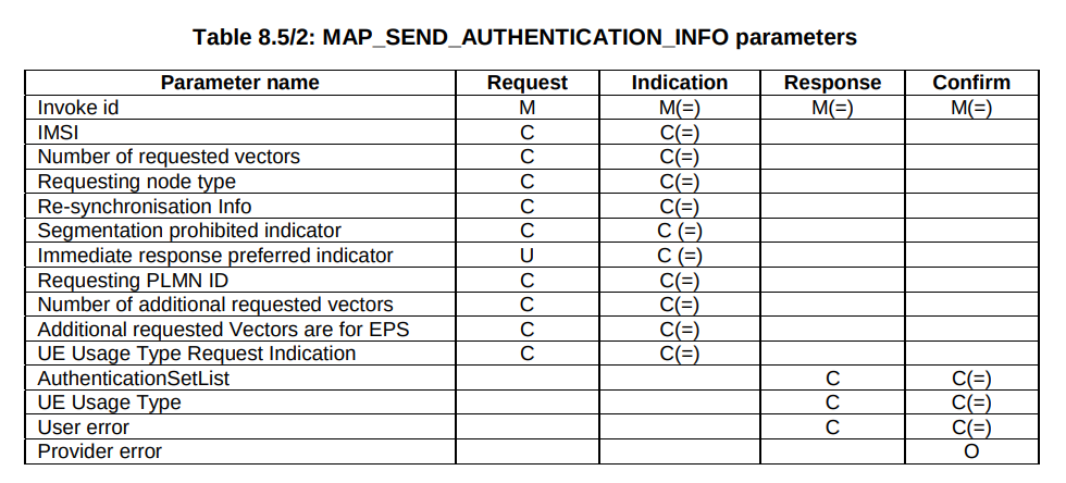
MAP is generally pretty bandwidth constrained, and to transfer 280 billion vectors might raise some eyebrows, burn out some STPs and take a long time…
But our “Send Authentication Info” message functions much the same as the Authentication Information Request in Diameter, 3GPP TS 29.002 shows we can set the number of vectors we want:
5GC Vulnerability
This only impacts LTE and 5G NSA subscribers.
TS 29.509 outlines the schema for the Nausf reference point, used for requesting vectors, and there is no option to request multiple vectors.
Summary
If you’ve got baddies with access to your HSS / HLR, you’ve got some problems.
But, with enough time, your pool could get drained for one subscriber at a time.
This isn’t going to get the master OP Key or plaintext Ki values, but this could potentially weaken the Milenage security of your system.
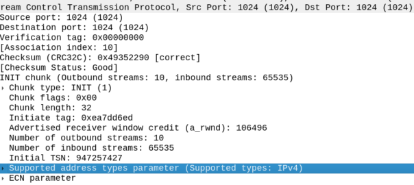
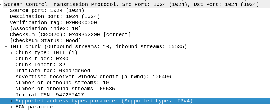
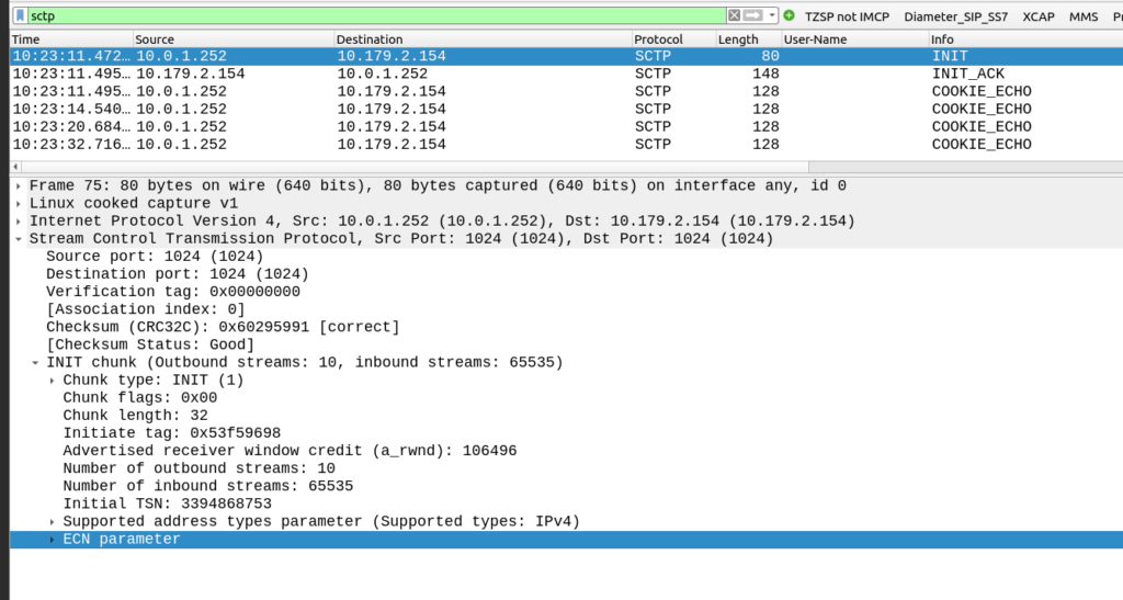
The other side of the SCTP connection didn’t like my SCTP parameters.
My SCTP INIT looked like this:
By default, Linux includes support for the ECN and SupportedAddressTypes parameters in the SCTP INIT.
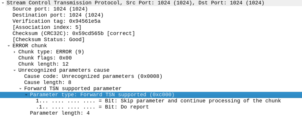
But the other side did not like this, it sent back an ERROR stating that:
Okay, apparently it doesn’t like the fact that we support Forward Transmission Sequence Numbers – So how to turn it off?
I’m using P1Sec’s PySCTP library to interact with the SCTP stack, and I couldn’t find any referneces to this in the code, but then I rememberd that PySCTP is just a wrapper for libsctp so I should be able to control it from there.
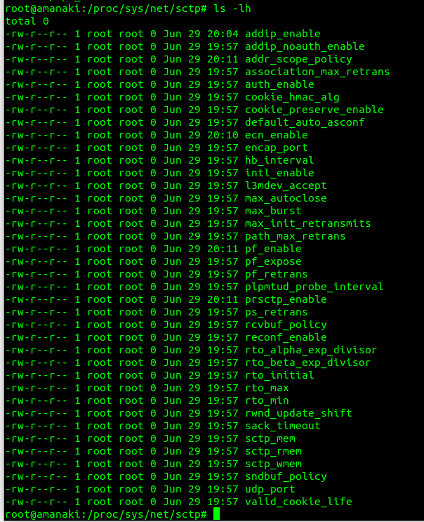
Inside /proc/sys/net/sctp we can see all the parameters we can control.
To disable the Forward TSN I need to disable the feature that controls it – Forward Transmission Sequence numbers are introduced in the Partial Reliability Extension (RFC 3758). So it was just a matter of disabling that with:
I generally do this with Python or via the Swagger UI for the Web UI, but here’s how we can create a fixed-line IMS subscriber in PyHSS, so we can register it with a softphone, without using EAP-AKA.
Firstly we create the AuC object for this password combo.
If you’re working with the larger SIM vendors, there’s a good chance they key material they send you won’t actually contain the raw Ki values for each card – If it fell into the wrong hands you’d be in big trouble.
Instead, what is more likely is that the SIM vendor shares the Ki generated when mixed with a transport key – So what you receive is not the plaintext version of the Ki data, but rather a ciphered version of it.
But as long as you and the SIM vendor have agreed on the ciphering to use, an the secret to protect it with beforehand, you can read the data as needed.
This is a tricky topic to broach, as transport key implementation, is not covered by the 3GPP, instead it’s a quasi-standard, that is commonly used by SIM vendors and HSS vendors alike – the A4 / K4 Transport Encryption Algorithm.
It’s made up of a few components:
K2 is our plaintext key data (Ki or OP)
K4 is the secret key used to cipher the Ki value.
K7 is the algorithm used (Usually AES128 or AES256).
It’s important when defining your electrical profile and the reuqired parameters, to make sure the operator, HSS vendor and SIM vendor are all on the same page regarding if transport keys will be used, what the cipher used will be, and the keys for each batch of SIMs.
Here’s an example from a Huawei HSS with SIMs from G&D:
We’re using AES128, and any SIMs produced by G&D for this batch will use that transport key (transport key ID 1 in the HSS), so when adding new SIMs we’ll need to specify what transport key to use.
In our last post we covered the basics of NB-IoT Non-IP Data Deliver (NIDD), and if that acronym soup wasn’t enough for you, we’re going to take a deep dive into the flows for attaching, sending, receiving and closing a NIDD session.
The attach for NIDD is very similar to the standard attach for wideband LTE, except the MME establishes a connection on the T6a Diameter interface toward the SCEF, to indicate the sub is online and available.
The NIDD Attach
The SCEF is now able to send/receive NIDD traffic from the subscriber on the T6a interface, but in reality developers don’t / won’t interact with Diameter, so the SCEF exposes the T8 API that developers can interact with to access an abstraction layer to interact with the SCEF, and then through onto the UE.
If you’re wondering what the status of Open Source SCEF implementations are, then you may have already guessed we’re working on one! PyHSS should have support for NB-IoT SCEF features in the future.
NB-IoT provides support for Non-IP Data Delivery (NIDD) over 3GPP Networks, but to handle this, some new network elements are introduced, in a home network scenario that’s the SCEF and the SCF/AS.
On the 3GPP side the SCEF it communicates to the MME via the T6a Interface, which is based upon Diameter.
On the side towards our IoT Service Consumers (in the standards referred to as “SCS/AS” or “Service Capabilities Server Application Servers” (catchy names as always), via the RESTful HTTP based T8 interface.
The start of the S1 Attach procedure is very similar to a regular S1 attach.
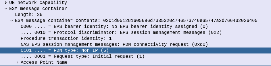
The initial S1 PDU Connectivity Request indicates in the ESM Message Container that the PDN Type is Non IP.
S1 PDU Connectivity Request from attach procedure
Other than that, the initial attach procedure looks very similar to the regular S1 attach procedure.
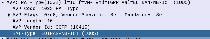
On the S6a interface the Update Location Request from the MME to the HSS indicates that this is an EUTRAN-NB-IoT Radio Access Type.
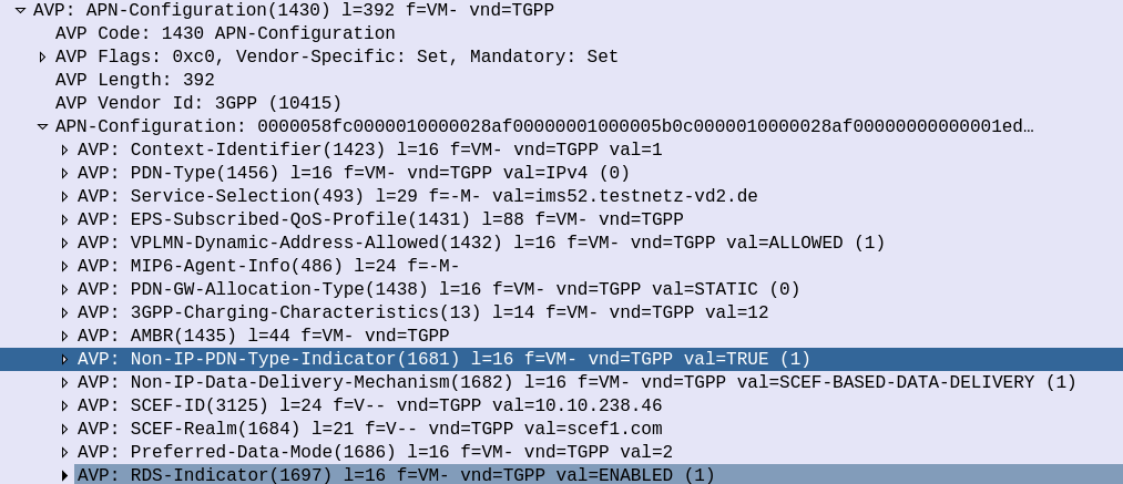
And the Update Location Answer APN Configuration contains some additional AVPs on the APN to indicate that the APN supports Non-IP-PDN-Type and that the SCEF is used for Data Delivery.
The SCEF-ID (Diameter Host) and SCEF-Realm (Diameter realm) to serve this user is also specified in the APN Configuration in the Update Location Answer.
This is how our MME determines where to send the T6a traffic.
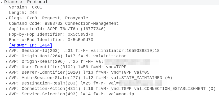
With this, the MME sends a Connection Management Request (CMR) towards the SCEF specified in the SCEF-ID returned by the HSS.
The Connection Management Request / Response
The MME now sends a Diameter T6a Connection Management Request to the SCEF in the Update Location Answer,
In it we have a Session-Id, which continues for the life of our NIDD session, the service-selection which contains our APN (In our case “non-ip”) and the User-Identifier AVP which contains the MSISDN and/or IMSI of the subscriber.
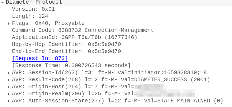
To accept this, the SCEF sends back a Connection-Management-Answer to confirm we’re all good to go:
At this point our SCEF now knows about the subscriber who’s just attached to our network, and correlates it with the APN and the session-ID.
On the S1 side the connection is confirmed and we’re ready to roll.
Mobile Originated Data Request / Response
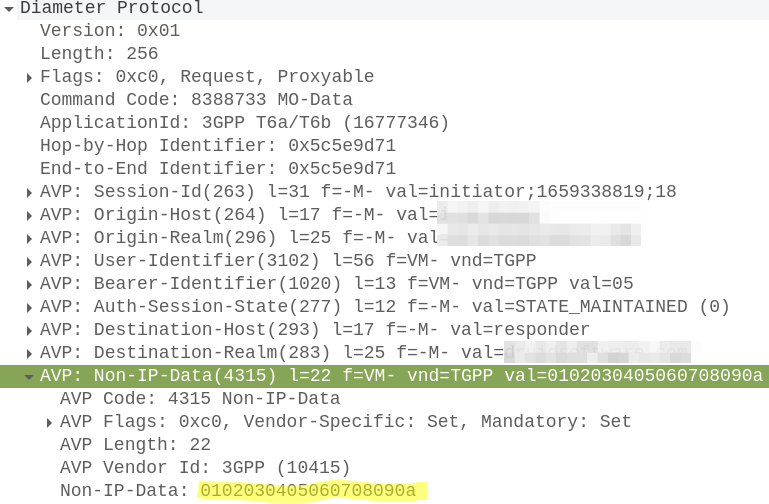
When the UE wants to send NIDD it’s carried in NAS messaging, so we see an Uplink NAS transport from the UE and inside the NAS payload itself is our HEX data.
Our MME grabs this out and sends it in the form of of a Mobile-Originated-Data-Request (MODR) to the SCEF, along with the same Session-ID that was setup earlier:
At this stage our Non-IP Data is exposed over the T8 RESTful API, which we won’t cover in this post.
PyHSS is our open source Home Subscriber Server, it’s written in Python, has a variety of different backends, and is highly perforate (We benchmark to 10K transactions per second) and infinitely scaleable.
In this post I’ll cover the basics of setting up PyHSS in your enviroment and getting some Diameter peers connected.
For starters, we’ll need a database (We’ll use MySQL for this demo) and an account on that database for a MySQL user.
So let’s get that rolling (I’m using Ubuntu 24.04):
sudo apt update
sudo apt install mysql-server
Next we’ll create the MySQL user for PyHSS to use:
CREATE USER 'pyhss_user'@'%' IDENTIFIED BY 'pyhss_password';
GRANT ALL PRIVILEGES ON *.* TO 'pyhss_user'@'%' WITH GRANT OPTION;
FLUSH PRIVILEGES;
We’ll also need Redis as well (PyHSS uses Redis for inter-service communications and for caching), so go ahead an install that for your distro:
sudo apt install redis-server
So that’s our prerequisites sorted, let’s clone the PyHSS repo:
And install the requirements with pip from the PyHSS repo:
pip3 install -r requirements.txt
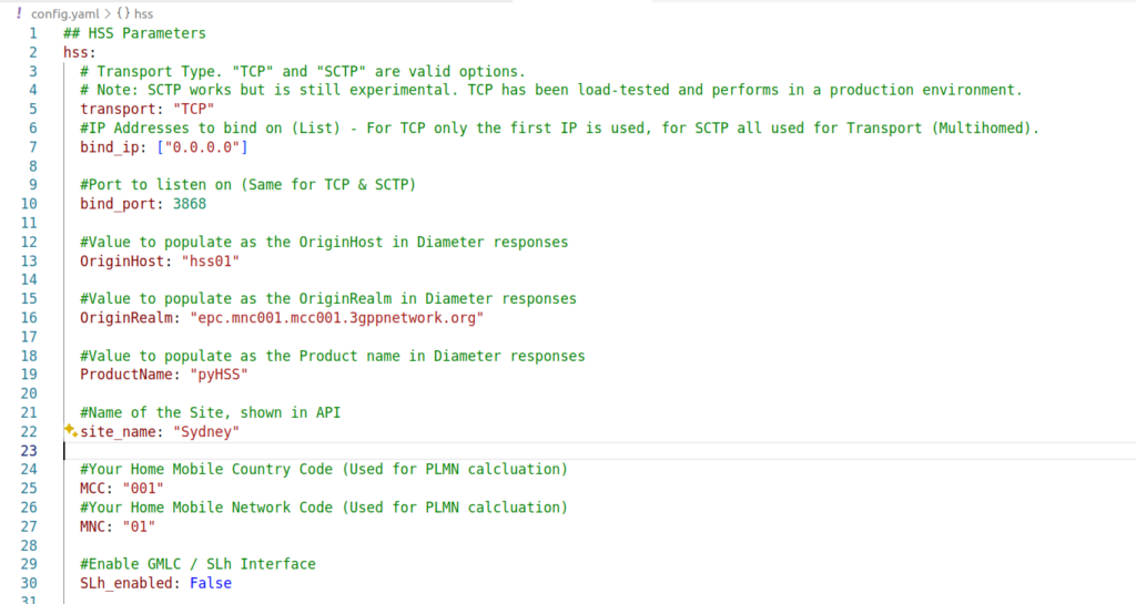
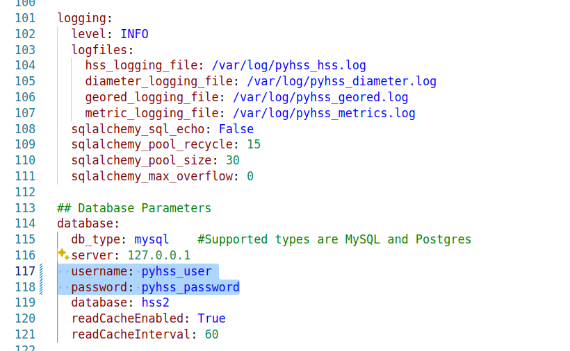
Next we’ll need to configure PyHSS, for that we update the config file (config.yaml) with the settings we want to use.
We’ll start by setting the bind_ip to a list of IPs you want to listen on, and your transport – We can use either TCP or SCTP.
For Diameter, we will set OriginHost and OriginRealm to match the Diameter hostname you want to use for this peer, and the Realm of your Diameter network.
Lastly we’ll need to set the database parameters, updating the database: section to populate your credentials, setting your username and password and the database to match your SQL installation we setup at the start.
With that done, we can start PyHSS, which we do using systemctl.
Because there’s multiple microservices that make up PyHSS, there’s multiple systemctl files use to run PyHSS as a service, they’re all in the /systemd folder.
The Equipment Identity Register (EIR) is a pretty handy function in 3GPP networks.
Via the Diameter based S13 interface, the MME, is able to query the EIR to ask if a given IMEI & IMSI combination should be allowed to attach.
This allows stolen / grey market / unauthorized devices (IMEIs) to be rejected from the network, the EIR can have a list of “bad” IMEIs that if seen will reject the request.
It also allows us to lock a SIM (IMSI) to a given device (IMEI) or type of device – We can use this for say a Fixed Wireless service, to lock the SIMs (IMSIs) to a range of modems (IMEI Prefixes).
Lastly it gives us insight and analytics into the devices used on the network, by mapping the IMEI to a device, we can say that IMEI 1234567890 is an Apple iPhone 12 Pro Max, or a Nokia Fastmile 5G-24W-A.
PyHSS supports all these capabilities, so let’s have a look at how we’d manage / access them.
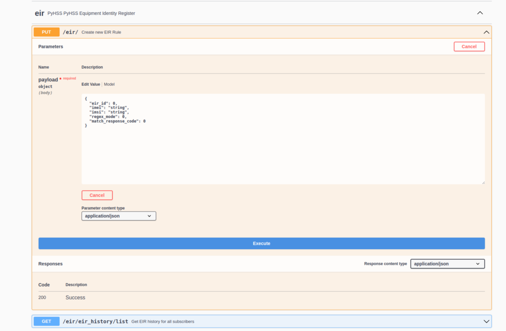
Setting up EIR Rules
These rules are set via the RESTful API in PyHSS.
The Equipment Identity Register built into PyHSS supports matching in one of two modes, set by regex_mode.
In Exact Mode (regex_mode: 0) matches are based on an exact matching IMEI, and matching the IMSI if set (If IMSI is set to nothing (”), then only the IMEI is evaluated).
Exact Mode is suited for IMEI/IMSI locking, to ensure a SIM is locked to a particular device, or to blacklist stolen devices.
Regex Mode (regex_mode: 1) matches based on Regex, this is suited for whitelisting IMEI prefixes for say, specific validated vendors.
The match_response_code maps to the Equipment-Status AVP output, so specified values are:
0 : ‘Whitelist’
1: ‘Blacklist’
2: ‘Greylist’
Some end to end examples of this provisioned into the API:
If the IMEI starts with 777 and the IMSI is 1234123412341234 then return 2 (Greylist).
No Match Behaviour
If there is no match from the backend, then the config parameter no_match_response dictates the response code returned (Blacklist/Whitelist/Greylist).
Mapping Type Allocation Codes (TACs) to IMEIs
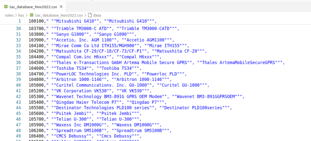
There are several data feeds of the Type Allocation Codes (TACs) which map a given IMEI prefix to a model number.
TAC database extract
Unfortunately, this data is not freely available, so we can’t bundle it with PyHSS, but if you have the IMEI Database, you can load it into PyHSS using Redis, to allow us to report on this data.
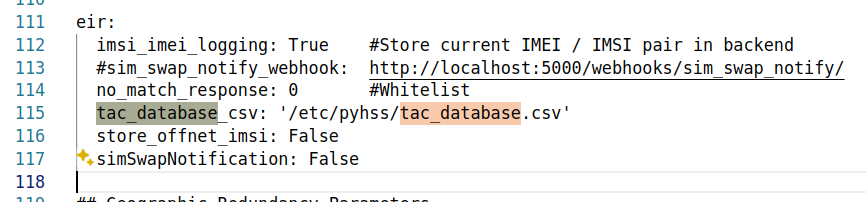
In your config.yaml you’ll just need to set the tac_database parameter, which will read the data on startup.
PyHSS YAML Config extract
Triggering on SIM Swap
If we keep track of the current IMSI/IMEI combination used for each SIM/Device, we can get notified every time it changes.
You might want to use this to trigger OTA provisioning or clear old data in your IMS.
For that we can use the sim_swap_notify_webhook in the config to send a HTTP POST to a given endpoint to inform it that a SIM is now in a different device.
We also have to have imsi_imei_logging set to true in the Config in order to log the history.
Reporting on IMEIs
We can also log/capture historical data about IMSI/IMEI combinations.
We use this from a customer support perspective to be able to see if a customer has recently changed phones, so if they call support, our staff can ask the customer about it to help troubleshoot.
“I can see you were connected previously on a Samsung Galaxy S22, but now you’re using a Nokia 3310, did the issues happen before you moved phones?”
This is super handy.
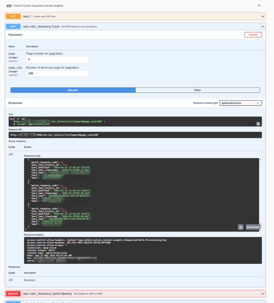
We can get a general log of IMSI vs IMEI like this:
Feed of IMSI vs IMEI along with a timestamp and the response that was sent back
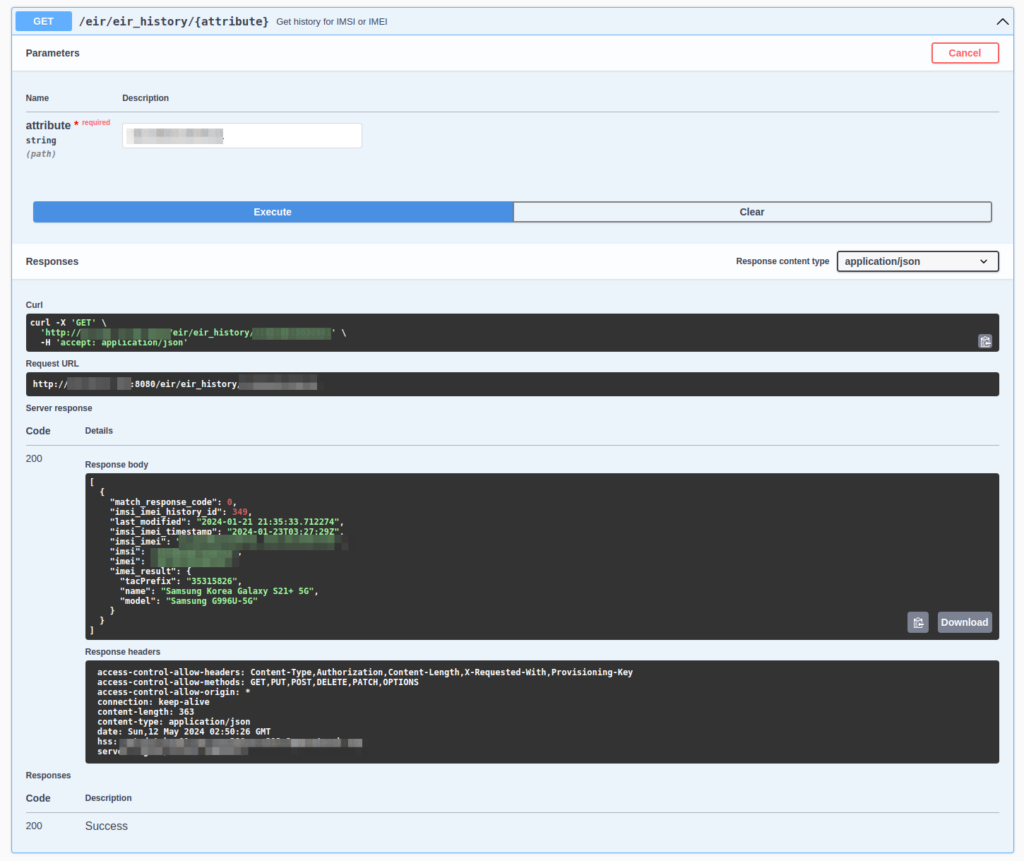
But what’s more useful is searching for a IMSI or an IMEI and then getting back a full list of devices / SIMs that have been used.
Searching for an IMSI I can see it’s only ever been used in this Samsung Galaxy
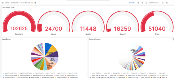
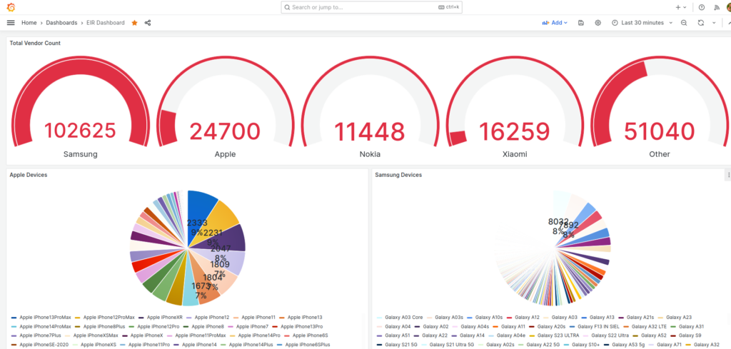
Lastly via Grafana we export all this data, which allows us to visualize this data and build dashboards showing the devices on the network.
Visualizing EIR Data in Grafana
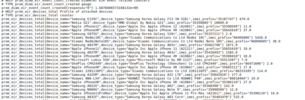
PyHSS includes a Promethues exporter, when it comes to prom_eir_devices_total it lists each seen Type Allocation Code / UE in the network, along with the number we’ve seen of each.
Raw it looks like this:
But visualized in Grafana we can get a dashboard to give us a breakdown per vendor:
How does one encode / interpret the value of this AVP / IE was the question I set out to answer.
TS 29.274 says:
For the encoding of this information element see 3GPP TS 32.298
TS 32.298 says:
The functional requirements for the Charging Characteristics as well as the profile and behaviour bits are further defined in normative Annex A of TS 32.251
TS 32.251 Annex A says:
The Charging Characteristics parameter consists of a string of 16 bits designated as Behaviours (B), freely defined by Operators, as shown in TS 32.298 [51]. Each bit corresponds to a specific charging behaviour which is defined on a per operator basis, configured within the PCN and pointed when bit is set to “1” value.
After a few circular references I found this is imported from 32.298.
Finally we find some solid answers hidden away in TS 132 215, under the Charging Characteristics Profile index.
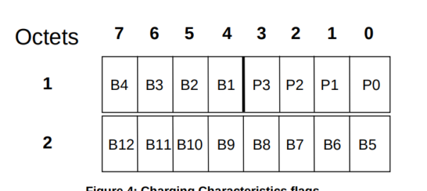
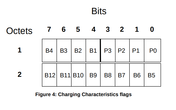
Charging Characteristics consists of a string of 16 bits designated as Profile (P) and Behaviour (B), shown in Figure 4. The first four bits (P) shall be used to select different charging trigger profiles, where each profile consists of the following trigger sets:
S-CDR: activate/deactivate CDRs, time limit, volume limit, maximum number of charging conditions, tariff times;
G-CDR: same as SGSN, plus maximum number of SGSN changes;
M-CDR: activate/deactivate CDRs, time limit, and maximum number of mobility changes;
SMS-MO-CDR: activate/deactivate CDRs;
SMS-MT-CDR: active/deactivate CDRs.
The Charging Characteristics field allows the operator to apply different kind of charging methods in the CDRs. A subscriber may have Charging Characteristics assigned to his subscription. These characteristics can be supplied by the HLR to the SGSN as part of the subscription information, and, upon activation of a PDP context, the SGSN forwards the charging characteristics to the GGSN on the Gn / Gp reference point according to the rules specified in Annex A of TS 32.251 [11].
This information can be used by the GSNs to activate CDR generation and control the closure of the CDR or the traffic volume containers (see clause 5.1.2.2.23) and is included in CDRs transmitted to nodes handling the CDRs via the Ga reference point. It can also be used in nodes handling the CDRs (e.g., the CGF or the billing system) to influence the CDR processing priority and routing.
These functions are accomplished by specifying the charging characteristics as sets of charging profiles and the expected behaviour associated with each profile.
The interpretations of the profiles and their associated behaviours can be different for each PLMN operator and are not subject to standardisation. In the present document only the charging characteristic formats and selection modes are specified.
The functional requirements for the Charging Characteristics as well as the profile and behaviour bits are further defined in normative Annex A of TS 32.251 [11], including the definitions of the trigger profiles associated with each CDR type.
The format of charging characteristics field is depicted in Figure 4. Px (x =0..3) refers to the Charging Characteristics Profile index. Bits classified with a “B” may be used by the operator for non-standardised behaviour (see Annex A of TS 32.251 [11]).
Right, well hopefully next time someone goes looking for this info you’ll find it a bit more easily than I did!
The S8 Home Routing approach for LTE Roaming works really well, as more and more operators are switching off their legacy circuit switched 2G/3G networks and shifting to LTE & VoLTE for roaming, we’re seeing more an more S8-HR deployments.
When LTE was being standardised in 2008, Local Breakout (LBO) and S8 Home Routing were both considered options for how roaming may look. Fast forward to today, and S8 Home routing is the only way roaming is done for modern deployments.
In light of this, there are some “best practices” in an “all S8 Home Routed” world, we’ve developed, that I thought I’d share.
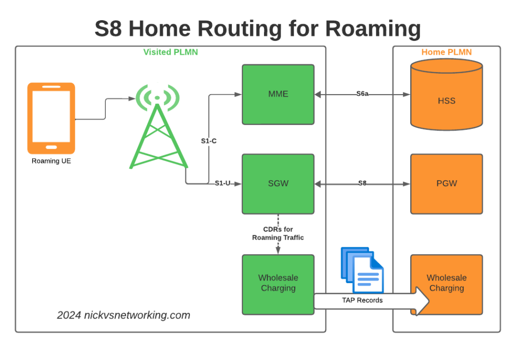
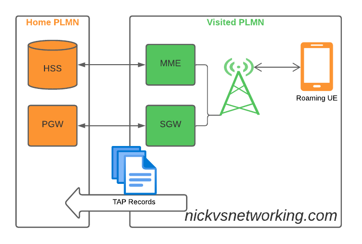
The Basics
When roaming, the SGW in the Visited Network, sends user traffic back to the PGW in the Home Network.
This means Online/Offline charging, IMS, PCRF, etc, is all done in the Home PLMN. As long as data packets can get from the SGW in the Visited PLMN to the PGW in the Home PLMN, and authentication flows from the Visited MME to the HSS in the Home PLMN, you’re golden.
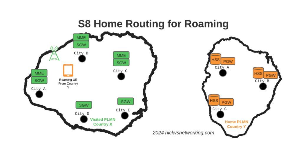
The Constraints
Of course real networks don’t look as simple as this, in reality a roaming scenario for a visited network has a lot more nodes, which need to be
Building Distributed Packet Core & IMS
Virtualization (VNF / CNF) has led operators away from “big iron” hardware for Packet Core & IMS nodes, towards software based solutions, which in turn offer a lot more flexibility.
Best practice for design of User Plane is to keep the the latency down, by bringing the user plane closer to the user (the idea of “Edge” UPFs in 5GC is a great example of this), and the move away from “big iron” in central locations for SGW and PGW nodes has been the trend for the past decade.
So to achieve these goals in the networks we build, we geographically distribute the core network.
This means we’ve got quite a few S-GW, P-GW, MME & HSS instances across the network. There’s some real advantages to this approach:
From a redundancy perspective this allows us to “spread the load” and build far more resilient networks. A network with 20 smaller HSS instances spread around the country, is far more resilient than 2 massive ones, regardless of how many power feeds or redundant disks it may have.
This allows us to be more resource efficient. MNOs have always provisioned excess capacity to cater for the loss of a node. If we have 2 MMEs serving a country, then each node has to have at least 50% capacity free, so if one MME were to fail, the other MME could handle the additional load it from it’s dead friend. This is costly for resources. Having 20 MMEs means each MME has to have 5% capacity free, to handle the loss of one MME in the pool.
It also forces our infrastructure teams to manage infrastructure “as cattle” rather than pets. These boxes don’t get names or lovingly crafted, they’re automatically spun up and destroyed without thinking about it.
For security, we only use internal IP addresses for the nodes in our packet core, this provides another layer of protection for the “crown jewels” of our network, so no one messing with BGP filtering can accidentally open the flood gates to our core, as one US operator learned leaving a GGSN open to the world leading to the private information for 100 million customers being leaked.
What this all adds to, is of course, the end user experience. For the end subscriber / customer, they get a better experience thanks to the reduced latency the connection provides, better uptime and faster call setup / SMS delivery, and less cost to deliver services.
I love this approach and could prothletise about it all day, but in a roaming context this presents some challenges.
The distributed networks we build are in a constant state of flux, new capacity is being provisioned in some areas, nodes things decommissioned in others, and our our core nodes are only reachable on internal IPs, so wouldn’t be reachable by roaming networks.
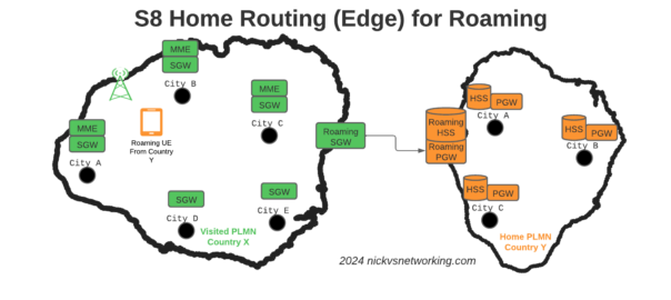
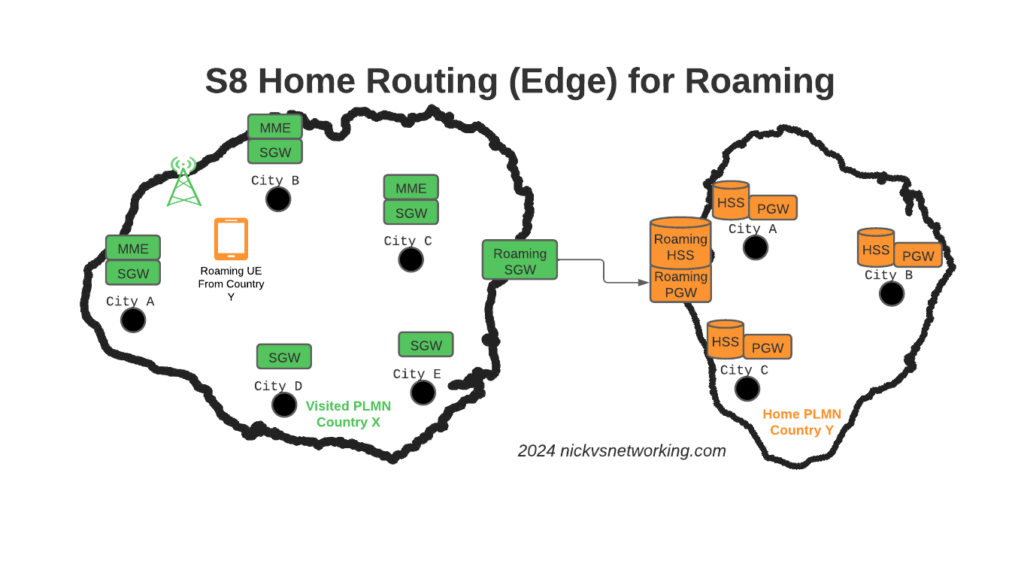
Our Distributed-Core Roaming Solution
To resolve this we’ve taken a novel approach, we’ve deployed a pair of S-GWs we call the “Roaming SGWs”, and a pair of P-GWs we call the “Roaming PGWs”, these do have public IPs, and are dedicated for use only by roaming traffic.
We really like this approach for a few reasons:
It allows us to be really flexible do what we want inside the network, without impacting roaming customers or operators who use our network for roaming. All the benefits I described from the distributed architectures can still be realised.
From a security standpoint, only these SGW/PGW pairs have public IPs, all the others are on internal IPs. This good for security – Our core network is the ‘crown jewels’ of the network and we only expose an edge to other providers. Even though IPX networks are supposed to be secure, one of the largest IPX providers had their systems breached for 5 years before it was detected, so being almost as distrustful of IPX traffic as Internet traffic is a good thing. This allows us to put these PGWs / SGWs at the “edge” of our network, and keep all our MMEs, as well as our on-net PGW and SGWs, on internal IPs, safe and secure inside our network.
For charging on the SGWs, we only need to worry about collecting CDRs from one set of SGWs (to go into the TAP files we use to bill the other operators), rather than running around hoovering up SGW CDRs from large numbers of Serving Gateways, which may get blown away and replaced without warning.
Of course, there is a latency angle to this, for international roaming, the traffic has to cross the sea / international borders to get to us. By putting it at the edge we’re seeing increased MOS on our calls, as the traffic is as close to the edge of the network as can be.
Caveat: Increased S11 Latency on Core Network sites over Satellite
This is probably not relevant to most operators, but some of our core network sites are fed only by satellite, and the move to this architecture shifted something: Rather than having latency on the S8 interface from the SGW to the PGW due to the satellite hop, we’ve got latency between the MME and the SGW due to the satellite hop.
It just shifts where in the chain the latency lies, but it did lead to us having to boost some timers in the MME and out of sequence deliver detection, on what had always been an internal interface previously.
Evolution to 5G Standalone Roaming
This approach aligns to the Home Routed options for 5G-SA roaming; UPF chaining means that the roaming traffic can still be routed, as seems to be the way the industry is going.
SA roaming is in its infancy, without widely deployed SA networks, we’re not going to see common roaming using SA for a good long while, but I’ll be curious to see if this approach becomes the de facto standard going forward.
Where to from here?
We’re pretty happy with this approach in the networks we’ve been building.
So far it’s made IREG testing easier as we’ve got two fixed points the IPX needs to hit (The DRAs and the SGWs) rather than a wide range of networks.
Operators with a vast number of APNs they need to drop into different VRFs may have to do some traffic engineering here – Our operations are generally pretty flat, but I can see where this may present some challenges for established operators shifting their traffic.
I’d be keen to hear if other operators are taking this approach and if they’ve run into any issues, or any issues others can see in this, feel free to drop a comment below.
SGs-AP which is used for CSFB & SMS doesn’t span network borders (you can’t roam with SGs-AP), and with SMSoIP out of the question, that gave us the option of MAP or Diameter, so we picked Diameter.
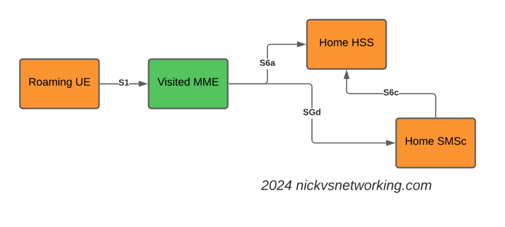
This introduces the S6c and SGd Diameter interfaces, in the diagrams below Orange is the Home Network (HPMN) and the Green is the Visited Network (VPMN).
The S6c interface is used between the SMSc and the HSS, in order to retrieve the routing information. This like the SRI-for-SM in MAP.
The SGd interface is used between the MME serving the UE and the SMSc, and is used for actual delivery of the MO/MT messages.
I haven’t shown the Diameter Routing Agents in these diagrams, but in reality there would be a DRA on the VPLMN and a DRA on the HPMN, and probably a DRA in the IPX between them too.
The Attach
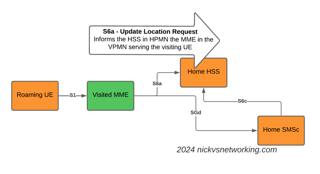
The attach looks like a regular roaming attach, the MME in the Visited PMN sends an Update Location Request to the HSS, so the HSS knows the MME that is serving the subscriber.
S6a Update Location Request to indicate the MME serving the Subscriber
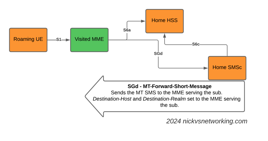
The Mobile Terminated SMS Flow
Now we introduce the S6c interface and the SGd interfaces.
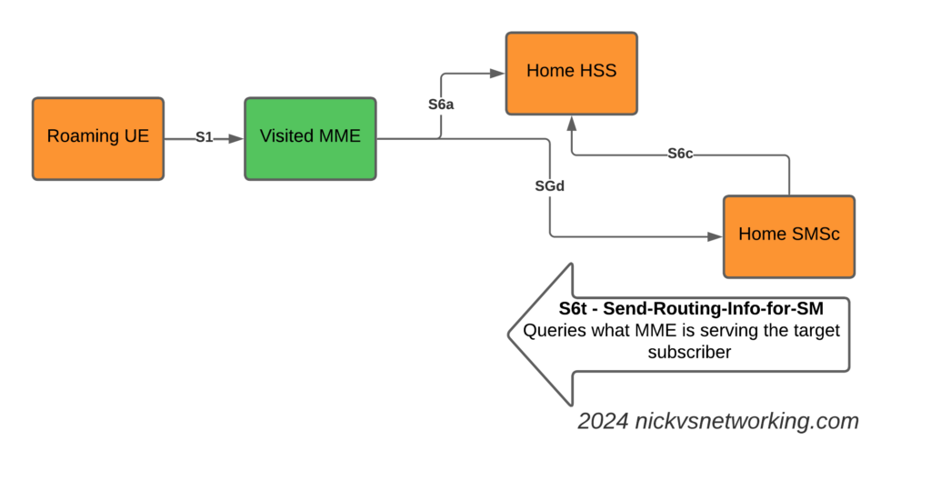
When the Home SMSc has a message to send to the subscriber (Mobile Terminated SMS) it runs a the Send-Routing-Info-for-SM-Request (SRR) dialog to the HSS.
The Send-Routing-Info-for-SM-Answer (SRA) back from the HSS contains the info on the MME Diameter Host name and Diameter Realm serving the subscriber.
S6t – Send-Routing-Info-for-SM request to get the MME serving the subscriber
With this info, we can now craft a Diameter Request that will get sent to the MME serving the subscriber, containing the SMS PDU to send to the UE.
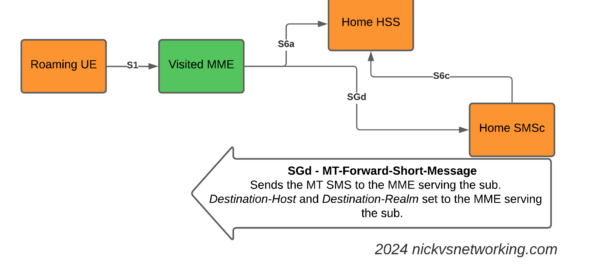
SGd MT-Forward-Short-Message to deliver Mobile Terminated SMS to the serving MME
We make sure it’s sent to the correct MME by setting the Destination-Host and Destination-Realm in the Diameter request.
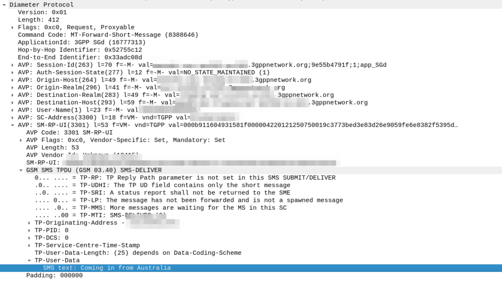
Here’s how the request looks from the SMSc towards our DRA:
As you can see the Destination Realm and Destination-Host is set, as is the User-Name set to the IMSI of the UE we want to send the message to.
And down the bottom you can see the SMS-TPDU, the same as it’s been all the way back since GSM days.
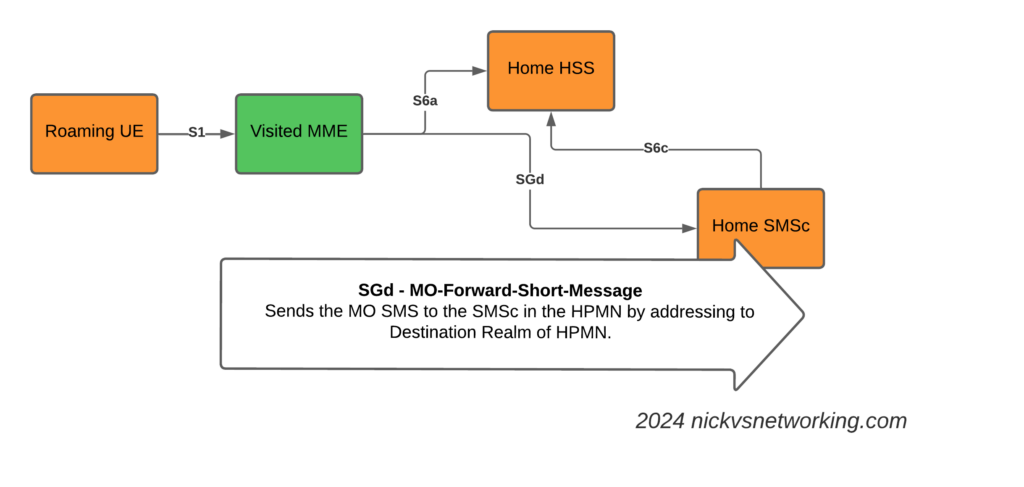
The Mobile Originated SMS Flow
The Mobile Originated flow is even simpler, because we don’t need to look up where to route it to.
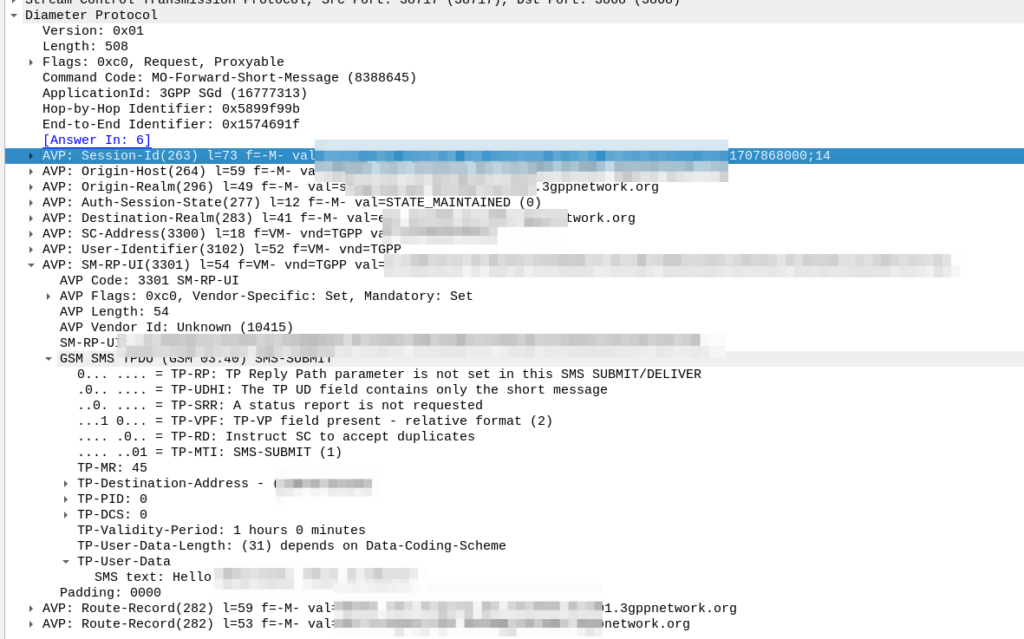
The MME receives the MO SMS from the UE, and shoves it into a Diameter message with Application ID set to SGd and Destination-Realm set to the HPMN Realm.
When the message reaches the DRA in the HPMN it forwards the request to an SMSc and then the Home SMSc has the message ready to roll.
Even before 5G was released, the arms race to claim the “fastest” speeds on LTE, NSA and SA networks has continued, with pretty much every operator claiming a “first” or “fastest”.
I myself have the fastest 5G network available* but I thought I’d look at how big the values are we can put in for speed, these are the Maximum Bitrate Values (like AMBR) we can set on an APN/DNN, or on a Charging Rule.
*Measurement is of the fastest 5G network in an eastward facing office, operated by a person named Nick, in a town in Australia. Other networks operated by people other than those named Nick in eastward facing office outside of Australia were not compared.
The answer for Release 8 LTE is 4294967294 bytes per second, aka 4295 Mbps 4.295 Gbps.
Not bad, but why this number?
The Max-Requested-Bandwidth-DL AVP tells the PGW the max throughput allowed in bits per second. It’s a Unsigned32 so max value is 4294967294, hence the value.
But come release 15 some bright spark thought we may in the not to distant future break this barrier, so how do we go above this?
The answer was to bolt on another AVP – the “Extended-Max-Requested-BW-DL” AVP ( 554 ) was introduced, you might think that means the max speed now becomes 2x 4.295 Gbps but that’s not quite right – The units was shifted.
This AVP isn’t measuring bits per second it’s measuring kilobits per second.
So the standard Max-Requested-Bandwidth-DL AVP gives us 4.3 Gbps, while the Extended-Max-Requested-Bandwidth gives us a 4,295 Gbps.
We add the Extended-Max-Requested-Bandwidth AVP (4295 Gbps) onto the Max-Requested Bandwidth AVP (4.3 Gbps) giving us a total of 4,4299.3 Gbps.
We recently added support in PyHSS for fixed line SIP subscribers to attach to the IMS.
Traditional telecom operators are finding their fixed line network to be a bit of a money pit, something they’re required to keep operating to meet regulatory obligations, but the switches are sitting idle 99% of the time. As such we’re seeing more and more operators move fixed line subs onto their IMS.
This new feature means we can use PyHSS to serve as the brains for a fixed network, as well as for mobile, but there’s one catch – How we authenticate subscribers changes.
Most banks of line cards in a legacy telecom switches, or IP Phones, don’t have SIM slots to allow us to authenticate, so instead we’re forced to fallback to what they do support.
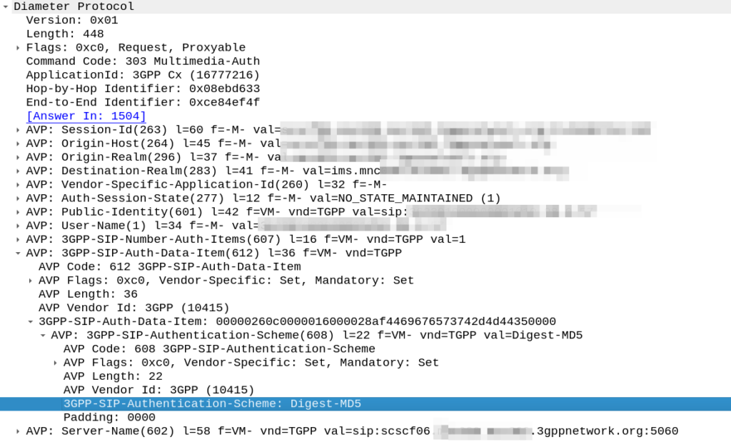
Unfortunately for the most part, what is supported by these IP phones or telecom switches is SIP MD5 Digest Authentication.
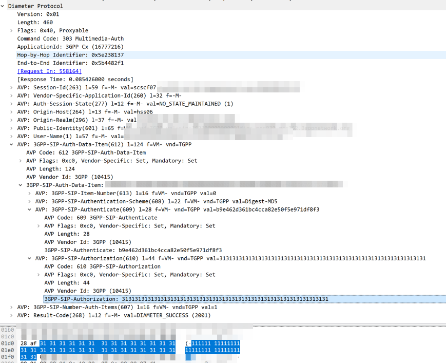
The Nonce is generated by the HSS and put into the Multimedia-Authentication-Answer, along with the subscriber’s password and sent in the clear to the S-CSCF.
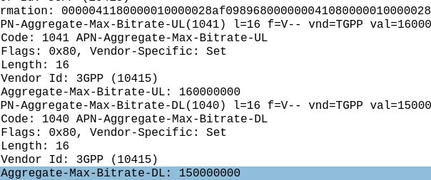
The HSS then generates the the Multimedia-Auth Answer, it generates a nonce (in the 3GPP-SIP-Authenticate / 609 AVP) and sends the Subscriber’s password in the 3GPP-SIP-Authorization (610) AVP in response back to the S-CSCF.
I would have thought a better option would be for the HSS to generate the Nonce and Digest, and then the S-CSCF to just send the Nonce to the Sub and compare the returned Digest from the Sub against the expected Digest from the HSS, but it would limit flexibility (realm adaptation, etc) I guess.
The UE/UA (I guess it’s a UA in this context as it’s not a mobile) then generates its own Digest from the Nonce and sends it back to the S-CSCF via the P-CSCF.
The S-CSCF compares the received Digest response against the one it generated, and if the two match, the sub is authenticated and allowed to attach onto the network.
If you’ve ever worked in roaming, you’ll probably have had the misfortune of dealing with Transferred Account Procedures aka TAP files.
It’s used for billing a 2G GSM call right up to 5G data usage, if you use a service while roaming, somewhere in the world there’s a TAP file with your usage in it.
A brief history of TAP
TAP was originally specified by the GSMA in 1991 as a standard CDR interchange format between operators, for use in roaming scenarios.
Notice I said GSMA – Not 3GPP – This means there’s no 3GPP TS docs for this, it’s defined by the industry lobby group’s members, rather than the standards body.
So what does this actually mean? Well, if you’re MNO A and a customer from MNO B roams into your network, all the calls, SMS and data consumed by the roaming subscriber from MNO B will need to be billed to MNO B, by you, MNO A.
If a network operator wants to get paid for traffic used on their network by roaming subscribers, they’d better send out a TAP file to the roamer’s home network.
TAP is the file format generated my MNO A and sent to MNO B, containing all the usage charges that subscribers from MNO B have racked up while roaming into your network.
These are broken down into “Transactions” (CDRs), for events like making a call, connecting a PDN session and consuming data, or sending a text.
In the beginning of time, GSM provided only voice calling service. This meant that the only services a subscriber could consume while roaming was just making/receiving voice calls which were billed at the end of each month. – This meant billing was equally simple, every so often the visisted network would send the TAP files for the voice calls made by subscribers visited other networks, to the home networks, which would markup those charges, and add them onto the monthly invoice for each subscriber who was roaming.
But of course today, calling accounts for a tiny amount of usage on the network, but this happened gradually while passing through the introduction of SMS, CAMEL services, prepaid services, mobile data, etc. For all these services that could be offered, the TAP format had to evolve to handle each of these scenarios.
As we move towards a flat IP architecture, where voice calls and SMS sent while roaming are just data, TAP files for 4G and 5G networks only need to show data transactions, so the call objects, CAMEL parameters and SMS objects are all falling by the wayside.
What’s inside a TAP File
TAP uses the most beloved of formats – ASN1 to encode the data. This means it is strictly formatted and rigidly specified.
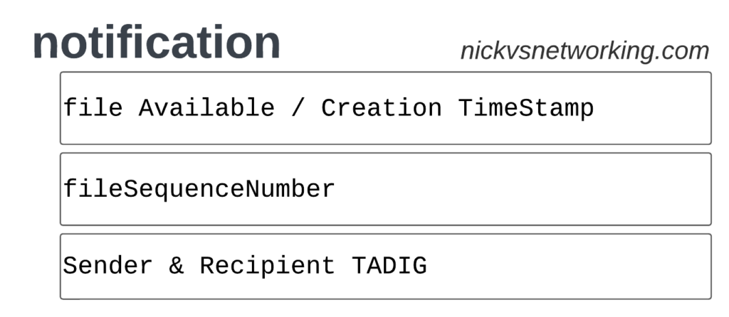
Each file contains a Sequence Number which is a monotonically increasing number, which allows the receiver to know if any files have been missed between the file that’s being currently parsed, an the previous file.
They also have a recipient and sender TADIG code, which is a code allocated by GSMA that uniquely identifies the sender and the recipient of the file.
The TAP records exist in one of two common format, Notification Records and transferBatch records.
These files are exchanged between operators, in practice this means “Dumped on an FTP server as agreed between the two”.
TAP Notification Records
Notifications are the simplest of TAP records and are used when there aren’t any CDRs for roaming events during the time period the TAP file covers.
These are essentially blank TAP files generated by the visited network to let the home network know it’s still there, but there are no roaming subs consuming services in that period.
Notification files are really simple, let’s take a look as one shown as JSON:
When we have services to bill and records to charge, that’s when instead we generate a transferBatch record.
It looks something like this:
There’s a lot going on in here, so let’s break it down section by section.
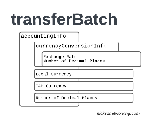
accountingInfo
The accountingInfo section specifies the currency, exchange rate parameters.
Keep in mind a TAP record generated by an operator in the US, would use USD, while the receiver of the file may be a European MNO dealing in EUR.
This gets even more complicated if you’re dealing with more obscure currencies where an intermediary currency is used, that’s where we bring in SDRs (“Special Drawing Right”) that map to the dollar value to be charged, kinda – the roaming agreement defines how many SDRs are in a dollar, in the example below we’re not using any, but you do see it.
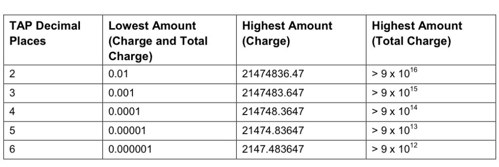
When it comes to numbers and decimal places, TAP doesn’t exactly make it easy.
Significant Digits are defined by counting the first number before the decimal point and all the numbers to the right of the decimal point, so for example the number 1.234 would be 4 significant digits (1 digit before the decimal point and 3 digits after it).
Decimal Places are not actually supported for the Value fields in the TAP file. This is tricky because especially today when roaming tariffs are quite low, these values can be quite small, and we need to represent them as an integer number. TAP defines decimal places as the number of digits after the decimal place.
When it comes to the maximum number of decimal places, this actually impacts the maximum number we can store in the field – as ASN1 strictly enforce what we put in it.
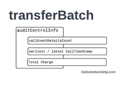
The auditControlInfo section contains the number of CDRs (callEventDetailsCount) contained in the TAP file, the timestamp of the first and last CDR in the file, the total charge and any tax charged.
All of the currency information was provided in the accountingInfo so this is just giving us our totals.
A CDR has 30 days from the time it was generated / service consumed by the roamer, to be baked into a TAP file. After this we can no longer charge for it, so it’s important that the earliestCallTimeStamp is not more than 30 days before the fileCreationTimeStamp seen in batchControlInfo.
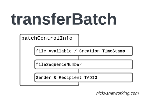
batchControlInfo
The batchControlInfo section specifies the time the TAP file became available for transfer, the time the file was created (usually the same), the sequence number and the sender / recipient TADIG codes.
As mentioned earlier, we track sequence number so the receiver can know if a TAP file has been missed; for example if you’ve got TAP file 1 and TAP file 3 comes in, you can determine you’ve missed TAP file 2.
Now we’re getting to the meat & potatoes of our TAP record, the CDRs themselves.
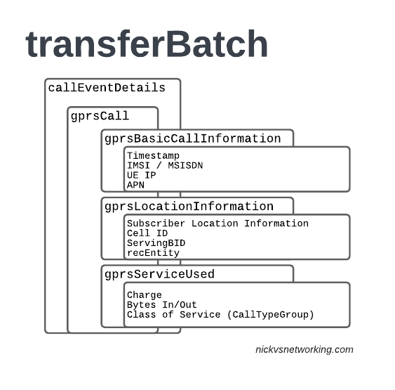
In LTE networks these are just records of data consumption, so let’s take a look inside the gprsCall records under callEventDetails:
In the gprsBasicCallInformation we’ve got as the name suggests the basic info about the data usage event. The time when the session started, the charging ID, the IMSI and the MSISDN of the subscriber to charge, along with their IP and the APN used.
Next up we have the gprsLocationInformation – rates and tariffs may be set based on the location of the subscriber, so we need to identify the area the sub was using the services to select correct tariff / rate for traffic in this destination.
The recEntity is the index number of the SGW / PGW used for the transaction (more on that later).
Next we have the gprsServiceUsed which, again as the name suggests, details the services used and the charge.
chargeDetailList contains the charged data (Made up of dataVolumeIncoming + dataVolumeOutgoing) and the cost.
The chargeableUnits indicates the actual data consumed, however most roaming agreements will standardise on some level of rounding, for example rounding up to the nearest Kilobyte (1024 bytes), so while a sub may consume 1025 bytes of data, they’d be billed for 2045 bytes of data. The data consumed is indicated in the chargeableUnits which indicates how much data was actually consumed, before any rounding policies where applied, while the amount that is actually charged (When taking into account rounding policies) isindicated inside Charged Units.
In the example below data usage is rounded up to the nearest 1024 bytes, 134390 bytes rounds up to the nearest 1024 gives you 135168 bytes.
As this is data we’re talking bytes, but not all bytes are created equal!
VoLTE traffic, using a QCI1 bearer is more valuable than QCI 9 cat videos, and TAP records take this into account in the Call Type Groups, each of which has a different price – Call Type Level 1 indicates the type of traffic, for S8 Home Routed LTE Traffic this is 10 (HGGSN/HP-GW), while Call Type Level 2 indicates the type of traffic as mapped to QCI values:
So Call Type Level 2 set to 20 indicates that this is “20 Unspecified/default LTE QCIs”, and Call Type Level 3 can be set to any value based on a defined inter-operator tariff.
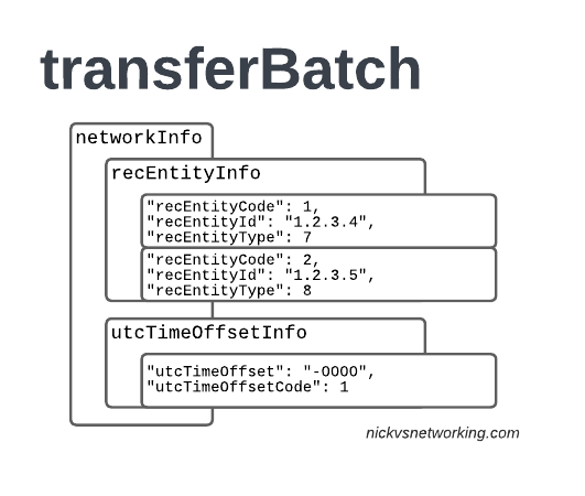
recEntityType 7 means a PGW and contains the IP of the PGW in the Home PLMN, while recEntityType 8 means SGW and is the SGW in the Visited PLMN.
So this means if we reference recEntityCode 2 in a gprsCall, that we’re referring to an SGW at 1.2.3.5.
Lastly also got the utcTimeOffsetInfo to indicate the timezones used and assign a unique code to it.
Using the Records
We as humans? These records aren’t meant for us.
They’re designed to be generated by the Visited PLMN and sent to to the home PLMN, which ingests it and pays the amount specified in the time agreed.
Generally this is an FTP server that the TAP records get dumped into, and an automated bank transfer job based on the totals for the TAP records.
Testing of the TAP records is called “TADIG Testing” and it’s something we’ll go into another day, but in essence it’s validating that the output and contents of the files meet what both operators think is the contract pricing and specifications.
So that’s it! That’s what’s in a TAP record, what it does and how we use it!
GSMA are introducing BCE – Billing & Charging Evolution, a new standard, designed to last for the next 30+ years like TAP has. It’s still in its early days, but that’s the direction the GSMA has indicated it would like to go.