The other side of the SCTP connection didn’t like my SCTP parameters.
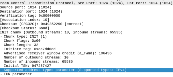
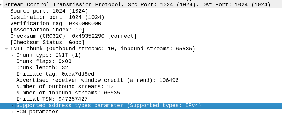
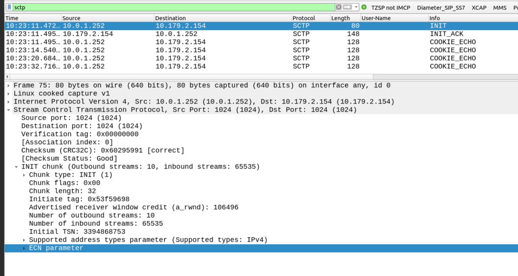
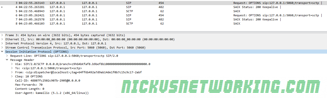
My SCTP INIT looked like this:
By default, Linux includes support for the ECN and SupportedAddressTypes parameters in the SCTP INIT.
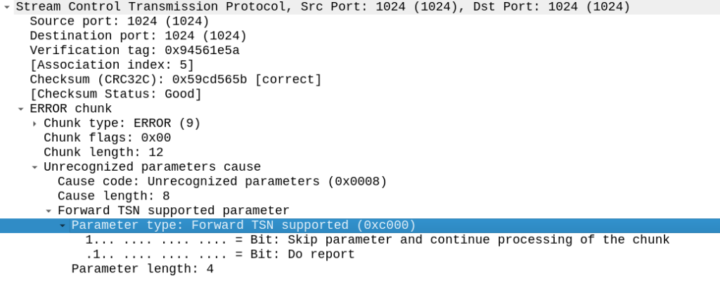
But the other side did not like this, it sent back an ERROR stating that:
Okay, apparently it doesn’t like the fact that we support Forward Transmission Sequence Numbers – So how to turn it off?
I’m using P1Sec’s PySCTP library to interact with the SCTP stack, and I couldn’t find any referneces to this in the code, but then I rememberd that PySCTP is just a wrapper for libsctp so I should be able to control it from there.
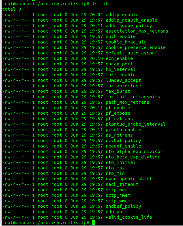
Inside /proc/sys/net/sctp we can see all the parameters we can control.
To disable the Forward TSN I need to disable the feature that controls it – Forward Transmission Sequence numbers are introduced in the Partial Reliability Extension (RFC 3758). So it was just a matter of disabling that with:
But if you really want to get the most bang for your buck, you’ll need to tune your SCTP parameters to match the network conditions.
While tuning the parameters per-association would be time consuming, most SCTP stacks allow you to set templates for SCTP parameters, for example you would have a different set of parameters for the SCTP stacks inside your network, compared to SCTP stacks for say a roaming scenario or across microwave links.
IETF kindly provides a table with their recommended starting values for SCTP parameter tuning:
But by adjusting the Max Retrans and Retransmission Timeout (RTO) values, we can detect failures on the network more quickly, and reduce the number of packets we’ll loose should we have a failure.
We begin with the engineered round-trip time (RTT) – that is made up of the time it takes to traverse the link, processing time for the remote SCTP stack and time for the response to traverse the link again. For the examples below we’ll take an imaginary engineered RTT of 200ms.
RTO.min is the minimum retransmission timeout. If this value is set too low then before the other side has had time to receive the request, process it and send a response, we’ve already retransmitted it.
This should be set to the round trip delay plus processing needed to send and acknowledge a packet plus some allowance for variability due to jitter; a value of 1.15 times the Engineered RTT is often chosen
So for us, 200 * 1.15 = 230ms RTO.min value.
RTO.max is the maximum amount of time we should wait before transmitting a request. Typically three times the Engineered RTT.
So for us, 200 * 3 = 600ms RTO.min value.
Path.Max.Retransmissions is the maximum number of retransmissions to be sent down a path before the path is considered to be failed. For example if we loose a transmission path on a multi-homed server, how many retransmissions along that path should we send until we consider it to be down?
Values set are dependant on if you’re multi-homing or not (you can be more picky if you are) and the level of acceptable packet loss in your transmission link.
Typical values are 4 Retransmissions (per destination address) for a Single-Homed association, and 2 Retransmissions (per destination address) for a Multi-Homed association.
Association.Max.Retransmissions is the maximum number of retransmissions for an association. If a transmission link in a multi-homed SCTP scenario were to go down, we would pass the Path.Max.Retransmissions value and the SCTP stack would stop sending traffic out that path, and try another, but what if the remote side is down? In that scenario all our paths would fail, so we need another counter – Path.Max.Retransmissions to count the total number of retransmissions to an association / destination. When the Association.Max.Retransmissions is reached the association is considered down.
In practice this value would be the number of paths, multiplied by the Path.Max.Retransmissions.
One of the key advantages of SCTP over TCP is the support for Multihoming,
From an application perspective, this enables one “socket”, to be shared across multiple IP Addresses, allowing multiple IP paths and physical NICs.
Through multihoming we can protect against failures in IP Routing and physical links, from a transport layer protocol.
So let’s take a look at how this actually works,
For starters there’s a few ways multihoming can be implemented, ideally we have multiple IPs on both ends (“client” and “server”), but this isn’t always achievable, so SCTP supports partial multi-homing, where for example the client has only one IP but can contact the server on multiple IP Addresses, and visa-versa.
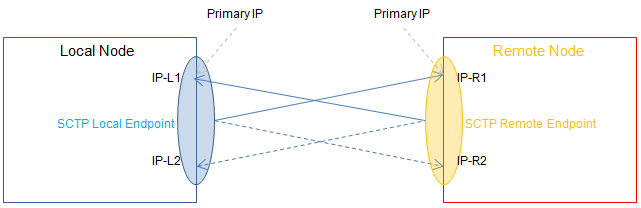
The below image (Courtesy of Wikimedia) shows the ideal scenario, where both the client and the server have multiple IPs they can be reached on.
This would mean a failure of any one of the IP Addresses or the routing between them, would see the other secondary IP Addresses used for Transport, and the application not even necessarily aware of the interruption to the primary IP Path.
The Process
For starters, our SCTP Client/Server will each need to be aware of the IPs that can be used,
This is advertised in the INIT message, sent by the “client” to a “server” when the SCTP session is established.
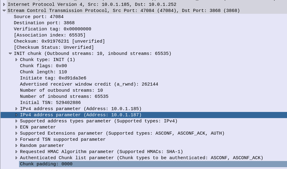
SCTP INIT sent by the client at 10.0.1.185, but advertising two IPs
In the above screenshot we can see the two IPs for SCTP to use, the primary IP is the first one (10.0.1.185) and also the from IP, and there is just one additional IP (10.0.1.187) although there could be more.
In a production environment you’d want to ensure each of your IPs is in a different subnet, with different paths, hardware and routes.
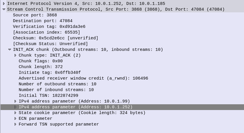
So the INIT is then responded to by the client with an INIT_ACK, and this time the server advertises it’s IP addresses, the primary IP is the From IP address (10.0.1.252) and there is just one additional IP of 10.0.1.99,
SCTP INIT ACK showing Server’s Multi-homed IP Options
Next up we have the cookie exchange, which is used to protect against synchronization attacks, and then our SCTP session is up.
So what happens at this point? How do we know if a path is up and working?
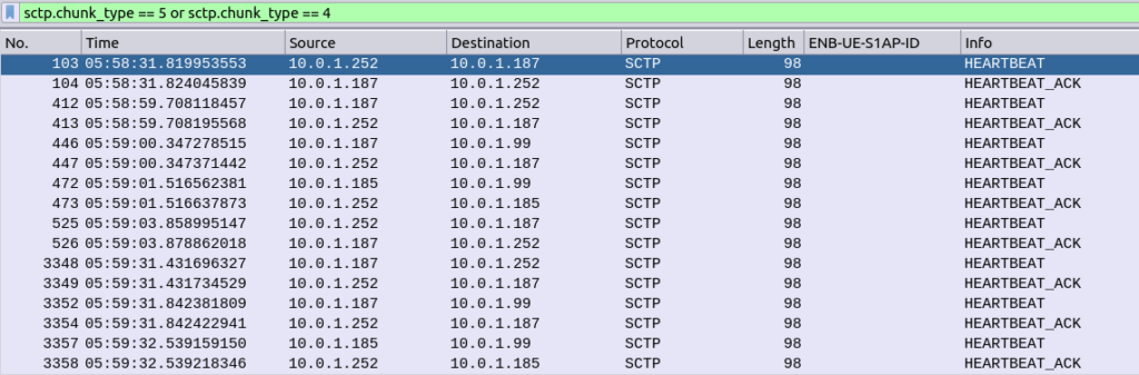
Well the answer is heartbeat messages,
Sent from each of the IPs on the client to each of the IPs on the server, to make sure that there’s a path from every IP, to every other IP.
SCTP Heartbeats from each local IP to each remote IP
This means the SCTP stacks knows if a path fails, for example if the route to IP 10.0.1.252 on the server were to fail, the SCTP stack knows it has another option, 10.0.1.99, which it’s been monitoring.
So that’s multi-homed SCTP in action – While a lot of work has historically been done with LACP for aggregating multiple NICs together, and VRRP for ensuring a host is alive, SCTP handles this in a clean and efficient way.
I’ve attached a PCAP showing multi-homing on a Diameter S6a (HSS) interface between an MME and a HSS.
If you’d like to write your own software using SCTP there’s a fantastic SCTP sockets library from P1 Security that makes this easy as any other socket programming.
Take a look at the super simple client-server I made:
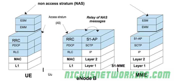
The LTE architecture compartmentalises the roles in the mobile network.
For example the eNB concentrates on radio connection management, while the MME focuses on security and mobility.
Non Access Stratum (NAS) messages are exchanged between the terminal and the MME.
Access Stratum (AS) messages are exchanged over the air between the UE and the eNB. It contains all the radio related information.
The eNB must map the NAS messages from an MME to a LCID and RNTI and transmit them over the air, and vice-versa. The eNB forwards this data without ever analyzing it.
To handle this load the requirements of each subscriber for the MME must be as minimal and simple as possible so as to scale easily.
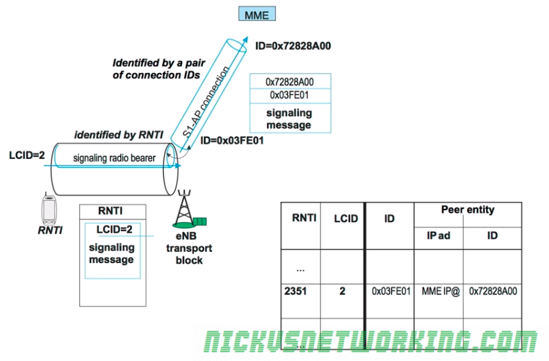
For each UE in the network a connection is setup between the UE and the MME.
This is done over the S1-AP’s Control Plane interface (sometimes calls S1-Control Plane or S1-CP) which carries control plane data to & from the UE via the eNB to the MME.
S1-CP is connection-oriented, meaning each UE has it’s own connection to the MME, so there are as many S1-CP connections to the MME as UE’s connected.
Each of these S1-CP connections is identified by a pair of unique connection IDs. The eNB keeps track of the connection IDs for each UE connected and hands this information off each time the UE moves to a different eNB.
The eNB keeps a lookup table between the RNTI of the UE and the LCID – the Logical Channel Identifier. This means that the eNB knows the sent and received ID of the S1-CP connection for each UE, and is able to translate that into the RNTI and LCID used to send the data over the air interface to the UE.
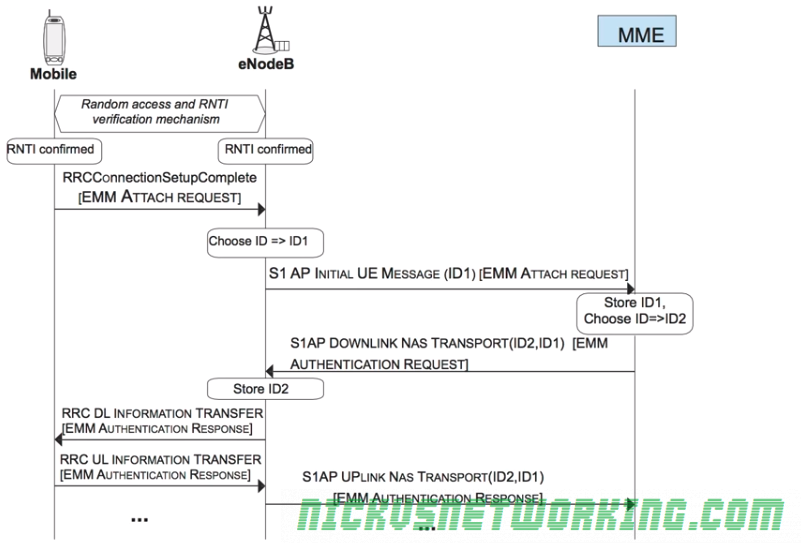
Once the RNTI is confirmed by both the eNB and the UE, a EMM Attach Request, which is put into an RRC Message called RRCConnectionSetupComplete.
The eNB must next choose a serving MME for this UE. It picks one based on it’s defined logic, and sends a S1-AP Intial UE Message (EMM Attach Request) to the MME along with the eNB’s connection identity assigned for this connection.
The MME stores the connection identity assigned by the eNB and chooses it’s own connection identity for it’s side, and sends back an S1AP Downlink NAS Transport response with both connection identities and the response for the attach request (This will be an EMM Authentication Request).
The eNB then stores the connection identity pair and the associated RNTI and LCID for the UE, and forwards the EMM Authentication Request to the RNTI of the UE via RRC.
The UE will pass the authentication challenge input parameters to the USIM which will generate a response. The UE will send the output of this response in a EMM Authentication Responseto the eNB, which will look at the RNTI and LCID received and consult the table to find the Connection Identifiers and IP of the serving MME for this UE.
Sometimes standards are created that are superior in some scenarios, and just don’t get enough love.
To me Stream Control Transmission Protocol (SCTP) is one of those, and it’s really under-utilised in Voice.
Defined by the SIGTRAN working group in 2000 while working to transport SS7 over IP, SCTP takes all the benefits of TCP, mixes in some of the benefits of UDP (No head of line blocking) and mutihoming support, and you’ve got yourself a humdinger of a Transmission Protocol.
Advantages
Reliable Transmission
Like TCP, SCTP includes a reliable transmission mechanism that ensures packets are delivered and retries if they’re not.
Multi Homing
SCTP’s multi homing allows a single connection to be split across multiple paths. This means if you had two paths between Melbourne and Sydney, you could be sending data down both simultaneously.
This means a loss of one transmission path results in the data being sent down another available transmission path.
If you’re doing this using TCP you’d have to wait for the TCP session to expire, BGP to update and then try again. Not so with SCTP.
No Head of Line Blocking
An error / discard with a packet in a TCP stream requires a re-transmission, blocking anything else in that stream from getting through until the error/discarded packet is sorted out. This is referred to as “head of line blocking” and is generally avoided by switching to UDP but that looses the reliability.
4 Way Handshake
Compared to TCP’s 3-way handshake which is susceptible to SYN flooding.
Deployment
If you’ve got a private network, chances are it can support SCTP.
There’s built in SCTP support in almost all Linux kernels since 2002, Cisco iOS and VxWorks all have support, and there’s 3rd party drivers for OSX and Windows.
SCTP is deployed in 3GPP’s LTE / EPC protocol stack for communication over S1-AP and X2 interfaces, meaning if you’ve got a LTE enabled mobile you’re currently using it, not that you’d see the packets.
You’ll find SCTP in SIGTRAN implementations and some TDM-IP gateways, Media Gateways, protocol converters etc, but it’s not widely deployed outside of this.