In the S1-SETUP-RESPONSE and MME-CONFIGURATION-UPDATE there’s a RelativeMMECapacity (87) IE,
So what does it do?
Most eNBs support connections to multiple MMEs, for redundancy and scalability.
By returning a value from 0 to 255 the MME is able to indicate it’s available capacity to the eNB.
The eNB uses this information to determine which MME to dispatch to, for example:
MME Pool
Relative Capacity
mme001.example.com
20/255
mme002.example.com
230/255
Example MME Pooling table
The eNB with the table above would likely dispatch any incoming traffic to MME002 as MME001 has very little at capacity.
If the capacity was at 1/255 then the MME would very rarely be used.
The exact mechanism for how the MME sets it’s relative capacity is up to the MME implementer, and may vary from MME to MME, but many MMEs support setting a base capacity (for example a less powerful MME you may want to set the relative capacity to make it look more utilised).
I looked to 3GPP to find what the spec says:
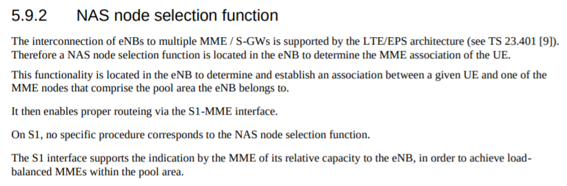
On S1, no specific procedure corresponds to the NAS node selection function. The S1 interface supports the indication by the MME of its relative capacity to the eNB, in order to achieve loadbalanced MMEs within the pool area.
3GPP TS 36.410 – 5.9.2 NAS node selection function
There’s a lot of layers of signalling in the LTE / EUTRAN attach procedure, but let’s take a look at the UE attach procedure from the Network Perspective.
We won’t touch on the air interface / Uu side of things, just the EPC side of the signaling.
To make life a bit easier I’ve put different signalling messages in different coloured headings:
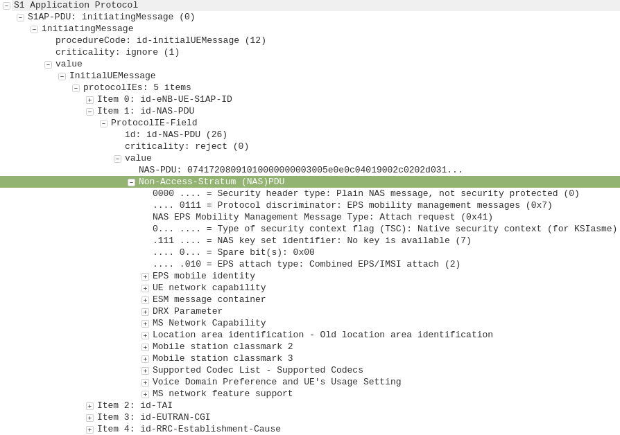
After a UE establishes a connection with a cell, the first step involved in the attach process is for the UE / subscriber to identify themselves and the network to authenticate them.
The TAI, EUTRAN-CGI and GUMME-ID sections all contain information about the serving network, such the tracking area code, cell global identifier and global MME ID to make up the GUTI.
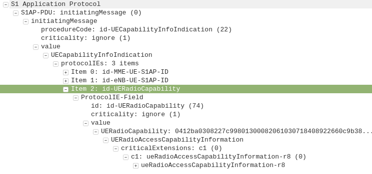
The NAS part of this request contains key information about our UE and it’s capabilities, most importantly it includes the IMSI or TMSI of the subscriber, but also includes important information such as SRVCC support, different bands and RAN technologies it supports, codecs, but most importantly, the identity of the subscriber.
If this is a new subscriber to the network, the IMSI is sent as the subscriber identity, however wherever possible sending the IMSI is avoided, so if the subscriber has connected to the network recently, the M-TMSI is used instead of the IMSI, and the MME has a record of which M-TMSI to IMSI mapping it’s allocated.
Diameter: Authentication Information Request
MME to HSS
The MME does not have a subscriber database or information on the Crypto side of things, instead this functionality is offloaded to the HSS.
I’ve gone on and on about LTE UE/Subscriber authentication, so I won’t go into the details as to how this mechanism works, but the MME will send a Authentication-Information Request via Diameter to the HSS with the Username set to the Subscriber’s IMSI.
Diameter: Authentication Information Response
HSS to MME
Assuming the subscriber exists in the HSS, a Authentication-Information Answer will be sent back from the HSS via Diameter to the MME, containing the authentication vectors to send to the UE / subscriber.
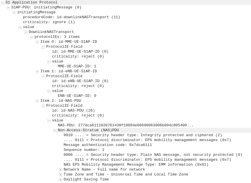
Now the MME has the Authentication vectors for that UE / Subscriber it sends back a DownlinkNASTransport, Authentication response, with the NAS section populated with the RAND and AUTN values generated by the HSS in the Authentication-Information Answer.
The Subscriber / UE’s USIM looks at the AUTN value and RAND to authenticate the network, and then calculates it’s response (RES) from the RAND value to provide a RES to send back to the network.
S1AP: UplinkNASTransport, Authentication response
eNB to MME
The subscriber authenticates the network based on the sent values, and if the USIM is happy that the network identity has been verified, it generates a RES (response) value which is sent in the UplinkNASTransport, Authentication response.
The MME compares the RES sent Subscriber / UE’s USIM against the one sent by the MME in the Authentication-Information Answer (the XRES – Expected RES).
If the two match then the subscriber is authenticated.
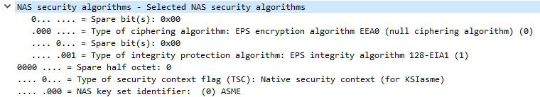
The DownlinkNASTransport, Security mode command is then sent by the MME to the UE to activate the ciphering and integrity protection required by the network, as set in the NAS Security Algorithms section;
The MME and the UE/Subscriber are able to derive the Ciphering Key (CK) and Integrity Key (IK) from the sent crypto variables earlier, and now both know them.
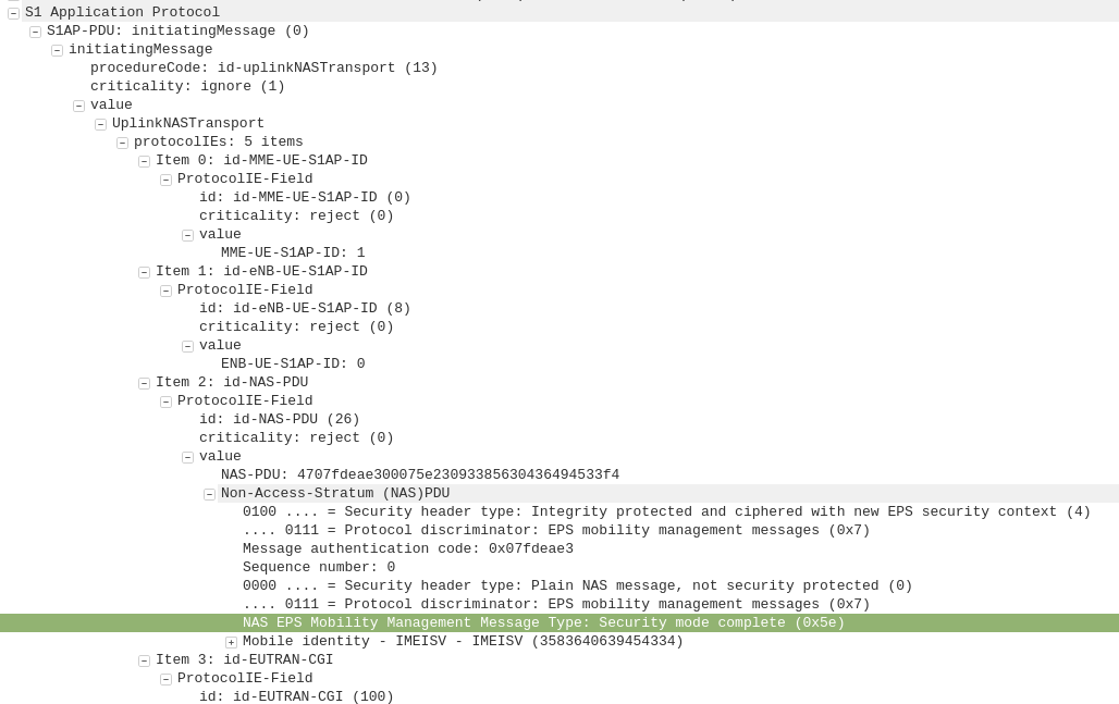
S1AP: UplinkNASTransport, Security mode complete
eNB to MME
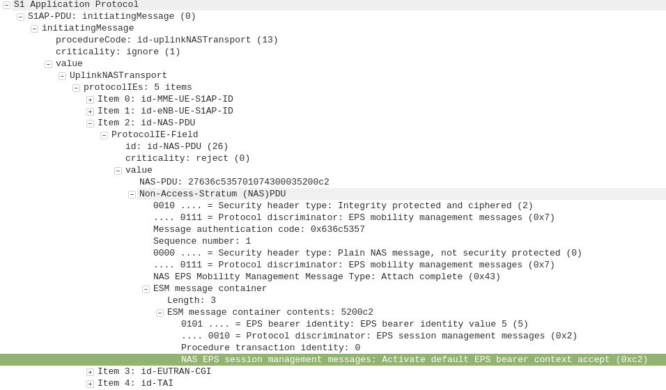
After the UE / Subscriber has derived the Ciphering Key (CK) and Integrity Key (IK) from the sent crypto variables earlier, it can put them into place as required by the NAS Security algorithms sent in the Security mode command request.
It indicates this is completed by sending the UplinkNASTransport, Security mode complete.
At this stage the authentication of the subscriber is done, and a default bearer must be established.
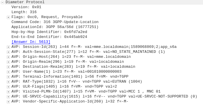
Diameter: Update Location Request
MME to HSS
Once the Security mode has been completed the MME signals to the HSS the Subscriber’s presence on the network and requests their Subscription-Data from the HSS.
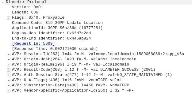
Diameter: Update Location Answer
HSS to MME
The ULA response contains the Subscription Data used to define the data service provided to the subscriber, including the AMBR (Aggregate Maximum Bit Rate), list of valid APNs and TAU Timer.
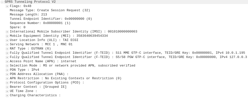
GTP-C: Create Session Request
MME to S-GW
The MME transfers the responsibility of setting up the data bearers to the S-GW in the form of the Create Session Request.
This includes the Tunnel Endpoint Identifier (TEID) to be assigned for this UE’s PDN.
The S-GW looks at the request and forwards it onto a P-GW for IP address assignment and access to the outside world.
GTP-C: Create Session Request
S-GW to P-GW
The S-GW sends a Create Session Request to the P-GW to setup a path to the outside world.
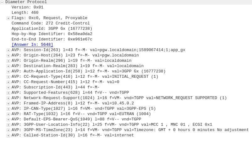
Diameter: Credit Control Request
P-GW to PCRF
To ensure the subscriber is in a state to establish a new PDN connection (not out of credit etc), a Credit Control Request is sent to the HSS.
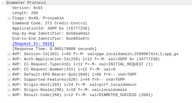
Diameter: Credit Control Answer
PCRF to P-GW
Assuming the Subscriber has adequate credit for this, a Credit Control Answer is sent and the P-GW and continue the PDN setup for the subscriber.
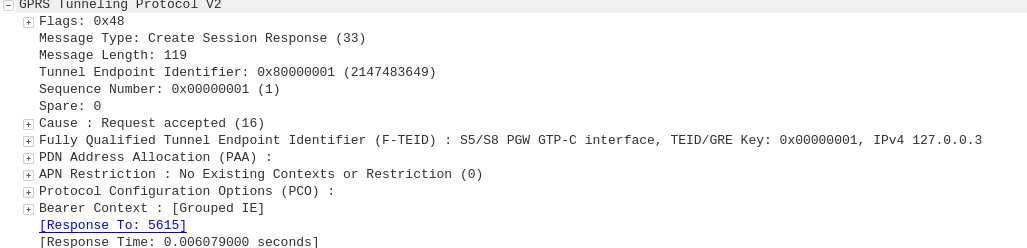
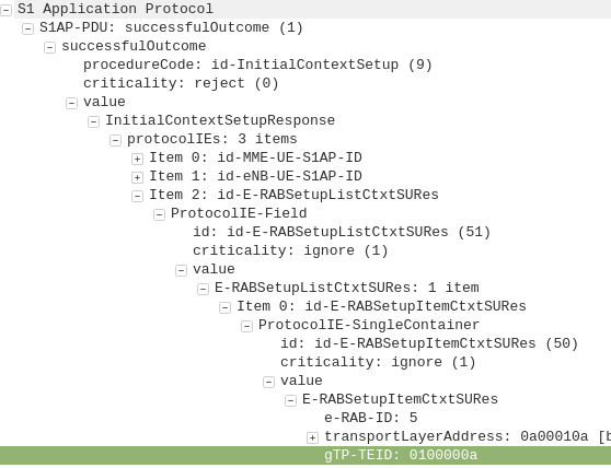
GTP-C: Create Session Response
P-GW to S-GW
The P-GW sends back a Create Session Response, containing the IP address allocated to this PDN (Framed-IP-Address).
GTP-C: Create Session Response
S-GW to MME
The S-GW slightly changes and then relays the Create Session Response back to the MME,
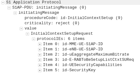
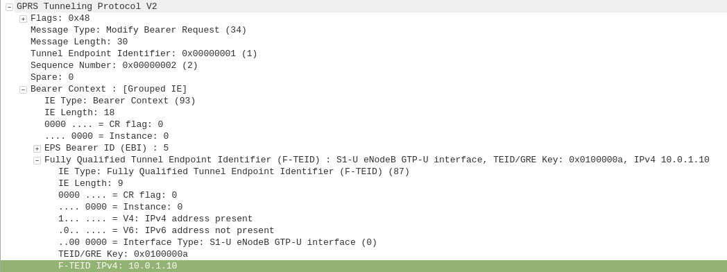
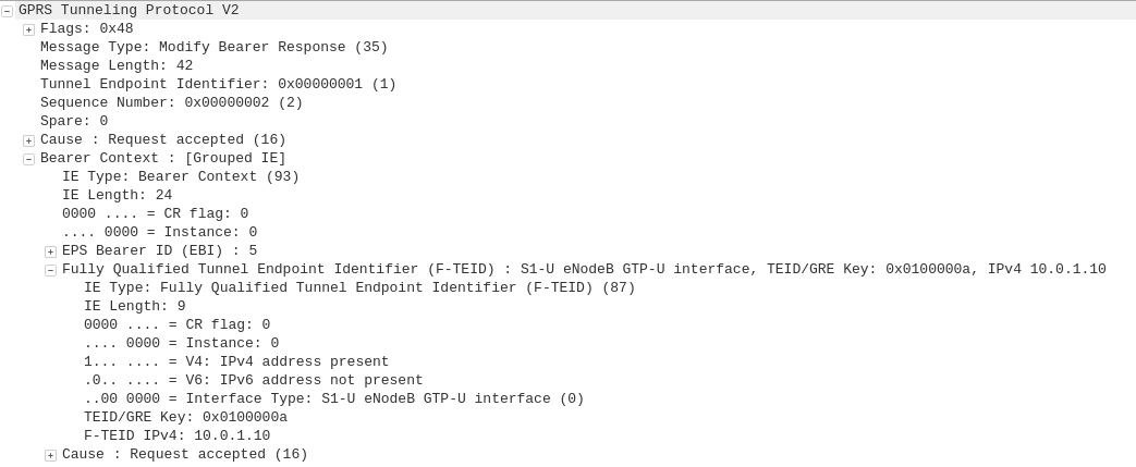
This message is sent to inform the eNB of the details of the PDN connection to be setup, ie AMBR, tracking area list, APN and Protocol Configuration Options,
This contains the Tunnel Endpoint Identifier (TEID) for this PDN to identify the GTP packets.
For my LTE lab I got myself a BaiCells Neutrino, it operates on Band 3 (FDD ~1800Mhz) with only 24dBm of output power max and PoE powered it works well in a lab environment without needing -48vDC supply, BBUs, DUs feeders and antennas.
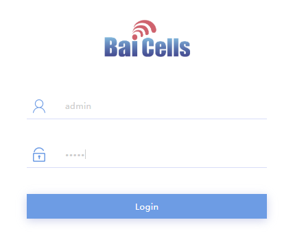
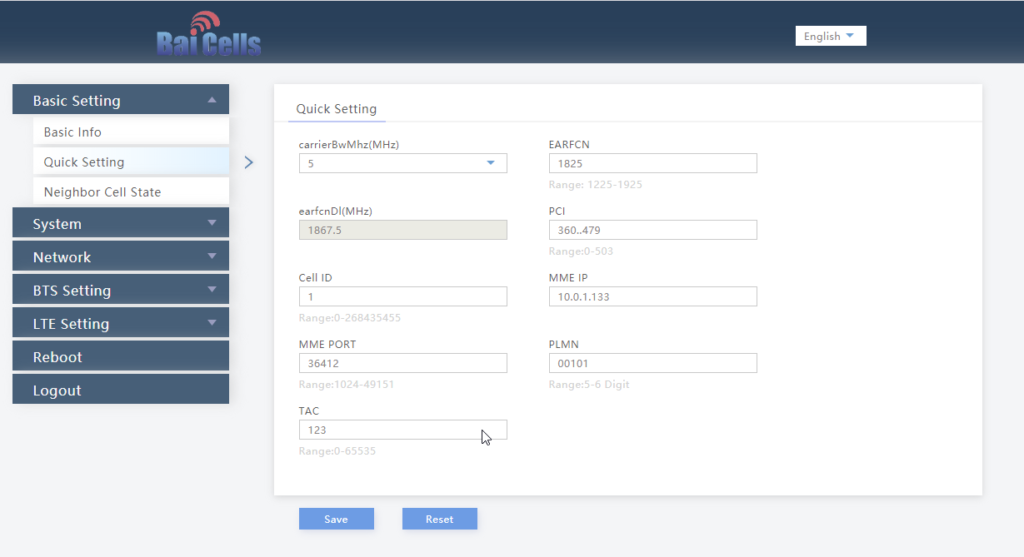
Setup can be done via TR-069 or via BaiCells management server, for smaller setups the web UI makes setup pretty easy,
Logging in with admin/admin to the web interface:
We’ll select Quick Settings, and load in our MME IP address, PLMN (MCC & MNC), Tracking Area Code, Cell ID and Absolute Radio Frequency No.
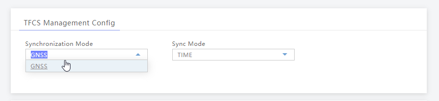
Once that’s done we’ll set our Sync settings to use GPS / GNSS (I’ve attached an external GPS Antenna purchased cheaply online).
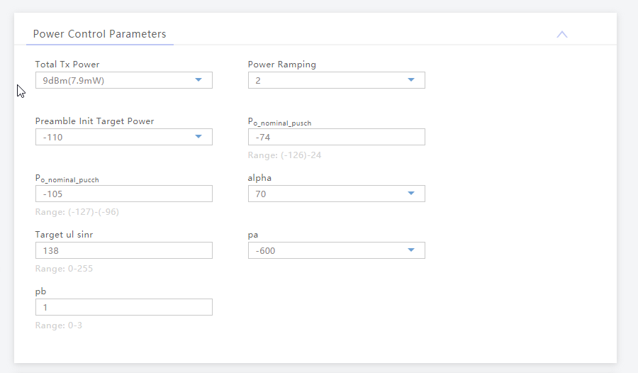
Finally we’ll set the power levels, my RF blocking setup is quite small so I don’t want excess power messing around with it, so I’ve dialed the power right back:
And that’s it, it’ll now connect to my MME on 10.0.1.133 port 36412 on SCTP.
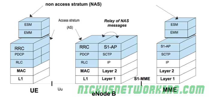
The LTE architecture compartmentalises the roles in the mobile network.
For example the eNB concentrates on radio connection management, while the MME focuses on security and mobility.
Non Access Stratum (NAS) messages are exchanged between the terminal and the MME.
Access Stratum (AS) messages are exchanged over the air between the UE and the eNB. It contains all the radio related information.
The eNB must map the NAS messages from an MME to a LCID and RNTI and transmit them over the air, and vice-versa. The eNB forwards this data without ever analyzing it.
To handle this load the requirements of each subscriber for the MME must be as minimal and simple as possible so as to scale easily.
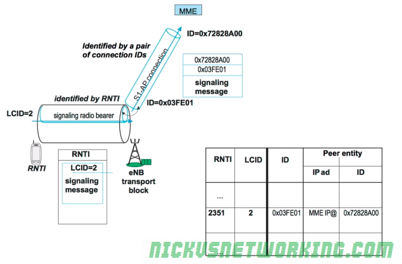
For each UE in the network a connection is setup between the UE and the MME.
This is done over the S1-AP’s Control Plane interface (sometimes calls S1-Control Plane or S1-CP) which carries control plane data to & from the UE via the eNB to the MME.
S1-CP is connection-oriented, meaning each UE has it’s own connection to the MME, so there are as many S1-CP connections to the MME as UE’s connected.
Each of these S1-CP connections is identified by a pair of unique connection IDs. The eNB keeps track of the connection IDs for each UE connected and hands this information off each time the UE moves to a different eNB.
The eNB keeps a lookup table between the RNTI of the UE and the LCID – the Logical Channel Identifier. This means that the eNB knows the sent and received ID of the S1-CP connection for each UE, and is able to translate that into the RNTI and LCID used to send the data over the air interface to the UE.
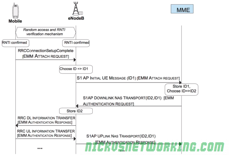
Once the RNTI is confirmed by both the eNB and the UE, a EMM Attach Request, which is put into an RRC Message called RRCConnectionSetupComplete.
The eNB must next choose a serving MME for this UE. It picks one based on it’s defined logic, and sends a S1-AP Intial UE Message (EMM Attach Request) to the MME along with the eNB’s connection identity assigned for this connection.
The MME stores the connection identity assigned by the eNB and chooses it’s own connection identity for it’s side, and sends back an S1AP Downlink NAS Transport response with both connection identities and the response for the attach request (This will be an EMM Authentication Request).
The eNB then stores the connection identity pair and the associated RNTI and LCID for the UE, and forwards the EMM Authentication Request to the RNTI of the UE via RRC.
The UE will pass the authentication challenge input parameters to the USIM which will generate a response. The UE will send the output of this response in a EMM Authentication Responseto the eNB, which will look at the RNTI and LCID received and consult the table to find the Connection Identifiers and IP of the serving MME for this UE.