Tag Archives: EUTRAN

NB-IoT NIDD Basics

NB-IoT introduces support for NIDD – Non-IP Data Delivery (NIDD) which is one of the cool features of NB-IoT that’s gaining more widespread adoption.

Let’s take a deep dive into NIDD.

The case against IP for IoT

In the over 40 years since IP was standardized, we’ve shoehorned many things onto IP, but IP was never designed or optimized for low power, low throughput applications.

For the battery life of an IoT device to be measured in years, it has to be very selective about what power hungry operations it does. Transmitting data over the air is one of the most power-intensive operations an IoT device can perform, so we need to do everything we can to limit how much data is sent, and how frequently.

Use Case – NB-IoT Tap

Let’s imagine we’re launching an IoT tap that transmits information about water used, as part of our revolutionary new “Water as a Service” model (WaaS) which removes the capex for residents building their own water treatment plant in their homes, and instead allows dynamic scaling of waterloads as they move to our new opex model.

If I turn on the tap and use 12L of water, when I turn off the tap, our IoT tap encodes the usage onto a single byte and sends the usage information to our rain-cloud service provider.

So we’re not constantly changing the batteries in our taps, we need to send this one byte of data as efficiently as possible, so as to maximize the battery life.

If we were to transport our data on TCP, well we’d need a 3 way handshake and several messages just to transmit the data we want to send.

Let’s see how our one byte of data would look if we transported it on TCP.

That sliver of blue in the diagram is our usage component, the rest is overhead used to get it there. Seems wasteful huh?

Sure, TCP isn’t great for this you say, you should use UDP! But even if we moved away from TCP to UDP, we’ve still got the IPv4 header and the UDP header wasting 28 bytes.

For efficiency’s sake (To keep our batteries lasting as long as possible) we want to send as few messages as possible, and where we do have to send messages, keep them very short, so IP is not a great fit here.

Enter NIDD – Non-IP Data Delivery.

Through NIDD we can just send the single hex byte, only be charged for the single hex byte, and only stay transmitting long enough to send this single byte of hex (Plus the NBIoT overheads / headers).

Compared to UDP transport, NIDD provides us a reduction of 28 bytes of overhead for each message, or a 96% reduction in message size, which translates to real power savings for our IoT device.

In summary – the more sending your device has to do, the more battery it consumes.
So in a scenario where you’re trying to maximize power efficiency to keep your batter powered device running as long as possible, needing to transmit 28 bytes of wasted data to transport 1 byte of usable data, is a real waste.

Delivering the Payload

NIDD traffic is transported as raw hex data end to end, this means for our 1 byte of water usage data, the device would just send the hex value to be transferred and it’d pop out the other end.

To support this we introduce a new network element called the SCEFService Capability Exposure Function.

From a developer’s perspective, the SCEF is the gateway to our IoT devices. Through the RESTful API on the SCEF (T8 API), we can send and receive raw hex data to any of our IoT devices.

When one of our Water-as-a-Service Taps sends usage data as a hex byte, it’s the software talking on the T8 API to the SCEF that receives this data.

Data of course needs to be addressed, so we know where it’s coming from / going to, and T8 handles this, as well as message reliability, etc, etc.

This is a telco blog, so we should probably cover the MME connection, the MME talks via Diameter to the SCEF. In our next post we’ll go into these signaling flows in more detail.

If you’re wondering what the status of Open Source SCEF implementations are, then you may have already guessed I’m working on one!

Hopefully by now you’ve got a bit of an idea of how NIDD works in NB-IoT, and in our next posts we’ll dig deeper into the flows and look at some PCAPs together.

Filtering for 3GPP DNS in Wireshark

If you work with IMS or Packet Core, there’s a good chance you need DNS to work, and it doesn’t always.

When I run traces, I’ve always found I get swamped with DNS traffic, UE traffic, OS monitoring, updates, etc, all combine into a big firehose – while my Wireshark filters for finding EPC and IMS traffic is pretty good, my achilles heel has always been filtering the DNS traffic to just get the queries and responses I want out of it.

Well, today I made that a bit better.

By adding this to your Wireshark filter:

dns contains 33:67:70:70:6e:65:74:77:6f:72:6b:03:6f:72:67:00

You’ll only see DNS Queries and Responses for domains at the 3gppnetwork.org domain.

This makes my traces much easier to read, and hopefully will do the same for you!

Bonus, here’s my current Wireshark filter for working EPC/IMS:

(diameter and diameter.cmd.code != 280) or  (sip and !(sip.Method == "OPTIONS") and !(sip.CSeq.method == "OPTIONS")) or (smpp and (smpp.command_id != 0x00000015 and smpp.command_id != 0x80000015)) or (mgcp and !(mgcp.req.verb == "AUEP") and !(mgcp.rsp.rspcode == 500)) or isup or sccp or rtpevent or s1ap or gtpv2 or pfcp or (dns contains 33:67:70:70:6e:65:74:77:6f:72:6b:03:6f:72:67:00)

Evolved Packet Core – Analysis Challenge

This post is one of a series of packet capture analysis challenges designed to test your ability to understand what is going on in a network from packet captures.
Download the Packet Capture and see how many of the questions you can answer from the attached packet capture.

The answers are at the bottom of this page, along with how we got to the answers.

This challenge focuses on the Evolved Packet Core, specifically the S1 and Diameter interfaces.

Why is the Subscriber failing to attach?

And what is the behavior we should be expecting to see?

What is the Cell ID of this eNodeB?

What is the Tracking Area?

That the subscriber is trying to attach in.

Does the device attaching to the network support VoLTE?

What type of IP is the subscriber requesting for this PDN session?

Is the device requesting an IPv4 address, IPv6 address or both?

What is the Diameter Application ID for S6a?

You should be able to ascertain this from information from the PCAP, without needing to refer to the standards.

What is the Crytpo RES returned by the HSS, and what is the RES returned by the SIM/UE?

Does this mean the subscriber was authenticated successfully?

Answers

Answer: Why is the Subscriber failing to attach?

The Diameter Update Location Request in frame 10 does not get answered by the HSS. After 5 seconds the MME gives up and rejects the connection.

Instead what should have happened is the HSS should have responded to the Update Location Request with an Update Location Answer, as we covered in the attach procedure.

Answer: What is the Cell ID of this eNodeB?

In Uplink messages from the eNodeB the EUTRAN-GCI field contains the Cell-ID of the eNodeB.

In this case the Cell-ID is 1.

Answer: What is the Tracking Area?

The tracking area is 123.

This information is available in the TAI field in the Uplink S1 messages.

Answer: Does the device attaching to the network support VoLTE?

No, the device does not support VoLTE.

There are a few ways we can get to this answer, and VoLTE support in the phone does not mean VoLTE will be enabled, but we can see the Voice Domain preference is set to CS Voice Only, meaning GSM/UMTS for voice calling.

This is common on cheaper handsets that do not support VoLTE.

Answer: What type of IP is the subscriber requesting for this PDN session? (IPv4/IPv6/Both)?

The subscriber is requesting an IPv4 address only.

We can see this in the ESM Message Container for the PDN Connectivity Request, the PDN type is “IPv4”.

Answer: What is the Diameter Application ID for S6a?

Answer: 16777251

This is shown for the Vendor-Specific-Application-Id AVP on an S6a message.

Answer: What is the Crytpo RES returned by the HSS, and what is the RES returned by the SIM/UE?

The RES (Response) and X-RES (Expected Response) Both are “dba298fe58effb09“, they do match, which means this subscriber was authenticated successfully.

You can learn more about what these values do in this post.

How UEs get Time in LTE

You may have noticed in the settings on your phone the time source can be set to “Network”, but what does this actually entail and how is this information transferred?

The answer is actually quite simple,

In the NAS PDU of the Downlink NAS Transport message from the MME to the UE, is the Time Zone & Time field, which contains (unsuprisingly) the Timezone and Time.

Time is provided in UTC form with the current Timezone to show the offset.

This means that in the configuration for each TAC on your MME, you have to make sure that the eNBs in that TAC have the Timezone set for the location of the cells in that TAC, which is especially important when working across timezones.

There is no parameter for the date/time when Daylight savings time may change. But as soon as a UE goes Idle and then comes out of Idle mode, it’ll be given the updated timezone information, and during handovers the network time is also provided.
This means if you were using your phone at the moment when DST begins / ends you’d only see the updated time once the UE toggles into/out of Idle mode, or when performing a tracking-area update.

PyHSS Update – SCTP Support

Pleased to announce that PyHSS now supports SCTP for transport.

If you’re not already aware SCTP is the surprisingly attractive cousin of TCP, that addresses head of line blocking and enables multi-homing,

The fantastic PySCTP library from P1sec made adding this feature a snap. If you’re looking to add SCTP to a Python project, it’s surprisingly easy,

A seperate server (hss_sctp.py) is run to handle SCTP connections, and if you’re looking for Multihoming, we got you dawg – Just edit the config file and set the bind_ip list to include each of your IPs to multi home listen on.

MTU in LTE & 5G Transmission Networks – Part 1

Every now and then when looking into a problem I have to really stop and think about how things work low down, that I haven’t thought about for a long time, and MTU is one of those things.

I faced with an LTE MTU issue recently I thought I’d go back and brush up on my MTU knowhow and do some experimenting.

Note: This is an IPv4 discussion, IPv6 does not support fragmentation.

The very, very basics

MTU is the Maximum Transmission Unit.

In practice this is the largest datagram the layer can handle, and more often than not, this is based on a physical layer constraint, in that different physical layers can only stuff so much into a frame.

“The Internet” from a consumer perspective typically has an MTU of 1500 bytes or perhaps a bit under depending on their carrier, such as 1472 bytes.
SANs in data centers typically use an MTU of around 9000 bytes,
Out of the box, most devices if you don’t specify, will use an MTU of 1500 bytes.

As a general rule, service providers typically try to offer an MTU as close to 1500 as possible.

Messages that are longer than the Maximum Transmission Unit need to be broken up in a process known as “Fragmenting”.
Fragmenting allows large frames to be split into smaller frames to make their way across hops with a lower MTU.

All about Fragmentation

So we can break up larger packets into smaller ones by Fragmenting them, so case closed on MTU right? Sadly not.

Fragmentation leads to reduced efficiency – Fragmenting frames takes up precious CPU cycles on the router performing it, and each time a frame is broken up, additional overhead is added by the device breaking it up, and by the receiver to reassemble it.

Fragmentation can happen multiple times across a path (Multi-Stage Fragmentation).
For example if a frame is sent with a length of 9000 bytes, and needs to traverse a hop with an MTU of 4000, it would need to be fragmented (broken up) into 3 frames (Frame 1 and Frame 2 would be ~4000 bytes long and frame 3 would be ~1000 bytes long).
If it then needs to traverse another hop with an MTU of 1500, then the 3 fragmented frame would each need to be further fragmented, with the first frame of ~4000 bytes being split up into 3 more fragmented frames.
Lost track of what just happened? Spare a thought for the routers having to to do the fragmentation and the recipient having to reassemble their packets.

Fragmented frames are reassembled by the end recipient, other devices along the transmission path don’t reassemble packets.

In the end it boils down to this trade off:
The larger the packet can be, the more user data we can stuff into each one as a percentage of the overall data. We want the percentage of user data for each packet to be as high as can be.
This means we want to use the largest MTU possible, without having to fragment packets.

Overhead eats into our MTU

A 1500 byte MTU that has to be encapsulated in IPsec, GTP or PPP, is no longer a 1500 byte MTU as far as the customer is concerned.

Any of these encapsulation techniques add overhead, which shrinks the MTU available to the end customer.

Keep in mind we’re going to be encapsulating our subscriber’s data in GTP before it’s transmitted across LTE/NR, and this means we’ll be adding:

  • 8 bytes for the GTP header
  • 8 bytes for the transport UDP header
  • 20 bytes for the transport IPv4 header
  • 14 bytes if our transport is using Ethernet

This means we’ve got 50 bytes of transmission / transport overhead. This will be important later on!

How do subscribers know what to use as MTU?

Typically when a subscriber buys a DSL service or HFC connection, they’ll either get a preconfigured router from their carrier, or they will be given a list of values to use that includes MTU.

LTE and 5G on the other hand tell us the value we should use.

Inside the Protocol Configuration Options in the NAS PDU, the UE requests the MTU and DNS server to be used, and is provided back from the network.

This MTU value is actually set on the MME, not the P-GW. As the MME doesn’t actually know the maximum MTU of the network, it’s up to the operator to configure this to be a value that represents the network.

Why this Matters for LTE & 5G Transmission

As we covered earlier, fragmentation is costly. If we’re fragmenting packets we are:

  • Wasting resources on our transmission network / core networks – as we fragment Subscriber packets it’s taking up compute resources and therefore limiting throughput
  • Wasting radio resources as additional overhead is introduced for fragmented packets, and additional RBs need to be scheduled to handle the fragmented packets

To test this I’ve setup a scenario in the lab, and we’ll look at the packet captures to see how the MTU is advertised, and see how big we can make our MTU on the subscriber side.

Enable GPS/GLONASS Sync on Huawei BTS3900

Our BTS is going to need an accurate clock source in order to run, so without access to crazy accurate Timing over Packet systems or TDM links to use as reference sources, I’ve opted to use the GPS/GLONASS receiver built into the LMPT card.

Add new GPS with ID 0 on LMPT in slot 7 of cabinet 1:

ADD GPS: GN=0, CN=1, SRN=7, CABLE_LEN=3, MODE=GPS/GLONASS;

Check GPS has sync (May take some time) using the Display GPS command;

DSP GPS: GN=0;

Assuming you’ve got an antenna connected and can see the sky, after ~10 minutes running the DSP GPS:; command again should show you an output like this:

+++    4-PAL0089624        2020-11-28 01:06:55
O&M    #806355684
%%DSP GPS: GN=0;%%
RETCODE = 0  Operation succeeded.

Display GPS State
-----------------
                 GPS Clock No.  =  0
                GPS Card State  =  Normal
                 GPS Card Type  =  M12M
                 GPS Work Mode  =  GPS
                   Hold Status  =  UNHOLDED
         GPS Satellites Traced  =  4
     GLONASS Satellites Traced  =  0
         BDS Satellites Traced  =  0
Antenna Longitude(1e-6 degree)  =  144599999
 Antenna Latitude(1e-6 degree)  =  -37000000
           Antenna Altitude(m)  =  613
         Antenna Angle(degree)  =  5
             Link Active State  =  Activated
              Feeder Delay(ns)  =  15
                   GPS Version  =  NULL
(Number of results = 1)


---    END

Showing the GPS has got sync and a location fix,

Next we set BTS to use GPS as time source,

SET TIMESRC: TIMESRC=GPS;

Finally we’ll verify the Time is in sync on the BTS using the list time command:

DSP TIME:;
+++    4-PAL0089624        2020-11-28 01:09:22
O&M    #806355690
%%DSP TIME:;%%
RETCODE = 0  Operation succeeded.

Time Information
----------------
Time  =  2020-11-28 01:09:22 GMT+00:00

---    END

Optionally you may wish to add a timezone, using the SET TZ:; command, but I’ve opted to keep it in UTC for simplicity.

Huawei BTS 3900 LMPT Basic Config

This post is one in a series documenting my adventures attempting to configure a used BTS 3900 to function as a eNB in my lab.

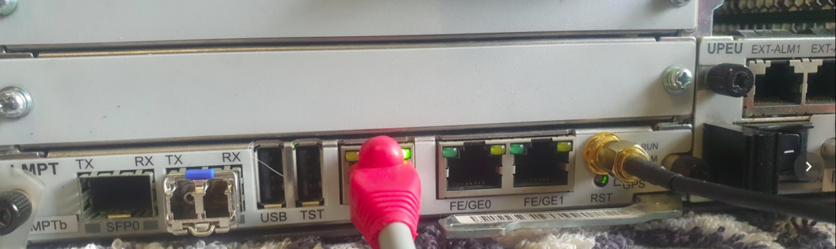
There are 5 network ports on the LMPT card:

  • 2x SFP cages – SFP 0 and SFP 1
  • 1x 10/100 Ethernet port – ETH – Used to access the Local Maintenance terminal
  • 2x Fe/Ge ports – Fe/Ge0 and Fe/Ge1

Configuring the Ethernet Ports

What took me a little while to realise is that SFP0 and Fe/Ge0 are paired, they’re really only one interface. This means you can only use one at a time – you can’t use SFP0 and Fe/Ge0 simultaneously- Same with SFP1 and Fe/Ge1.

Before we get started we’ll list the current interfaces:

DSP ETHPORT:;

Assuming the interfaces aren’t there, we’ll need to add the interfaces, in my case the LMPT card is in Chassis 1, Slot number 7.

ADD ETHPORT: SRN=1, SN=7, SBT=BASE_BOARD, PN=0, PA=AUTO, SPEED=AUTO, DUPLEX=AUTO, USERLABEL="SFP_Fe_Ge_0";
ADD ETHPORT: SRN=1, SN=7, SBT=BASE_BOARD, PN=1, PA=AUTO, SPEED=AUTO, DUPLEX=AUTO, USERLABEL="SFP_Fe_Ge_1";

And then we’ve got to add an IP to one of the interfaces, in the below example I’ve added 10.0.1.210/24 to port 0 (which can be either SFP0 or Fe/Ge0).

ADD DEVIP: SRN=1, SN=7, SBT=BASE_BOARD, PT=ETH, PN=0, IP="10.0.1.210", MASK="255.255.255.0", USERLABEL="SFP_Fe/Ge_0"; 

At this point I plugged into the Fe/Ge0 port into my switch, and from my laptop on the same 10.0.1.0/24 subnet, I was able to ping the eNodeB.

And now we can check the status of the port:

DSP ETHPORT: SRN=1, SN=7, SBT=BASE_BOARD, PN=0;
+++    4-PAL0089624        2020-11-28 00:19:13
O&M    #806355532
%%DSP ETHPORT: SRN=1, SN=7, SBT=BASE_BOARD;%%
RETCODE = 0  Operation succeeded.

DSP ETHPORT Result
------------------
                           Cabinet No.  =  0
                           Subrack No.  =  1
                              Slot No.  =  7
                         Subboard Type  =  Base Board
                              Port No.  =  0
                        Port Attribute  =  Copper
                           Port Status  =  Up
                 Physical Layer Status  =  Up
       Maximum Transmission Unit(byte)  =  1500
                             ARP Proxy  =  Enable
                          Flow Control  =  Open
                           MAC Address  =  DCD2-07FC-A9E8
                       Loopback Status  =  No Loop
               In Loopback Mode or Not  =  No
                 Ethernet OAM 3AH Flag  =  Disable
          Number of RX Packets(packet)  =  1682
              Number of RX Bytes(byte)  =  163929
Number of RX CRC Error Packets(packet)  =  2
                    RX Traffic(byte/s)  =  259
          Number of TX Packets(packet)  =  53
              Number of TX Bytes(byte)  =  13952
                    TX Traffic(byte/s)  =  0
  Local Configuration Negotiation Mode  =  Automatic Negotiation
         Local Actual Negotiation Mode  =  Automatic Negotiation
                           Local Speed  =  100M
                          Local Duplex  =  Full Duplex
          Peer Actual Negotiation Mode  =  Automatic Negotiation
                            Peer Speed  =  100M
                           Peer Duplex  =  Full Duplex
                         Number of IPs  =  1
                       IP Address List  =  10.0.1.210 255.255.255.0
(Number of results = 1)


---    END

On with the rest of the config,

Adding a default route:

ADD IPRT: RTIDX=0, SRN=1, SN=7, SBT=BASE_BOARD, DSTIP="0.0.0.0", DSTMASK="0.0.0.0", RTTYPE=NEXTHOP, NEXTHOP="10.0.1.1", MTUSWITCH=OFF, DESCRI="Default Route";

Setting a DNS Server:

ADD DNSSRV: DNSSRVID=0, IPVER=IPv4, DNSCIP4="10.0.1.210", DNSSIP4="1.1.1.1";

Ensure you can ping the DNS server & in my case the MME:

PING: SRN=1, SN=7, SRCIP="10.0.1.210", DSTIP="1.1.1.1", CONTPING=DISABLE, APPTIF=NO;
PING: SRN=1, SN=7, SRCIP="10.0.1.210", DSTIP="10.0.1.183", CONTPING=DISABLE, APPTIF=NO;

And with that, you’ve got the network side of the config done on the eNodeB.

At this stage you’re able to unplug from the ETH port you’ve got the WebLMT connection to, and just connect to it like any other network device.

There’s a few more steps before we bring cells on the air, we’ve got to set timing sources, configure a connection to an MME and S-GW, configure the Carrier settings and add the radios and sectors, but this will get you to the stage where you no longer need to plug directly into the eNB to configure it.

Huawei BTS3900 – MML Basics

How do humans talk to base stations? For Huawei at least the answer to this is through MML – Man-Machine-Language,

It’s command-response based, which is a throwback to my Nortel days (DMS100 anyone?),

So we’re not configuring everything through a series of parameters broken up into sections with config, it’s more statements to the BTS along the lines of “I want you to show me this”, or “Please add that” or “Remove this bit”,

The instruction starts of with an operation word, telling the BTS what we want to do, there’s a lot of them, but some common examples are; DSP (Display), LST (List), SET (Set), MOD (Modify) and ADD (Add).

After the operation word we’ve got the command word, to tell the BTS on what part we want to execute this command,

A nice simple example would be to list the software version that’s running on the BTS. For this we’d run

LST SOFTWARE:;

And press F9 to execute, which will return a list of software on the BTS and show it in the terminal.

Note at the end the :; – the : (colon) denotes the end of a command word, and after it comes the paratmeters for the command, and then the command ends with the ; (semi-colon). We’ll need to put this after every command.

Let’s look at one more example, and then we’ll roll up our sleves and get started.

Note: I’m trying out GIFs to share screen recordings instead of screenshots. Please let me know if you’re having issues with them.

So once you’ve logged into WebLMT, selecting MML is where we’ll do all our config, let’s log in and list the running applications.

So far we’ve only got some fairly basic data, listing and displaying values, so let’s try something a bit more complex, taking a backup of the config, in encrypted mode, with the backup label “blogexamplebackup”,

BKP CFGFILE: ENCRYPTMODE=UNENCRYPTED, BL="blogexamplebackup";

If you’ve made it this far there’s a good chance you’re thinking there’s no way you can remember all these commands and parameters – But I’ve got some good news, we don’t really need to remember anything, there’s a form for this!

And if we want to upload the backup file to an FTP server, we can do this as well, in the navigation tree we find Upload Backup Configuration, fill in the fields and click the Exec button to execute the command, or press F9.

These forms, combined with a healthy dose of the search tab, allow us to view and configure our BTS.

I’ve still got a lot to learn about getting end-to-end configuration in place, but this seems like a good place to start,

Indoor LTE/GSM/UMTS mobile antennas, primarily used for in building coverage.

DIY RAN Adventures – Antennas

Note: This is one part of a series of posts where I cover my adventures attempting to bring on air a commercial Macro cell site for my lab, with scrounged components.

So the Huawei BTS3900 unit I’ve ended up with, is only one part of the overall picture for building a working LTE RAN. Power systems, feeders, connectors, CPRI, antennas, baseband processing and transmission are all hurdles I’ve still got to overcome. So today, let’s talk about antennas!

For the output/TX side (downlink) of the RF Unit, I’ve ordered some 25w 50 ohm dummy loads (I’ll still need to work out how to turn down the RF power to less than 25w on the RF units). Even with the dummy load, a tiny bit of RF power is leaked, which should be enough to provide the downlink signal for my UEs – Time will tell if this works…

This option is fine for the power being pushed out of the RF unit, into the dummy load, where we have a lot of power available (too much power), but what about our very weak uplink signals from UEs?

For this I’d need some decent antennas to pickup the signals from the UEs, so I ended up with some Kathrein (Now owned by Ericsson) indoor multi-band omni antennas I found on an online auction site for $10 each. (I bought 4 so I can play with MIMO.)

Unfortunately, the RFUs I have are Band 28 (roughly 700Mhz-750Mhz uplink and 758Mhz to 798Mhz downlink), and reading the datasheet it seems this doesn’t cover the bands I need;

But beggars can’t be choosers, so I ran a calibration on the NanoVNA and swept the antenna from 700Mhz-750Mhz (Band 28 uplink frequencies) to see how it will perform when I get the rest of the solution together;

At the upper end of Band 28 Uplink (748Mhz) I’m getting a fairly respectable VSWR of 1.6 (Return Loss of -12.4dB), so I should be able to get away with these for what I’m doing,

I’v seen these white domes inside shopping centers and office buildings, so I was keen to crack open the case and see what magic inside, what I found was kind of underwhelming, just an aluminum plate with an aluminum reflector cone…

My ideas of putting the parts into the lathe and trying to lower it’s operating frequency by taking material off, were dashed when I realised taking material off would raise the operating frequency, not lower it…

Viewing the SIB – The LTE System Information Block with SDRs

I’ve been experimenting with Inter-RAT & Inter-Frequency handovers recetly, and had an issue where what I thought was configured on the eNB I wasn’t seeing reflected on the UEs.

I understood the Neighbouring Cell reelection parameters are broadcast in the System Information Blocks, but how could I view them?

The answer – srsUE!

I can’t get over how cool the stuff coming out of Software Radio Systems is, but being able to simulate a UE and eNB on SDR hardware is pretty awesome, and also allows you to view low layer traces the vast majority of commercial UEs will never expose to a user.

After running srsUE with the PCAP option I let it scan for networks and find mine. I didn’t actually need to authenticate with the network, just lock to the cell.

Deocoding it using the steps I laid out here for decoding LTE MAC traces in Wireshark, there it all was!

I’ve attached a copy of the pcap here for your reference.

Decoding MAC LTE Frames in Wireshark

Working with LTE MAC traces in Wireshark

I recently pulled MAC layer traces off an eNB and wanted to view them,

In Wireshark this shows up as raw data, and there’s no option to decode as LTE MAC from the Decode As menu.

Instead you’ve got to go to Preferences -> Protocols and select DLT_USER and then edit the encapsulation table.

For DLT_147 enter:

mac-lte-framed

Now you’ll have your MAC frames decoded:

On top of this there’s also now the option to run analysis on these traces,

By selecting Telephony -> LTE -> MAC Statistics you’re able to view stats for each RNTI connected to the eNB.

I’ve attached a copy of my trace for reference.

Multi Operator Core-Networks (MOCN) for RAN Sharing

MOCN is one of those great concepts I’d not really come across,

Multi-tenancy on the RAN side of the network, allowing an eNB to broadcast multiple PLMN IDs (MCC/MNC) in the System Information Block (SIB).

It allows site sharing not just on the tower itself, but site sharing on the RAN side, allowing customers of MNO A to see themselves connected to MNO A, and customers from MNO B see themselves as connected to MNO B, but they’re both connected to the same RAN hardware.

Setup in my lab was a breeze; your RAN hardware will probably be different.

In terms of signaling it’s a standard S1AP Setup Request except with multiple broadcast PLMN keys:

Now when I run a manual cell selection on my UE I can see the PLMN 460/11 as well as the Open5gs 00101 PLMN:

BaiCells Neutrino eNB Setup

For my LTE lab I got myself a BaiCells Neutrino, it operates on Band 3 (FDD ~1800Mhz) with only 24dBm of output power max and PoE powered it works well in a lab environment without needing -48vDC supply, BBUs, DUs feeders and antennas.

Setup can be done via TR-069 or via BaiCells management server, for smaller setups the web UI makes setup pretty easy,

Logging in with admin/admin to the web interface:

We’ll select Quick Settings, and load in our MME IP address, PLMN (MCC & MNC), Tracking Area Code, Cell ID and Absolute Radio Frequency No.

Once that’s done we’ll set our Sync settings to use GPS / GNSS (I’ve attached an external GPS Antenna purchased cheaply online).

Finally we’ll set the power levels, my RF blocking setup is quite small so I don’t want excess power messing around with it, so I’ve dialed the power right back:

And that’s it, it’ll now connect to my MME on 10.0.1.133 port 36412 on SCTP.

SRS LTE – Software Defined LTE Stack with BladeRF x40

The team at Software Radio Systems in Ireland have been working on an open source LTE stack for some time, to be used with software defined radio (SDR) hardware like the USRP, BladeRF and LimeSDR.

They’ve released SRSUE and SRSENB their open source EUTRAN UE and eNodeB, which allow your SDR hardware to function as a LTE UE and connect to a commercial eNB like a standard UE while getting all the juicy logs and debug info, or as a LTE eNB and have commercial UEs connect to a network you’re running, all on COTS hardware.

The eNB supports S1AP to connect to a 3GPP compliant EPC, like Open5Gs, but also comes bundled with a barebones EPC for testing.

The UE allows you to do performance testing and gather packet captures on the MAC & PHY layers, something you can’t do on a commericial UE. It also supports software-USIMs (IMSI / K / OP variables stored in a text file) or physical USIMs using a card reader.

I’ve got a draw full of SDR hardware, from the first RTL-SDR dongle I got years ago, to a few HackRFs, a LimeSDR up to the BladeRF x40.

Really cool software to have a play with, I’ve been using SRSUE to get a better understanding of the lower layers of the Uu interface.

Installation

After mucking around trying to satisfy all the dependencies from source I found everything I needed could be found in Debian packages from the repos of the maintainers.

To begin with we need to install the BladeRF drivers and SopySDR modules to abstract it to UHD:

sudo add-apt-repository -y ppa:myriadrf/drivers
sudo add-apt-repository -y ppa:bladerf/bladerf
apt-get install *bladerf*
apt-get install libgnuradio-uhd3.7.11 libuhd-dev soapysdr-module-uhd uhd-soapysdr

Next up installing Software Radio System’s repo:

sudo add-apt-repository -y ppa:srslte/releases
sudo apt-get update
sudo apt-get install srslte -y 

And that’s it!

PLMN Identity from Wireshark in Hex Form

PLMN Identifier Calculation (MCC & MNC to PLMN)

Note: This didn’t handle 3 digit MNCs, an updated version is available here and in the code sample below.

The PLMN Identifier is used to identify the radio networks in use, it’s made up of the MCC – Mobile Country Code and MNC – Mobile Network Code.

But sadly it’s not as simple as just concatenating MCC and MNC like in the IMSI, there’s a bit more to it.

In the example above the Tracking Area Identity includes the PLMN Identity, and Wireshark has been kind enough to split it out into MCC and MNC, but how does it get that from the value 12f410?

This one took me longer to work out than I’d like to admit, and saw me looking through the GSM spec, but here goes:

PLMN Contents: Mobile Country Code (MCC) followed by the Mobile Network Code (MNC).
Coding: according to TS GSM 04.08 [14].

If storage for fewer than the maximum possible number n is required, the excess bytes shall be set to ‘FF’. For instance, using 246 for the MCC and 81 for the MNC and if this is the first and only PLMN, the contents reads as follows: Bytes 1-3: ’42’ ‘F6′ ’18’ Bytes 4-6: ‘FF’ ‘FF’ ‘FF’ etc.

TS GSM 04.08 [14].

Making sense to you now? Me neither.

Here’s the Python code I wrote to encode MCC and MNCs to PLMN Identifiers and to decode PLMN into MCC and MNC, and then we’ll talk about what’s happening:

def Reverse(str):
    stringlength=len(str)
    slicedString=str[stringlength::-1]
    return (slicedString)    

def DecodePLMN(plmn):
    print("Decoding PLMN: " + str(plmn))
    
    if "f" in plmn:
        mcc = Reverse(plmn[0:2]) + Reverse(plmn[2:4]).replace('f', '')
        print("Decoded MCC: " + str(mcc))
        mnc = Reverse(plmn[4:6])
    else:
        mcc = Reverse(plmn[0:2]) + Reverse(plmn[2:4][1])
        print("Decoded MCC: " + str(mcc))
        mnc = Reverse(plmn[4:6]) + str(Reverse(plmn[2:4][0]))
    print("Decoded MNC: " + str(mnc))
    return mcc, mnc

def EncodePLMN(mcc, mnc):
        plmn = list('XXXXXX')
        if len(mnc) == 2:
            plmn[0] = Reverse(mcc)[1]
            plmn[1] = Reverse(mcc)[2]
            plmn[2] = "f"
            plmn[3] = Reverse(mcc)[0]
            plmn[4] = Reverse(mnc)[0]
            plmn[5] = Reverse(mnc)[1]
            plmn_list = plmn
            plmn = ''
        else:
            plmn[0] = Reverse(mcc)[1]
            plmn[1] = Reverse(mcc)[2]
            plmn[2] = Reverse(mnc)[0]
            plmn[3] = Reverse(mcc)[0]
            plmn[4] = Reverse(mnc)[1]
            plmn[5] = Reverse(mnc)[2]
            plmn_list = plmn
            plmn = ''
        for bits in plmn_list:
            plmn = plmn + bits
        print("Encoded PLMN: " + str(plmn))
        return plmn

EncodePLMN('505', '93')
EncodePLMN('310', '410')

DecodePLMN("05f539")
DecodePLMN("130014")

In the above example I take MCC 505 (Australia) and MCC 93 and generate the PLMN ID 05f539.

The first step in decoding is to take the first two bits (in our case 05 and reverse them – 50, then we take the third and fourth bits (f5) and reverse them too, and strip the letter f, now we have just 5. We join that with what we had earlier and there’s our MCC – 505.

Next we get our MNC, for this we take bytes 5 & 6 (39) and reverse them, and there’s our MNC – 93.

Together we’ve got MCC 505 and MNC 93.

The one answer I’m still looking for; why not just encode 50593? What is gained by encoding it as 05f539?

Authentication Vectors and Key Distribution in LTE

Querying Auth Credentials from USIM/SIM cards

LTE has great concepts like NAS that abstract the actual transport layers, so the NAS packet is generated by the UE and then read by the MME.

One thing that’s a real headache about private LTE is the authentication side of things. You’ll probably bash your head against a SIM programmer for some time.

As your probably know when connecting to a network, the UE shares it’s IMSI / TIMSI with the network, and the MME requests authentication information from the HSS using the Authentication Information Request over Diameter.

The HSS then returns a random value (RAND), expected result (XRES), authentication token (AUTN) and a KASME  for generating further keys,

The RAND and AUTN values are sent to the UE, the USIM in the UE calculates the RES (result) and sends it back to the MME. If the RES value received by the MME is equal to the expected RES (XRES) then the subscriber is mutually authenticated.

The osmocom guys have created a cool little utility called osmo-sim-auth, which allows you to simulate the UE’s baseband module’s calls to the USIM to authenticate.

Using this tool I was able to plug a USIM into my USIM reader, using the Diameter client built into PyHSS I was able to ask for Authentication vectors for a UE using the Authentication Information Request to the HSS and was sent back the Authentication Information Answer containing the RAND and AUTN values, as well as the XRES value.

Wireshark Diameter Authentication Information Response message body looking at the E-UTRAN vectors
Diameter – Authentication Information Response showing E-UTRAN Vectors

Then I used the osmo-sim-auth app to query the RES and RAND values against the USIM.

Osmocom's USIM Test tool - osmo-sim-auth

The RES I got back matched the XRES, meaning the HSS and the USIM are in sync (SQNs match) and they mutually authenticated.

Handy little tool!

Information stored on USIM / SIM Card for LTE / EUTRAN / EPC - K key, OP/OPc key and SQN Sequence Number

HSS & USIM Authentication in LTE/NR (4G & 5G)

I talked a bit in my last post about using osmo-sim-auth to authenticate against a USIM / SIM card when it’s not in a phone,

I thought I’d expand a little on how the Crypto side of things works in LTE & NR (also known as 4G & 5G).

Authentication primarily happens in two places, one at each end of the network, the Home Subscriber Server and in the USIM card. Let’s take a look at each of them.

On the USIM

On the USIM we’ve got two values that are entered in when the USIM is provisioned, the K key – Our secret key, and an OPc key (operator key).

These two keys are the basis of all the cryptography that goes on, so should never be divulged.

The only other place to have these two keys in the HSS, which associates each K key and OPc key combination with an IMSI.

The USIM also stores the SQN a sequence number, this is used to prevent replay attacks and is incremented after each authentication challenge, starting at 1 for the first authentication challenge and counting up from there.

On the HSS

On the HSS we have the K key (Secret key), OPc key (Operator key) and SQN (Sequence Number) for each IMSI on our network.

Each time a IMSI authenticates itself we increment the SQN, so the value of the SQN on the HSS and on the USIM should (almost) always match.

Authentication Options

Let’s imagine we’re designing the authentication between the USIM and the Network; let’s look at some options for how we can authenticate everyone and why we use the process we use.

Failed Option 1 – Passwords in the Clear

The HSS could ask the USIM to send it’s K and OPc values, compare them to what the HSS has in place and then either accept or reject the USIM depending on if they match.

The obvious problem with this that to send this information we broadcast our supposedly secret K and OPc keys over the air, so anyone listening would get our secret values, and they’re not so secret anymore.

This is why we don’t use this method.

Failed Option 2 – Basic Crypto

So we’ve seen that sending our keys publicly, is out of the question.

The HSS could ask the USIM to mix it’s K key and OPc key in such a way that only someone with both keys could unmix them.

This is done with some cryptographic black magic, all you need to know is it’s a one way function you enter in values and you get the same result every time with the same input, but you can’t work out the input from the result.

The HSS could then get the USIM to send back the result of mixing up both keys, mix the two keys it knows and compare them.

The HSS mixes the two keys itself, and get’s it’s own result called XRES (Expected Result). If the RES (result) of mixing up the keys by the USIM is matches the result when the HSS mixes the keys in the same way (XRES (Expected Result)), the user is authenticated.

The result of mixing the keys by the USIM is called RES (Result), while the result of the HSS mixing the keys is called XRES (Expected Result).

This is a better solution but has some limitations, because our special mixing of keys gets the same RES each time we put in our OPc and K keys each time a subscriber authenticates to the network the RES (result) of mixing the keys is going to be the same.

This is vulnerable to replay attacks. An attacker don’t need to know the two secret keys (K & OPc) that went into creating the RES (resulting output) , the attacker would just need to know the result of RES, which is sent over the air for anyone to hear.
If the attacker sends the same RES they could still authenticate.

This is why we don’t use this method.

Failed Option 3 – Mix keys & add Random

To prevent these replay attacks we add an element of randomness, so the HSS generates a random string of garbage called RAND, and sends it to the USIM.

The USIM then mixes RAND (the random string) the K key and OPc key and sends back the RES (Result).

Because we introduced a RAND value, every time the RAND is different the RES is different. This prevents against the replay attacks we were vulnerable to in our last example.

If the result the USIM calculated with the K key, OPc key and random data is the same as the USIM calculated with the same K key, OPc key and same random data, the user is authenticated.

While an attacker could reply with the same RES, the random data (RAND) will change each time the user authenticates, meaning that response will be invalid.

While an attacker could reply with the same RES, the random data (RAND) will change each time the user authenticates, meaning that response will be invalid.

The problem here is now the network has authenticated the USIM, the USIM hasn’t actually verified it’s talking to the real network.

This is why we don’t use this method.

GSM authentication worked like this, but in a GSM network you could setup your HLR (The GSM version of a HSS) to allow in every subscriber regardless of what the value of RES they sent back was, meaning it didn’t look at the keys at all, this meant attackers could setup fake base stations to capture users.

Option 4 – Mutual Authentication (Real World*)

So from the previous options we’ve learned:

  • Our network needs to authenticate our subscribers, in a way that can’t be spoofed / replayed so we know who to bill & where to route traffic.
  • Our subscribers need to authenticate the network so they know they can trust it to carry their traffic.

So our USIM needs to authenticate the network, in the same way the network authenticates the USIM.

To do this we introduce a new key for network authentication, called AUTN.

The AUTN key is generated by the HSS by mixing the secret keys and RAND values together, but in a different way to how we mix the keys to get RES. (Otherwise we’d get the same key).

This AUTN key is sent to the USIM along with the RAND value. The USIM runs the same mixing on it’s private keys and RAND the HSS did to generate the AUTN , except this is the USIM generated – An Expected AUTN key (XAUTN). The USIM compares XAUTN and AUTN to make sure they match. If they do, the USIM then knows the network knows their secret keys.

The USIM then does the same mixing it did in the previous option to generate the RES key and send it back.

The network has now authenticated the subscriber (HSS has authenticated the USIM via RES key) and the subscriber has authenticated the USIM (USIM authenticates HSS via AUTN key).

*This is a slightly simplified version of how EUTRAN / LTE authentication works between the HSS and the USIM – In reality there are a few extra values, such as SQN to take into consideration and the USIM talks to to the MME not the HSS directly.

I’ll do a follow up post covering the more nitty-gritty elements, AMF and SQN fields, OP vs OPc keys, SQN Resync, how this information is transfered in the Authentication Information Answer and how KASME keys are used / distributed.

LTE / EUTRAN – Idle Detach

In order to keep radio resources free, if a UE doesn’t send or receive data for a predefined threshold, it’ll detach from the network and call back to Idle mode.

If the UE has data to send to the network, the UE will re-attach to the network, whereas if the network has data to send to the UE, it’ll Page the UE in the tracking area it’s currently in, the UE is always listening for it’s identifier (s-TMSI) on the paging channel, and if it hears it’s identifier called, the UE will re-attach.

I’ve also attached a PCAP file of the packet flow between the eNB and the MME.

UEContextReleaseRequest [RadioNetwork-cause=user-inactivity]

The first packet is sent by the eNB to the serving MME to indicate the user wishes to detach from the network.

PCAP of UEContextReleaseRequest from eNB to MME

UEContextReleaseCommand [NAS-cause=normal-release]

The next packet is sent from the MME back to the eNB confirming UE is releasing from the network.

UEContextReleaseCommand

UEContextReleaseComplete

Finally after the UE has released it’s radio resources the eNB sends a UEContextReleaseComplete so the MME knows the UE is now in Idle state and will need to be paged.

UEContextReleaseComplete response

Subscribed-Periodic-RAU-TAU-Timer

https://github.com/open5gs/nextepc/issues/238

Recently we saw Open5Gs’s Update Location Answer response putting the Subscribed-Periodic-RAU-TAU-Timer AVP in the top level and not in the AVP Code 1400 (APN Configuration) Diameter payload from the HSS to the MME.

But what exactly does the Subscribed-Periodic-RAU-TAU-Timer AVP in the Update Location Answer response do?

Folks familiar with EUTRAN might recognise TAU as Tracking Area Update, while RAU is Routing Area Update in GERAN/UTRAN (UMTS).

Periodic tracking area updating is used to periodically notify the availability of the UE to the network. The procedure is controlled in the UE by the periodic tracking area update timer (timer T3412). The value of timer T3412 is sent by the network to the UE in the ATTACH ACCEPT message and can be sent in the TRACKING AREA UPDATE ACCEPT message. The UE shall apply this value in all tracking areas of the list of tracking areas assigned to the UE, until a new value is received.

Section 5.3.5 of 24301-9b0 (3GPP TS 24.301 V9.11.0)

So the Periodic Tracking Area Update timer simply defines how often the UE should send a Tracking Area Update when stationary (not moving between cells / tracking area lists).