We’ve already touched on how subscribers are authenticated to the network, how the network is authenticated to subscribers and how the key hierarchy works for encryption of user data and control plane data.
If the IMSI was broadcast in the clear over the air, anyone listening would have the unique identifier of the subscriber nearby and be able to track their movements.
We want to limit the use of the IMSI over the air to a minimum.
During the first exchange the terminal is forced to send it’s IMSI, it’s the only way we can go about authenticating to the network, but once the terminal is authenticated and encryption of the radio link has been established, the network allocates a temporary identifier to the terminal, called the Temporary Mobile Subscriber Identity (TMSI) by the serving MME.
The TMSI is given to the terminal once encryption is setup, so only the network and the terminal know the mapping between IMSI and TMSI.
The TMSI is used for all future communication between the Network and the Terminal, hiding the IMSI.
The TMSI can be updated / changed at regular intervals to ensure the IMSI-TMSI mapping cannot be ascertained by a process of elimination.
The TMSI is short – only 4 bytes long – and this only has significance for the serving MME.
For the network to ascertain what MME is serving what TMSI the terminal is also assigned a Globally Unique Temporary (UE) Identity (GUTI), to identify the MME that knows the TMSI to IMSI mapping.
The GUTI is made up of the MNC/MCC combination, then an MME group ID to identify the MME group the serving MME is in, a MME code to identify the MME that allocated the TMSI and finally the TMSI itself.
The decision to use the TMSI or GUTI in a dialog is dependant on the needs of the dialog and what information both sides have. For example in an MME change the GUTI is needed so the original IMSI can be determined by the new MME, while in a normal handover the TMSI is enough.
We’ve talked a bit in the past few posts about keys, K and all it’s derivatives, such as Kenc, Kint, etc.
Each of these is derived from our single secret key K, known only to the HSS and the USIM.
To minimise the load on the HSS, the HSS transfers some of the key management roles to the MME, without ever actually revealing what the secret key K actually is to the MME.
This means the HSS is only consulted by the MME when a UE/Terminal attaches to the network, and not each time it attaches to different cell etc.
When the UE/Terminal first attaches to the network, as outlined in my previous post, the HSS also generates an additional key it sends to the MME, called K-ASME.
K-ASME is the K key derived value generated by the HSS and sent to the MME. It sands for “Access Security Management Entity” key.
When the MME has the K-ASME it’s then able to generate the other keys for use within the network, for example the Kenb key, used by the eNodeB to generate the keys required for communications.
The USIM generates the K-ASME itself, and as it’s got the same input parameters, the K-ASME generated by the USIM is the same as that generated by the HSS.
The USIM can then give the terminal the K-ASME key, so it can generate the same Kenb key required to generate keys for complete communications.
We’ve already touched on how subscribers are authenticated to the network, how the network is authenticated to subscribers.
Those functions are done “in the clear” meaning anyone listening can get a copy of the data transmitted, and responses could be spoofed or faked.
To prevent this, we want to ensure the data is ciphered (encrypted) and the integrity of the data is ensured (no one has messed with our packets in transmission or is sending fake packets).
Ciphering of Messages
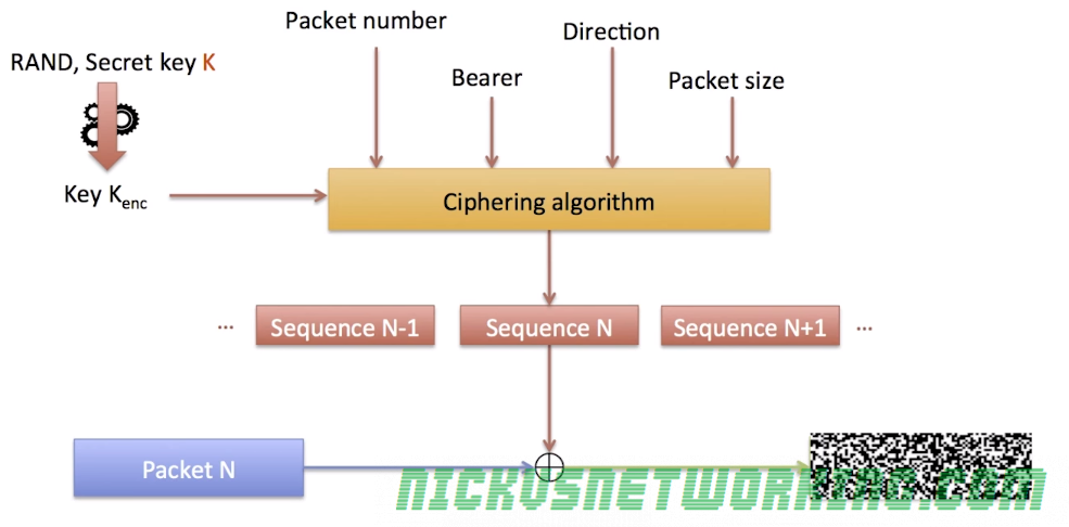
Before being transmitted over the Air interface (Uu) each packet is encrypted to prevent eavesdropping.
This is done by taking the plain text data and a ciphering sequence for that data of the same length as the packet and XORing two.
The terminal and the eNodeB both generate the same ciphering sequence for that data.
This means to get the ciphered version of the packet you simply XOR the Ciphering Sequence and the Plain text data.
To get the plain text from the ciphered packet you simply XOR the ciphered packet and ciphering sequence.
The Ciphering Sequence is made up of parts known only to the Terminal and the Network (eNB), meaning anyone listening can’t deduce the same ciphering sequence.
The Ciphering Sequence is derived from the following input parameters:
Key Kenc
Packet Number
Bearer Number
Direction (UL/DL)
Packet Size
Is is then ciphered using a ciphering algorithm, 3GPP define two options – AES or SNOW 3G. There is an option to not generate a ciphering sequence at all, but it’s not designed for use in production environments for obvious reasons.
Ciphering Sequences are never reused, the packet number increments with each packet sent, and therefore a new Cipher Sequence is generated for each.
Someone listening to the air interface (Uu) may be able to deduce packet size, direction and even bearer, but without the packet number and secret key Kenc, the data won’t be readable.
Data Integrity
By using the same ciphering sequence & XOR process outlined above, we also ensure that data has not been manipulated or changed in transmission, or that it’s not a fake message spoofing the terminal or the eNB.
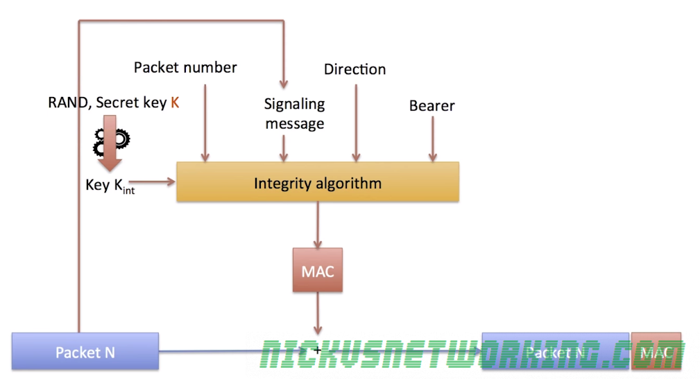
Each frame contains the packet and also a “Message Authentication Code” or “MAC” (Not to be confused with media access control), a 32 bit long cryptographic hash of the contents of the packet.
The sender generates the MAC for each packet and appends it in the frame,
The receiver looks at the contents of the packet and generates it’s own MAC using the same input parameters, if the two MACs (Generated and received) do not match, the packet is discarded.
This allows the receiver to detect corrupted packets, but does not prevent a malicious person from sending their own fake packets,
To prevent this the MAC hash function requires other input parameter as well as the packet itself, such as the secret key Kint, packet number, direction and bearer.
By adding this we ensure that the packet was sourced from a sender with access to all this data – either the terminal or the eNB.
The Radio Link Control (RLC) layer sits above the MAC layer and can manage:
Re-sequencing of blocks held up by HARQ
Concatenates / segments messages to fit into the size defined by the MAC layer
Re-transmits lost blocks (independent of ARQ)
These functions are set out and managed based on which of the 3 RLC Modes used based on QoS requirements of the traffic type.
RLC Modes
RLC has 3 services or modes that can be used depending on the type of data transmitted:
Transparent Mode (TM)
Does not offer any RLC features / services
Can only be used for short messages (As no segmentation to fit MAC requirements)
Mainly used for signaling messages
Unacknowledged Mode (UM)
Re-Sequences data if received out of order
Segments data according to MAC needs / limitations
Low latency but no re-transmission on the RLC layer
Suitable for VoLTE / real time communications
Does not re-transmit lost packets
Acknowledged Mode (AM)
Like UM but adds re transmission of lost packets
Higher latency but more reliable
Suitable for web browsing, file transfer, etc.
Upon valid receipt of a message the receiver sends an ACK on the data channel.
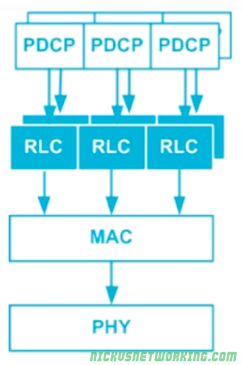
Several different RLC modes/services can be used at the same time by a single UE, as we saw in the last post:
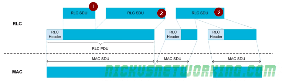
The MAC layer takes packets from each of the different RLC streams and packs them into MAC SDUs.
Here we can see 3 different RLC SDUs being packet into MAC SDUs.
RLC SDU 1 is packed into the a RLC PDU along with RLC SDU2. These two are concatenated together. RLC also adds a header to delineate the start of RLC SDU 1 and the start of RLC SDU 2.
The header allows the receiver to determine where each RLC SDU starts and ends and the sequence number of each RLC SDU.
Part of RLC SDU 3 is also packed into the first RLC PDU, and the second part is packed into the next RLC PDU. RLC is said to have segmented or fragmentedthis message as it splits it across multiple RLC PDUs for transmission. Again the RLC PDU adds headers to define that the data it contains is split across multiple RLC PDUs.
The MAC layer (Media Access Control) handles error correction, and performs multiplexing of services to the same UE at the same time (multiplexing).
Automatic Repeat Request (ARQ)
When data is sent a CRC (Cyclic Redunancy Check) is added, containing a checksum equivalent of the data contained in the message.
The receiver runs the same CRC calculation on the data, and if the CRC value is not equal to the CRC value it received it knows the data is not correct/complete.
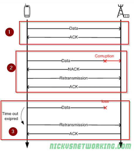
There are 3 scenarios shown below:
Scenario 1 – Data is sent and the CRC calculated by the sender matches the CRC calculated by the reciver. An ACK is sent to confirm the data was received correctly.
Scenario 2 – Data is sent and the CRC calculated by the sender does not match the CRC calculated by the receiver. The receiver sends a NACK (Negative Ack), The sender sends the data again, the CRC this time matches, so an ACK is sent to confirm the data was received correctly.
Scenario 3 – Data is sent by not ACK or NACK was received. This could mean the data was not received, or the ACK/NACK was not received. The sender then sends the message again. This process is repeated a set number of times after which if no response is received the sender gives up.
Acknowledgement
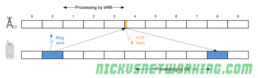
This technique is called Send and Wait ARQ, because the sender must send the data and wait for an ACK/NACK, and will automatically request re-transmission.
Because CRC may take some time to calculate the ACK/NACK is given time to process by the receiver and the ACK/NACK is sent 4ms after it was received.
If a NACK is received the data is re-transmitted 4ms after receipt of the NACK.
This means all up it takes up to 8ms (8 subframes) to send the data, wait for the response and send again if needed. During this time no other data would be sent.
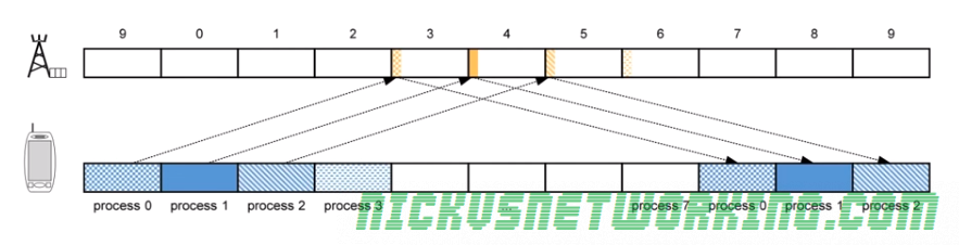
As you can imagine this isn’t a particularly efficient use of time or resources, so the EUTRAN specs define 8 Send and Wait processes in parallel.
While the first process is blocked waiting for an ACK/NACK, another process can transmit. This is called Parallel Send and Wait.
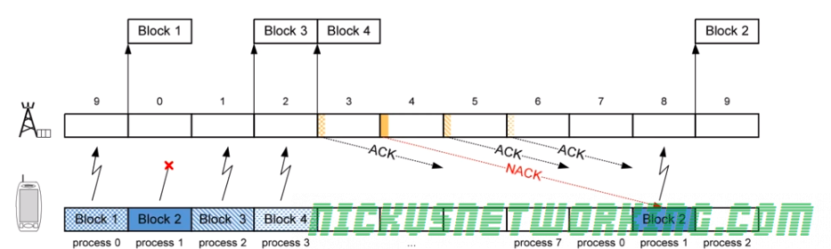
The problem with this is it can lead to data being received out of sequence, as if data is sent and a re-transmission is needed (NACK received by sender) that data will be received after the data sent 8 frames after it.
Here we can see Block 2 was lost, a NACK was sent and a re-transmission occurs 8 subframes later, long after Block 3 and Block 4 were received.
The MAC layer does not deal with re-sequencing, this is managed by the RLC layer above the MAC layer.
Hybrid ARQ
LTE relies on Hybrid ARQ. To increase redundancy and increase the possibility of decoding a corrupted message correctly.
We talked about coding – sending multiple copies of the same data and comparing them to find the common features that would indicate correct data, Hybrid ARQ functions in much the same way.
To increase error correction performance the receiver keeps the invalid/corrupt messages it sends a NACK for, so it can compare it to the re-transmitted version and hopefully correctly decode the message even if the re-transmission is corrupted.
It is called Hybird because the MAC layer has to communicate to the physical layer to let is know this is a re-transmission and not a new transmission.
Multiplexing on the MAC Layer
You may use your smartphone (UE) for a voice call while looking up something online and getting push notifications, while these are 3 distinct streams of data, there is only one stream of data to and from the eNB <-> UE.
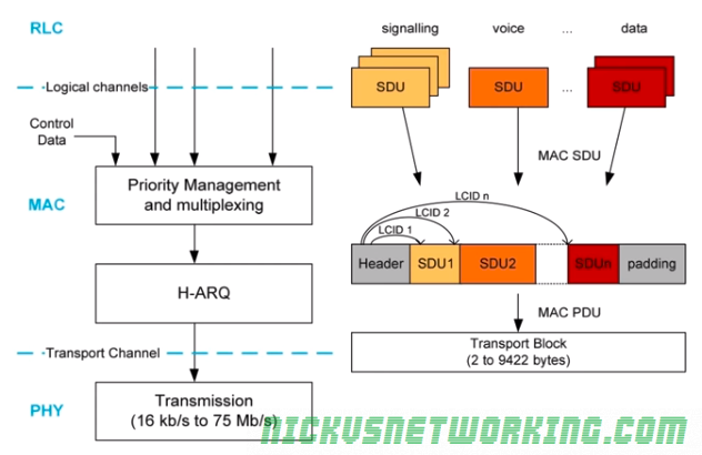
These different types of data all need to be combined into one “pipe” between the eNB and UE, this is known as multiplexing.
The RLC layer has multiple types of data arranged in logical channels, but this data has to be put into a MAC PDU and sent over the air.
In the standard networking model, data in an upper layer is called SDU “Service Data Units”, and data in a lower layer is called a PDU “Protocol Data Units”.
To form the transport blocks the MAC layer must take each of the SDUs from the RLC layer, and put it into the transport block, as show in the image above.
The MAC header contains the delineation of what data is for which SDU on the RLC layer.