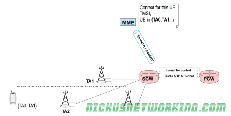
Let’s look at how the Tracking Area Updates work from the point of view of the network.
Let’s take an example of a UE which has been sent the Tracking Area List TA0 and TA1, which is currently in ECM_IDLE state served by eNBs in Tracking Area 1.
The UE is moving towards another eNB in Tracking Area 2. As the UE listens on the Broadcast Channel the power of the new eNB overtakes that of the previous eNB, but the UE notes the Tracking Area of the new eNB, which is not on the UE’s Tracking Area List.
So the UE must make a Tracking Area Update to inform the network.
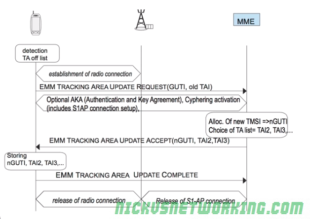
The first thing to do is to establish a radio connection.
Once the radio connection is setup a S1-AP connection is setup, upon which an NAS message – EMM Tracking Area Update Request is sent which contains the GUIT and old Tracking Area ID, which is sent to the MME.
The MME then sends back a new Tracking Area List for the UE and new TMSI to update the GUTI of the subscriber.
The UE updates it’s GUTI, updates it’s Tracking Area List, sends an EMM TRACKING AREA UPDATE COMPLETE and the UE returns to ECM_IDLE state.
As we’ve seen earlier, the eNB needs a connection to an MME and a S-GW.
However different eNBs may connect to different S-GWs or different MMEs, and our UE may connect to any eNB, so we need a way to handover between S-GWs and MMEs.
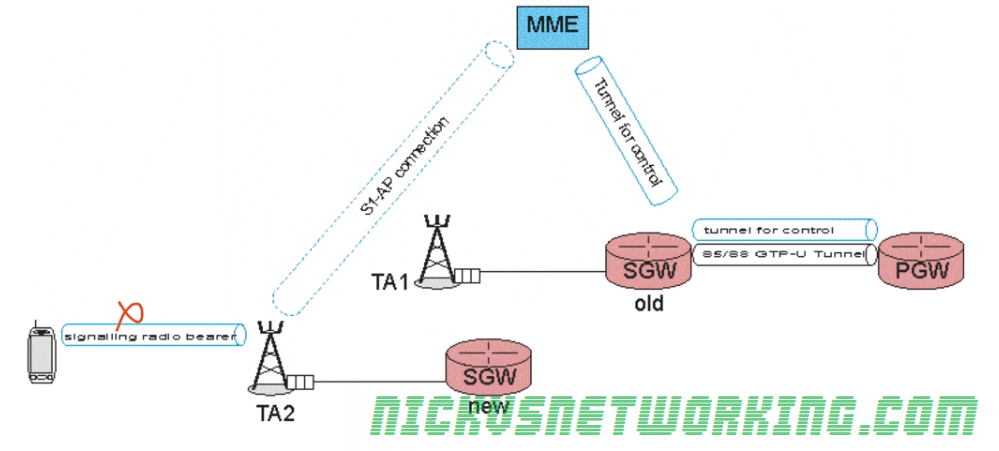
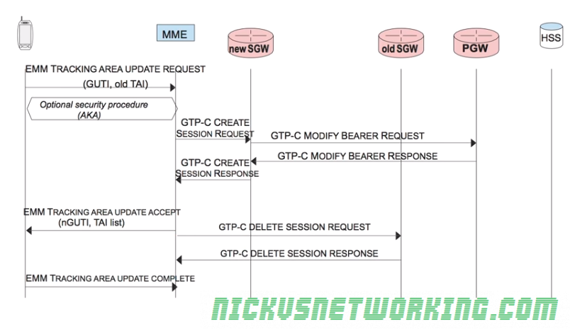
Handover to new S-GW
Let’s take a look at a scenario where a UE is moving from one eNB to another, and each of the two eNBs is in a different S-GW.
At the start we have a connection from the MME to the S-GW, a GTP-C tunnel for control information and a GTP-U tunnel (called the S5/58 bearer) that carriers the user data over GTP-U between the P-GW and the S-GW.
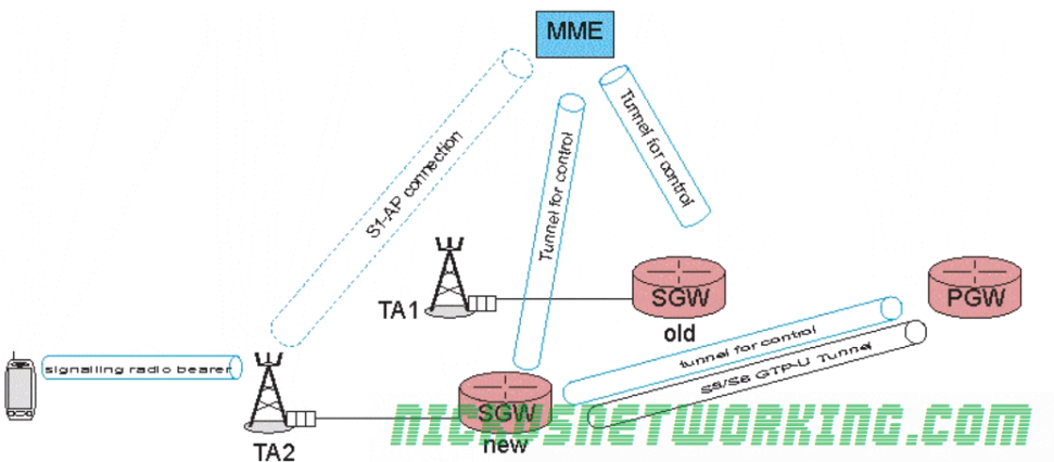
As the UE moves to the eNB in TA2 we need the MME to modify the tunnel from the P-GW to the S-GW to change it from connecting the P-GW to the old S-GW and instead connecting the P-GW to the new S-GW.
The MME establishes a new tunnel for control to the new S-GW, and sends a message to the new S-GW to modify the tunnel from the P-GW to the old S-GW to point to the new S-GW.
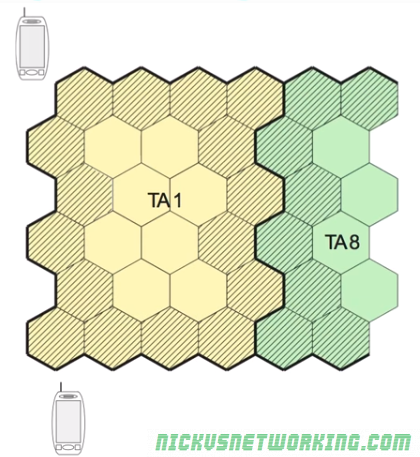
As we saw before larger Tracking Areas minimize the number of UEs between terminals to update their location.
The problem is the cells/eNBs on the edge of the Tracking Area have to handle almost all of the Tracking Area Update requests, to inform the network the UE has moved to a new TA.
The cells on the edges of the tracking area are shaded & handle the vast majority of the Tracking Area / Location Update messages
There’s an obvious imbalance between edge cells that handle almost all of Tracking Area Updates and the central cells inside a Tracking Area that handle very few many Tracking Area Update messages.
As we know we only have one radio interface, and sending Tracking Area Updates eats into our valuable radio resources that can’t be used to carry user data. Because of this users can experience a lower bit rate on edge cells.
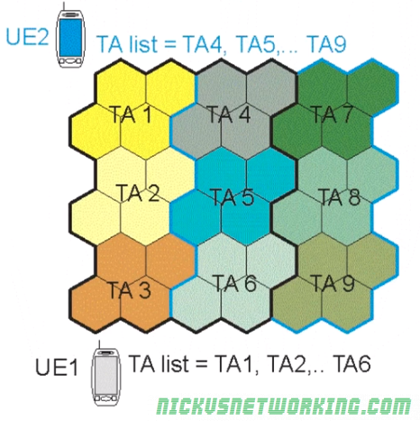
To get around this we group Tracking Areas together into Tracking Area Lists.
A Tracking Area List is provided by the network to the UE, and contains a list of Tracking Areas, so long as the UE stays within the list of Tracking Areas, there is no need for it to send a Tracking Area Update.
You might think this just makes our problem worse, as now at the edges of the cells in the Tracking Area List we have even more signaling traffic, the clever part comes from the fact the network gives out different Tracking Area Lists to different UEs.
In the example below we can see UE2 has a different Tracking Area List to UE1.
This means the cell edges are different for UE1 and UE2, which spreads the signaling load across Tracking Areas, so while UE2 will send a Tracking Area Update when it reaches the border from TA1 to TA4, UE1 will send a Tracking Area Update when it passes from TA6 to TA9.
The other limitation of this is now to reach a UE paging must be sent on all cells in the Tracking Area List.
As we saw with the Network Triggered Service Request, the network needs to know which eNB / cell the UE is currently being served by.
The UE knows which cell it should use as it’s always listening on the broadcast channel to know the received power levels of the nearby eNBs.
Paging
If our UE is in ECM IDLE state and the network needs to contact the UE, the eNB sends sends a Paging Request on the Beacon (Broadcast) Channel with the UE’s RNTI.
The UE is always listening on the Beacon Channel for it’s own RNTI, and when it hears it’s own RNTI it follows the process to come back from ECM_IDLE state to ECM_CONNECTED state.
For this to work the network needs to know which eNB to send the Paging request to.
For this to work our UE would need to inform the network each time it changes eNB, but, as we’ve touched upon several times, minimizing power consumption is a constant architecture constraint in LTE.
So if the UE has to transmit each time a UE moves to a different eNB / Cell, the UE power consumption would be high and the battery life of the UE would be low.
If we imagine driving along a freeway at speed, with each eNB serving an area of 1km, at 60kph, our UE would change cells every minute, and if the UE needs to transmit to let the network know it’s changing location, we’d be transmitting data every 60 seconds even if the UE is sitting in our pocket, all these transmissions would lead to lower battery life on the UE.
Tracking Areas
To work around the power wastage of each UE transmitting data to the network to let it know each time it changes eNB, 3GPP designers decided to group eNBs in the same geographic area into Tracking Areas or TAs.
This means instead of the network knowing exactly which eNB a UE is located in, it has it’s location down to a tracking area made up of several eNBs. (Tens to hundreds of cells per TA)
To go back to our freeway example, we might group all the eNBs along a freeway into one Tracking Area, all of which broadcast the ID of each eNB and the Tracking Area of each eNB.
As the UE moves from one eNB to another eNB in the same Tracking Area, there’s no need for the UE to send a Tracking Area Update message as it’s reamining in the same Tracking Area.
Tracking Area Update messages only need to be sent when the UE moves to an eNB in a different Tracking Area.
UEs can move from cell to cell inside TA1 without needing to update the network. Only when a UE moves from a eNB / cell in TA1 to TA2, does it need to send a Tracking Area Update message to the network.
Paging a Tracking Area
As the network knows the location of our UE down to a tracking area, when it comes time to Page a UE a Paging Request is simply sent from the MME to all eNBs in the Tracking Area that the UE is in.
This means the RNTI of the UE is broadcast out of all eNBs in that tracking Area, and the UE establishes connectivity once again with it’s nearest eNB.
As we discussed before when no data has been sent by a UE for a period of time the eNB will switch from an ECM-Connected state to an ECM-Idle state where there is no radio connection.
ECM-Connected state
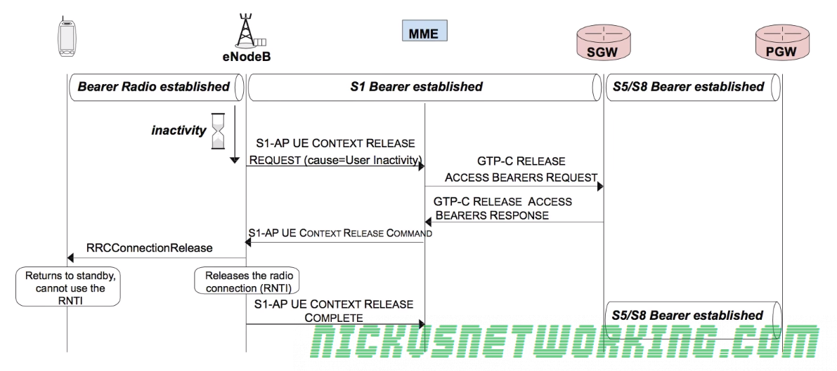
So let’s look at the release procedure.
When the transmission timeout (typically 10 – 30 seconds) has expired, meaning a user hasn’t sent data for that length of time, the eNB sends the MME a S1-AP UE Context Release Request with the cause of User Inactivity to denote why the change is being made.
The MME then sends a GTP-C message requesting release of the tunnel between the S-GW and the eNB (GTP-C Release request).
The S-GW sends back a GTP-C Release Access Bearers response, indicating it has cleared down the GTP tunnel between itself and the eNB,
The MME then sends a S1-AP UE Context Release Command to the eNB, and the eNB sends an RRCConnectionRelease which releases the RNTI assigned to that UE removing it’s radio resources.
Finally a S1-AP UE Context Release Complete is sent from eNB to the MME to let the MME know the process has completed.
Release procedure
At this stage the RNTI is no longer active so the UE cannot use the RNTI and therefore cannot be assigned radio resources.
The UE is now in ECM_Idle mode, however as it still has an IP Address allocated and can be bought back it’s in EMM_Regsitered mode.
States
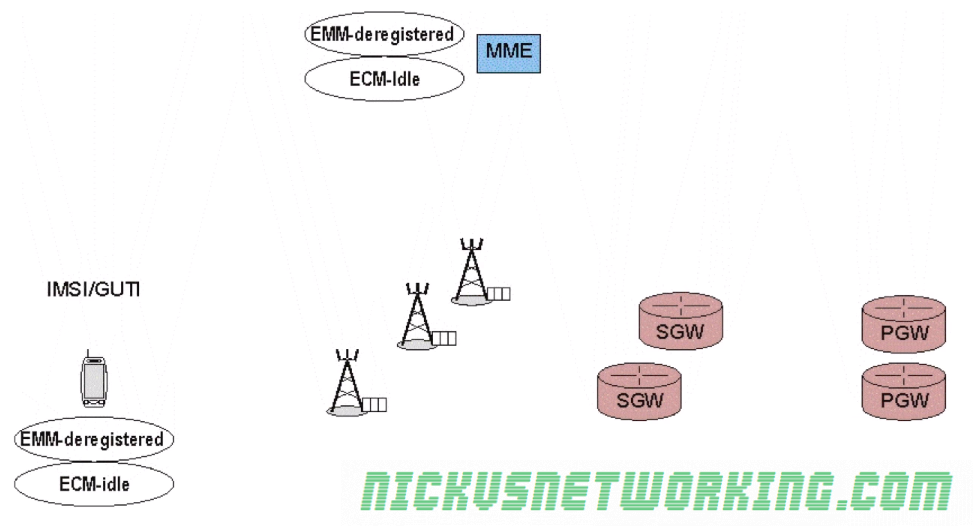
EMM-Deregistered State
UE is disconnected from the network with no radio resources and does not have an IP Address
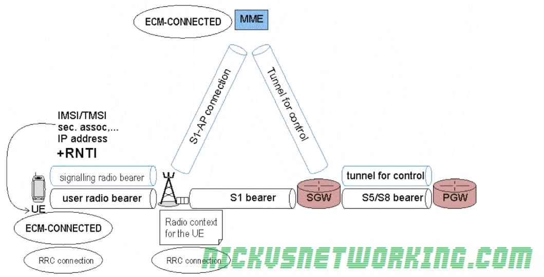
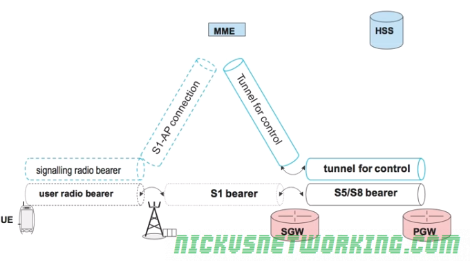
EMM-Registered & ECM-Connected
UE is connected to the network with an IP address
Radio resources (RNTI allocated)
Location of the UE known
All tunnels & connections established
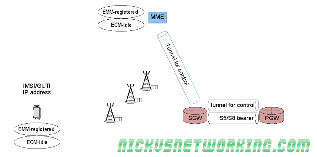
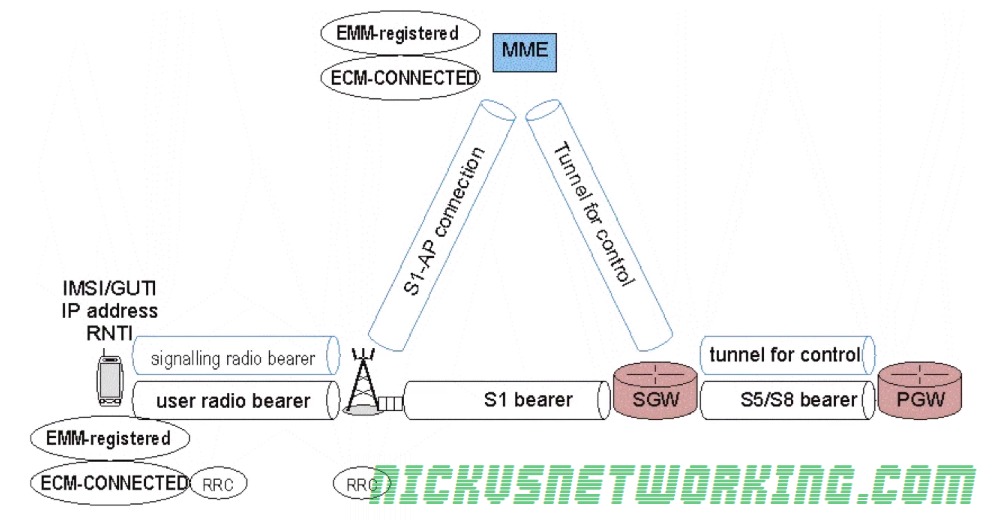
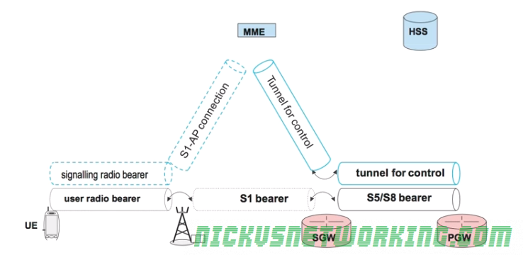
EMM-Regsitered & ECM-Idle
UE has an IP address & appears to be connected
No radio resources (RNTI) currently in use
No tunnels or connection from the eNB to the S-GW & MME.
Tunnel between S-GW and P-GW and the tunnel between the MME and S-GW
A relative location (tracking area) of the UE is available
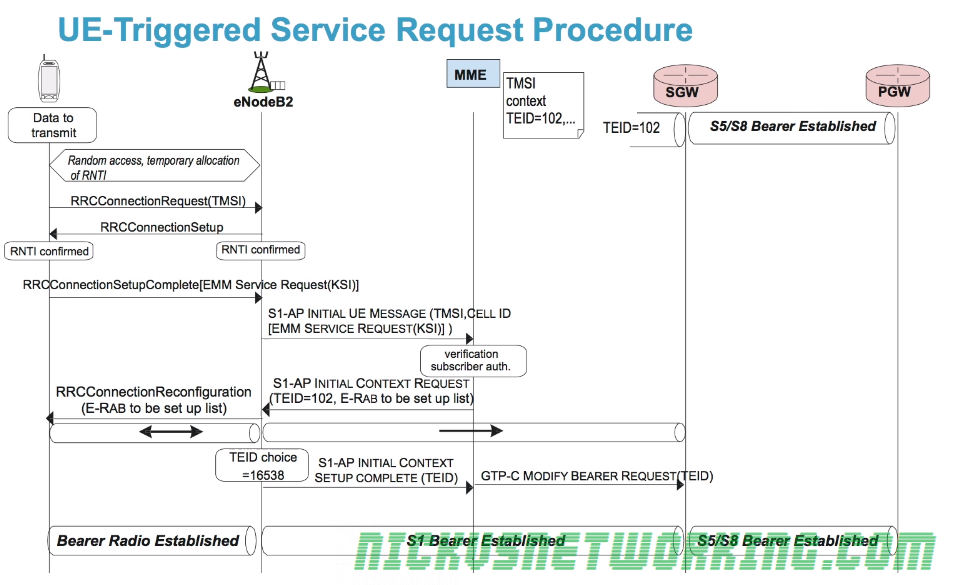
As we just saw when a terminal moves to ECC-Idle while in EMM-Registered state, it releases it’s radio resources, so what happens when the UE needs to send / receive data again?
UE is disconnected from Radio Resources (ECM-Idle & EMM Registered)
While one option could have been to go through the full attach procedure again when the UE is triggered, the 3GPP team wanted the re-connection process to be as fast as possible.
As we saw in the last post we don’t drop the S-GW <-> P-GW tunnel, which saves time on re-establishing a connection. The S1 tunnel is also not completely released; the TEID value from the S-GW end of the tunnel is saved by the MME so it can be reused by the new tunnel when the UE reconnects, without needing to inform the S-GW.
One of the common themes we cover over and over in the 4G discussion is the desire to preserve energy on the UE RF side of things, to extend battery life as much as possible.
The 3GPPs requirements for LTE also included the smallest round trip times, defining less than 5 ms in unload condition, so traffic to the UE must be routed as quickly as possible.
Mobiles are by their very nature, mobile.
This requires UEs to constantly monitor the RF conditions and the signal measurements from different base stations so the UE can determine if it’s time to handoff to another cell due to going further from one eNB and closer to another, or another eNB offering better RF conditions (Strong signal etc).
This requires regular exchanges of messages and checks, but this would take a lot of energy and eat up battery usage.
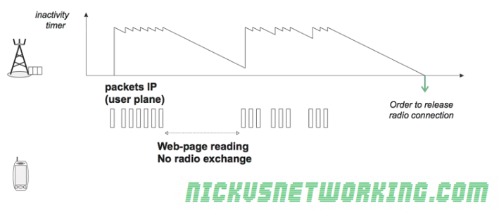
Instead we avoid maintaining the radio connection all the time with the aid of an inactivity timer on the eNB.
For as long as user data is flowing over the air interface the connection is maintained, for example web browsing, the inactivity timer is constantly reset as traffic flows.
However when the eNB detects no packets sent or received by the UE the timer starts counting down from it’s set value.
When the inactivity timer reaches 0 the RRC Connection is released and the UE no longer has an RNTI.
The UE is still listening to an eNB, it’s just not sending data to it it and visa-versa.
As the radio bearer has been removed the UE the S1-AP and S1-UP bearers between the eNB and the MME and the eNB and the S-GW respectively, can be torn down.
This means the MME is no long sure of exactly which eNB the UE is listening on.
This is referred to as ECM_IDLE state as there is no radio connection, and the network is unaware of the precise location of the UE.
An ECM_ACTIVE state is the state when the UE is connected to an eNB with an RNTI and it’s inactivity timer has not reached 0.
The dotted line bearers shown in the image above frequently change between active and inactive based on the ECM_ACTIVE / ECM_INACTIVE state of the bearers.
EPS Mobility Management (EMM) has two states – EMM-Registered (UE reachable) and EMM-Deregistered (UE not reachable).
A UE is in the deregistered state when it is not rechable, for example not currently powered up or in flight mode.
The MME memorizes the state of each UE and it’s context elements such as it’s most recent GUTI, IMSI, security parameters etc.
Attach Procedure
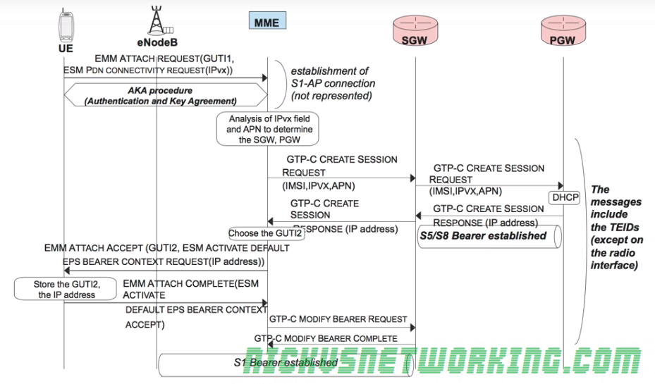
To attach to the network a UE sends an EMM Attach Request with it’s most recent GUTI to the MME.
In the same request the UE also includes an ESM PDN Connectivity Request to gain access to the external networks.
The Authentication & Key Agreement procedure is followed between the UE and the MME/HSS to authenticate the network and the subscriber.
One this is done the MME looks at the connectivity requested and the APN of the subscriber, the MME then selects a Serving-Gateway and Packet-Gateway based on the APN.
The MME then sends a GTP-C Create Session Request along with the connectivity requested (IPv4/6), APN and IMSI of the subscriber and it’s allocated TEID for this tunnel to the S-GW.
The S-GW also sends a GTP-C Create Session Request along with the connectivity requested (IPv4/6), APN and IMSI of the subscriber to the P-GW, along with the S-GW’s allocated TEID for this tunnel too.
The P-GW then sends a GTP-C Create Session back to the S-GW containing it’s TEID and it also includes the IP Address to be allocated to the UE.
A GTP session is now setup between the P-GW and the S-GW for this bearer, with the TEID values added to the TEID management tables on both devices. This GTP tunnel is referred to an S5 (home) or an S8 (roaming) Bearer in 3GPP parlance.
Another GTP-C Create Session message with it’s own TEID is also sent from the S-GW to the MME.
The MME, S-GW and P-GW now each know TEID for each of the 2 tunnels setup (MME<->S-GW, S-GW<->P-GW) so have what they need to fill their TEID management tables.
When the MME recieves the GTP-C Create Session with the IP Address for the UE it sends an EMM Attach Accept and a EPS Bearer Context Setup Request containing the IP Address the P-GW allocated to the UE to the UE itself.
The UE stores the allocated IP and sends an acknowledgement to the MME in the form of an EMM Attach Complete message back to the MME.
The MME sends a GTP-C Modify Bearer Request which transfers the bearer setup between MME and SGW and modifies it to be between the SGW and the eNB.
The S-GW sends back a GTP-C Modify Bearer Complete message and modifies the GTP tunnel to be between the SGW and the eNB. A S1 bearer is now established for carrying user data from the eNB to the SGW.
Once this procedure is complete the UE is now in the EMM Registered State meaning it is known to the MME, it has a security association and has an IP Address.
The S-GW and the P-GW also stores the TEIDs for the UE.
Detach Procedure
When a UE detaches from the network (for example it powers down), the network must release all the tunnels for that UE, the MME state must be updated to EMM Deregistered and the MME must also keep a record for the last GUTI and security keys,
To detach from the network the UE sends a RLC UL Information Transfer message containing an EMM Detach Request which includes it’s current GUTI.
As soon as the UE recivers confirmation from the eNB the UE can power down, but the eNB must inform the network of the disconnection so the resources can be released.
The eNB sends a S1Ap Uplink NAS Transport message containing a EMM Detach Request with the UE’s GUTI to the MME.
The MME can then release the security context,
The MME then sends a GTP-C Delete Session Request to the S-GW.
Upon recipt of this request the S-GW requests the P-GW tears down it’s tunnel between the P-GW and S-GW (aka the S5/S8 Bearer) by sending it’s own GTP-C Delete Session Request to the P-GW.
Once the S-GW has confirmation the tunnel has been taken down (In the form of a GTP-C Delete Session Response) the S-GW sends a GTP-C Delete Session Response to the MME.
The MME must signal to the eNB it can release the RNTI and the radio resources. To do this it sends a S1-AP UE Context Release Command which releases the radio bearers and tears down the S1-UP bearer between the eNB and the S-GW.
The eNB then sends a S1-AP UE Context Release Completeto the MME.
Finally the MME sends a Diameter Notification Request (PGW and APN Removed) to the HSS to update the HSS of the user’s status, the HSS signals back with a Diameter Notification Answer and the HSS knows the user is no longer reachable.
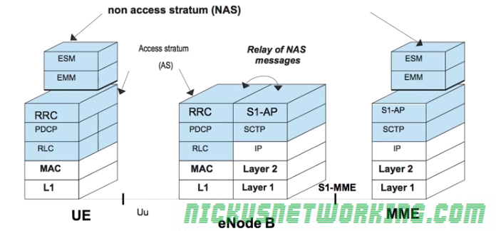
The LTE architecture compartmentalises the roles in the mobile network.
For example the eNB concentrates on radio connection management, while the MME focuses on security and mobility.
Non Access Stratum (NAS) messages are exchanged between the terminal and the MME.
Access Stratum (AS) messages are exchanged over the air between the UE and the eNB. It contains all the radio related information.
The eNB must map the NAS messages from an MME to a LCID and RNTI and transmit them over the air, and vice-versa. The eNB forwards this data without ever analyzing it.
To handle this load the requirements of each subscriber for the MME must be as minimal and simple as possible so as to scale easily.
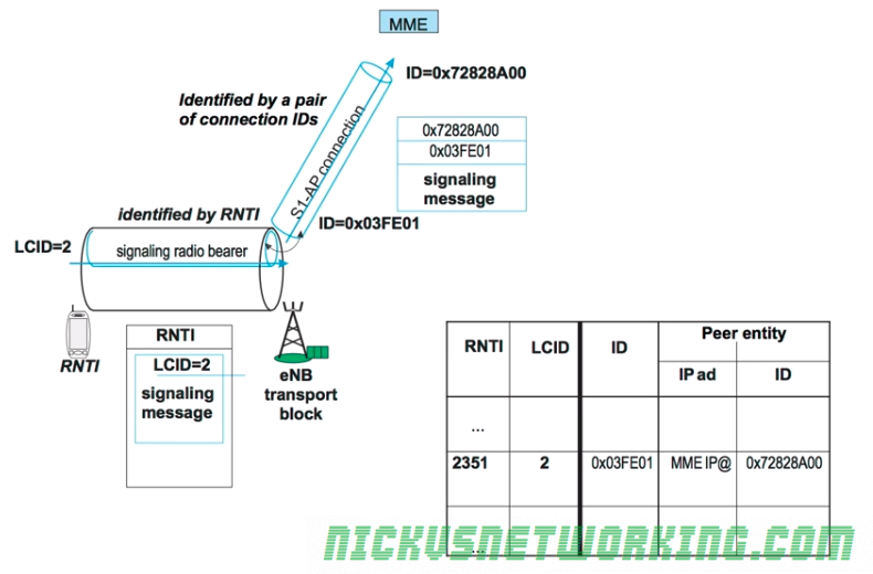
For each UE in the network a connection is setup between the UE and the MME.
This is done over the S1-AP’s Control Plane interface (sometimes calls S1-Control Plane or S1-CP) which carries control plane data to & from the UE via the eNB to the MME.
S1-CP is connection-oriented, meaning each UE has it’s own connection to the MME, so there are as many S1-CP connections to the MME as UE’s connected.
Each of these S1-CP connections is identified by a pair of unique connection IDs. The eNB keeps track of the connection IDs for each UE connected and hands this information off each time the UE moves to a different eNB.
The eNB keeps a lookup table between the RNTI of the UE and the LCID – the Logical Channel Identifier. This means that the eNB knows the sent and received ID of the S1-CP connection for each UE, and is able to translate that into the RNTI and LCID used to send the data over the air interface to the UE.
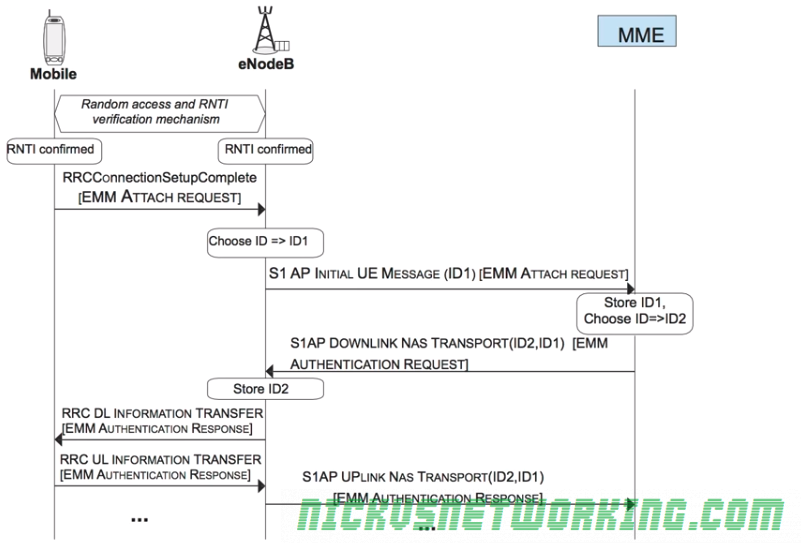
Once the RNTI is confirmed by both the eNB and the UE, a EMM Attach Request, which is put into an RRC Message called RRCConnectionSetupComplete.
The eNB must next choose a serving MME for this UE. It picks one based on it’s defined logic, and sends a S1-AP Intial UE Message (EMM Attach Request) to the MME along with the eNB’s connection identity assigned for this connection.
The MME stores the connection identity assigned by the eNB and chooses it’s own connection identity for it’s side, and sends back an S1AP Downlink NAS Transport response with both connection identities and the response for the attach request (This will be an EMM Authentication Request).
The eNB then stores the connection identity pair and the associated RNTI and LCID for the UE, and forwards the EMM Authentication Request to the RNTI of the UE via RRC.
The UE will pass the authentication challenge input parameters to the USIM which will generate a response. The UE will send the output of this response in a EMM Authentication Responseto the eNB, which will look at the RNTI and LCID received and consult the table to find the Connection Identifiers and IP of the serving MME for this UE.
When a new tunnel is setup between two nodes, GTP-C will be used to setup the tunnel and the both ends of the tunnel will allocate a their own locally unique TEID to the tunnel.
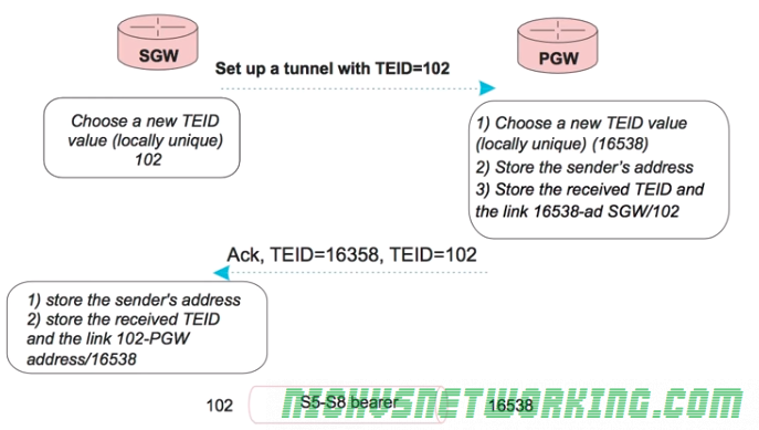
Let’s take a look at setting up a GTP tunnel between a S-GW and a P-GW, initiated by the S-GW.
The process will start with the S-GW sending the P-GW a GTP-C tunnel establishment request and include the TEID the S-GW has allocated for it’s end of the tunnel (using TEID 102 in this example), sent from the S-GW to the P-GW.
The P-GW will receive this packet. When it does it will allocate a new TEID for this tunnel for it’s side (In this case it’s 16538), store the sender’s address and received TEID, and link local TEID 16538 with S-GW/102.
An ACK is sent from the P-GW to the S-GW with both TEID values.
Finally the S-GW stores the senders’ address, the received TEID and the link 102-PGW address 16538.
Now the exchange is complete the S-GW and the P-GW each know the TEID of it’s local side of the tunnel, and the remote side of the tunnel.
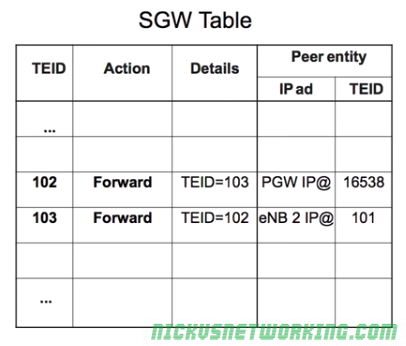
TEID Management Tables
After GTP tunnels are setup a management table is populated defining the forward rules for that traffic.
For example a packet coming in on TEID 103 would, according to the table forward to TEID 102. TEID 102 sends traffic to the P-GW’s IP using remote TEID 16538.
The same rules for uplink are applied for downlink.
Each tunnel has pair of TEIDs a local TEID and a remote TEID.
Because it’s such a simple table it can be updated very easily and scales well.
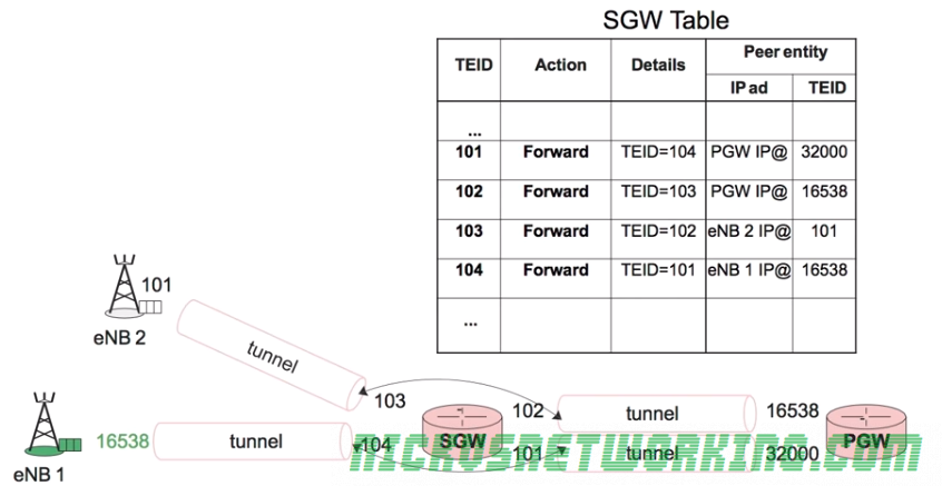
Different QoS parameters can be assigned to each tunnel, called a data bearer.
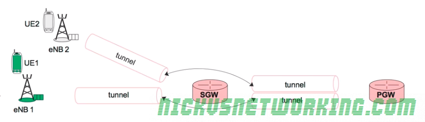
As we’ve talked about traffic to and from UEs is encapsulated in GTP-U tunnels, with the idea that by encapsulating data destined for a UE it can be routed to the correct destination (eNB serving UE) transparently and efficiently.
As all traffic destined for a UE will come to the P-GW, the P-GW must be able to quickly determine which eNB and S-GW to send the encapsulated data too.
The encapsulated data is logically grouped into tunnels between each node.
A GTP tunnel exists between the S-GW and the P-GW, another GTP tunnel exists between the S-GW and the eNB.
Each tunnel between the eNB and the S-GW, and each tunnel between S-GW and P-GW, is allocated a unique 32 bit value called a Tunnel Endpoint Identifier (TEID) allocated by the node that corresponds to each end of the tunnel and each TEID is locally unique to that node.
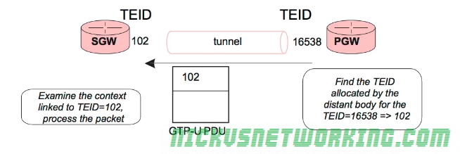
For each packet of user data (GTP-U) sent through a GTP tunnel the TEID allocated by the receiver is put in the GTP header by the sender.
The destinations of the tunnels can be updated, for example if a UE moves to a different eNB, the tunnel between the S-GW and the eNB can be quickly updated to point at the new eNB.
If the UE moves to a different eNB only the tunnel between the S-GW and the eNB needs to be updated
Each end of the tunnel is associated with a TEID, and each time a GTP packet is sent through the tunnel it includes the TEID of the remote end (reciever) in the GTP header.
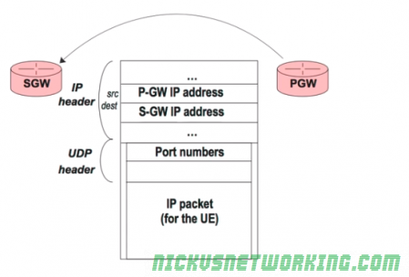
When a packet arrives from an external network, like the internet, it is routed to the P-GW.
The P-GW takes this packet and places it in another IP packet (encapsulates it) and then forwards the encapsulated data to the Serving-Gateway.
The S-GW then takes the encapsulated data it just recieved and sends it on inside another IP packet to the eNB.
The encapsulated data sent from the P-GW to the S-GW, and the S-GW to the eNB, is carried by UDP, even if the traffic inside is TCP.
Communication between these elements can be done using internal addressing, and this addressing information will never be visible to the UE or the external networks, and only the P-GW needs to be reachable from the external networks.
This encapsulation is done using GTP – the GPRS Tunneling Protocol.
Specifically IP traffic to and from the UE is contained in GTP-U (User data) packets.
The control data for GTP is contained in GTP-C packets, which sets up tunnels for the GTP traffic to flow through (more on that later).
To summarize, user IP packets are encapsulated into GTP-U packets, which are a transported by UDP between the different nodes (S-GW and eNB)
In a fixed network, if I were to connect my laptop to my network at home, I’d get a different address to if I plug it in at work.
In a mobile network UEs are often moving, but we can’t keep changing the IP address – that would lead to all sorts of issues.
The UE must maintain the same IP address, at least for the duration of their session.
Instead the IP address of a UE is allocated by the P-Gateway (P-GW) when the UE attaches.
The IP the P-GW allocates to the UE is in a subnet managed by the P-GW – that IP prefix is associated with the P-GW, so traffic is sent to the P-GW to get to the UE.
Therefore all traffic destined for the UE from external networks will be sent to the P-GW first.
Because the UE is mobile and changing places inside the network, we need a way to keep the UE’s IP even though it’s moving around, something that by default TCP/IP networks don’t cater for very well.
To achieve this we use a technique known as encapsulation where we take the complete IP packet for the UE, and instead of forwarding it on to the UE on a Layer 3 or Layer 2 level, we bundle the whole packet up and put it inside a new IP packet we can forward on anywhere regardless of what’s insude, until it gets to the eNB the UE is on when it can be unpacked and sent to the UE, which is unaware of all the steps / hops it went through.
The concept is very similar to GRE to a VPN (PPTP, IPsec, L2TP, etc) where the user’s IP packets are encapsulated inside another IP packet.
We encapsulate the data using GTP – GPRS Tunneling Protocol.
From a Layer 3 perspective the fact the contents of the GTP packet (another IP packet) is irrelevant, and it’s just handled like any other IP packet being sent from the P-GW to the S-GW.
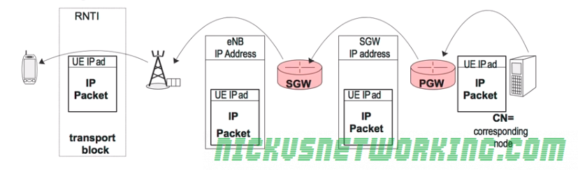
Getting traffic to the UE
When a packet is sent to the UE’s IP Address from an external destination, it’s first sent to the P-GW, as the P-GW manages that IP prefix.
The P-GW identifies the packet as being destined for a UE, so it encapsulates the entire packet for the UE, by wrapping it up inside a GTP packet.
UE’s IP Packet encapsulated by the P-GW and sent to the IP of the S-Gw
The P-GW then forwards the GTP packet to the serving Serving-Gateway (S-GW)’s IP Address, so the S-GW can forward it to the eNB to get to the UE.
(The P-GW forwards the traffic to the S-GW so the S-GW can get it to the correct eNB for the UE, the reason for having two nodes to manage this is so it can scale better)
Once the traffic gets to the the eNB serving the UE, the eNB de-encapsulates the data, so it’s now got an IP packet with the destination IP of the UE.
It takes the data and puts it onto a transport block sent to the specific RNTI of the UE.
The hops between the UE and the P-GW are transparent to the UE – it doesn’t see the IP Address of the eNB or the S-GW, or any of the routers in between.
As the traffic is point to point headers vary vary little so is predictable and can be compressed efficiently.
For a VoLTE medea stream a 40 byte IPv6 header, 8 byte UDP header, 12 byte RTP header and 30 bytes of RTP data.
This means that we have 60 bytes of headers and only 30 bytes of data, which is a very inefficient use of resources, so by compressing this data we can shrink this substantially.
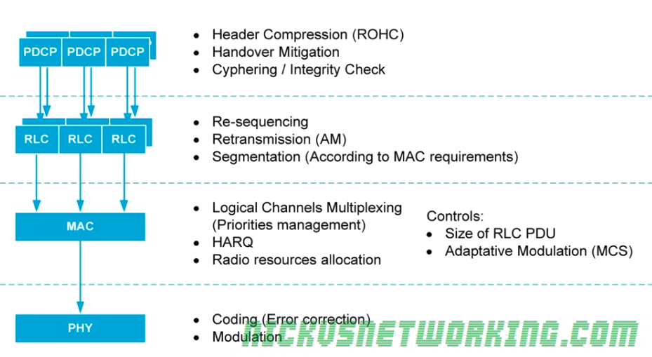
Handover Mitigation
When handing over between NodeBs on previous 3GPP RANs packet loss and reordering was common during handovers between NodeBs.
E-UTRAN specs have minimized this as much as possible, the handing off eNB can transfer information using PDCP about data to be transferred to the UE to the eNB the UE is handing over too.
Security
As the radio link is particularly vulnerable to eavesdropping, PDCP offers another independent ciphering and integrity control mechanism to verify data is not modified / intercepted.
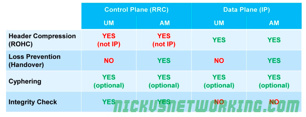
Usage of PDCP Functionality
Not all these functionalities are used for all types of traffic, as shown in the table below.
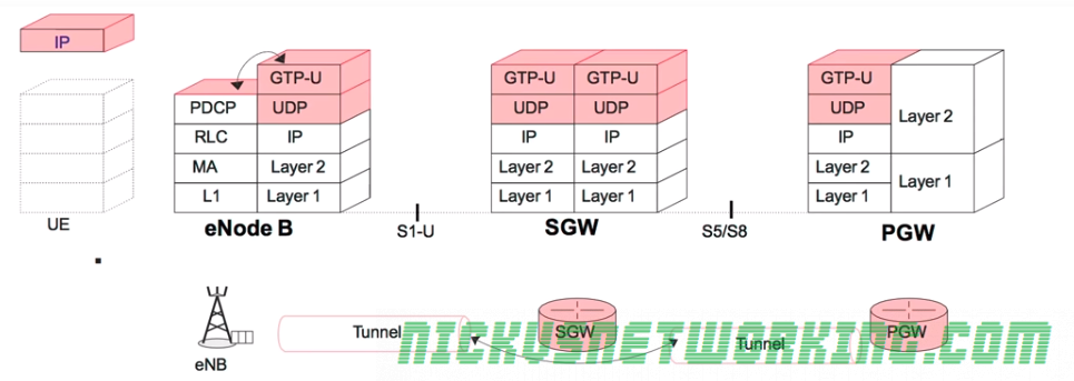
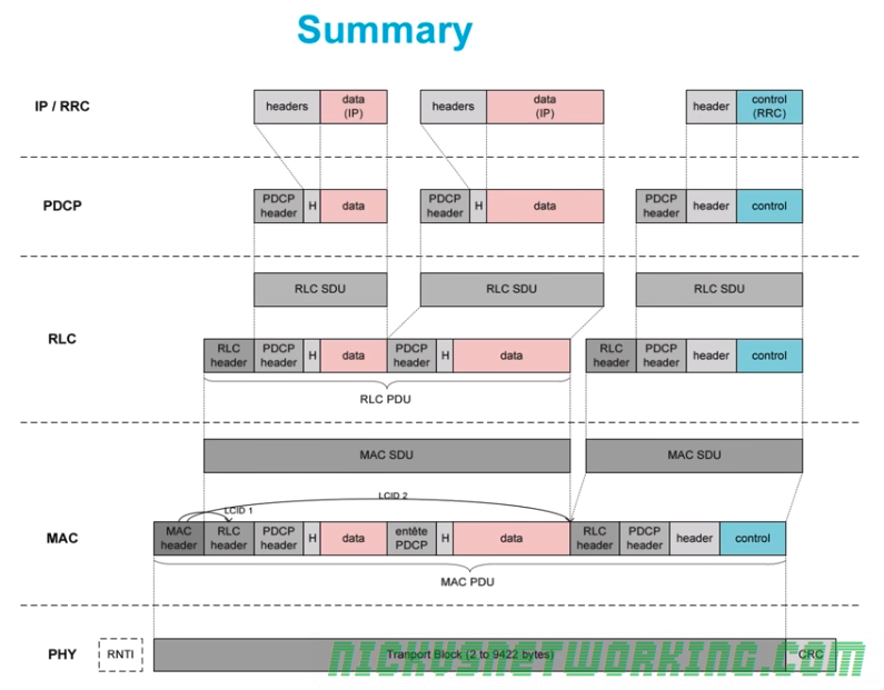
Recap of Radio Interfaces
PDCP is discussed in this post, interfacing the radio interface with the core network.
A summary of the hierarchy is shown here with user data in pink and control data in blue:
The RNTI is shown in a dotted box as the RNTI is not transmitted as a header on the transport block but is logically associated with the transport block thanks to the allocation table.
The problem is when it comes time to add a new UE to an eNB, the UE needs to be allocated a resources to be allocated a RNTI so it can request / be allocated resources.
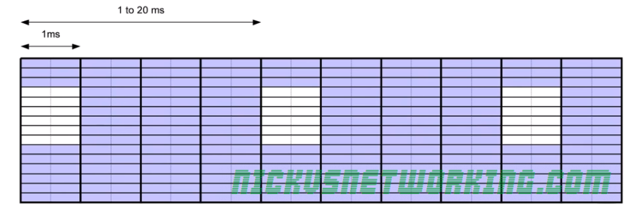
In the uplink a group of resources is reserved so any new UE can indicate it’s presence and be assigned an RNTI, so it can go on to request & be allocated resources.
This is done on the Physical Random Access Channel (PRACH), made up of 6 resource blocks, and occurs every 1-20ms depending on what the operator has configured.
Access to the PRACH is by CDMA (Code Division Multiple Access). Without going into the mechanics of CDMA the important thing to note is that on CDMA two transmissions can occur at the same time and as long as they are each using a different one of CDMA’s 64 Codes the eNB will be able to distinguish between the two transmissions.
When attempting to associate the UE will send a CDMA symbol with one of the 64 CDMA sequence codes across all 6 resource blocks. As we discussed the eNB will still be able to determine the code used even if multiple UEs were transmitting at the same time each hoping to associate with the eNB.
UE Attach and RNTI Assignment
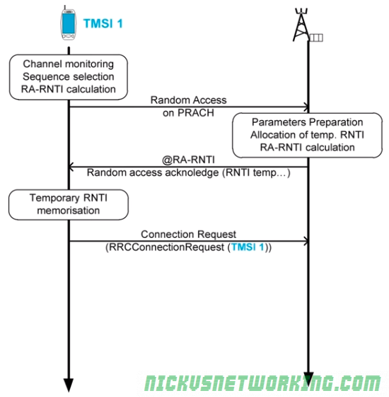
The UE begins by listening to the eNB to identify when the Physical Random Access Channel (PRACH)is scheduled.
Once the UE knows when the PRACH is going to be it transmits one of the 64 possible CDMA codes on the PRACH in all 6 of the resource blocks in the Random Access Channel.
The eNB detects the transmission and which one of the 64 CDMA codes was used by the UE wishing to attach, and the eNB assigns it an RNTI.
At this point only the eNB knows the RNTI, it needs to let the UE know it’s assigned RNTI so it can start scheduling.
The eNB creates a new identifier RA-RNTI or Random Access – RNTI. This is calculated using the CDMA code used by the UE in it’s transmission on the PRACH and the RNTI to be assigned.
The eNB then allocates a resource for that RNTI so the UE can send a response back in the form of a Connection Request containing the TMSI.
The eNB then echos back the connection request on the channel allocated to the RNTI.
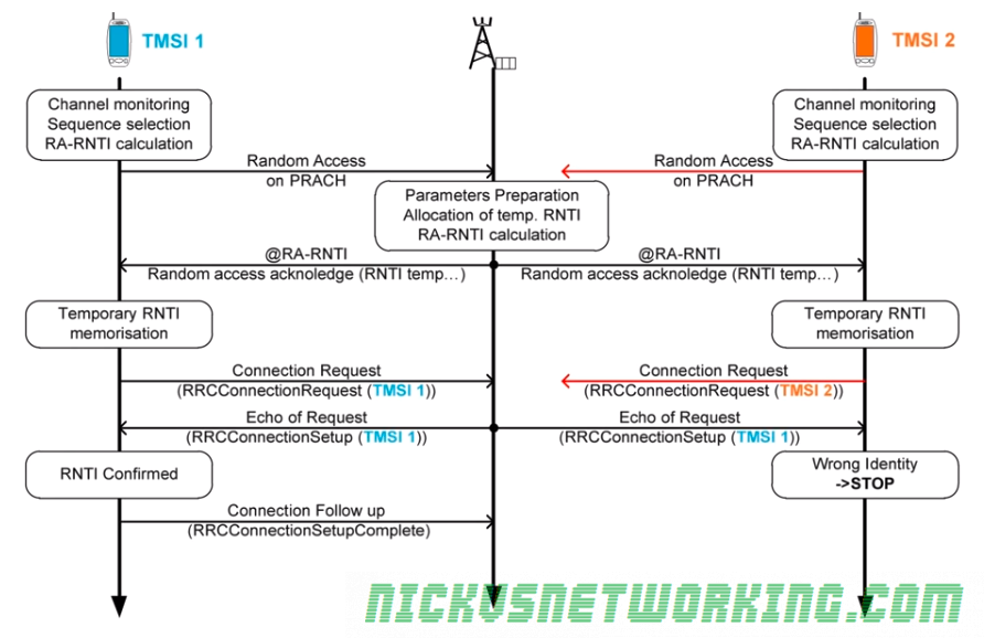
The echo procedure means if two UEs happened to use the same CDMA Code and both believed they were the owner of the RNTI assigned by the eNB, the eNB would either have received only one of the responses, in which case the other would detect the wrong identity in the echo and start the random access procedure again, or both would be lost and both would start the random access procedure again, as shown below:
As we can see the eNB recieved TMSI1’s Connection Request, and sent back the echo, TMSI one confirmed it and continued the setup procedure, while TMSI2’s Connection Request was not received by the eNB and it knows this beacuse the echo did not contain it’s TMSI. TMSI2 detects thew wrong identity and stops that process and starts the random access procedure again.
The Radio Link Control (RLC) layer sits above the MAC layer and can manage:
Re-sequencing of blocks held up by HARQ
Concatenates / segments messages to fit into the size defined by the MAC layer
Re-transmits lost blocks (independent of ARQ)
These functions are set out and managed based on which of the 3 RLC Modes used based on QoS requirements of the traffic type.
RLC Modes
RLC has 3 services or modes that can be used depending on the type of data transmitted:
Transparent Mode (TM)
Does not offer any RLC features / services
Can only be used for short messages (As no segmentation to fit MAC requirements)
Mainly used for signaling messages
Unacknowledged Mode (UM)
Re-Sequences data if received out of order
Segments data according to MAC needs / limitations
Low latency but no re-transmission on the RLC layer
Suitable for VoLTE / real time communications
Does not re-transmit lost packets
Acknowledged Mode (AM)
Like UM but adds re transmission of lost packets
Higher latency but more reliable
Suitable for web browsing, file transfer, etc.
Upon valid receipt of a message the receiver sends an ACK on the data channel.
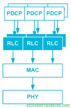
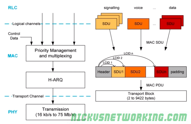
Several different RLC modes/services can be used at the same time by a single UE, as we saw in the last post:
The MAC layer takes packets from each of the different RLC streams and packs them into MAC SDUs.
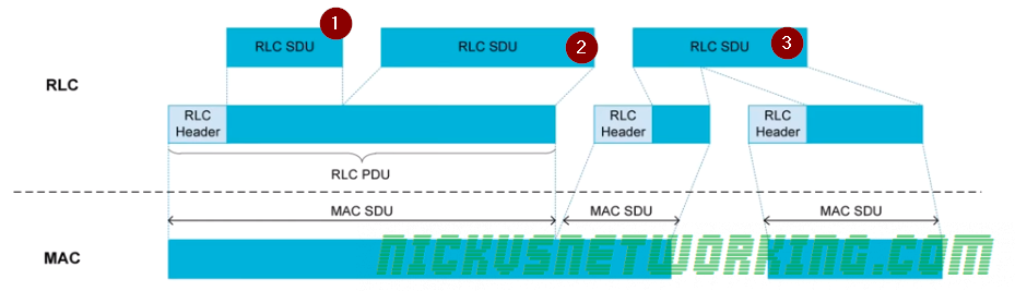
Here we can see 3 different RLC SDUs being packet into MAC SDUs.
RLC SDU 1 is packed into the a RLC PDU along with RLC SDU2. These two are concatenated together. RLC also adds a header to delineate the start of RLC SDU 1 and the start of RLC SDU 2.
The header allows the receiver to determine where each RLC SDU starts and ends and the sequence number of each RLC SDU.
Part of RLC SDU 3 is also packed into the first RLC PDU, and the second part is packed into the next RLC PDU. RLC is said to have segmented or fragmentedthis message as it splits it across multiple RLC PDUs for transmission. Again the RLC PDU adds headers to define that the data it contains is split across multiple RLC PDUs.
The MAC layer (Media Access Control) handles error correction, and performs multiplexing of services to the same UE at the same time (multiplexing).
Automatic Repeat Request (ARQ)
When data is sent a CRC (Cyclic Redunancy Check) is added, containing a checksum equivalent of the data contained in the message.
The receiver runs the same CRC calculation on the data, and if the CRC value is not equal to the CRC value it received it knows the data is not correct/complete.
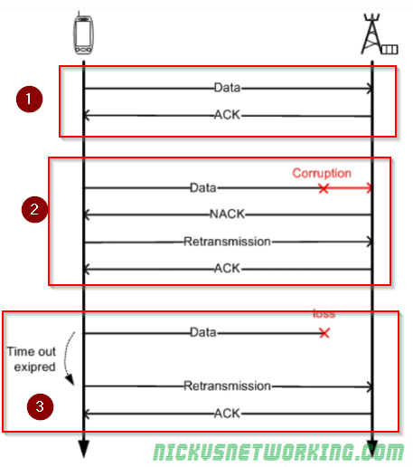
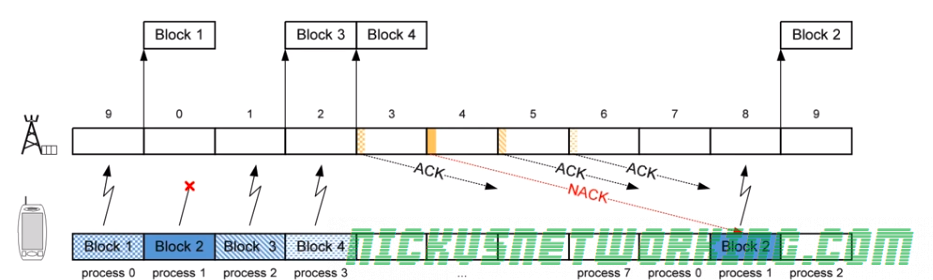
There are 3 scenarios shown below:
Scenario 1 – Data is sent and the CRC calculated by the sender matches the CRC calculated by the reciver. An ACK is sent to confirm the data was received correctly.
Scenario 2 – Data is sent and the CRC calculated by the sender does not match the CRC calculated by the receiver. The receiver sends a NACK (Negative Ack), The sender sends the data again, the CRC this time matches, so an ACK is sent to confirm the data was received correctly.
Scenario 3 – Data is sent by not ACK or NACK was received. This could mean the data was not received, or the ACK/NACK was not received. The sender then sends the message again. This process is repeated a set number of times after which if no response is received the sender gives up.
Acknowledgement
This technique is called Send and Wait ARQ, because the sender must send the data and wait for an ACK/NACK, and will automatically request re-transmission.
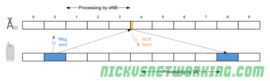
Because CRC may take some time to calculate the ACK/NACK is given time to process by the receiver and the ACK/NACK is sent 4ms after it was received.
If a NACK is received the data is re-transmitted 4ms after receipt of the NACK.
This means all up it takes up to 8ms (8 subframes) to send the data, wait for the response and send again if needed. During this time no other data would be sent.
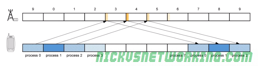
As you can imagine this isn’t a particularly efficient use of time or resources, so the EUTRAN specs define 8 Send and Wait processes in parallel.
While the first process is blocked waiting for an ACK/NACK, another process can transmit. This is called Parallel Send and Wait.
The problem with this is it can lead to data being received out of sequence, as if data is sent and a re-transmission is needed (NACK received by sender) that data will be received after the data sent 8 frames after it.
Here we can see Block 2 was lost, a NACK was sent and a re-transmission occurs 8 subframes later, long after Block 3 and Block 4 were received.
The MAC layer does not deal with re-sequencing, this is managed by the RLC layer above the MAC layer.
Hybrid ARQ
LTE relies on Hybrid ARQ. To increase redundancy and increase the possibility of decoding a corrupted message correctly.
We talked about coding – sending multiple copies of the same data and comparing them to find the common features that would indicate correct data, Hybrid ARQ functions in much the same way.
To increase error correction performance the receiver keeps the invalid/corrupt messages it sends a NACK for, so it can compare it to the re-transmitted version and hopefully correctly decode the message even if the re-transmission is corrupted.
It is called Hybird because the MAC layer has to communicate to the physical layer to let is know this is a re-transmission and not a new transmission.
Multiplexing on the MAC Layer
You may use your smartphone (UE) for a voice call while looking up something online and getting push notifications, while these are 3 distinct streams of data, there is only one stream of data to and from the eNB <-> UE.
These different types of data all need to be combined into one “pipe” between the eNB and UE, this is known as multiplexing.
The RLC layer has multiple types of data arranged in logical channels, but this data has to be put into a MAC PDU and sent over the air.
In the standard networking model, data in an upper layer is called SDU “Service Data Units”, and data in a lower layer is called a PDU “Protocol Data Units”.
To form the transport blocks the MAC layer must take each of the SDUs from the RLC layer, and put it into the transport block, as show in the image above.
The MAC header contains the delineation of what data is for which SDU on the RLC layer.
To inform UEs of which resources are allocated to it, the eNB regularly publishes Allocation Tables with this information.
Resources are allocated dynamically, by the eNB to all the UEs it is serving.
Because the eNB manages all the resources, the eNB must inform the UEs which resources are allocated to which UEs.
This is broken into two functions:
A UE must be able to be informed it’s going to receive data (downlink) and be allocated the resources for it.
A UE must be able to request resources from the eNB to send data (uplink) and be allocated resources for it.
The eNB manages all resource allocation, for downlink and uplink, when they are needed. This is done through an allocation table published by the eNB every subframe (1ms).
There are two allocation tables – One for uplink, one for downlink.
Addressing on the Radio Interface – RNTI
As an allocation table needs to allocate resources to each UE it needs a way to address them.
GUTI, IMSI, TMSI etc, are all too long (allocation tables are published every subframe so need to be a small as possible).
Instead for addressing in the allocation tables as RNTI – Radio Network Temporary Identifier is issued by the eNB to each UE it is serving, the RNTI is issued by the eNB and only valid for that cell, if the user moves to another cell served by another eNB another RNTI is allocated by that eNB.
The RNTI is 16 bits long, meaning it can store 65,536 decimal values. (65,536 UEs)
Allocation on Downlink
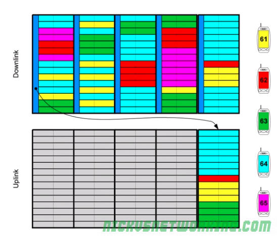
Resource allocation for the downlink is managed by the eNB, which publishes allocation tables every subframe defining which resource blocks are allocated to which UE.
The resource blocks contains the RNTI of each UE to receive data and the resource blocks it’s data will be contained in.
Each UE listens for the allocation tables published in each subframe, and if the UE sees it’s own RNTI in the allocation table it listens on the resource blocks allocated to it.
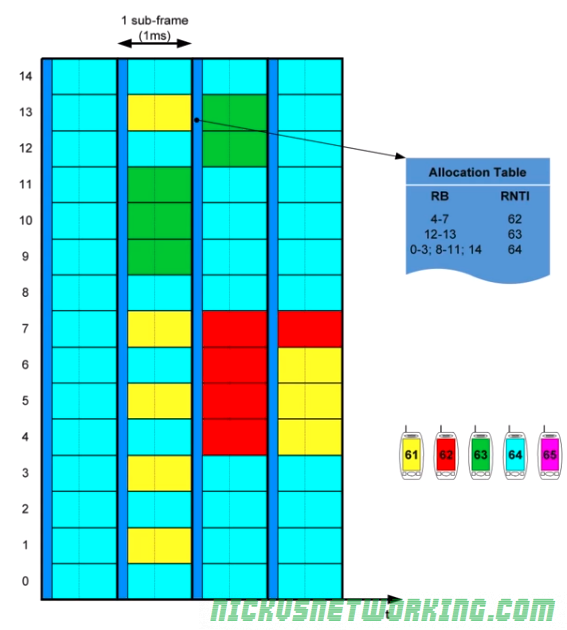
In the example above we can see the allocation table in the dark blue colour, published every 1ms (aka every subframe).
In this example the UE that has been assigned RNTI 63 (represented in green) has got resource blocks 12 & 13 assigned to it, so will listen on 12 and 13 to get it’s downlink data.
Because UEs only listen for the allocation tables and the resource blocks assigned to them, it leads to power savings on the UE as they don’t all need to listen / decode to all resource blocks. Power savings on the UE translate to better battery efficiency.
The UE with RNTI 61 for example, does not get allocated any resource blocks in the downlink in the example allocation table, so it listens for the allocation table and then goes into standby mode until the next allocation table is published.
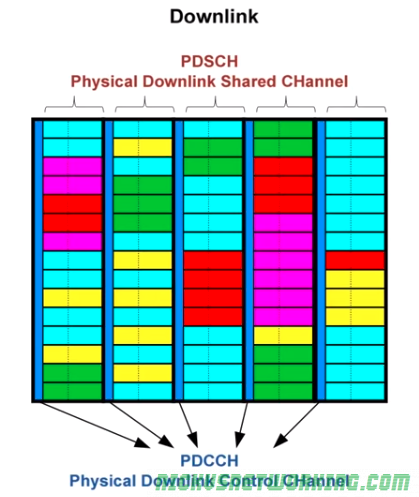
The allocation tables are contained in the Physical Downlink Control Channel (PDCCH) a channel used only by the eNB to broadcast resource allocation tables and control data.
The actual downlink data for each UE is contained in the Physical Downlink Shared Channel (PDSCH)
Allocation in the Uplink
Allocation in the uplink is similar to allocation in the downlink, however there are some important differences.
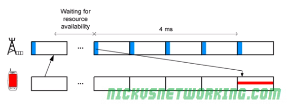
The UE must request the resources from the eNB and wait for them to be allocated in the next uplink resource block.
There is a 4ms delay between a resource block being allocated in an allocation table by the eNB for the uplink and it being used by the UE to send data. This gives the UE time to get the data ready to go into the resource block.
The UE requests a resource from the eNB (covered later) and the eNB publishes an allocation table in the next subframe, however this allocation table is to be used in 4 subframes time.
The UE then buffers this allocation table and uses it in 4 subframes time.
By having this delay in using the resource table / allocating resource tables in advance, it allows our UEs to prepare the message for transmission, encode it, modulate it, etc.
The image below shows the UE in red requesting a resource for uplink from the eNB, the eNB then publishes the allocation table for 4 subframes time, the UE waits for 4 subframes to pass and then the UE transmits using the resources allocated in the allocation table published 4ms prior.
For example in the image below the UE with the RTNI of 64, represented in light blue, has requested a resource to send data (uplink), the eNB publishes an uplink allocation table in the next subframe, and the UE has then 4 subframes to prepare the data for transmission before sending the data using the resources allocated in the allocation table sent to it 4 subframes prior.
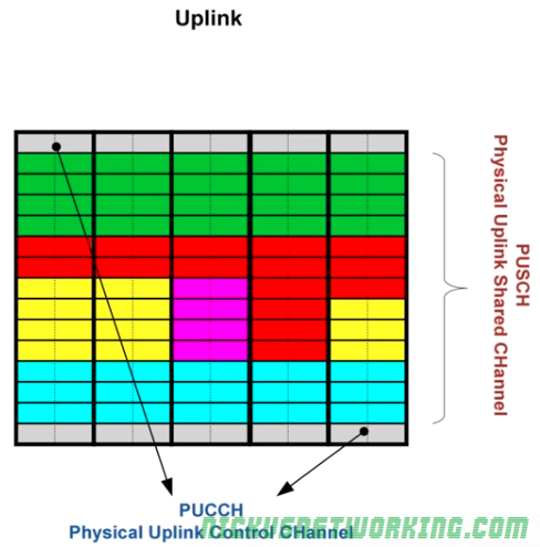
Like in the Downlink, Uplink transmissions are managed by a Control Channel and data is contained within a Data Channel.
The Physical Uplink Control Channel(PUCCH) contains the control information and the resource tables for the uplink (to be used in 4 subsframes time), shown in gray.
The data being sent from the UEs is contained in Physical Uplink Shared Channels (PUSCH) allocated 4ms prior in a PUCCH.
When a UE has data to transmit it transmits on the PUCCH to request a resource block for the uplink data.
As spectrum is sparse and expensive, so it must be used wisely and shared across multiple users.
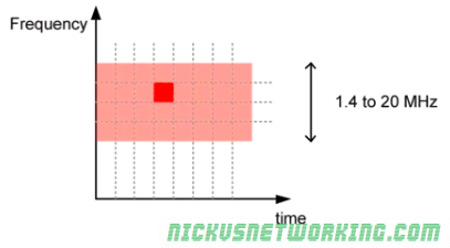
LTE shares spectrum in both frequency and time.
L
LTE can use bandwidths from 1.4Mhz to 20Mhz, based on the spectrum owned and needs of the area.
Spectrum is divided into sub-carriers, allowing each subcarrier to be allocated to a different user, and these subcarriers are re-allocated by the eNB based on the terminal’s needs.
Resource Element (RE)
A Resource Element is the time and frequency a single symbol can be transmitted on.
Resource Elements are allocated by the eNB to UEs and the UE transmits on it’s allocated resource element one symbol.
The size of the data in the symbol is defined by the MCS used.
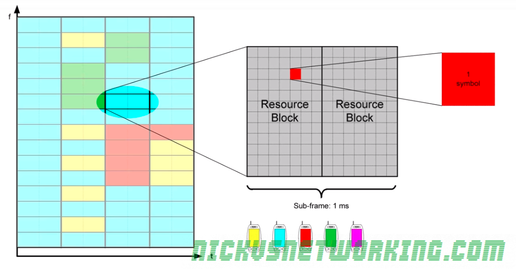
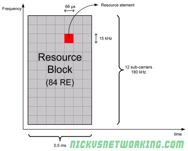
One Resource Element is contained within 1 subcarrier of 15kHz lasting 66μ s.
Resource Blocks (RB)
Because resource elements are so small, they’re managed in Resource Blocks.
Each Resource Block lasts 0.5ms with 12 sub carriers on each, allowing for 84 Resource Elements in per Resource Block.
The number of Resource Blocks that can be used is determined by the spectrum available.
As we can calculate a Resource Block occupies 180kHz of bandwidth, how many Resource Blocks we can have is determined by how many will fit into our bandwidth.
A system using the minimum bandwidth of 1.4Mhz will have 6 RBs available (1.4Mhz divides into 6 complete 180kHz RBs), while one using the maximum of 20Mhz will have 100 RBs available.
Not all the REs in an RB can be used by terminals though, many of them are reserved for LTE control channels.
The purple and red blocks are reserved as control channels
Meaning only the white REs shown above can be filled with user traffic.
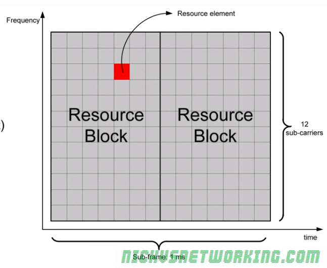
Sub-Frame
Every 1ms (or 2 Resource Blocks) LTE reallocates the RBs to the terminals that need to communicate.
This means Resource Blocks are allocated in pairs, called a subframe, lasting 1ms.
Subframe, RB, RE Hierarchy
Each subframe is 1ms long and made up of 2 0.5ms Resource Blocks.
Each Resource Block contains 84 Resource Elements, each of which contain one symbol of data.
Resource Allocation in Uplink
When a device needs to transmit data it is allocated one or more resource blocks.
If the number of resource blocks is not enough it can be allocated more in the next subframes.
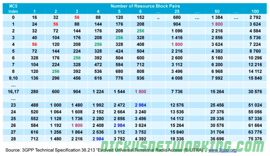
The amount of data a device can transmit in each subframe is called a Transport Block and is made up of the number of RBs and the modulation (MCS) used.
Table of MCS vs Resource Block Pairs (Subframes) and resulting data throughput rate in bits
The sub frame containing contain data for various terminals is shown below in different colors.
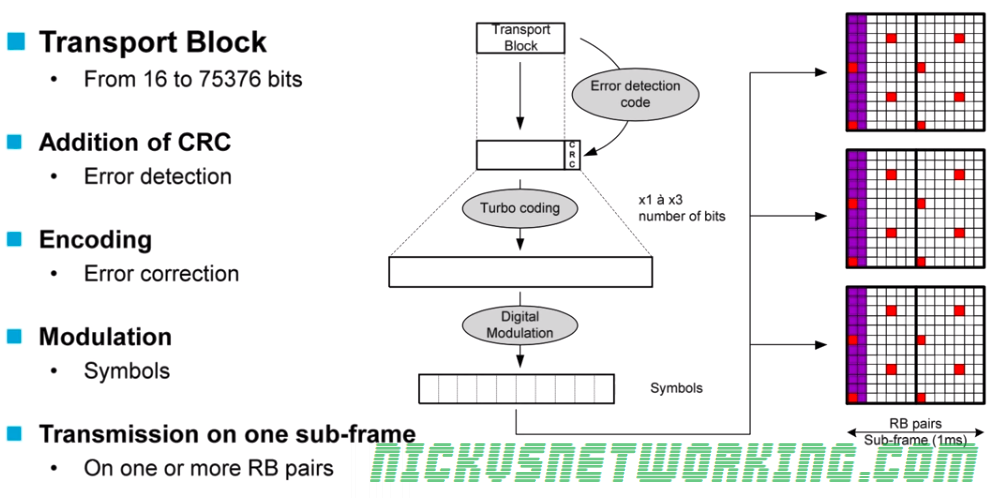
Transmission Chain
Transport Blocks are filled with data based on the Transport Block size.
CRC is added to detect errors.
Data is encoded to help recover data containing errors. (Defined by MCS)
Data is modulated (Using modulation scheme defined by MCS)
Data is transmitted in the user-data part that has been allocated in one or more Resource Block Pairs.