ARP in LTE is not the Ethernet standard for address resolution, but rather the Allocation and Retention Policy.
A scenario may arise where on a congested cell another bearer is requested to be setup.
The P-GW, S-GW or eNB have to make a decision to either drop an existing bearer, or to refuse the request to setup a new bearer.
The ARP value is used to determine the priority of the bearer to be established compared to others,
For example a call to an emergency services number on a congested cell should drop any other bearers so the call can be made, thus the request for bearer for the VoLTE call would have a higher ARP value than the other bearers and the P-GW, S-GW or eNB would drop an existing bearer with a lower ARP value to accommodate the new bearer with a higher ARP value.
ARP is only used when setting up a new bearer, not to determine how much priority is given to that bearer once it’s established (that’s defined by the QCI).
MBR stands for Maximum Bit Rate, and it defines the maximum rate traffic can flow between a UE and the network.
It can be defined on several levels:
MBR per Bearer
This is the maximum bit rate per bearer, this rate can be exceeded but if it is exceeded it’s QoS (QCI) values for the traffic peaking higher than the MBR is back to best-effort.
AMBR
Aggregate Maximum Bit Rate – Maximum bit rate of all Service Data Flows / Bearers to and from the network from a single UE.
APN-MBR
The APN-MBR allows the operator to set a maximum bit rate per APN, for example an operator may choose to limit the MBR for subscriber on an APN for a MVNO to give it’s direct customers a higher speed.
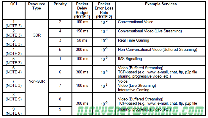
The QCI (Quality Class Indicator) is a value of 0-9 to denote the service type and the maximum delays, packet loss and throughput the service requires.
Different data flows have different service requirements, let’s look at some examples:
A VoLTE call requires low latency and low packet loss, without low latency it’ll be impossible to hold a conversation with long delays, and with high packet loss you won’t be able to hear each other.
On the other hand a HTTP (Web) browsing session will be impervious to high latency or packet loss – the only perceived change would be slightly longer page load times as lost packets are resent and added delay on load of a few hundred ms.
So now we understand the different requirements of data flows, let’s look at the columns in the table above so we can understand what they actually signify:
GBR
Guaranteed Bit Rate bearers means our eNB will reserve resource blocks to carry this data no matter what, it’ll have those resource blocks ready to transport this data.
Even if the data’s not flowing a GBR means the resources are reserved even if nothing is going through them.
This means those resource blocks can’t be shared by other users on the network. The Uu interface in the E-UTRAN is shared between UEs in time and frequency, but with GBR bearers parts of this can be reserved exclusively for use by that traffic.
Non-GBR
With a Non-GBR bearer this means there is no guaranteed bit rate, and it’s just best effort.
Non-GBR traffic is scheduled onto resource blocks when they’re not in use by other non-GBR traffic or by GBR traffic.
Priority
The priory value is used for preemption by the PCRF.
The lower the value the more quickly it’ll be processed and scheduled onto the Uu interface.
Packet Delay Budget
Maximum allowable packet delay as measured from P-GW to UE.
Most of the budget relates to the over-the-air scheduling delays.
The eNB uses the QCI information to make its scheduling decisions and packet prioritisation to ensure that the QoS requirements are met on a per-EPS-bearer basis.
(20ms is typically subtracted from this value to account for the radio propagation delay on the Uu interface)
Packet Error Loss Rate (PELR)
This is packets lost on the Uu interface, that have been sent but not confirmed received.
The PELR is an upper boundary for how high this can go, based on the SDUs (IP Packets) that have been processed by the sender on RLC but not delivered up to the next layers (PDCP) by the receiver.
(Any traffic bursting above the GBR is not counted toward the PELR)
GBR is a confusing concept at the start when looking at LTE but it’s actually kind of simple when we break it down.
GBR stands for Guaranteed Bit Rate, meaning the UE is guaranteed a set bit rate for the bearer.
The default bearer is always a non-GBR bearer, with best effort data rates.
Let’s look at non-GBR bearers to understand the need for GBR bearers:
As the Uu (Air) interface is shared between many UEs, each is able to transfer data. Let’s take an example of a cell with two UEs in it and not much bandwidth available.
If UE1 and UE2 are both sending the same amount of data it’ll be evenly split between the two.
But if UE1 starts sending a huge amount of data (high bit rate) this will impact on the other UEs in the cells ability to send data over the air as it’s a shared resource.
So if UE2 needs to send a stream of small but important data over the air interface, while UE2 is sending huge amounts of data, we’d have a problem.
To address this we introduce the concept of a Guaranteed Bit Rate. We tell the eNB that the bearer carrying UE2’s small but important data needs a Guaranteed Bit Rate and it reserves blocks on the air interface for UE2’s data.
So now we’ve seen the need for GBR there’s the counter point – the cost.
While UE1 can still continue sending but the eNB will schedule fewer resource blocks to it as it’s reserved some for UE2’s data flow.
If we introduced more and more UEs each requiring GBR bearers, eventually our non-GBR traffic would simply not get through, so GBR bearers have to be used sparingly.
Note: IP data isn’t like frame relay or circuit switched data that’s consistent, bit rate can spike and drop away all the time. GBR guarantees a minimum bit rate, which is generally tuned to the requirements of the data flow. For example a GBR for a Voice over IP call would reserve enough for the media (RTP stream) but no more, so as not to use up resources it doesn’t need.
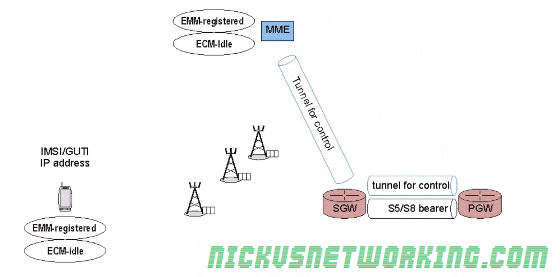
As we just saw when a terminal moves to ECC-Idle while in EMM-Registered state, it releases it’s radio resources, so what happens when the UE needs to send / receive data again?
UE is disconnected from Radio Resources (ECM-Idle & EMM Registered)
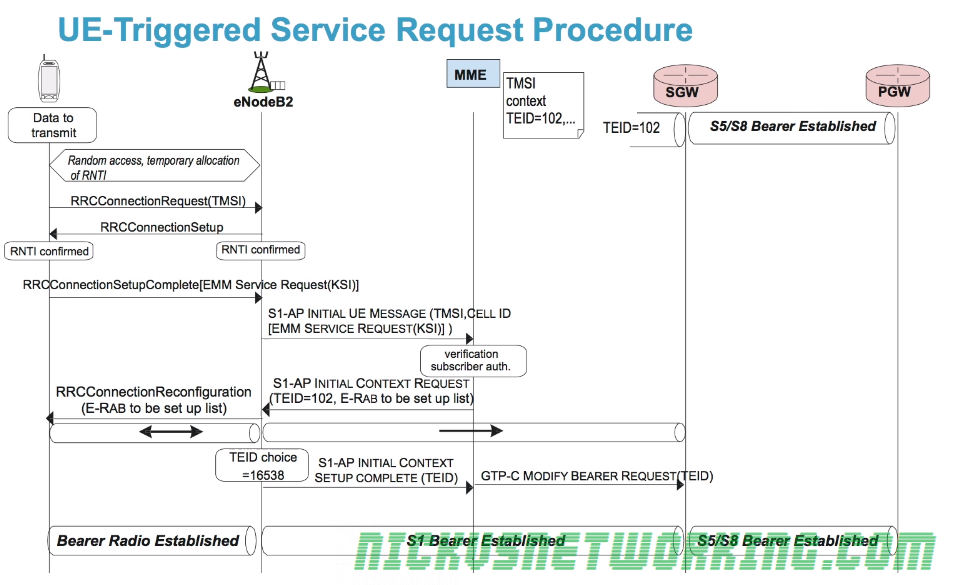
While one option could have been to go through the full attach procedure again when the UE is triggered, the 3GPP team wanted the re-connection process to be as fast as possible.
As we saw in the last post we don’t drop the S-GW <-> P-GW tunnel, which saves time on re-establishing a connection. The S1 tunnel is also not completely released; the TEID value from the S-GW end of the tunnel is saved by the MME so it can be reused by the new tunnel when the UE reconnects, without needing to inform the S-GW.
One of the common themes we cover over and over in the 4G discussion is the desire to preserve energy on the UE RF side of things, to extend battery life as much as possible.
The 3GPPs requirements for LTE also included the smallest round trip times, defining less than 5 ms in unload condition, so traffic to the UE must be routed as quickly as possible.
Mobiles are by their very nature, mobile.
This requires UEs to constantly monitor the RF conditions and the signal measurements from different base stations so the UE can determine if it’s time to handoff to another cell due to going further from one eNB and closer to another, or another eNB offering better RF conditions (Strong signal etc).
This requires regular exchanges of messages and checks, but this would take a lot of energy and eat up battery usage.
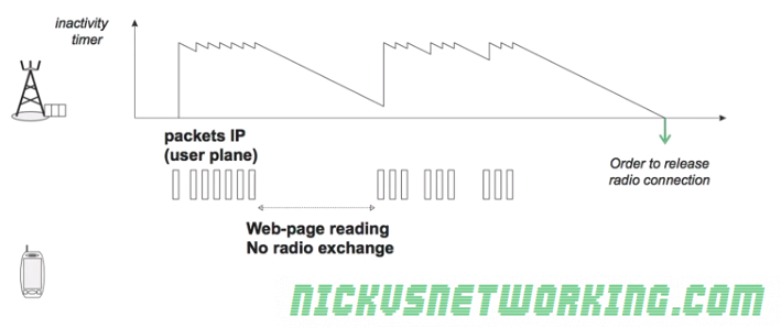
Instead we avoid maintaining the radio connection all the time with the aid of an inactivity timer on the eNB.
For as long as user data is flowing over the air interface the connection is maintained, for example web browsing, the inactivity timer is constantly reset as traffic flows.
However when the eNB detects no packets sent or received by the UE the timer starts counting down from it’s set value.
When the inactivity timer reaches 0 the RRC Connection is released and the UE no longer has an RNTI.
The UE is still listening to an eNB, it’s just not sending data to it it and visa-versa.
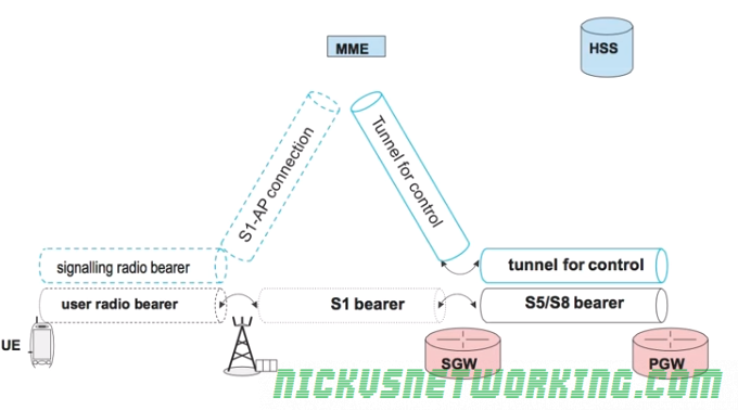
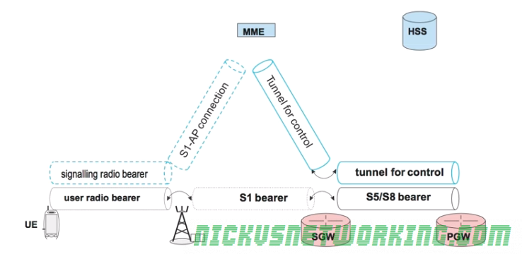
As the radio bearer has been removed the UE the S1-AP and S1-UP bearers between the eNB and the MME and the eNB and the S-GW respectively, can be torn down.
This means the MME is no long sure of exactly which eNB the UE is listening on.
This is referred to as ECM_IDLE state as there is no radio connection, and the network is unaware of the precise location of the UE.
An ECM_ACTIVE state is the state when the UE is connected to an eNB with an RNTI and it’s inactivity timer has not reached 0.
The dotted line bearers shown in the image above frequently change between active and inactive based on the ECM_ACTIVE / ECM_INACTIVE state of the bearers.
EPS Mobility Management (EMM) has two states – EMM-Registered (UE reachable) and EMM-Deregistered (UE not reachable).
A UE is in the deregistered state when it is not rechable, for example not currently powered up or in flight mode.
The MME memorizes the state of each UE and it’s context elements such as it’s most recent GUTI, IMSI, security parameters etc.
Attach Procedure
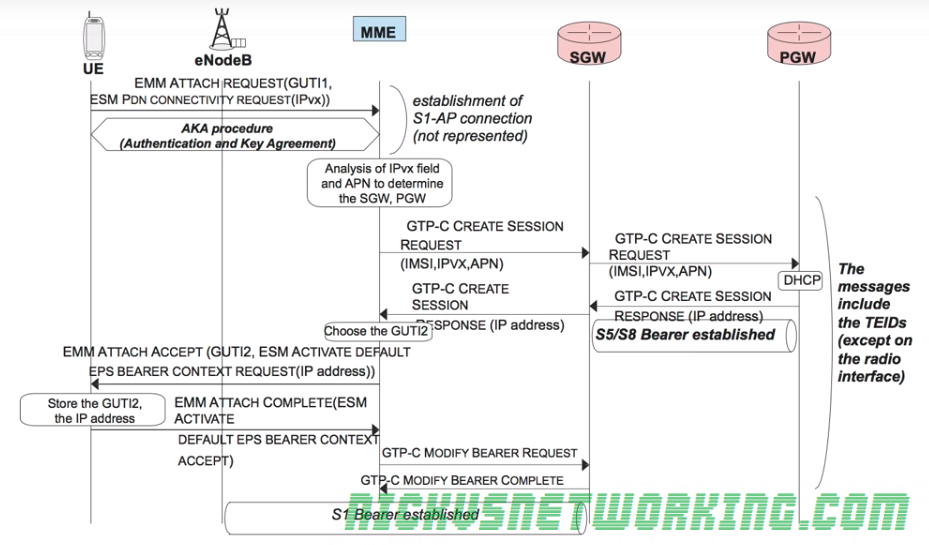
To attach to the network a UE sends an EMM Attach Request with it’s most recent GUTI to the MME.
In the same request the UE also includes an ESM PDN Connectivity Request to gain access to the external networks.
The Authentication & Key Agreement procedure is followed between the UE and the MME/HSS to authenticate the network and the subscriber.
One this is done the MME looks at the connectivity requested and the APN of the subscriber, the MME then selects a Serving-Gateway and Packet-Gateway based on the APN.
The MME then sends a GTP-C Create Session Request along with the connectivity requested (IPv4/6), APN and IMSI of the subscriber and it’s allocated TEID for this tunnel to the S-GW.
The S-GW also sends a GTP-C Create Session Request along with the connectivity requested (IPv4/6), APN and IMSI of the subscriber to the P-GW, along with the S-GW’s allocated TEID for this tunnel too.
The P-GW then sends a GTP-C Create Session back to the S-GW containing it’s TEID and it also includes the IP Address to be allocated to the UE.
A GTP session is now setup between the P-GW and the S-GW for this bearer, with the TEID values added to the TEID management tables on both devices. This GTP tunnel is referred to an S5 (home) or an S8 (roaming) Bearer in 3GPP parlance.
Another GTP-C Create Session message with it’s own TEID is also sent from the S-GW to the MME.
The MME, S-GW and P-GW now each know TEID for each of the 2 tunnels setup (MME<->S-GW, S-GW<->P-GW) so have what they need to fill their TEID management tables.
When the MME recieves the GTP-C Create Session with the IP Address for the UE it sends an EMM Attach Accept and a EPS Bearer Context Setup Request containing the IP Address the P-GW allocated to the UE to the UE itself.
The UE stores the allocated IP and sends an acknowledgement to the MME in the form of an EMM Attach Complete message back to the MME.
The MME sends a GTP-C Modify Bearer Request which transfers the bearer setup between MME and SGW and modifies it to be between the SGW and the eNB.
The S-GW sends back a GTP-C Modify Bearer Complete message and modifies the GTP tunnel to be between the SGW and the eNB. A S1 bearer is now established for carrying user data from the eNB to the SGW.
Once this procedure is complete the UE is now in the EMM Registered State meaning it is known to the MME, it has a security association and has an IP Address.
The S-GW and the P-GW also stores the TEIDs for the UE.
Detach Procedure
When a UE detaches from the network (for example it powers down), the network must release all the tunnels for that UE, the MME state must be updated to EMM Deregistered and the MME must also keep a record for the last GUTI and security keys,
To detach from the network the UE sends a RLC UL Information Transfer message containing an EMM Detach Request which includes it’s current GUTI.
As soon as the UE recivers confirmation from the eNB the UE can power down, but the eNB must inform the network of the disconnection so the resources can be released.
The eNB sends a S1Ap Uplink NAS Transport message containing a EMM Detach Request with the UE’s GUTI to the MME.
The MME can then release the security context,
The MME then sends a GTP-C Delete Session Request to the S-GW.
Upon recipt of this request the S-GW requests the P-GW tears down it’s tunnel between the P-GW and S-GW (aka the S5/S8 Bearer) by sending it’s own GTP-C Delete Session Request to the P-GW.
Once the S-GW has confirmation the tunnel has been taken down (In the form of a GTP-C Delete Session Response) the S-GW sends a GTP-C Delete Session Response to the MME.
The MME must signal to the eNB it can release the RNTI and the radio resources. To do this it sends a S1-AP UE Context Release Command which releases the radio bearers and tears down the S1-UP bearer between the eNB and the S-GW.
The eNB then sends a S1-AP UE Context Release Completeto the MME.
Finally the MME sends a Diameter Notification Request (PGW and APN Removed) to the HSS to update the HSS of the user’s status, the HSS signals back with a Diameter Notification Answer and the HSS knows the user is no longer reachable.