Tag Archives: eNodeB

Enable GPS/GLONASS Sync on Huawei BTS3900

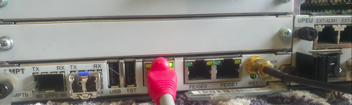
Our BTS is going to need an accurate clock source in order to run, so without access to crazy accurate Timing over Packet systems or TDM links to use as reference sources, I’ve opted to use the GPS/GLONASS receiver built into the LMPT card.

Add new GPS with ID 0 on LMPT in slot 7 of cabinet 1:

ADD GPS: GN=0, CN=1, SRN=7, CABLE_LEN=3, MODE=GPS/GLONASS;

Check GPS has sync (May take some time) using the Display GPS command;

DSP GPS: GN=0;

Assuming you’ve got an antenna connected and can see the sky, after ~10 minutes running the DSP GPS:; command again should show you an output like this:

+++    4-PAL0089624        2020-11-28 01:06:55
O&M    #806355684
%%DSP GPS: GN=0;%%
RETCODE = 0  Operation succeeded.

Display GPS State
-----------------
                 GPS Clock No.  =  0
                GPS Card State  =  Normal
                 GPS Card Type  =  M12M
                 GPS Work Mode  =  GPS
                   Hold Status  =  UNHOLDED
         GPS Satellites Traced  =  4
     GLONASS Satellites Traced  =  0
         BDS Satellites Traced  =  0
Antenna Longitude(1e-6 degree)  =  144599999
 Antenna Latitude(1e-6 degree)  =  -37000000
           Antenna Altitude(m)  =  613
         Antenna Angle(degree)  =  5
             Link Active State  =  Activated
              Feeder Delay(ns)  =  15
                   GPS Version  =  NULL
(Number of results = 1)


---    END

Showing the GPS has got sync and a location fix,

Next we set BTS to use GPS as time source,

SET TIMESRC: TIMESRC=GPS;

Finally we’ll verify the Time is in sync on the BTS using the list time command:

DSP TIME:;
+++    4-PAL0089624        2020-11-28 01:09:22
O&M    #806355690
%%DSP TIME:;%%
RETCODE = 0  Operation succeeded.

Time Information
----------------
Time  =  2020-11-28 01:09:22 GMT+00:00

---    END

Optionally you may wish to add a timezone, using the SET TZ:; command, but I’ve opted to keep it in UTC for simplicity.

Huawei BTS 3900 LMPT Basic Config

This post is one in a series documenting my adventures attempting to configure a used BTS 3900 to function as a eNB in my lab.

There are 5 network ports on the LMPT card:

  • 2x SFP cages – SFP 0 and SFP 1
  • 1x 10/100 Ethernet port – ETH – Used to access the Local Maintenance terminal
  • 2x Fe/Ge ports – Fe/Ge0 and Fe/Ge1

Configuring the Ethernet Ports

What took me a little while to realise is that SFP0 and Fe/Ge0 are paired, they’re really only one interface. This means you can only use one at a time – you can’t use SFP0 and Fe/Ge0 simultaneously- Same with SFP1 and Fe/Ge1.

Before we get started we’ll list the current interfaces:

DSP ETHPORT:;

Assuming the interfaces aren’t there, we’ll need to add the interfaces, in my case the LMPT card is in Chassis 1, Slot number 7.

ADD ETHPORT: SRN=1, SN=7, SBT=BASE_BOARD, PN=0, PA=AUTO, SPEED=AUTO, DUPLEX=AUTO, USERLABEL="SFP_Fe_Ge_0";
ADD ETHPORT: SRN=1, SN=7, SBT=BASE_BOARD, PN=1, PA=AUTO, SPEED=AUTO, DUPLEX=AUTO, USERLABEL="SFP_Fe_Ge_1";

And then we’ve got to add an IP to one of the interfaces, in the below example I’ve added 10.0.1.210/24 to port 0 (which can be either SFP0 or Fe/Ge0).

ADD DEVIP: SRN=1, SN=7, SBT=BASE_BOARD, PT=ETH, PN=0, IP="10.0.1.210", MASK="255.255.255.0", USERLABEL="SFP_Fe/Ge_0"; 

At this point I plugged into the Fe/Ge0 port into my switch, and from my laptop on the same 10.0.1.0/24 subnet, I was able to ping the eNodeB.

And now we can check the status of the port:

DSP ETHPORT: SRN=1, SN=7, SBT=BASE_BOARD, PN=0;
+++    4-PAL0089624        2020-11-28 00:19:13
O&M    #806355532
%%DSP ETHPORT: SRN=1, SN=7, SBT=BASE_BOARD;%%
RETCODE = 0  Operation succeeded.

DSP ETHPORT Result
------------------
                           Cabinet No.  =  0
                           Subrack No.  =  1
                              Slot No.  =  7
                         Subboard Type  =  Base Board
                              Port No.  =  0
                        Port Attribute  =  Copper
                           Port Status  =  Up
                 Physical Layer Status  =  Up
       Maximum Transmission Unit(byte)  =  1500
                             ARP Proxy  =  Enable
                          Flow Control  =  Open
                           MAC Address  =  DCD2-07FC-A9E8
                       Loopback Status  =  No Loop
               In Loopback Mode or Not  =  No
                 Ethernet OAM 3AH Flag  =  Disable
          Number of RX Packets(packet)  =  1682
              Number of RX Bytes(byte)  =  163929
Number of RX CRC Error Packets(packet)  =  2
                    RX Traffic(byte/s)  =  259
          Number of TX Packets(packet)  =  53
              Number of TX Bytes(byte)  =  13952
                    TX Traffic(byte/s)  =  0
  Local Configuration Negotiation Mode  =  Automatic Negotiation
         Local Actual Negotiation Mode  =  Automatic Negotiation
                           Local Speed  =  100M
                          Local Duplex  =  Full Duplex
          Peer Actual Negotiation Mode  =  Automatic Negotiation
                            Peer Speed  =  100M
                           Peer Duplex  =  Full Duplex
                         Number of IPs  =  1
                       IP Address List  =  10.0.1.210 255.255.255.0
(Number of results = 1)


---    END

On with the rest of the config,

Adding a default route:

ADD IPRT: RTIDX=0, SRN=1, SN=7, SBT=BASE_BOARD, DSTIP="0.0.0.0", DSTMASK="0.0.0.0", RTTYPE=NEXTHOP, NEXTHOP="10.0.1.1", MTUSWITCH=OFF, DESCRI="Default Route";

Setting a DNS Server:

ADD DNSSRV: DNSSRVID=0, IPVER=IPv4, DNSCIP4="10.0.1.210", DNSSIP4="1.1.1.1";

Ensure you can ping the DNS server & in my case the MME:

PING: SRN=1, SN=7, SRCIP="10.0.1.210", DSTIP="1.1.1.1", CONTPING=DISABLE, APPTIF=NO;
PING: SRN=1, SN=7, SRCIP="10.0.1.210", DSTIP="10.0.1.183", CONTPING=DISABLE, APPTIF=NO;

And with that, you’ve got the network side of the config done on the eNodeB.

At this stage you’re able to unplug from the ETH port you’ve got the WebLMT connection to, and just connect to it like any other network device.

There’s a few more steps before we bring cells on the air, we’ve got to set timing sources, configure a connection to an MME and S-GW, configure the Carrier settings and add the radios and sectors, but this will get you to the stage where you no longer need to plug directly into the eNB to configure it.

Connecting to a Huawei BTS3900

Meta: This post is a series chronicling my adventures with a second hand Huawei BTS3900 I purchased. You can find an index of these posts here.

So you purchased a used Macro base station online, good for you.

Now you need to know how to configure it.

First things first, you’ll need to connect to the MPT card – Main Processing & Transmission,

Chances are you’ll have a LMPT (LTE Main Processing & Transmission) or UMPT (Universal Main Processing & Transmission) card.

Set your Ethernet adaptor’s IP to 192.168.0.50/24,

If you’ve got a LMPT card you plug into the ETH port, and then browse to 192.168.0.49, to hit the WebLMT interface.

If you’ve got a UMPT card, you’d need to connect a USB-NIC to the USB port.

And presto, we can reach the WebLMT interface;

I’ve found Firefox on Linux works OK – some functions don’t work, but a VM running IE and Java 7 does the trick just fine.

Huawei BBU (Baseband Unit) for LTE/UMTS/GSM also known as the BTS 3900 / BBU 3900

My used Huawei BTS3900 LTE RAN Adventure – The Impulse Purchase

Meta: The Australian government made up it’s mind some time ago that Huawei would be blacklisted from providing equipment for 5G networks.
Several other countries have adopted the same policy in regards, and as such, deployed Huawei tech is being replaced, and some of it filters down to online auction sites…

So I kind of purchased an item described as “Huawei BBU3900” with a handful of unknown cards and 2 LRFU units, for just over $100.

My current lab setup is a single commercial picocell and a draw of SDR hardware that works with mixed results, so the idea of having a commercial macro cell to play with seemed like a great idea, I put lowball offer in and the seller accepted.

Now would be a good time to point out I don’t know much about RAN and it’s been a long time since I’ve been working on power systems, so this is shaping up to be a fun project.

I did a Huawei RAN course years ago and remembered the rough ingredients required for LTE:

  1. You needed either RRUs (Remote Radio Units) or RFUs (Radio Frequency Units) to handle the RF side of things.
    RRUs are designed for outdoor use (such as mounting on the tower) and RFUs are designed for indoor use, like mounting in a cabinet.
    I’ve ended up with two LRFUe units, which I can join together for 2x MIMO, operate on Band 28 and can put out a whopping 80W of transmit power, yes I’m going to need some big attenuators…
  2. You need a Baseband Processor card to tell the Radio units what do do.
    The card connects the CPRIs (Typically optic fiber links) between the radio units and the baseband.
    The chassis I purchased came with a stack of WBBP (For WCDMA) cards and a single LBBP card for LTE. The LBBP card has 6 SFP ports for the CPRI interfaces, which is more than enough for my little lab. (You can also daisy-chain CPRIs so I’m not even limited to 6 Radio Units.)
  3. You need a backplane and a place for the cards to live – this is the BBU3900 chassis. It’s got basic switching to allow communication between cards, a chassis to distribute power and cooling.
    (Unlike the Ericson units there is actually a backplane for communications in the Huawei chassis – the Ericsson RBS series has is just power and cooling in the chassis)
  4. Optional – Dedicated transmission card, I’ve ended up with a Universal Transmission Processor (UTRP9) with 2x Gig Ethernet and 2x Fast Ethernet ports for transmission. This will only work for GSM and UMTS though, not LTE, so not much use for me.
  5. You need something to handle main processing (LTE / Universal Main Processing and Transmission Unit (LMPT / UMPT)).
    Unfortunately the unit I’ve ended up with only came with a WMPT (For WCDMA), so back online to find either an LMPT (LTE) or UMPT (Universal (2G/3G/4G))…
  6. You need a Universal Power and Environment Module (UPEU) to power up the chassis and handle external IO for things like temperature alarms, door sensors and fire detectors. This chassis has two for redundancy / extra IO & extra power capacity.

So in order to get this running I still need quite a few components:

  • Attenuators – I’ll be able to turn the power down, sure, but not to the levels required to be legal.
  • Antennas – These are FDD units, so I’ll need two antennas for each RFU, on Band 28
  • Feeder Cables – To connect the antennas
  • SMF cables and SFPs – I’ve got a pile in my toolbox, but I’ll need to work out what’s supported by these units
  • A big -48vDC rectifier (I got the BBU3900 unit powered up with an existing supply I had, but I’m going to need something bigger for the power hungry RFUs)
  • DC Distribution Unit – Something to split the DC between the RFUs and the BBU, and protect against overload / short
  • USB-Network adapter – For OAM access to the unit – Found these cheaply online and got one on the way
  • The LTE Main Processing & Transmission (LMPT) card – Ordered a second hand one from another seller

I powered up the BTA3900 and sniffed the traffic, and can see it trying to reach an RNC.

Unfortunately with no open source RNC options I won’t be posting much on the topic of UMTS or getting the UMTS/WCDMA side of things on the air anytime soon…

So that’s the start of the adventure.

I don’t know if I’ll get this all working, but I’m learning a lot in the process, and that’s all that really matters…

Note: I think this is the course I did from Huawei on the BBU3900…