I talked a bit in my last post about using osmo-sim-auth to authenticate against a USIM / SIM card when it’s not in a phone,
I thought I’d expand a little on how the Crypto side of things works in LTE & NR (also known as 4G & 5G).
Authentication primarily happens in two places, one at each end of the network, the Home Subscriber Server and in the USIM card. Let’s take a look at each of them.
On the USIM
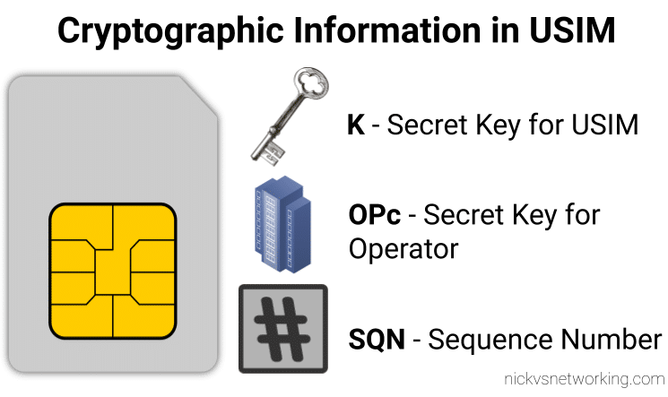
On the USIM we’ve got two values that are entered in when the USIM is provisioned, the K key – Our secret key, and an OPc key (operator key).
These two keys are the basis of all the cryptography that goes on, so should never be divulged.
The only other place to have these two keys in the HSS, which associates each K key and OPc key combination with an IMSI.
The USIM also stores the SQN a sequence number, this is used to prevent replay attacks and is incremented after each authentication challenge, starting at 1 for the first authentication challenge and counting up from there.
On the HSS
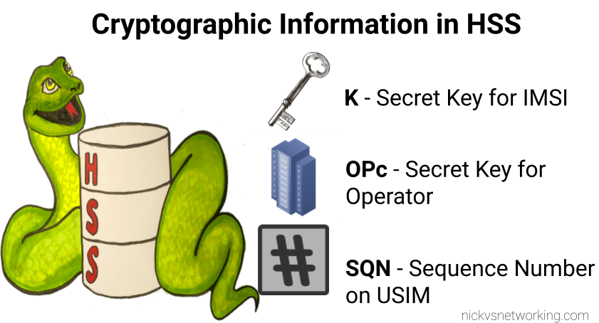
On the HSS we have the K key (Secret key), OPc key (Operator key) and SQN (Sequence Number) for each IMSI on our network.
Each time a IMSI authenticates itself we increment the SQN, so the value of the SQN on the HSS and on the USIM should (almost) always match.
Authentication Options
Let’s imagine we’re designing the authentication between the USIM and the Network; let’s look at some options for how we can authenticate everyone and why we use the process we use.
Failed Option 1 – Passwords in the Clear
The HSS could ask the USIM to send it’s K and OPc values, compare them to what the HSS has in place and then either accept or reject the USIM depending on if they match.
The obvious problem with this that to send this information we broadcast our supposedly secret K and OPc keys over the air, so anyone listening would get our secret values, and they’re not so secret anymore.
This is why we don’t use this method.
Failed Option 2 – Basic Crypto
So we’ve seen that sending our keys publicly, is out of the question.
The HSS could ask the USIM to mix it’s K key and OPc key in such a way that only someone with both keys could unmix them.
This is done with some cryptographic black magic, all you need to know is it’s a one way function you enter in values and you get the same result every time with the same input, but you can’t work out the input from the result.
The HSS could then get the USIM to send back the result of mixing up both keys, mix the two keys it knows and compare them.
The HSS mixes the two keys itself, and get’s it’s own result called XRES (Expected Result). If the RES (result) of mixing up the keys by the USIM is matches the result when the HSS mixes the keys in the same way (XRES (Expected Result)), the user is authenticated.
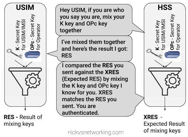
The result of mixing the keys by the USIM is called RES (Result), while the result of the HSS mixing the keys is called XRES (Expected Result).
This is a better solution but has some limitations, because our special mixing of keys gets the same RES each time we put in our OPc and K keys each time a subscriber authenticates to the network the RES (result) of mixing the keys is going to be the same.
This is vulnerable to replay attacks. An attacker don’t need to know the two secret keys (K & OPc) that went into creating the RES (resulting output) , the attacker would just need to know the result of RES, which is sent over the air for anyone to hear.
This is why we don’t use this method.
If the attacker sends the same RES they could still authenticate.
Failed Option 3 – Mix keys & add Random
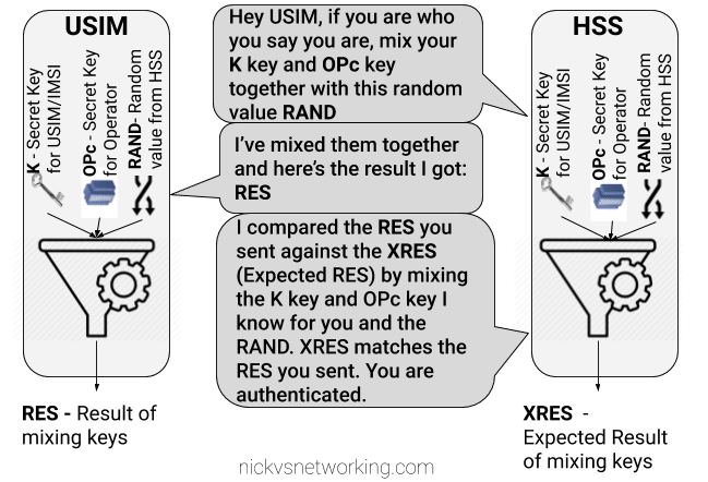
To prevent these replay attacks we add an element of randomness, so the HSS generates a random string of garbage called RAND, and sends it to the USIM.
The USIM then mixes RAND (the random string) the K key and OPc key and sends back the RES (Result).
Because we introduced a RAND value, every time the RAND is different the RES is different. This prevents against the replay attacks we were vulnerable to in our last example.
If the result the USIM calculated with the K key, OPc key and random data is the same as the USIM calculated with the same K key, OPc key and same random data, the user is authenticated.
While an attacker could reply with the same RES, the random data (RAND) will change each time the user authenticates, meaning that response will be invalid.
While an attacker could reply with the same RES, the random data (RAND) will change each time the user authenticates, meaning that response will be invalid.
The problem here is now the network has authenticated the USIM, the USIM hasn’t actually verified it’s talking to the real network.
This is why we don’t use this method.
GSM authentication worked like this, but in a GSM network you could setup your HLR (The GSM version of a HSS) to allow in every subscriber regardless of what the value of RES they sent back was, meaning it didn’t look at the keys at all, this meant attackers could setup fake base stations to capture users.
Option 4 – Mutual Authentication (Real World*)
So from the previous options we’ve learned:
- Our network needs to authenticate our subscribers, in a way that can’t be spoofed / replayed so we know who to bill & where to route traffic.
- Our subscribers need to authenticate the network so they know they can trust it to carry their traffic.
So our USIM needs to authenticate the network, in the same way the network authenticates the USIM.
To do this we introduce a new key for network authentication, called AUTN.
The AUTN key is generated by the HSS by mixing the secret keys and RAND values together, but in a different way to how we mix the keys to get RES. (Otherwise we’d get the same key).
This AUTN key is sent to the USIM along with the RAND value. The USIM runs the same mixing on it’s private keys and RAND the HSS did to generate the AUTN , except this is the USIM generated – An Expected AUTN key (XAUTN). The USIM compares XAUTN and AUTN to make sure they match. If they do, the USIM then knows the network knows their secret keys.
The USIM then does the same mixing it did in the previous option to generate the RES key and send it back.

The network has now authenticated the subscriber (HSS has authenticated the USIM via RES key) and the subscriber has authenticated the USIM (USIM authenticates HSS via AUTN key).
*This is a slightly simplified version of how EUTRAN / LTE authentication works between the HSS and the USIM – In reality there are a few extra values, such as SQN to take into consideration and the USIM talks to to the MME not the HSS directly.
I’ll do a follow up post covering the more nitty-gritty elements, AMF and SQN fields, OP vs OPc keys, SQN Resync, how this information is transfered in the Authentication Information Answer and how KASME keys are used / distributed.