So far in our lab we’ve got connectivity between to points, but we’re not carrying any useful data on top of it.
In the same way that TCP is great, but what makes it really useful is carrying application layers like HTTP on top, MTP3 exists to facilitate carrying higher-layer protocols, like ISUP, MAP, SCCP, etc, so let’s get some traffic onto our network.
ISUP is the ISDN User Part, ISUP is used to setup and teardown calls between two exchanges / SSPs – it’s the oldest and the most simple SS7 application to show off, so that’s what we’ll be working with today.
If you’ve not dealt much with ISDN in the past, then that’s OK – we’re not going to deep dive into all the nitty gritty of how ISDN Signaling works, but we’ll just skim the surface to showing how SS7/Sigtran transports the ISUPpackets. So you can see how SS7 is used to transport this protocol.
You can think of it a lot like SIP, which is if not the child of ISUP, then it at least bares a striking resemblance.
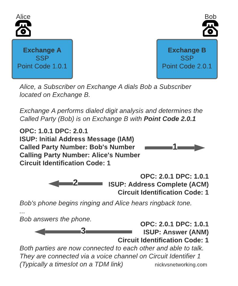
So let’s look at an ISUP call flow:
The call is initiated with an Initial Address Message (IAM), akin to a SIP INVITE, sent by the SSP/Exchange of the calling party to the SSP/Exchange of the called party. When the remote party starts to ring, the remote exchange sends an Address Complete (ACM), which is similar to a 100 TRYING in SIP. Once the remote party answers, the remote exchange sends back an Answer Message (ANM), and our call starts, just like a 200 OK.
Rather than SDP for transferring media, timeslots or predefined channels / circuits are defined, each identified by a number, which both sides will use for the media path.
Finally whichever side terminates the call will send a Release (REL) message, which is confirmed with the Release Complete (RLC).
I told you we’d be quick!
So that’s the basics of ISUP, in our next post we’ll do some PCAP analysis on real world ISUP flows!
This is part of a series of posts looking into SS7 and Sigtran networks. We cover some basic theory and then get into the weeds with GNS3 based labs where we will build real SS7/Sigtran based networks and use them to carry traffic.
So, all going well at this point in the tutorial you’ve got your lab setup with SS7 links between our simulated countries, but we haven’t dug too deep into what’s going on.
Most of the juicy stuff happens in the higher layers, but in this post we’ll look at the Data-Link layer for SS7.
In TDM based SS7 networks, Data Link layer is handled by a layer called “MTP2” – Message Transfer Part 2, which is responsible for flow control and ensuring guaranteed delivery between two points on the network.
MTP2 provides the services you’d typically expect at the Data Link Layer; link alignment, CRC generation/verification, end to end transmission between two points, flow control and sequence verification, etc.
MTP2 is responsible for making the connection between two points capable of carrying those far more interesting upper layers, but it’s really important, particularly when we talk about SIGTRAN/SS7 over IP, to understand how this can be done, so you can understand how the networks fit together.
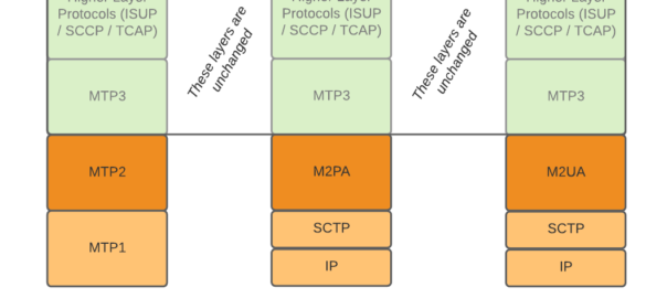
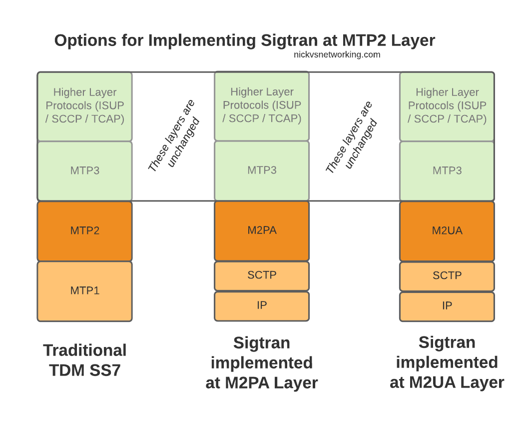
When we move from TDM based SS7 networks to IP based (Sigtran), MTP2 is removed, and can be replaced with one of two options for transporting Layer 2 messaging over IP, M2UA or M2PA.
All the layers above MTP2 on SS7 or M2UA/M2PA on Sigtran, are unchanged, and the upper layers have no visability that underneath, MTP2 has been replaced with M2UA or M2PA.
Taking MTP2 and putting it onto an IP based Layer 2 protocol is only one option for implementing Sigtran, there are others that we’ll look into as we go along, but with this variant the upper layers above Layer 2 (MTP3) remain changed.
Putting SS7 Data Link Layer (MTP2) onto IP
So the two options – M2UA and M2PA. Why do we have two options?
SS7 networks can be really complicated, and different operators may have different needs when converting these networks to IP.
To satisfy those requirements, there’s a bunch of different flavors of SS7 over IP (Sigtran) available to implement, so operators can select the one that meets their needs and use cases.
This means when we’re learning it, there’s a stack of different options to cover.
On the Layer 2 Level, let’s look at the two options we have in some more detail.
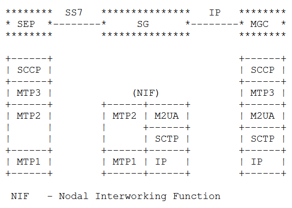
The M2UA Flavour
Image from RFC 4165 / 1.9. Differences Between M2PA and M2UA – Showing M2UA
With a “Nodal Interworking Function” using M2UA, the point codes between our two SS7 nodes remain unchanged.
The SS7 node on the left still talks MTP3 directly with the SS7 node on the right, and the NIF just transparently translates MTP2 into M2UA.
The best analogy I can come up with is that you can think of this as kind of like a Media Converter you’d use for converting between Cat5 to fibre – The devices at each end don’t know they’re not talking over a straight ethernet cable between them, but the media converter changes the transmission medium in between the two in a transparent manner.
M2UA acts in much the same way, except we’re transparently converting the layer 1 & layer 2 signaling, in a way that end devices in the network don’t need to be aware of.
The advantage of this option is that no config changes are needed, we’ve taken our Linksets that were running on TDM and converted them to IP so both ends of the linkset can be moved anywhere with IP connectivity, but transparently to the end devices.
For some carriers this is a real advantage – If you’ve got a dusty SSP running parts of your Customer Access Network, but the engineers who set it up retired long ago and you just want to drop those leased lines, M2UA could be a good option for you.
The disadvantage, as you might have guessed, is that we don’t get much value from just replacing the link from one point to another. It solves one problem, but doesn’t take that much of a step towards converging our network to run over IP.
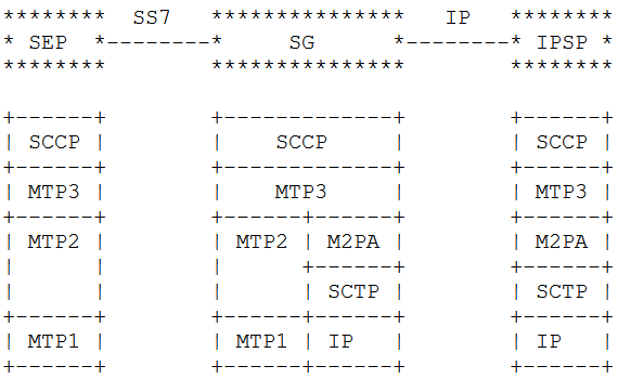
The M2PA Way
The M2PA way looks a bit different. You’ll notice we’ve got MTP3 on the Signaling Gateway we’re introducing into the network.
This means we need to add a point code between the SS7 node on the left and the SS7 node on the right, where there wasn’t one before, and we will need to update the routing tables on both to know to now route to each other via the point code of our Signaling Gateway rather than directly as the would have before we introduced the Signaling Gateway.
Image from RFC 4165 / 1.9. Differences Between M2PA and M2UA – Showing M2PA
We add another point code and an “active” SS7 device, but now we’ve got a lot more flexibility with what we can do, this no longer needs to be a point-to-point link, but with the introduction of the Signaling Gateway can be point-to-multipoint.
So which to chose? Well the answer is (as always) it depends.
If you cannot change any config on the end device (as the person who understood how all this stuff works retired long ago), then M2UA is the answer. M2UA is just an extension/branch of the MTP2 layer onto IP, it has no understanding / support for the higher-layers of SS7. M2UA is simpler, it doesn’t require as much understanding, it’s a quick-and-easy “drop-in” replacement for back-hauling SS7 onto IP. As it’s fairly dumb, M2UA can also allow us to split the load on a high traffic device across two or more SS7 nodes behind it, somewhat like a layer 2 load balancer, but this use case is pretty irrelevant these days.
M2PA on the other hand introduces a new Point Code (Operating on Layer 3 / MTP3) in between the two devices. This means we introduce a new point code in the path, so have to reconfigure the end devices, but affords us access to a lot of newer features. We can do all sorts of fancy things like routing of MTP3 messages, on the Signaling Gateway. This allows us to structure our network in new ways, rather than just doing what we were doing before but over IP.
Summary
When it comes to taking SS7 traffic and putting it onto IP at the Layer 2 level, we looked at the two most common options – M2PA and M2UA, and the pros and cons of each.
In our next post we’ll look at doing away with MTP2 layer entirely when we look at M3UA…
This is part of a series of posts looking into SS7 and Sigtran networks. We cover some basic theory and then get into the weeds with GNS3 based labs where we will build real SS7/Sigtran based networks and use them to carry traffic.
If you use a mobile phone, a VoIP system or a copper POTS line, there’s a high chance that somewhere in the background, SS7 based signaling is being used.
The signaling for GSM, UMTS and WCDMA mobile networks all rely on SS7 based signaling, and even today the backbone of most PSTN traffic relies SS7 networks. To many this is mysterious carrier tech, and as such doesn’t get much attention, but throughout this series of posts we’ll take a hands-on approach to putting together an SS7 network using GNS3 based labs and connect devices through SS7 and make some stuff happen.
Overview of SS7
Signaling System No. 7 (SS7/C7) is the name for a family of protocols originally designed for signaling between telephone switches. In plain English, this means it was used to setup and teardown large volumes of calls, between exchanges or carriers.
When carrier A and Carrier B want to send calls between each other, there’s a good chance they’re doing it over an SS7 Network.
But wait! SIP exists and is very popular, why doesn’t everyone just use SIP? Good question, imaginary asker. The answer is that when SS7 came along, SIP was still almost 25 years away from being defined. Yes. It’s pretty old.
SS7 isn’t one protocol, but a family of protocols that all work together – A “protocol stack”. The SS7 specs define the lower layers and a choice of upper layer / application protocols that can be carried by them.
The layered architecture means that the application layer at the top can be changed, while the underlying layers are essentially the same.
This means while SS7’s original use was for setting up and tearing down phone calls, this is only one application for SS7 based networks. Today SS7 is used heavily in 2G/3G mobile networks for connectivity between core network elements in the circuit-switched domain, for international roaming between carriers and services like Local Number Portability and Toll Free numbers.
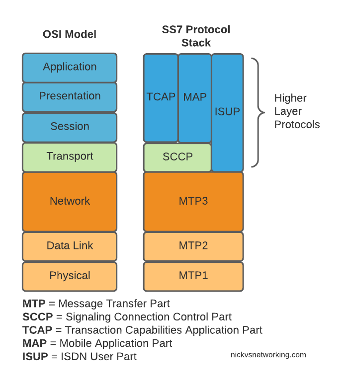
Here’s the layers of SS7 loosely mapped onto the OSI model (SS7 predates the OSI model as well):
OSI Model (Left) and SS7 Protocol Stack (Right)
We do have a few layers to play with here, and we’ll get into them all in depth as we go along, but a brief introduction to the underlying layers:
MTP 1 – Message Transfer Part 1
This is our physical layer. In this past this was commonly E1/T1 lines.
It’s responsible for getting our 1s and 0s from one place to another.
MTP 2 – Message Transfer Part 2
MTP2 is responsible for the data link layer, handling reliable transfer of data, in sequence.
MTP 3 – Message Transfer Part 3
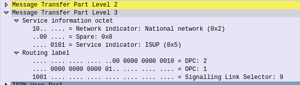
The MTP3 header contains an Originating and a Destination Point Code.
These point codes can be thought of as like an IP Address; they’re used to address the source and destination of a message. A “Point Code” is the unique address of a SS7 Network element.
MTP3 header showing the Destination Point Code (DPC) and Origin Point Code (OPC) on a National Network, carrying ISUP traffic
Every message sent over an SS7 network will contain an Origin Point Code that identifies the sender, and a Destination Point Code that identifies the intended recipient.
This is where we’ll bash around at the start of this course, setting up Linksets to allow different devices talking to each other and addressing each other via Point Codes.
The MTP3 header also has a Service Indicator flag that indicates what the upper layer protocol it is carrying is, like the Protocol indicator in IPv4/IPv6 headers.
A Signaling Link Selector indicates which link it was transported over (did I mention we can join multiple links together?), and a Network Indicator for determining if this is signaling is at the National or International level.
TUP/MAP/SCCP/ISUP
These are the “higher-layer” protocols. Like FTP sits on top of TCP/IP, a SS7 network can transport these protocols from their source to their destination, as identified by the Origin Point Code (OPC), to the Destination Point Code (DPC), as specified in the MTP3 header.
We’ll touch on these protocols more as we go on. SCCP has it’s own addressing on top of the OPC/DPC (Like IP has IP Addressing, but TCP has port numbers on top to further differentiate).
Why learn SS7 today?
SS7 and SIGTRAN are still widely in use in the telco world, some of it directly, other parts derived / evolved from it.
So stick around, things are about to get interesting!