The gray telecom cabinets and pillars can be seen in suburbs across Australia, along rail corridors and even overseas.
But what do they do? What’s the difference between a pillar and a cabinet? Are they still used today? What’s inside? Why are they such an important part of the network?
What are they?
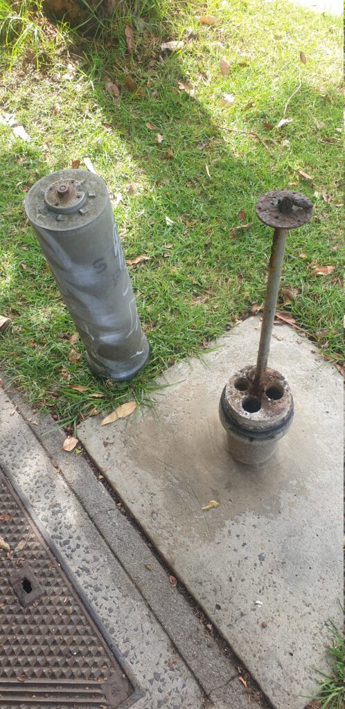
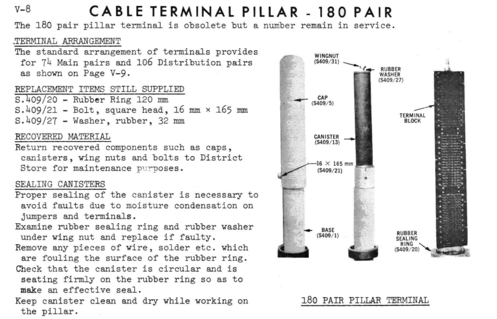
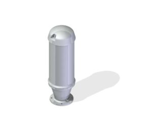
In a nutshell, they’re weatherproof (if properly cared for) enclosures for cross connecting (jumpering) cables.
This means that rather than doing the jumpering / cross connecting services in a dirty pit, a cabinet can be opened and the connection made quickly, in a clean, easily accessed, above ground housing.
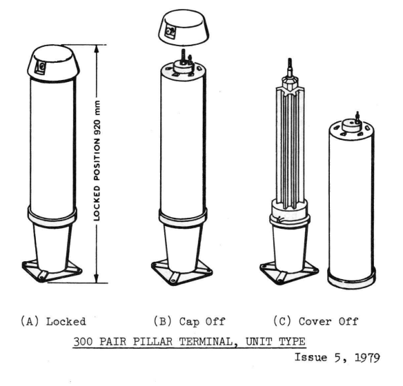
They utilise a really clever design, that was the result of a competitive design process in the 1950s.
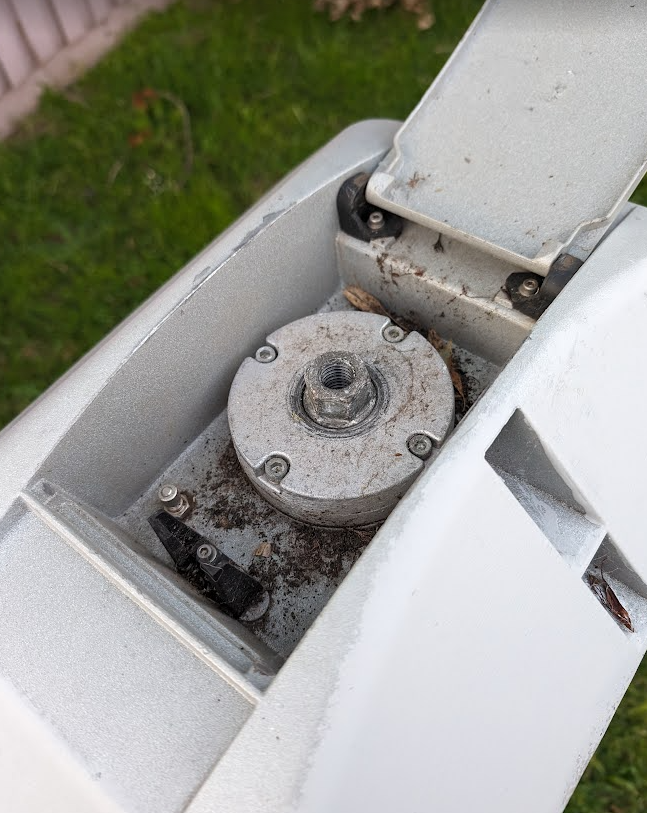
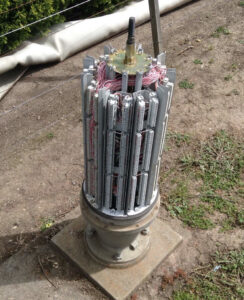
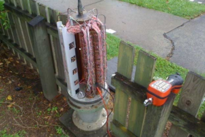
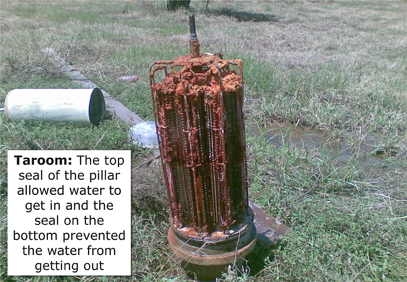
The schrader valve (bike valve) at the top allows the units to remain pressurized, this means in areas subject to flooding or for pressurised cables, the pillar remains water tight ( although the practice of sealing them again with air isn’t very common anymore).
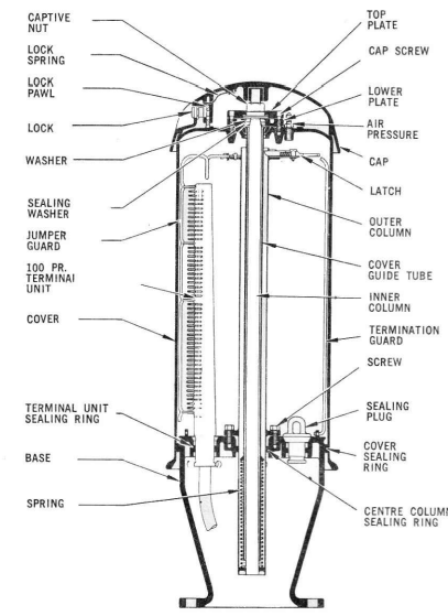
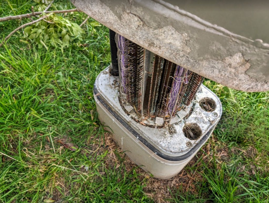
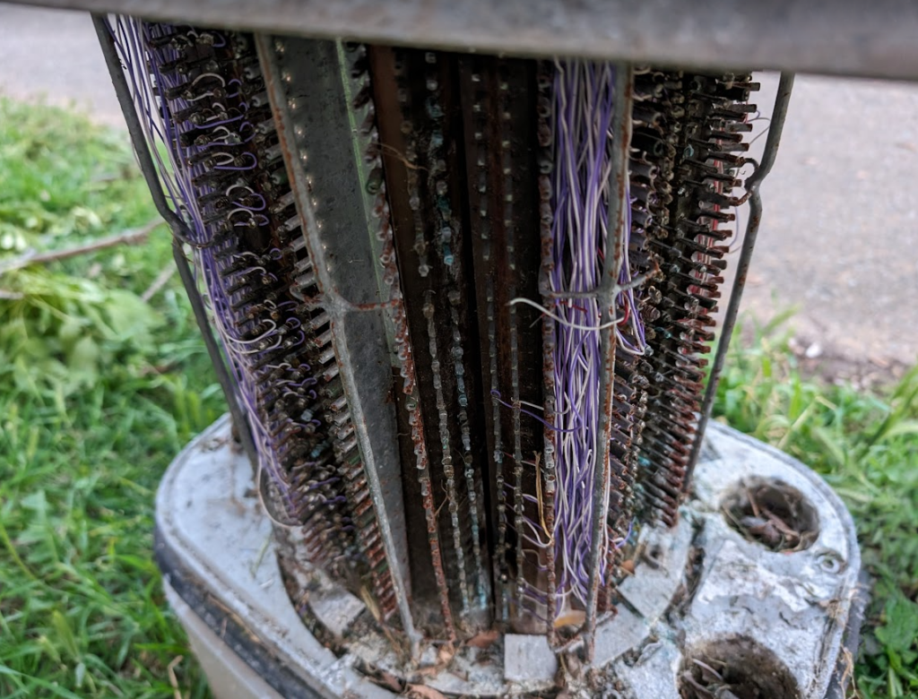
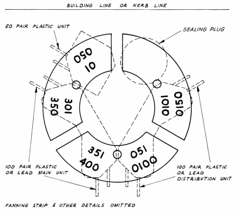
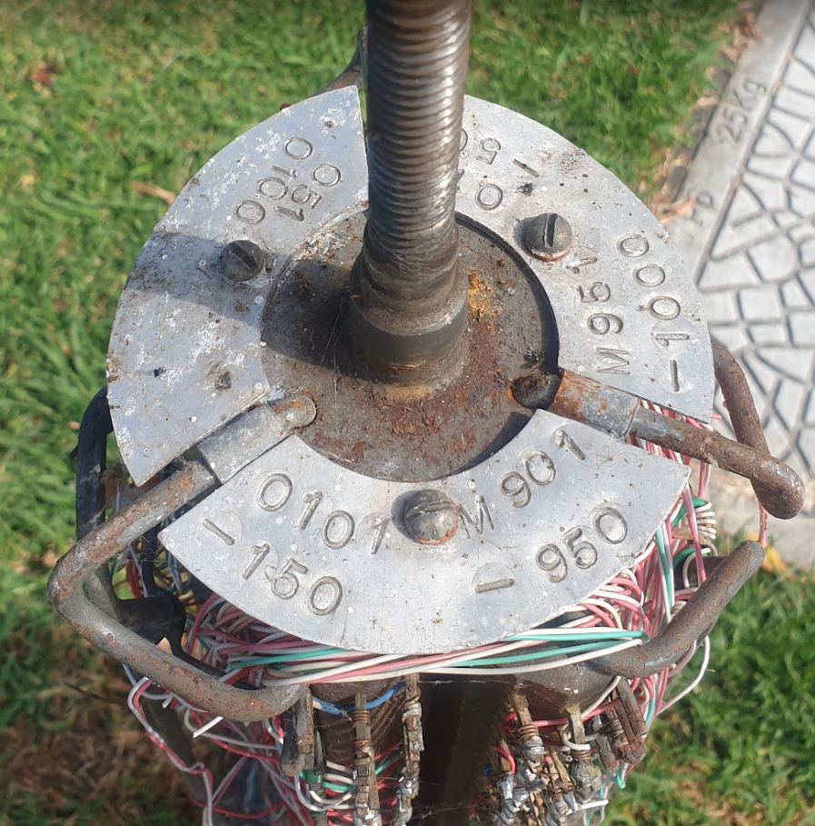
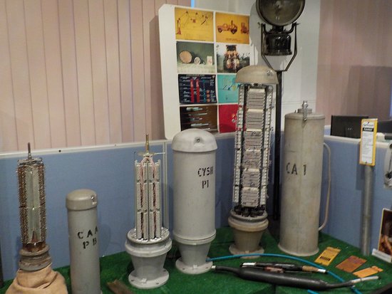
When the aluminum top plate is unlocked and spun off the threaded fitting, the linesworker can unscrew the big nut on top, and lift up the cover, which locks open at the top, revealing the terminal units (either solder tag blocks or Krone blocks) inside the unit.
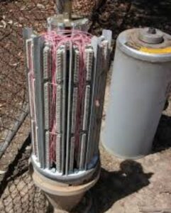

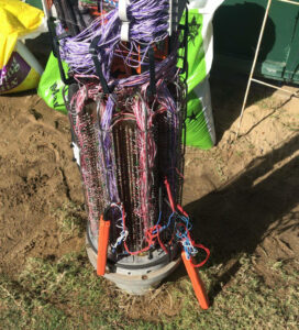
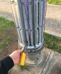
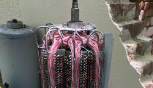
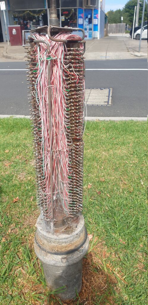
Jumpering a service is just a matter of opening up the cabinet, finding the A side and the B side, and running jumper wire through the built in cable management loops from one side to the other.
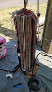
Each of the Terminal Units is a pre-terminated strip with a few meters of tail, which is fed through the base of the pillar to a nearby pit where they can join 1 to 1, out onto the underground cables, this means the units can be upgraded for additional capacity as needed.
Why were they needed?
- Cables are expensive. We want to minimize excess unused pairs and use the existing pairs with maximum flexibility and efficacy
- Opening joints costs time, money, and risks disturbing other services. We want to avoid opening joints
- Troubleshooting is also time consuming and costly. A convenient test point is needed for isolating where in a cable a fault lies. (Main Cable, Distribution Cable, etc)
- Easily use gas/air filled cables, without having to constantly open and reseal cables them to splice in new joins / jumpers
Cabinet vs Pillar
Cabinets and Pillars look the same, but the hints as to their purpose are in their location and what’s sprayed on them in faded paint.
Pillars are used for cross-connecting main cables (“M” Pair from the exchange) with distribution cables (to subscribers “O” pairs which run down the street to the pit in the front of your house).
Pillars are generally stenciled with a “P” and an number, or just the DA (Distribution Area) number.
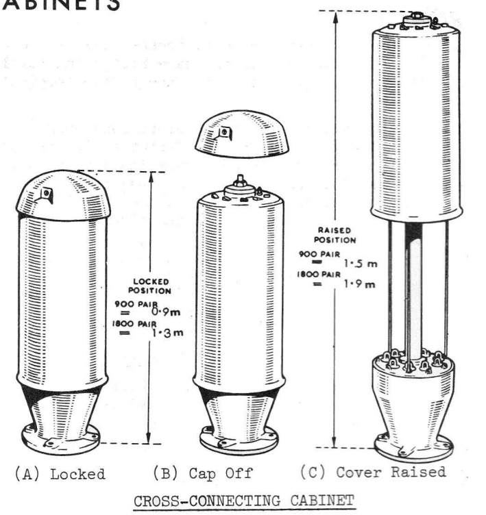
Cabinet are a more flexible setup where you can connect cables between Pillars, akin to a root & branch approach.
Cabinets cross connect Main Cables (“M” pair to the exchange), with Branch Cables (“B” Pair from the Cabinet to Pillar) and Distribution cables (“O” pair to the customer).
Cabinets are stenciled with the prefix “CA” and a number, and exist in the 900 and 1800 pair variants, where one is just taller than the other.
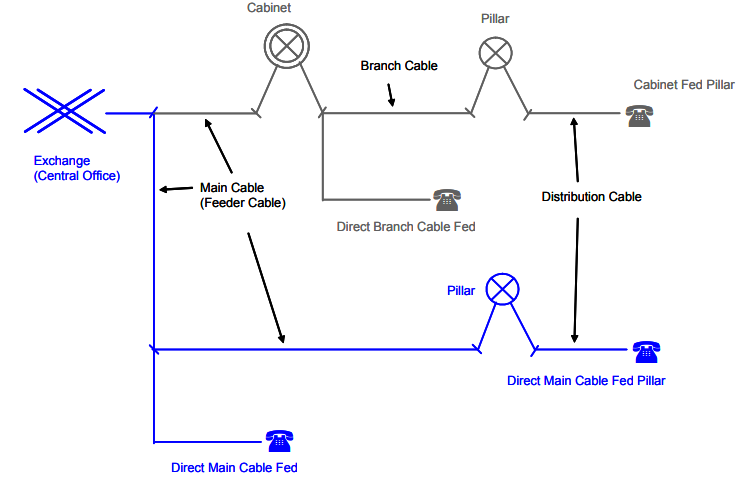
This means the distribution can go via a Cabinet to the Pillar to the Customer, as shown in the top /grey lines in the diagram.
- Exchange Main Cables (Main Cables / M-Pairs) go to Cabinets
- Cabinets connect to Pillars (Branch Cables / B-Pairs)
- Pillars connect (Distribution Cables / O-Pairs) that run through the pits outside houses
- Inside the Openable Joint in the pit is used to connect the lead in cable from a subscriber’s premises
Alternatively, the Cabinet may be bypassed and a direct cable goes between the Exchange and the Pillar, in that scenario it looks like the one show in blue lines on the diagram.
- Exchange Main Cables (Main Cables / M-Pairs) go to Pillar
- Pillars connect (Distribution Cables / O-Pairs) that run through the pits outside houses
- Inside the Openable Joint in the pit is used to connect the lead in cable from a subscriber’s premises
The Cabinet to Pillar model fell out of favor due to its increased complexity.
While it was cheaper to deploy the network using cabinets that cascaded down to feed pillars (you would only have to install enough cable for the “here and now” and could add additional Main & Branch cables as needed in a targeted manner) the move to outsourced lineswork for Telecom found that any increased complexity, led to additional operational cost that outweighed the capital savings
Use in the “Modern” Copper Customer Access Network
Pillars are still used in areas of Australia where NBNco have deployed Fibre to the Node.
NBN adds a row of X-Pairs (VDSL) and C-Pairs (Channel) to the pillar, which connect into the FTTN nodes themselves.
This means a customer with a traditional POTS line (M-Pair from the Exchange, C-Pair from the Cabinet to the Pillar, O-Pair from the Pillar to the Pit, and then the lead-in into their property) has the O-Pair and C-Pair buzzed out on the pillar, and then routed through the X-Pair and the C-Pair on the Node.
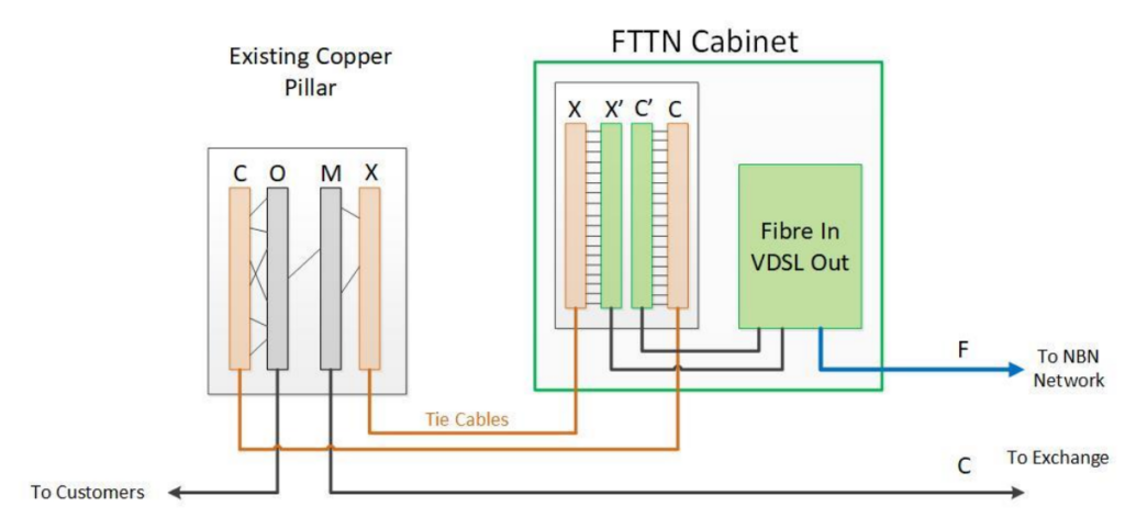
This puts the DSLAM in the Alcatel ISAM inline with the customer’s existing copper loop to the Exchange. The main cable comes from the exchange onto the M-Pair blocks in the Pillar, is jumpered onto the X-Pairs which go through the DSLAM, and come out as C-Pairs back onto the pillar. The C-Pair is then jumpered back to the Customer’s O-Pair and bingo, the FTTN cabinet is inline with the copper loop.
However as the PSTN services get dropped, the Main / M-Pair to the exchange can eventually be removed and the cables removed, meaning the connection just goes from the C pair for VDSL out into the O pair to the customer.
As part of the NBN migration some pillars were upgraded to include IDC / Punch Down blocks, and a rectangular version of the pillar was introduced.
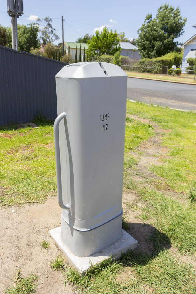
Oddly, these rectangular covers, do not have rectangular units inside, but rather cylindrical ones, just like the pillars of old.
This does fix the missing lids issue – The lid is captive, but I’m not sure what other design improvements this introduces – if anyone has the insight I’d be keen to hear it!