So I’ve been waxing lyrical about how cool in the NRF is, but what about how it’s secured?
A matchmaking service for service-consuming NFs to find service-producing NFs makes integration between them a doddle, but also opens up all sorts of attack vectors.
Theoretical Nasty Attacks (PoC or GTFO)
Sniffing Signaling Traffic:
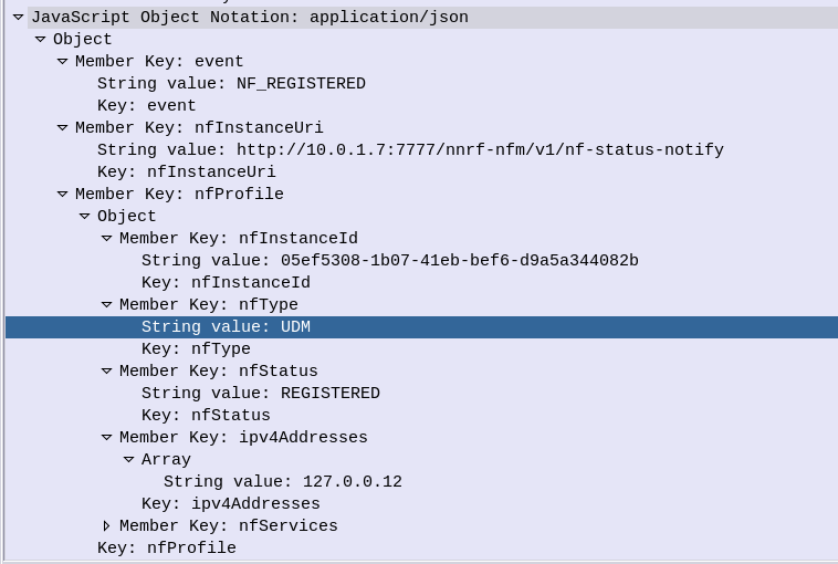
A malicious actor could register a fake UDR service with a higher priority with the NRF. This would mean UDR service consumers (Like the AUSF or UDM) would send everything to our fake UDR, which could then proxy all the requests to the real UDR which has a lower priority, all while sniffing all the traffic.
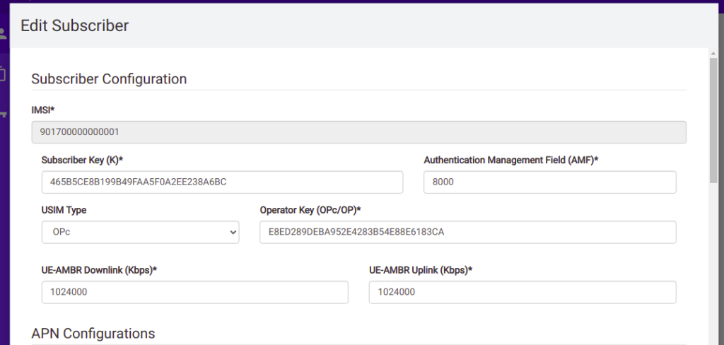
Stealing SIM Credentials:
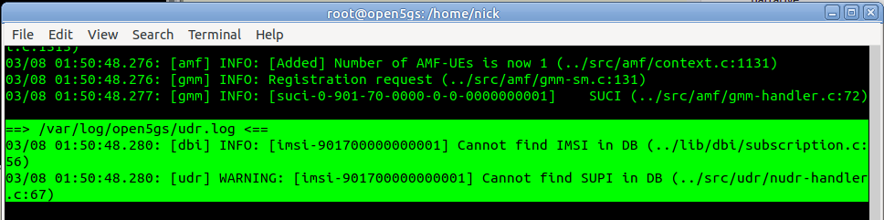
Brute forcing the SUPI/IMSI range on a UDR would allow the SIM Card Crypto values (K/OP/Private Keys) to be extracted.
Sniffing User Traffic:
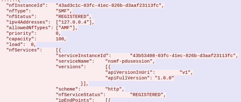
A dodgy SMF could select an attacker-controlled / run UPF to sniff all the user traffic that flows through it.
Obviously there’s a lot more scope for attack by putting nefarious data into the NRF, or querying it for data gathering, and I’ll see if I can put together some examples in the future, but you get the idea of the mischief that could be managed through the NRF.
This means it’s pretty important to secure it.
OAuth2
3GPP selected to use common industry standards for HTTP Auth, including OAuth2 (Clearly lessons were learned from COMP128 all those years ago), however OAuth2 is optional, and not integrated as you might expect. There’s a little bit to it, but you can expect to see a post on the topic in the next few weeks.
3GPP Security Recommendations
So how do we secure the NRF from bad actors?
Well, there’s 3 options according to 3GPP:
Option 1 – Mutual TLS
Where the Client (NF) and the Server (NRF) share the same TLS info to communicate.
This is a pretty standard mechanism to use for securing communications, but the reliance on issuing certificates and distributing them is often done poorly and there is no way to ensure the person with the certificate, is the person the certificate was issued to.
3GPP have not specified a mechanism for issuing and securely distributing certificates to NFs.
Option 2 – Network Domain Security (NDS)
Split the network traffic on a logical level (VLANs / VRFs, etc) so only NFs can access the NRF.
Essentially it’s logical network segregation.
Option 3 – Physical Security
Split the network like in NDS but a physical layer, so the physical cables essentially run point-to-point from NF to NRF.
Thoughts?
What’s interesting is these are presented as 3 options, rather than the layered approach.
OAuth2 is used, but
Summary
TS 133 501 – 13.3.1 Authentication and authorization between network functions and the NRF
NRF and NF shall authenticate each other during discovery, registration, and access token request. If the PLMN uses
protection at the transport layer as described in clause 13.1, authentication provided by the transport layer protection
solution shall be used for mutual authentication of the NRF and NF.
If the PLMN does not use protection at the transport layer, mutual authentication of NRF and NF may be implicit by
NDS/IP or physical security (see clause 13.1).
When NRF receives message from unauthenticated NF, NRF shall support error handling, and may send back an error
message. The same procedure shall be applied vice versa.
After successful authentication between NRF and NF, the NRF shall decide whether the NF is authorized to perform
discovery and registration.
In the non-roaming scenario, the NRF authorizes the Nnrf_NFDiscovery_Request based on the profile of the expected
NF/NF service and the type of the NF service consumer, as described in clause 4.17.4 of TS23.502 [8].In the roaming
scenario, the NRF of the NF Service Provider shall authorize the Nnrf_NFDiscovery_Request based on the profile of
the expected NF/NF Service, the type of the NF service consumer and the serving network ID.
If the NRF finds NF service consumer is not allowed to discover the expected NF instances(s) as described in clause
4.17.4 of TS 23.502[8], NRF shall support error handling, and may send back an error message.
NOTE 1: When a NF accesses any services (i.e. register, discover or request access token) provided by the NRF ,
the OAuth 2.0 access token for authorization between the NF and the NRF is not needed.