It was the best of times, it was the worst of times. It was the age of wisdom, it was the age of foolishness. It was the epoch of belief, it was the epoch of incredulity. It was the season of Light, it was the season of Darkness. It was the spring of hope, it was the winter of despair.
A tale of two Cities
When Dickens wrote of Doctor Manette in the 1859, I doubt his intention was to write about the repeating history of RAN fronthaul standards – but I can’t really say for sure.
Setting the Scene
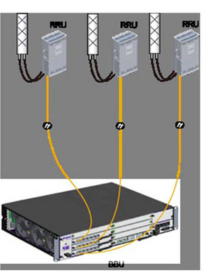
Our story starts with introducing CPRI (Common Public Radio Interface) interface, having been imprisoned in the Bastille of vendor lock in for the better part of twenty years.
Think of CPRI is less of a hard interoperable standard and more like how the Italian and French languages are both derived from Latin; it doesn’t mean that the two languages are the same, but they’ve got the same root and may share some common words and structures.
In practice this means that taking an Ericsson Radio and plugging it into a Huawei Baseband simply won’t work – With CPRI you must use the same vendor for the Baseband and the Radios.
The Unexpected Plot Twist
“Nuts to this” the industry said after being stuck locked between the same radios and baseband for years; we should create a standard so we can mix and match between radio vendors, and even standardize some other stuff that’s been bothering us, so we’ll have a happy world of interoperability.

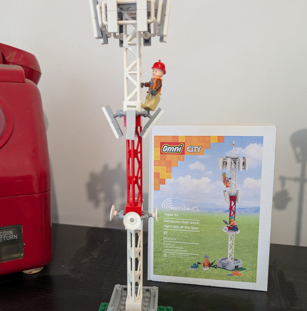
With kit created that followed this standard, we’d be able to take components from vendor A, B & C, and fit them together like Lego, saving you some money along the way and giving you’ve got a working solution made of “best of breed” components, where everything is interoperable.
So the industry created a group to chart a path for a better tomorrow by standardizing these interfaces.
The group had many industry heavyweights like Nokia, NEC, LG, ZTE and Samsung joining.
The key benefits espoused on their website:
An open market will substantially reduce the development effort and costs that have been traditionally associated with creating new base station product ranges. The availability of off-the-shelf base station modules will enable manufacturers to focus their development efforts on creating further added value within the base station, encouraging greater innovation and more cost-effective products. Furthermore, as product development cycles will be reduced, new base station functions will become available on the market more quickly.
Mission statement of the group
In addition to being able to mix and match radios and basebands from different vendors, the group defined standards for centralized baseband, and interoperable standards, to allow a multi-vendor ecosystem to flourish.
And here’s the plot twist – The text above, was not written about OpenRAN, and it was not written about the benefits of eCPRI.
It was written about Open Base Station Architecture Initiative (OBSAI) and it was written 22 years ago.
*record screech sound*

Standards War you’ve never heard of: OBSAI vs CPRI
When OBSAI was defined it was not without competition; there was another competing fronthaul standard; that’s right, the mustache twirling lowlife from earlier in the story – CPRI.
Supported by Huawei, Nortel, NEC & Ericsson (among others), CPRI took a “gentle parenting” approach to the standards world, in contrast to OBSAI.
Instead of telling all the vendors to agree on an interoperable front haul standard, CPRI just encouraged everyone to implement what their heart told them and what felt right to them.
As it happened, the industry favored the CPRI approach.
If a vendor wanted to add a new “word” in their CPRI “language” to add a new feature, they just went ahead and added it – It didn’t require anyone else to agree with them or changes to a common standard used by the industry, vendors could talk to the kit they made how they wanted.
CPRI has been the defacto non-standard used by all the big kit vendors for the past ~10 years.
The Death of OBSAI & the Birth of OpenRAN’s eCPRI
Why haven’t you heard of OBSAI? Why didn’t the OBSAI standard just serve as the basis for eCPRI – After all the last OBSAI release was less than 5 years before TIP started working on eCPRI publicly.

Did a schism over “uplink performance improvement” options lead to “irreconcilable differences” between parties leading to the breakup of the OBSAI group?
Nope.
Customers (MNOs) didn’t buy OBSAI based equipment in measurably larger quantities than CPRI kit. That’s it.
This meant the vendors invested less in paying teams to further develop the standards, the OBSAI group met less frequently, and in the end, member vendors didn’t bother adding support for OBSAI to new equipment and just used the easier and more flexible CPRI option instead.
At some point someone just stopped paying for the domain renewal and that was it, OBSAI was no more.
This is how the standards body ends, not with a bang, but with a whimper.
T.S. Elliot’s writings on the death of obsai
Those who do not learn from history…
The goals of the OBSAI Group and OpenRAN working groups are almost identical, so what lessons did Marconi, Motorola and Alcatel learn as members of OBSAI that other vendors could learn about OpenRAN strategy?
There are no mentions of OBSAI in any of the information published by OpenRAN advocates, and I’m wondering if folks aren’t aware that history tends to repeat and are ignorant to what came before it, or they’re just not learning lessons from the past?
So what can the OpenRAN industry learn from OBSAI?
Being a nerd, I started detailing the technical challenges, but that’s all window dressing; The biggest hurdle facing CPRI vs eCPRI are the same challenges OBSAI vs CPRI faced a decade prior:
To be relevant, OpenRAN kit has to be demonstrably better than what we have today AND provide a tangible cost saving.
OBSAI failed at achieving this, and so failed to meet it’s other more noble goals.
[At the time of writing this at least] I’d contend that neither of those two criteria have been met by OpenRAN.
What does the future hold for OpenRAN?
Looking into the crystal ball, will OpenRAN and eCPRI go the way of OBSAI, or will someone keep the OpenRAN dream alive?
Today, we’re still seeing the MNOs continue to provide tokenistic investment in OpenRAN. But being a cynic, I’d say the MNOs are feigning interest in OpenRAN products because it’s advantageous for them to do so.
The threat of OpenRAN has proven to be a great stick to beat the traditional vendors with to force them to lower their prices.
Think about the $14 billion USD Ericsson deal with AT&T, if chucking a few million at OpenRAN pilots / trials lead to AT&T getting even a 0.1% reduction in what they’re paying Ericsson, then the numbers would have worked out well in AT&Ts favor.
From the MNOs perspective, the cost to throw the odd pilot or trial to a hungry OpenRAN vendor to keep them on the hook is negligible, but the threat of OpenRAN provides leverage and bargaining power every time it’s contract renewal time with the big RAN vendors.
Already we’ve seen all the traditional RAN vendors move to neutralize this threat by introducing “OpenRAN compatible” equipment and talking up their commitment to openness.
This move by the RAN vendors takes this sting out of the OpenRAN threat, and means MNOs won’t have much reason to continue supporting OpenRAN.
This leaves the remaining OpenRAN vendors like Miss Havisham, forever waiting in their proverbial wedding dresses, having being left at the altar.
Okay, I’m mixing my Dickens’ references here, but it was too good not to.
Appendix
I’ve been enjoying writing more analysis than just technical content, let me know if this is something you’re interested in seeing more of.
I’ve been involved in two big OpenRAN integration projects, both of which went poorly and probably tainted my perspective. Enough time has passed to probably write up how it all went with the vendor names removed, but that’s a post for another time!
If you wanted to learn more about OBSAI Archive.org has their old website available for reading.