Tag Archives: RTP

RTPengine – Installation & Configuration (Ubuntu 20.04 / 22.04)

I wrote a post a few years back covering installing RTPengine on Ubuntu (14.04 / 18.04) but it doesn’t apply in later Ubuntu releases such as 20.04 and 22.04.

To make everyone’s lives easier; David Lublink publishes premade repos for Ubuntu Jammy (22.04) & Focal (20.04).

Note: It looks like Ubuntu 23.04 includes RTPengine in the standard repos, so this won’t be needed in the future.

sudo add-apt-repository ppa:davidlublink/rtpengine
sudo apt update
sudo apt-get install ngcp-rtpengine

The Ambient Capabilities in the systemctl file bit me,

Commenting out :

#AmbientCapabilities=CAP_NET_ADMIN CAP_SYS_NICE

In /lib/systemd/system/ngcp-rtpengine-daemon.service and then reloading the service and restarting and I was off and running:

systemctl daemon-reload
systemctl restart rtpengine

Getting it Running

Now we’ve got RTPengine installed let’s setup the basics,

There’s an example config file we’ll copy and edit:

vi /etc/rtpengine/rtpengine.conf

We’ll uncomment the interface line and set the IP to the IP we’ll be listening on:

Once we’ve set this to our IP we can start the service:

systemctl restart rtpengine

All going well it’ll start and rtpengine will be running.

You can learn about all the startup parameters and what everything in the config means in the readme.

Want more RTP info?

If you want to integrate RTPengine with Kamailio take a look at my post on how to set up RTPengine with Kamailio.

For more in-depth info on the workings of RTP check out my post RTP – More than you wanted to Know

Kamailio Bytes – Extracting SDP Parameters with Kamailio

So the other day I needed to extract the IP and Port parameters from an SDP body – Not the whole line mind, but the values themselves.

As with so many things in Kamailio, there’s a lot of ways to achieve an outcome, but here’s how I approached this problem.

Using the SDPops module we can get a particular line in the SDP, for example, we can get the media line with:

#Get SDP line starting with m= and put it into AVP $avp(mline)
sdp_get_line_startswith("$avp(mline)", "m=")
#Print value of $avp(mline)
xlog("m-line: $avp(mline)\n");

This gets us the line, but now we need to extract the data, in the example from the screenshot the M line has the value:

m=audio 4002 RTP/AVP 8 101

But we only want the port from the M line.

This is where I’ve used the Kamailio Dialplan module and regex to extract the port from this line.

With a fairly simple regex pattern, we can get a group match for the Port from the m= line.

So I took this regular expression, and put it into the Kamailio Dialplan database with dialplan ID 400 for this example:

INSERT INTO `dialplan` VALUES (4,400,10,1,'m=audio (\\d*)',0,'m=audio (\\d*)','\\1','SDP M Port Stripper');

Now using Dialplan ID 400 we can translate an inputted m= SDP line, and get back the port used, so let’s put that into practice:

        if(sdp_get_line_startswith("$avp(mline)", "m=")) {
            xlog("m-line: $avp(mline)\n");
            xlog("raw: $avp(mline)");
            xlog("Extracting Port from Media Line");
            dp_translate("400", "$avp(mline)/$avp(m_port_b_leg)");
            xlog("Translated m_port_b_leg is: $avp(m_port_b_leg)");
        }

Now we have an AVP called $avp(m_port_b_leg) which contains the RTP Port from the SDP.

Now we’ve got a few other values we might want to get, such as the IP the RTP is to go to, etc, we can extract this in the same way, with Dialplans and store them as AVPs:

        #Print current SDP Values and store as Vars
        if(sdp_get_line_startswith("$avp(mline)", "m=")) {
            xlog("m-line: $avp(mline)\n");
            xlog("raw: $avp(mline)");
            xlog("Extracting Port from Media Line");
            dp_translate("400", "$avp(mline)/$avp(m_port_b_leg)");
            xlog("Translated m_port_b_leg is: $avp(m_port_b_leg)");
        }

        if(sdp_get_line_startswith("$avp(oline)", "o=")) {
            xlog("o-line: $avp(oline)\n");
            dp_translate("401", "$avp(oline)/$avp(o_line_port_1)");
            xlog("O Line Port 1: $avp(o_line_port_1)");
            dp_translate("402", "$avp(oline)/$avp(o_line_port_2)");
            xlog("O Line Port 2: $avp(o_line_port_2)");
            dp_translate("403", "$avp(oline)/$avp(o_ip_b_leg)");
            xlog("O IP: $avp(o_ip_b_leg)");
        }

And all the Regex you’ll need:

INSERT INTO `dialplan` VALUES 
(4,400,10,1,'m=audio (\\d*)',0,'m=audio (\\d*)','\\1','SDP M Port Stripper'),
(5,401,10,1,'o=[^ ]* (\\d*) (\\d*) IN IP4 (\\d*.d*.\\d*.\\d*)',0,'o=[^ ]* (\\d*) (\\d*) IN IP4 (\\d*.d*.\\d*.\\d*)','\\1','O Port 1'),
(6,402,10,1,'o=[^ ]* (\\d*) (\\d*) IN IP4 (\\d*.d*.\\d*.\\d*)',0,'o=[^ ]* (\\d*) (\\d*) IN IP4 (\\d*.d*.\\d*.\\d*)','\\2','O Port 2'),
(7,403,10,1,'o=[^ ]* (\\d*) (\\d*) IN IP4 (\\d*.d*.\\d*.\\d*)',0,'o=[^ ]* (\\d*) (\\d*) IN IP4 (\\d*[.]\\d*[.]\\d*[.]\\d*)','\\3','O IP');


The case for Header Compression in VoIP/VoLTE

On a PCM (G.711) RTP packet the payload is typically 160 bytes per packet.

But the total size of the frame on the wire is typically ~214 bytes, to carry a 160 byte payload that means 25% of the data being carried is headers.

This is fine for VoIP services operating over fixed lines, but when we’re talking about VoLTE / IMS and the traffic is being transferred over Radio Access Networks with limited bandwidth / resources, it’s important to minimize this as much as possible.

IMS uses the AMR codec, where the RTP payload for each packet is around 90 bytes, meaning up to two thirds of the packet on the wire (Or in this case the air / Uu interface) is headers.

Enter Robust Header Compression which compresses the headers.

Using ROHC the size of the headers are cut down to only 4-5 bytes, this is because the IPv4 headers, UDP headers and RTP headers are typically the same in each packet – with only the RTP Sequence number, RTP timestamp IPv4 & UDP checksum and changing between frames.

SIP SDP – ptime

ptime is the packetization timer in VoIP, it’s set in the SDP message and defines the length of each RTP packet that’s sent;

This gives the length of time in milliseconds represented by the media in a packet. This is probably only meaningful for audio data, but may be used with other media types if it makes sense. It should not be necessary to know ptime to decode RTP or vat audio, and it is intended as a recommendation for the encoding/packetisation of audio. It is a media-level attribute, and it is not dependent on charset.

RFC 4556 – SDP: Session Description Protocol, Section 6
SDP body showing ptime value of 20ms

What it’s all about

A lower ptime value leads to more packet per second, while longer ptime leads to fewer packets per second.

In a Toll Quality (TDM) network 8000 samples per second are taken, this is reflected in PCM (Pulse Code Modulation) encoding of the data, see in PCMA / G.711 a-law for example.

But if each of these 8,000 samples per second were sent on an individual packet, we’d be seeing a huge number of tiny RTP packets where the header is a lot larger than the payload.

Instead endpoints generally wait until they’ve got a certain number of theses samples and then send them at once, every X milliseconds as defined by the ptime value.

  • A ptime of 1000ms would mean 1 packet per second.
  • A ptime of 20ms would mean 50 packets per second.
  • A ptime of 50ms would mean 20 packets per second.

ptime headaches

Some VoIP endpoints have issues with varied ptime (*cough Cisco SPA series cough*), and if you’re interconnecting with other carrier networks you have no real control as to what ptime endpoints use (except if you have a B2Bua that can resample / restuff the packets, or you use maxptime which really just limits more than fixes) so it’s worth understanding well.

International carrier trunks often have higher ptime values as they're often dealing with lower quality links, so they want to cut down the packets per second and often have jitter buffers in place to compensate for poor quality links.

RFC4566 (the second version of SDP) introduced the maxptime value.

This optional header in the SDP body allows an endpoint to specify the maximum ptime value it supports.

Older endpoints often don’t have much memory or processing power, so have very small buffers to store the received audio in before playing it to the user, and store the audio to be transmitted before sending it down the wire.

Mismatched ptime or a ptime that’s out of bounds for one endpoint can lead to some strange issues. Often an endpoint will ring, answer the call and even get a 200 OK, but immediately followed by a BYE from the incompatible end instead of an ACK.

In the initial INVITE ptime is not mandatory, meaning you may not know the caller has limits to the ptime values they can support, and the endpoint hangs up the calls straight after the 200 OK.

Identifying these issues may take some time, but here’s some good places to look:

  • SDP ptime value on INVITE and 200 OK
  • Time between RTP packets
  • Timestamp difference between RTP packets

Although it seems pretty self evident, if your endpoint only supports up to 20ms ptime, set the maxptime header to 20ms. You’d be surprised how often this isn’t the case.

You can read more about SDP on my Overview of SDP post and the RFC – RFC4566. You can lean about manipulating SDP headers in Kamailio in my post on SDPops.

Virtualized Transcoding Dimensioning

A seemingly simple question is how many concurrent calls can a system handle.

Sadly the answer to that question is seldom simple and easy to say, even more so when we talk about transcoding.

Transcoding is the process of taking a media stream encoded in one codec (format) and transferring it to a different codec (hence trans-coding).

This can be a very resource intensive process, so there’s a large number of hardware based solutions (PCI cards / network devices) that use FGPAs and clever processor arrangements to handle the transcoding. These products are made by a multitude of different vendors but are generally called hardware transcoders.

Today we’ll talk a bit about software based transcoding, and how many concurrent calls you can transcode on common VM configurations.

These stats will translate fairly well to their dedicated hardware counterparts, but a VM provides us with a consistent hardware environment so makes it a bit easier.

For these tests I created the baseline VM to run in VMWare Workstation with the below settings:

We’ll be transcoding using RTPengine, which recently added transcoding capabilities, so I set that up as per my post on setting up RTPengine for Transcoding.

Next I setup some SIPp scenarios to simulate call loads, from G.711 a-law to G.711 u-law (the simplest of transcoding (well re-compounding)) and used glances to get the max CPU usage and logged the results.

PCMA to PCMU (Re-companding)

PCMA to PCMU

RTPengine fared significantly better than I expected, I stopped at 150 concurrent transcoding sessions as that’s when call quality was really starting to degrade, but I was still achieving MOS of 4.3+ up to 130 concurrent sessions.

For what I needed to do, running this in a virtualised environment allowed 150 transcoding sessions before the MOS started to drop and call quality was adversely affected. Either way I was pretty amazed at how efficiently RTPengine managed to handle this.

Transcoding from one codec to a different codec was a different matter, and I’ll post the results from that another day.

If you want to learn more about RTPengine have a read of my other posts on RTPengine, that cover Installing and configuring RTPengine, using RTPengine with Kamailio, transcoding with RTPengine and scaling with RTPengine over geographic areas.

RTPengine Python API Calls via ng Control Protocol

RTPengine has an API / control protocol, which is what Kamailio / OpenSER uses to interact with RTPengine, called the ng Control Protocol.

Connection is based on Bencode encoded data and communicates via a UDP socket.

I wrote a simple Python script to pull active calls from RTPengine, code below:

#Quick Python library for interfacing with Sipwise's fantastic rtpengine - https://github.com/sipwise/rtpengine
#Bencode library from https://pypi.org/project/bencode.py/ (Had to download files from webpage (PIP was out of date))

import bencode
import socket
import sys
import random
import string

sock = socket.socket(socket.AF_INET, socket.SOCK_DGRAM)
server_address = ('188.0.169.13', 2224)     #Your server address

cookie = "0_2393_6"
data = bencode.encode({'command': 'list'})

message = str(cookie) + " " + str(data)
print(message)


sent = sock.sendto(message, server_address)

print('waiting to receive')
data, server = sock.recvfrom(4096)
print('received "%s"' % data)
data = data.split(" ", 1)       #Only split on first space
print("Cookie is: " + str(data[0]))
print("Data is: " + str(bencode.decode(data[1])))
print("There are " + str(len(bencode.decode(data[1])['calls'])) + " calls up on RTPengine at " + str(server_address[0]))
for calls in bencode.decode(data[1])['calls']:
    print(calls)
    cookie = "1_2393_6"
    data = bencode.encode({'command': 'query', 'call-id': str(calls)})
    message = str(cookie).encode('utf-8') + " ".encode('utf-8') + str(data).encode('utf-8')
    sent = sock.sendto(message, server_address)
    print('\n\nwaiting to receive')
    data, server = sock.recvfrom(8192)

    data = data.split(" ", 1)       #Only split on first space
    bencoded_data = bencode.decode(data[1])

    for keys in bencoded_data:
        print(keys)
        print("\t" + str(bencoded_data[keys]))

sock.close()

NBNco Australia network map

Kamailio Bytes – Routing to geo local RTPengine Instances with Kamailio

I’m a big fan of RTPengine, and I’ve written a bit about it in the past.

Let’s say we’re building an Australia wide VoIP network. It’s a big country with a lot of nothing in the middle. We’ve got a POP in each of Australia’s capital cities, and two core softswitch clusters, one in Melbourne and one in Sydney.

These two cores will work fine, but a call from a customer in Perth, WA to another customer in Perth, WA would mean their RTP stream will need to go across your inter-caps to Sydney or Melbourne only to route back to Perth.

That’s 3,500Km each way, which is going to lead to higher latency, wasted bandwidth and decreased customer experience.

What if we could have an RTPengine instance in our Perth POP, handling RTP proxying for our Perth customers? Another in Brisbane, Canberra etc, all while keeping our complex expensive core signalling in just the two locations?

RTPengine to the rescue!

Preparing our RTPEngine Instances

In each of our POPs we’ll spin up a box with RTPengine,

We’d set it up in the way outlined in this post,

The only thing we’d do differently is set the listen-ng value to be 0.0.0.0:2223 and the interface to be the IP of the box.

By setting the listen-ng value to 0.0.0.0:2223 it’ll mean that RTPengine’s management port will be bound to any IP, so we can remotely manage it via it’s ng-control protocol, using the rtpengine Kamailio module.

Naturally you’d limit access to port 2223 only to allowed devices inside your network.

Adding Multiple RTP Engines to Kamailio Database

After adding database functionality to our Kamailio instance as we covered in this post, we’ll just need to add the follow lines to our config:

loadmodule "rtpengine.so"
modparam("rtpengine", "db_url", DBURL)
modparam("rtpengine", "table_name", "rtpengine")
modparam("rtpengine", "setid_avp", "$avp(setid)")

Next we’ll need to add the details of each of our RTP engine instances to MySQL, I’ve used a different setid for each of the RTPengines. I’ve chosen to use the first digit of the Zipcode for that state (WA’s Zipcodes / Postcodes are in the format 6xxx while NSW postcodes are look like 2xxx), we’ll use this later when we select which RTPengine instances to use.

I’ve also added localhost with setid of 0, we’ll use this as our fallback route if it’s not coming from Australia.

INSERT INTO `rtpengine` (`id`, `setid`, `url`, `weight`, `disabled`, `stamp`) VALUES (NULL, '6', 'udp:WA-POP.rtpengine.nickvsnetworking.com:2223', '1', '0', NOW());
INSERT INTO `rtpengine` (`id`, `setid`, `url`, `weight`, `disabled`, `stamp`) VALUES (NULL, '2', 'udp:NSW-POP.rtpengine.nickvsnetworking.com:2223', '1', '0', NOW());
INSERT INTO `rtpengine` (`id`, `setid`, `url`, `weight`, `disabled`, `stamp`) VALUES (NULL, '0', 'udp:localhost:2223', '1', '0', NOW());

We’ll restart Kamailio, and check the status of the RTPengines we added:

#> kamcmd rtpengine.show all
{
        url: udp:NSW-POP.rtpengine.nickvsnetworking.com:2223
        set: 2
        index: 1
        weight: 1
        disabled: 0
        recheck_ticks: 0
}
{
        url: udp:WA-POP.rtpengine.nickvsnetworking.com:2223
        set: 6
        index: 3
        weight: 1
        disabled: 0
        recheck_ticks: 0
}
{
        url: udp:localhost:2223
        set: 6
        index: 3
        weight: 1
        disabled: 0
        recheck_ticks: 0
}

Bingo, we’re connected to three RTPengine instances,

Next up we’ll use the Geoip2 module to determine the source of the traffic and route to the correct, I’ve touched upon the Geoip2 module’s basic usage in the past, so if you’re not already familiar with it, read up on it’s usage and we’ll build upon that.

We’ll load GeoIP2 and run some checks in the initial request_route{} block to select the correct RTPengine instance:

        if(geoip2_match("$si", "src")){
                if($gip2(src=>cc)=="AU"){
                        $var(zip) =  $gip2(src=>zip);
                        $avp(setid) = $(var(zip){s.substr,0,1});
                        xlog("rtpengine setID is $avp(setid)");
                }else{
                        xlog("GeoIP not in Australia - Using default RTPengine instance");
                        set_rtpengine_set("0");
                }
        }else{
                xlog("No GeoIP Match - Using default RTPengine instance");
                set_rtpengine_set("0");
        }

In the above example if we have a match on source, and the Country code is Australia, the first digit of the ZIP / Postcode is extracted and assigned to the AVP “setid” so RTPengine knows which set ID to use.

In practice an INVITE from an IP in WA returns setID 6, and uses our RTPengine in WA, while one from NSW returns 2 and uses one in NSW. In production we’d need to setup rules for all the other states / territories, and generally have more than one RTPengine instance in each location (we can have multiple instances with the same setid).

Hopefully you’re starting to get an idea of the fun and relatively painless things you can achieve with RTPengine and Kamailio!

PyRTP – Simple RTP Library for Python

I recently had a scenario where I had to encode and decode RTP packets off the wire.

I wrote a Python Library to handle it which I’ve published for anyone to use.

Encoding data is quite simple, it takes a dictionary of values to fill the headers and payload and returns hex data to be sent down the wire:

payload = 'd5d5d5d5d5d5d5d5d5d5d5d5d5d5d5d5d5d5d5d5d5d5d5d5d5d5d5d5d5d5d5d5d5d5d5d5d5d5d5d5d5d5d5d5d5d5d5d5d5d5d5d5d5d5d5d5d5d5d5d5d5d5d5d5d5d5d5d5d5d5d5d5d5d5d5d5d5d5d5d5d5d5d5d5d5d5d5d5d5d5d5d5d5d5d5d5d5d5d5d5d5d5d5d5d5d5d5d5d5d5d5d5d5d5d5d5d5d5d5d5d5d5d5d5d5d5d5d5d5d5d5d5d5d5d5d5d5d5d5d5d5d5d5d5d5d5d5d5d5d5d5d5d5d5d5d5d5d5d5d5' 

packet_vars = {'version' : 2, 'padding' : 0, 'extension' : 0, 'csi_count' : 0, 'marker' : 0, 'payload_type' : 8, 'sequence_number' : 306, 'timestamp' : 306, 'ssrc' : 185755418, payload' : payload} 

PyRTP.GenerateRTPpacket(packet_vars)             #Generates hex to send down the wire 

And decoding is the same but reverse, feed it hex data and it returns a dict of values:

packet_bytes = '8008d4340000303c0b12671ad5d5d5d5d5d5d5d5d5d5d5d5d5d5d5d5d5d5d5d5d5d5d5d5d5d5d5d5d5d5d5d5d5d5d5d5d5d5d5d5d5d5d5d5d5d5d5d5d5d5d5d5d5d5d5d5d5d5d5d5d5d5d5d5d5d5d5d5d5d5d5d5d5d5d5d5d5d5d5d5d5d5d5d5d5d5d5d5d5d5d5d5d5d5d5d5d5d5d5d5d5d5d5d5d5d5d5d5d5d5d5d5d5d5d5d5d5d5d5d5d5d5d5d5d5d5d5d5d5d5d5d5d5d5d5d5d5d5d5d5d5d5d5d5d5d5d5d5d5d5d5d5d5d5d5d5d5d5d5d5'

rtp_params = PyRTP.DecodeRTPpacket(packet_bytes) #Returns dict of values from packet

Hopefully it’ll save someone else some time in the future.

For more info on RTP see:

RTP – More than you Wanted to Know for a deep dive into the packet structure

Transcoding with RTPengine and Kamailio

I’ve talked a bit in the past about using RTPengine to act as an RTP proxy / media proxy in conjunction with Kamailio.

Recently transcoding support was added to RTPengine, and although the Kamailio rtpengine module doesn’t yet recognise the commands when we put them in, they do work to transcode from one codec to another.

If you’ve setup your RTPengine installation as per this tutorial, and have it working with Kamailio to relay RTP, you can simply change the rtpengine_manage() to add transcoding support.

For example to allow only PCMU calls and transcode anything else we’d change the rtpengine_manage(); to:

rtpengine_manage("codec-mask-all codec-transcode-PCMU");

This will mask all the other codecs and transcode into PCMU, simple as that.

Beware software based transcoding is costly to resources, this works fine in small scale, but if you’re planning on transcoding more than 10 or so streams you’ll start to run into issues, and should look at hardware based transcoding.

Kamailio Bytes – Setting up rtpengine in Kamailio to relay RTP / Media

In an ideal world all media would go direct from one endpoint to another.

But it’s not an ideal world and relaying RTP / media streams is as much a necessary evil as transcoding and NAT in the real world.

The Setup

We’ll assume you’ve already got a rtpengine instance on your local machine running, if you don’t check out my previous post on installation & setup.

We’ll need to load the rtpengine module and set it’s parameters, luckily that’s two lines in our Kamailio file:

loadmodule "rtpengine.so"
...
modparam("rtpengine", "rtpengine_sock", "udp:localhost:2223")

Now we’ll restart Kamailio and use kamcmd to check the status of our rtpengine instance:

kamcmd rtpengine.show all

All going well you’ll see something like this showing your instance:

Putting it into Practice

If you’ve ever had experience with the other RTP proxies out there you’ll know you’ve had to offer, rewrite SDP and accept the streams in Kamailio.

Luckily rtpengine makes this a bit easier, we need to call rtpengine_manage(); when the initial INVITE is sent and when a response is received with SDP (Like a 200 OK).

So for calling on the INVITE I’ve done it in the route[relay] route which I’m using:

And for the reply I’ve simply put a conditional in the onreply_route[MANAGE_REPLY] for if it has SDP:

route[RELAY]{
   ...
   rtpengine_manage();
   ...
}
onreply_route[MANAGE_REPLY] {
        xdbg("incoming reply\n");
        if(status=~"[12][0-9][0-9]") {
                route(NATMANAGE);
        }
        rtpengine_manage();


}

And that’s it, now our calls will get RTP relayed through our Kamailio box.

Advanced Usage

There’s a bunch of more cool features you can use rtpengine for than just relay, for example:

  • IPv4 <-> IPv6 translation for Media
  • ICE Bridging
  • SRTP / Encrypted RTP to clear RTP bridging
  • Transcoding
  • Repacketization
  • Media Playback
  • Call Recording

I’ll cover some of these in future posts.

Here’s a copy of my running config on GitHub.

For more in-depth info on the workings of RTP check out my post RTP – More than you wanted to Know

RTP – More than you wanted to know

There’s often a lot of focus on the signalling side of VoIP, but the media RTP (Real Time Protocol) is the protocol that actually transfers the voice over IP.

RTP is designed to be bare-bones and adaptable. A RTP packet doesn’t have pretty RFC822 style headers that are easy to read, but rather a fixed length formatted string of Hex values, with different positions denoting different values to keep the size down. There’s no checksum in the protocol, error correction, or anything else that might add overhead.

RTP is the transport of the media, it contains the media as a payload inside, but it’s up to the system creating the RTP packets as to what’s inside the payload. The header of an RTP packet does denote the payload type, but RTP has no way to verify that the contents of the payload match the payload type specified.

First defined in 1996, RTP hasn’t seen much evolution, primarily owing to it’s design being as lightweight and simple as possible. RTP  had a bit of an update in 2003 under RFC 3550, but that only touched upon changes to the timer algorithm. (That deserves a post of it’s own) There have been pushes in the past for a further cut down RTP with fewer fields, as being fixed-width some fields when not used are just padded with 00000s so the packet size on the wire remains the same regardless.

RTP is generally carried over UDP but it will run over TCP. Running your RTP traffic over TCP can be pretty costly due time-sensitive nature and the sheer volume of packets you’ll be seeing. If if you’re packetizing a G. 711 a-law call (sampled every 20 ms at 8,000 Hz) that’s a packet every 160ms – 375 packets each direction per minute on UDP. If you were to use TCP to transport these packets you’d need to add the 3-way-handshake giving you 3 times as many packets at 1125 packets per minute, not to mention much more jitter and PDV caused by 3 times the load.

Header Fields

The data in RTP headers is in Hexidecimal format, which keeps it’s size down and processing minimal, but also means it’s pretty rigidly defined in terms of spacing etc, it’s not like a SIP header which might look like To: [email protected]\n\r, this wastes precious space on the wire to add the “To: ” and the “\n\r”, so instead it’s fixed positioning all the way with just the data.

If you haven’t had the joys of working with 90’s data files in fixed width formats, the premise is fairly simple; each value has a start and end position within a document. More info on creating RTP headers can be found in the post “Crafting RTP Packets”.

Generally when working with RTP packets on the wire, all these headers are joined one after another, broken up into blocks of 8 (octets) and then converted to HEX, all to ensure it’s as small as practical when it’s transmitted.

Version (2 bits)

RTP has had two published versions, but in both the value to put in this field is 10 (Binary 2). If you are reading this on a machine that isn’t running DOS, there’s a good chance you’ll only see version 2.
If your traffic routed through a wormhole, or your network has some serious latency issues (Several decades) you could find yourself working with a media stream pre-1996 (hopefully not) using the draft version of RTP and has a value of 01 (Binary 1). But if you were dealing with RTP’s predecessor; vat, this value would be 0. (vat and RTP aren’t the same).

Padding (1 bit)

If you’re encrypting your packets you may need them to be a specific size, and for this you may need to pad the packets out at the end. To do this you’d enable padding by putting a 1 here and then specifying at the end of the payload how many octets of padding you need. In most cases this isn’t used though, and this value will be 0.

Extension (1 bit)

Unlike a lot of RFC documents that specify “must” “shall” etc, RTP was defined more as a guideline, a template for implementers. The extension field was added to allow individual implementations with additional custom data in the headers, while being ignored by other network elements that don’t support the extensions. If this is enabled it’s followed by 16 bits of you-decide.
However like the padding value, this is likely to be 0.

Contributing Source (CSRC) Count (4 bits)

RTP allows you to have multiple Contributing Sources. This means on a 3-way call, instead of your switch taking the two audio streams, joining them together (mux) and sending each endpoint a single media stream, you could have direct-media from one of the parties you’re on a 3 way call with, and the other party you’re on a call with added as a Contributing Source.
Again, it’s likely this is 0000.

Marker (1 bit)

If the marker bit is set or not is actually up to the underlying protocol. In video the marker bit is often used to signify the image has significantly changed, and in audio it’s generally to denote the end of silence & the start of talking – called a “talkspurt”.

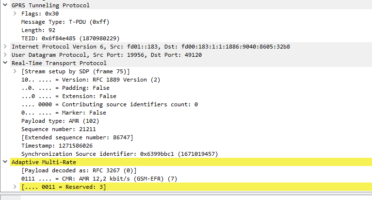
Payload Type (7 bits)

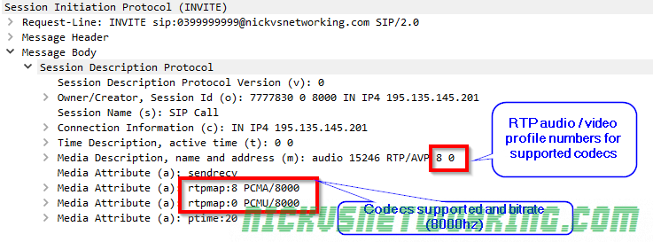
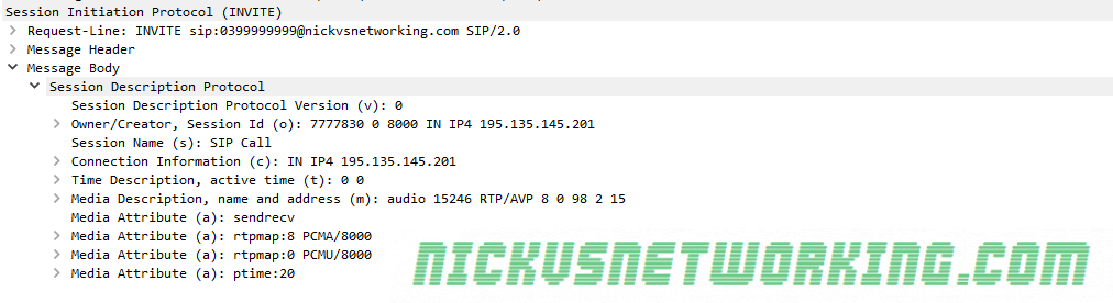
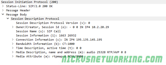
The payload type is what specifies the contents of the payload. In voice terms this means the codec we’re using. RFC3551 defines some predefined payload type definitions and it’s Payload Type code.

Your values might not appear in the RFC3551 definitions if you’re using a non-standard codec, and that’s Ok. RTP could be used to play video games or pilot an RC plane, it’s really just a protocol to carry a stream of real time data quickly from point A to point B with as little overhead as possible.

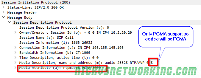
PCMA / PCMU is king here thanks to it G.711’s widespread adoption due to being the codec used in TDM, and the fact you don’t need to transcode PCM to bring the traffic into the network, or compress it from a TDM source. TDM / circuit switched services are way less common on the network edge these days,  but G.711 still holds on as the defacto standard.

So for a G711 a-law (PCMA) payload this value would be 8, which is 0001000 in Binary (it’s also equivalent to 1000 in binary but we need to fill all 7 bits because we’re using fixed-width formatting, so we prefix it with zeros, if we were using GSM, which is 8 in decimal and 11 in binary, we’d format is 0000011)

For the full list of Payload types check out IANA’s Real-Time Transport Protocol (RTP) Parameters.

Sequence Number (16 bits)

The sequence number is a supposedly random number that increments by 1 for each packet sent.
This allows the receiving party to calculate packet loss, because if you receive packets with the sequence number 1,2,3,5,6 you know you’ve missed packet 4.
It also allows us to calculate our packet delay variation (PDV), and helps our jitterbuffer re-assemble packets, if we receive packets 1,3,2,4,5,6 we can see they’re out of sequence and know to play them back in the order 1,2,3,4,5,6, not the order we received them.

The sequence numbers are supposed to be random. By having this as a random number it adds an extra unknown part of the packet for someone trying to break any crypto on top to guess. Polycom however just start all theirs at 0. (Slow clap)

This is a 16 bit number, so like the payload type we’ll have to convert it from decimal to binary, then pad it to be 16 bits. So if our starting sequence number is 1234 we’d have to convert it to binary (10011010010) and then pad it to 16 characters (0000010011010010)

Timestamp (32 bits)

The timestamp, like the sequence number is supposed to begin with a random number, and then increased by the sampling instances between packets “monotonically and linearly in time”. In essence it means a random starting number + time between packets.

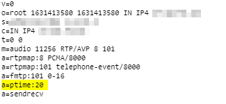
The value increments by the packetization time (ptime) in seconds x bandwidth in Hz.
So for a call with a ptime of 20ms at 8Khz this would be:

0.020 x 8000 = 160, so increment by 160 each packet.

Having an accurate source for the timestamp allows accurate stats to be generated for PDV, jitter etc, without this value being accurate your RTCP values will always appear off, even if the audio is fine.

If we wanted a timestamp of 837026880, we’d need to convert it to Binary (110001111001000000010001000000) and pad it to ensure it’s 32 bits long (this value already is so no need to pad).

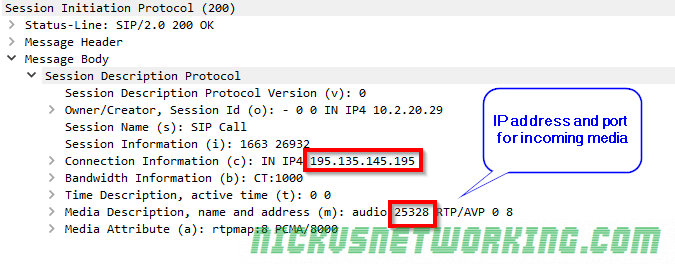
SSRC (Synchronization Source Identifier) (32 bits)

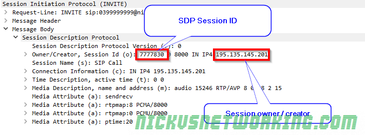
The SSRC is like a Call-ID, a unique value that identifies one RTP stream from another. If you had two packets to the same port, from the same IP, with roughly the same sequence number & timestamp you’d need a way to determine which RTP stream is for which session. This is where the SSRC comes in, a unique identifier that identifies one RTP stream from the others.

To keep it random the spec’ even suggests ways to generate a random value based on other values.

If we wanted to use 185755418 as or SSRC we’d need to convert it to Binary (1011000100100110011100011010) and pad it to 32 bits (00001011000100100110011100011010)

CSRC List (Contributing source list) (0 to 15 individual 32 bit values)

This contains a list of the contributing sources. Depending on how many sources were specified in your CSRC Count, this can have any number of items from 0 to 15. So if you had one contributing source in the CSRC Count, then you’d have 1x 32 bit value to specify the details of the SSRC identifiers of the sources.

This will always not exist if the CSRC Count is 0.

Payload

The payload is whatever you want it to be, so long as you specify it in the Payload Type field, and pad it if enabled, any data can be put here.


Further Reading

I got a copy of the Colin Perkin’s book RTP: Audio and Video for the Internet, which covers everything you need to ever know about RTP. I’d highly recommend it. It was written in 2003, is still just as relevant as more and more traffic moves off circuit switched into packet switched.

SDP – Session Description Protocol – Overview

Content-Type application/sdp is something you’ll see a whole lot when using SIP for Voice over IP, especially in INVITEs and 200 OK responses.

This is because SIP uses SDP to negotiate the media setup.

While Voice over IP uses RTP for media, and SIP for signalling, the meat in this sandwich is SDP, used to negotiate the RTP parameters and payloads before going ahead.

Without SDP you’d just have random unidentified RTP streams going everywhere and no easy way to correlate them back to a Session (SIP) or guarantee both endpoints support the same codec (RTP payload).

Enter SDP, the Session Description Protocol, before any RTP is sent, SDP advertises capabilities (which codecs to use), contact information, port information (which port to send the RTP stream to) and attempts to negotiate a media session both endpoints can support.

SDP is designed to be lightweight, while SIP uses human readable headers like To and From, SDP does away with this in favour of single letters representing what that header contains.

As an interesting aside, SIP at one stage also offered one-letter headers to make it smaller on the wire, but this never really took off.

Here we can see what an SDP header looks like, showing the Session ID, Session Name, Connection Information and Media Descriptions.

SDP from an INVITE

Let’s dig a little deeper and have a look at what this SDP header actually shows that’s useful to us.

The SDP Offer

Session Identifiers

Session information

The Owner / Creator & Session ID header (abbreviated to o=) contains the SDP session ID and the session owner / creator information. This contains the SDP Session ID and the IP Address / FQDN of the owner or creator of this session. In this case the SDP Session ID is 777830 and the Session owner / creator is 195.135.145.201.

Connection Information

Receiving / listening information

Next up we’ve got the connection information header (abbreviated to c=) which contains the IP Address we want the incoming RTP stream sent to. In this example it’s coming IN on IPv4 address 192.135.154.201.

The Media Description header (m=) also contains the port we want to receive the audio on, 15246.

So in summary we’re telling the called party that we’ll be listening on IP Address 192.135.154.201 on port 15246, so they should send their RTP audio stream to that address & port.

Media Attributes

Media attributes

The Media Description header (abbreviated to m=) contains a name and address, in this case it’s audio, and sent to address (port) 15246.

After that we’ve got the RTP Audio / Video profile numbers. Because SDP is designed to be lightweight instead of saying PCMA, PCMU here each codec is assigned a number by IANA that translates to a codec. The full list is here, but 8 is equal to PCMA and 0 is equal to PCMU.

So from the Media Description header we can learn that it’s an Audio session, with media to be sent to port 15246, via RTP using PCMA or PCMU.

Different codecs can have different bitrates, so by using the Media Attribute header (Abbreviated to a=) we can set the bitrates for each. In this case both PCMA and PCMU are using a bitrate of 8000.

Summary

So to summarise we’ve told the party we’re calling our session ID is 777830 and it’s owned / created by 195.135.145.201. We support PCMA and PCMU at 8000Hz, and we’ll be listening on IPv4 on 195.135.145.201 on port 15246 for them to send their audio stream to.

The SDP Answer

Next we’ll take a look at the SDP from a 200 OK response, and work out what our session will look like.

Codec Selection

We can see this device only supports PCMA, which makes codec selection pretty easy, it’s going to be PCMA as that was also supported in the SDP offer contained in the initial INVITE.

In the scenario where both devices support the same codecs, the order in which the codecs are listed defines what codec is selected.

Connection Information

Like in the SDP offer we can see that we’re requesting incoming RTP / media to be sent to, in this case we’re asking for the RTP / media on 195.135.145.195 port 25328

Final Steps

Generally after the 200 OK is received an ACK is sent and media starts flowing in both directions between endpoints.

In this example 195.135.145.195 will send their audio (aka media / RTP) to 195.135.145.201 on port 15246 (called party to the caller) and 195.135.145.201 will send their audio to 195.135.145.195 on port 25328 (calling party to the called party).

It’s always worth keeping in mind that SIP doesn’t have to be used for Voice, nor does it have to use SDP, nor does SDP have to be used with SIP, it can be used with other protocols (IAX, H.323), and doesn’t have to negotiate RTP sessions, but could negotiate anything.

That said, the SIP – SDP – RTP sandwich is pretty ubiquitous for good reason, and while it’s true that none of these protocols require each other, the truth is, most of their usage is with one-another and it’s easier to just say “SIP uses SDP” and “SDP uses RTP” than continually saying “SIP can use SDP” and “SDP can use RTP” etc.

DTMF over IP – SIP INFO, Inband & RTP Events

DTMF (Dual Tone Modulated Frequency) aka touch tone, was initially designed to be a faster method of dialling since make-and-break dial pulses were slow and a more efficient method for user input was required switching was becoming digital.

By using two tones DTMF tones, switching equipment could be easily identify the input without complex circuitry, and because it uses two tones the chances of someone accidentally generating the two-tone pair was slim. MF had been used for tandem / trunk signalling inside the network with great success, so DTMF was a standout choice.

SIP was never explicitly designed as a telephony protocol, and as such, it’s support for DTMF wasn’t baked in from the start.

Over time organisations started using DTMF so users could interact with IVRs, Auto Attendants, enter PIN codes and interact with services using their telephone, ideas that wen’t beyond the call setup function originally imagined for DTMF.

Your standard subscriber loop POTS line doesn’t have any out of band signalling for the DTMF, but the carrier switch passes through the audio end to end, and the DTMF tones are carried in that audio, so it’s not a problem.

So when SIP rolled along as the defacto standard for Voice calls over IP, it didn’t have a method for signalling that a DTMF digit had been placed.

Never to fear, neither does a POTS line, so everything will be fine and the tones will just be carried in the media stream like they do on a POTS line.

This was called in-band DTMF. In-band because the DTMF tones are carried in the audio stream like they would if you were to playback those tones on a tape recorder or harmonised whistling.

However along came G.729 and other compressed codecs and suddenly these two tones were lost in compression, so the VoIP world needed a new way to transport DTMF information.

RFC2833 came to fix this problem in 2000, introducing a special RTP packet called an “RTP Event” that denoted a DTMF key-press, which evolved into RFC4733, carrying the DTMF as an RTP event.

Here’s a post I did on RFC2833 DTMF.

For some reason this method of DTMF signalling is still referred to as RFC2833, despite the fact that most implementations are of RFC4733.

But the next problem facing SIP implementers was SIP Proxies had no awareness of the DTMF events, because by definition, a SIP proxy only works with the SIP (signalling) part of the call, not the RTP (media).

So for a device to know when a DTMF keypress happened it’d have to be listening in to the RTP media stream to pickup the RTP events.

The solution that’s considered best practices today actually predates the other two standards. RFC2976 describes using SIP INFO messages to carry payloads. (Link to post on the topic)

In the case of using SIP INFO for payloads, the DTMF info is put into this payload, so this is often used now to carry DTMF info as well as ISUP messaging.

Seems like backwards step, but Proxies can be aware of DTMF messaging and interoperability is in theory enhanced.

The disadvantage is there’s now 3 possible implimentations, DTMF Inband, DTMF in RTP Events, and DTMF in SIP INFO.

Some endpoints use more than one method, some even use all 3. The idea being that it’ll “just work” and won’t need configuring. So when a user presses a digit it plays the tone (in-band), sends an RTP event (RFC4733/2833) and sends a SIP INFO message containing the pressed digit (RFC2976) all at once.

This can cause huge headaches if the switch it’s talking to can recognise more than one type of DTMF signalling it gets multiple inputs, causing jumping through IVRs and menus.

If only we had one universal standard…

See also:

RFC2976 / RFC6086 – SIP INFO

RFC2833 – RTP Events

RTP – More than you wanted to Know

RFC2833 – RTP Events

RFC2833 was designed to carry DTMF signalling, other tone signals and telephony events in RTP packets.

This was later superseded by RFC4733, but everyone still referrers to this protocol as RFC2833, so I will too.

RFC2833 a special RTP payload designed to carry DTMF signalling information, so it operates on the same source / destination ports as the RTP signal and you’ll see it mixed in there when viewing packet captures.

It uses RTP’s Synchronisation Source Identifiers to identify the stream, and uses the next RTP sequence numbers, so it relies on RTP to sort pretty much everything.

The RTP Event itself, contains an Event ID header (called “event” in the spec), End of Event flag, Reserved flag, Volume header and Event Duration header.

Event ID (event)

The Event header contains the event that is being conveyed. For DTMF this would be the numeral 8 (8) for DTMF Eight.

DTMF named events

End of Event

The End of Event (Referred to as E in the RFC) flag is set to 1 if the transmitted packet is the end of an RTP event.

This allows for a key press to span over multiple packets, with the end of the key-press (key release) denoted by this flag.

Reserved Flag

The reserved flag (R) is reserved for future use, and will just be set to 0.

Volume

This is only used for DTMF digits and denotes the volume of the tone in dB from 0 to -36 dBm0.

Event Duration

The event duration tag. When a DTMF keypress is split over multiple RTP Event packets, the first will start at 0 and then this will count up by the time incremented in the timestamp.

Analysing in Wireshark

By using the display filter “rtpevent” you can see all the RTP events for you call.

Each DTMF event will contain multiple packets, with the total number depending on how long the keypress is and packetization timers.

When they key is pressed by the user, an RTP event with a duration of 0 and the Event ID of the DTMF digit is sent.

For as long as the digit is held, subsequent packets with a totalled event duration will keep being sent,

Finally when the key is released an RTP Event with the “End of Event” header set to True will be sent to mark the end of the RTP Event.

See also:

DTMF over IP – SIP INFO, Inband & RTP Events

RFC2976 / RFC6086 – SIP INFO