In the cellular world, subscribers are charged for data from the IP, transport and applications layers; this means you pay for the IP header, you pay for the TCP/UDP header, and you pay for the contents (the cat videos it contains).
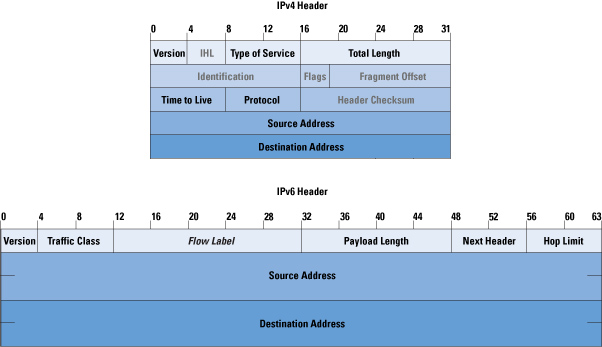
This also means if an operator moves mobile subscribers from IPv4 to IPv6, there’s an extra 20 bytes the customer is charged for for every packet sent / received, which the customer is charged for – This is because the IPv6 header is longer than the IPv4 header.
In most cases, mobile subs don’t get a choice as to if their connection is IPv4 or IPv6, but on a like for like basis, we can say that if a customer moves is on IPv6 every packet sent/received will have an extra 20 bytes of data consumed compared to IPv4.
This means subscribers use more data on IPv6, and this means they get charged for more data on IPv6.
For IoT applications, light users and PAYG users, this extra 20 bytes per packet could add up to something significant – But how much?
We can quantify this, but we’d need to know the number of packets sent on average, and the quantity of the data transferred, because the number of packets is the multiplier here.
So for starters I’ve left a phone on the desk, it’s registered to the network but just sitting in Idle mode – This is an engineering phone from an OEM, it’s just used for testing so doesn’t have anything loaded onto it in terms of apps, it’s not signed into any applications, or checking in the background, so I thought I’d try something more realistic.
So to get a clearer picture, I chucked a SIM in my regular everyday phone I use personally, registered it to the cellular lab I have here. For the next hour I sniffed the GTP traffic for the phone while it was sitting on my desk, not touching the phone, and here’s what I’ve got:
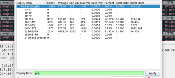
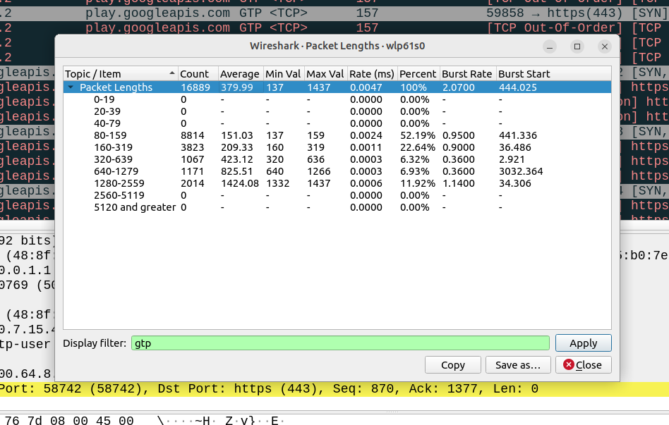
Overall the PCAP includes 6,417,732 bytes of data, but this includes the transport and GTP headers, meaning we can drop everything above it in our traffic calculations.
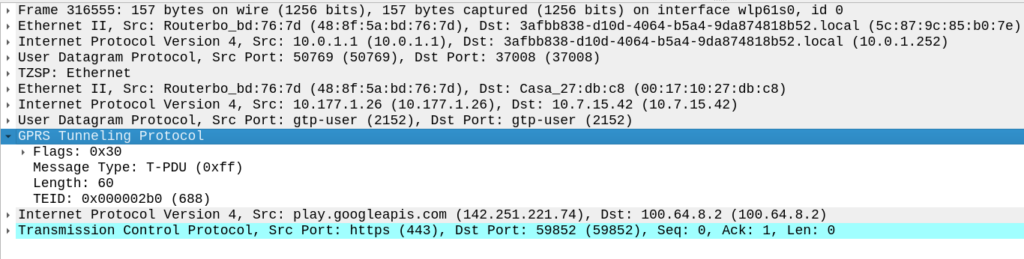
For this I’ve got 14 bytes of ethernet, 20 bytes IP, 8 bytes UDP and 5 bytes for TZSP (this is to copy the traffic from the eNB to my local machine), then we’ve got the transport from the eNB to the SGW, 14 bytes of ethernet again, 20 bytes of IP , 8 bytes of UDP and 8 bytes of GTP then the payload itself. Phew. All this means we can drop 97 bytes off every packet.
We have 16,889 packets, 6,417,732 bytes in total, minus 97 bytes from each gives us 1,638,233 of headers to drop (~1.6MB) giving us a total of 4.556 MB traffic to/from the phone itself.
This means my Android phone consumes 4.5 MB of cellular data in an hour while sitting on the desk, with 16,889 packets in/out.
Okay, now we’re getting somewhere!
So now we can answer the question, if each of these 16k packets was IPv6, rather than IPv4, we’d be adding another 20 bytes to each of them, 20 bytes x 16,889 packets gives 337,780 bytes (~0.3MB) to add to the total.
If this traffic was transferred via IPv6, rather than IPv4, we’d be looking at adding 20 bytes to each of the 16,889 packets, which would equate to 0.3MB extra, or about 7% overhead compared to IPv4.
But before you go on about what an outrage this IPv6 transport is, being charged for those extra bytes, that’s only one part of the picture.
There’s a reason operators are finally embracing IPv6, and it’s not to put an extra 7% of traffic on the network (I think if you asked most capacity planners, they’d say they want data savings, not growth).
IPv6 is, for lack of a better term, less rubbish than IPv4.
There’s a lot of drivers for IPv6, and some of these will reduce data consumption. IPv6 is actually your stuff talking directly to the remote stuff, this means that we don’t need to rely on NAT, so no need to do NAT keepalives, and opening new sessions, which is going to save you data. If you’re running apps that need to keep a connection to somewhere alive, these data savings could negate your IPv6 overhead costs.
Will these potential data savings when using IPv6 outweigh the costs?
That’s going to depend on your use case.
If you’ve extremely bandwidth / data constrained, for example, you have an IoT device on an NTN / satellite connection, that was having to Push data every X hours via IPv4 because you couldn’t pull data from it as it had no public IP, then moving it to IPv6 so you can pull the data on the public IP, on demand, will save you data. That’s a win with IPv6.
If you’re a mobile user, watching YouTube, getting push notifications and using your phone like a normal human, probably not, but if you’re using data like a normal user, you’ve probably got a sizable data allowance that you don’t end up fully consuming, and the extra 20 bytes per packet will be nothing in comparison to the data used to watch a 2k video on your small phone screen.
Ask someone with headphones and a lanyard in the halls of a datacenter what transport does DNS use, there’s a good chance the answer you’d get back is UDP Port 53.
But not always!
In scenarios where the DNS response is large (beyond 512 bytes) a DNS query will shift over to TCP for delivery.
How does the client know when to shift the request to TCP – After all, the DNS server knows how big the response is, but the client doesn’t.
The answer is the Truncated flag, in the response.
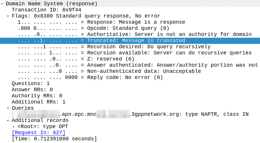
The DNS server sends back a response, but with the Truncated bit set, as per RFC 1035:
TC TrunCation – specifies that this message was truncated due to length greater than that permitted on the transmission channel.
RFC 1035
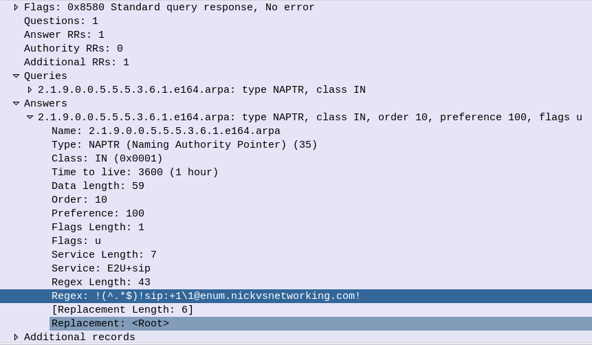
Here’s an example of the truncated bit being set in the DNS response.
The DNS client, upon receiving a response with the truncated bit set, should run the query again, this time using TCP for the transport.
One prime example of this is DNS NAPTR records used for DNS in roaming scenarios, where the response can quite often be quite large.
If it didn’t move these responses to TCP, you’d run the risk of MTU mismatches dropping DNS. In that half of my life has been spent debugging DNS issues, and the other half of my life debugging MTU issues, if I had MTU and DNS issues together, I’d be looking for a career change…
I had a question recently on LinkedIn regarding how to preference Voice over WiFi traffic so that a network engineer operating the WiFi network can ensure the best quality of experience for Voice over WiFi.
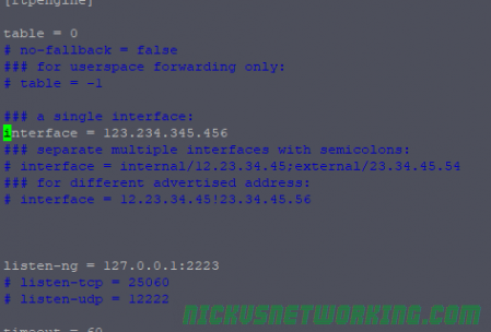
Voice over WiFi is underpinned by the ePDG – Evolved Packet Data Gateway (this is a fancy IPsec tunnel we authenticate to using the SIM to drop our traffic into the P-CSCF over an unsecured connection). To someone operating a WiFi network, the question is how do we prioritise the traffic to the ePDGs and profile it?
ePDGs can be easily discovered through a simple DNS lookup, once you know the Mobile Network Code and Mobile Country code of the operators you want to prioritise, you can find the IPs really easily.
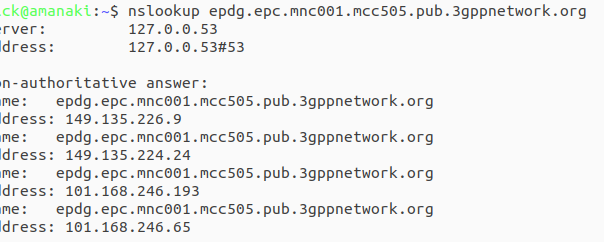
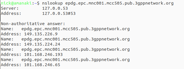
ePDG addresses take the form epdg.epc.mncXXX.mccYYY.pub.3gppnetwork.org so let’s look at finding the IPs for each of these for the operators in a country:
The first step is nailing down the mobile network code and mobile country codes of the operators you want to target, Wikipedia is a great source for this information. Here in Australia we have the Mobile Country Code 505 and the big 3 operators all support Voice over WiFi, so let’s look at how we’d find the IPs for each. Telstra has mobile network code (MNC) 01, in 3GPP DNS we always pad network codes to 3 digits, so that’ll be 001, and the mobile country code (MCC) for Australia is 505. So to find the IPs for Telstra we’d run an nslookup for epdg.epc.mnc001.mcc505.pub.3gppnetwork.org – The list of IPs that are returned, are the IPs you’ll see Voice over WiFi traffic going to, and the IPs you should provide higher priority to:
The same rules apply in other countries, you’d just need to update the MNC/MCC to match the operators in your country, do an nslookup and prioritise those IPs.
Generally these IPs are pretty static, but there will need to be a certain level of maintenance required to keep this list up to date by rechecking.
There’s old joke about standards that the great thing about standards there’s so many to choose from.
SMS wasn’t there from the start of GSM, but within a year of the inception of 2G we had SMS, and we’ve had SMS, almost totally unchanged, ever since.
In a recent Twitter exchange, I was asked, what’s the best way to transport SMS? As always the answer is “it depends” so let’s take a look together at where we’ve come from, where we are now, and how we should move forward.
How we got Here
Between 2G and 3G SMS didn’t change at all, but the introduction of 4G (LTE) caused a bit of a rethink regarding SMS transport.
Early builders of LTE (4G) networks launched their 4G offerings without 4G Voice support (VoLTE), with the idea that networks would “fall back” to using 2G/3G for voice calls.
This meant users got fast data, but to make or receive a call they relied on falling back to the circuit switched (2G/3G) network – Hence the name Circuit Switched Fallback.
Falling back to the 2G/3G network for a call was one thing, but some smart minds realised that if a phone had to fall back to a 2G/3G network every time a subscriber sent a text (not just calls) – And keep in mind this was ~2010 when SMS traffic was crazy high; then that would put a huge amount of strain on the 2G/3G layers as subs constantly flip-flopped between them.
The SGs-AP interface has two purposes; One, It can tell a phone on 4G to fallback to 2G/3G when it’s got an incoming call, and two; it can send and receive SMS.
SMS traffic over this interface is sometimes described as SMS-over-NAS, as it’s transported over a signaling channel to the UE.
This also worked when roaming, as the MSC from the 2G/3G network was still used, so SMS delivery worked the same when roaming as if you were in the home 2G/3G network.
Enter VoLTE & IMS
Of course when VoLTE entered the scene, it also came with it’s own option for delivering SMS to users, using IP, rather than the NAS signaling. This removed the reliance on a link to a 2G/3G core (MSC) to make calls and send texts.
This was great because it allowed operators to build networks without any 2G/3G network elements and build a fully standalone LTE only network, like Jio, Rakuten, etc.
In roaming scenarios, S8 Home Routing for VoLTE enabled SMS to be handled when roaming the same way as voice calls, which made SMS roaming a doddle.
4G SMS: SMS over IP vs SMS over NAS
So if you’re operating a 4G network, should you deliver your SMS traffic using SMS-over-IP or SMS-over-NAS?
Generally, if you’ve been evolving your network over the years, you’ve got an MSC and a 2G/3G network, you still may do CSFB so you’ve probably ended up using SMS over NAS using the SGs-AP interface. This method still relies on “the old ways” to work, which is fine until a discussion starts around sunsetting the 2G/3G networks, when you’d need to move calling to VoLTE, and SMS over NAS is a bit of a mess when it comes to roaming.
Greenfield operators generally opt for SMS over IP from the start, but this has its own limitations; SMS over IP is has awful efficiency which makes it unsuitable for use with NB-IoT applications which are bandwidth constrained, support for SMS over IP is generally limited to more expensive chipsets, so the bargain basement chips used for IoT often don’t support SMS over IP either, and integration of VoLTE comes with its own set of challenges regarding VoLTE enablement.
5G enters the scene (Nsmsf_SMService)
5G rolled onto the scene with the opportunity to remove the SMS over NAS option, and rely purely on SMS over IP (IMS); forcing the industry to standardise on an option alas this did not happen.
This added another option for SMS delivery dependent on the access network used, and the Nsmsf_SMService interface does not support roaming.
Of course if you are using Voice over NR (VoNR) then like VoLTE, SMS is carried in a SIP message to the IMS, so this negates the need for the Nsmsf_SMService.
2G/3G Shutdown – Diameter to replace SGs-AP (SGd)
With the 2G/3G shutdown in the US operators who had up until this point been relying on SMS-over-NAS using the SGs-AP interface back to their MSCs were forced to make a decision on how to route SMS traffic, after the MSCs were shut down.
This landed with SMS-over-Diameter, where the 4G core (MME) communicates over Diameter with the SMSc.
This has adoption by all the US operators, but we’re not seeing it so widely deployed in the rest of the world.
State of Play
Option
Conditions
Notes
MAP
2G/3G Only
Relies on SS7 signaling and is very old Supports roaming
SGs-AP (SMS-over-NAS)
4G only relies on 2G/3G
Needs an MSC to be present in the network (generally because you have a 2G/3G network and have not deployed VoLTE) Supports limited roaming
SMS over IP (IMS)
4G / 5G
Not supported on 2G/3G networks Relies on a IMS enabled handset and network Supports roaming in all S8 Home Routed scenarios Device support limited, especially for IoT devices
Diameter SGd
4G only / 5G NSA
Only works on 4G or 5G NSA Better device support than 4G/5G Supports roaming in some scenarios
Nsmsf_SMService
5G standalone only
Only works on 5GC Doesn’t support roaming
The convoluted world of SMS delivery options
A Way Forward:
While the SMS payload hasn’t changed in the past 31 years, how it is transported has opened up a lot of potential options for operators to use, with no clear winner, while SMS revenues and traffic volumes have continued to fall.
For better or worse, the industry needs to accept that SMS over NAS is an option to use when there is no IMS, and that in order to decommission 2G/3G networks, IMS needs to be embraced, and so SMS over IP (IMS) supported in all future networks, seems like the simple logical answer to move forward.
And with that clear path forward, we add in another wildcard…
But, when you’ve only got a finite resource of bandwidth, and massive latencies to contend with, the all-IP architecture of IMS (VoLTE / VoNR) and it’s woeful inefficiency starts to really sting.
Of course there are potential workarounds here, Robust Header Correction (ROHC) can shrink this down, but it’s still going to rely on the 3 way handshake of TCP, TCP keepalive timers and IMS registrations, which in turn can starve the radio resources of the satellite link.
Even with SMS over 30 years old, we can still expect it to be a part of networks for years to come, even as WhatsApp / iMessage, etc, offer enhanced services. As to how it’s transported and the myriad of options here, I’m expecting that we’ll keep seeing a multi-transport mix long into the future.
For simple, cut-and-dried 4G/5G only network, IMS and SMS over IP makes the most sense, but for anything outside of that, you’ve got a toolbox of options for use to make a solution that best meets your needs.
I needed to have both legs of the B2BUA bridge call through FreeSWITCH using the same Call-ID (long story), and went down the rabbit hole of looking for how to do this.
A post from 15 years ago on the mailing list from Anthony Minessale said he added “sip_outgoing_call_id” variable for this, and I found the commit, but it doesn’t work – More digging shows this variable disappears somewhere in history.
But by looking at what it changed I found sip_invite_call_id does the same thing now, so if you want to make both legs use the same Call-ID here ya go:
Even before 5G was released, the arms race to claim the “fastest” speeds on LTE, NSA and SA networks has continued, with pretty much every operator claiming a “first” or “fastest”.
I myself have the fastest 5G network available* but I thought I’d look at how big the values are we can put in for speed, these are the Maximum Bitrate Values (like AMBR) we can set on an APN/DNN, or on a Charging Rule.
*Measurement is of the fastest 5G network in an eastward facing office, operated by a person named Nick, in a town in Australia. Other networks operated by people other than those named Nick in eastward facing office outside of Australia were not compared.
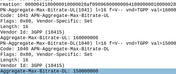
The answer for Release 8 LTE is 4294967294 bytes per second, aka 4295 Mbps 4.295 Gbps.
Not bad, but why this number?
The Max-Requested-Bandwidth-DL AVP tells the PGW the max throughput allowed in bits per second. It’s a Unsigned32 so max value is 4294967294, hence the value.
But come release 15 some bright spark thought we may in the not to distant future break this barrier, so how do we go above this?
The answer was to bolt on another AVP – the “Extended-Max-Requested-BW-DL” AVP ( 554 ) was introduced, you might think that means the max speed now becomes 2x 4.295 Gbps but that’s not quite right – The units was shifted.
This AVP isn’t measuring bits per second it’s measuring kilobits per second.
So the standard Max-Requested-Bandwidth-DL AVP gives us 4.3 Gbps, while the Extended-Max-Requested-Bandwidth gives us a 4,295 Gbps.
We add the Extended-Max-Requested-Bandwidth AVP (4295 Gbps) onto the Max-Requested Bandwidth AVP (4.3 Gbps) giving us a total of 4,4299.3 Gbps.
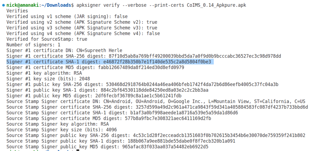
I started off just updating the SPN, OPN, etc, etc, but I had a suspicion there were still references.
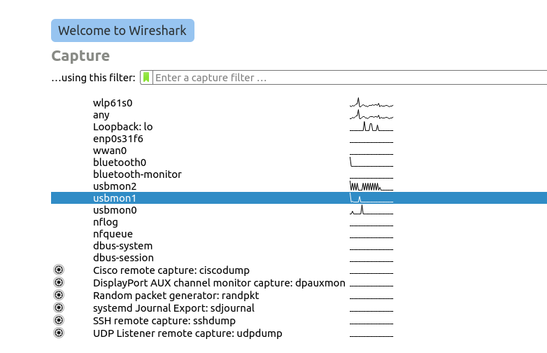
I confirmed this pretty easily with Wireshark, first I started a trace in Wireshark of the APDUs: I enabled capturing on a USB Interface:
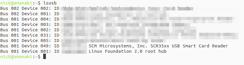
modprobe usbmon
Then we need to find where our card reader is connected, running ‘lsusb‘ lists all the USB devices, and you can see here’s mine on Bus 1, Device 49.
Then fired up Wireshark, selected USB Bus 01 to capture all the USB traffic on the bus.
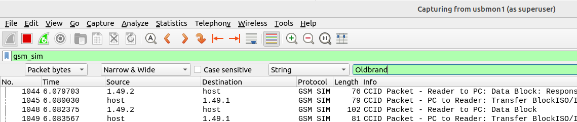
Then I ran the “export” command in PySIM to read the contents of all the files on the SIM, and jumped back over to Wireshark. (PySIM decodes most files but not all – Whereas this method just looks for the bytes containing the string)
From the search menu in Wireshark I searched the packet bytes for the string containing the old brand name, and found two more EFs I’d missed.
For anyone playing along at home, using this method I found references to the old brand name in SMSP (which contains the network name) and ADN (Which had the customer support number as a contact with the old brand name).
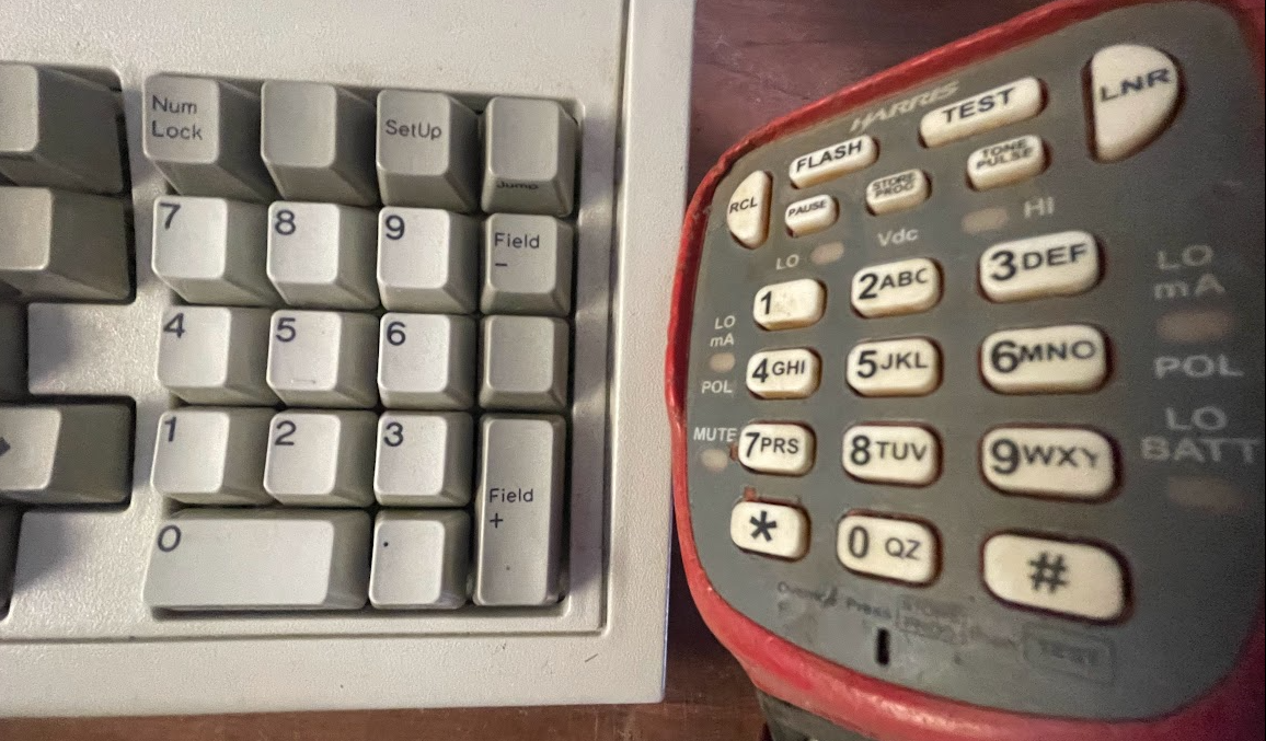
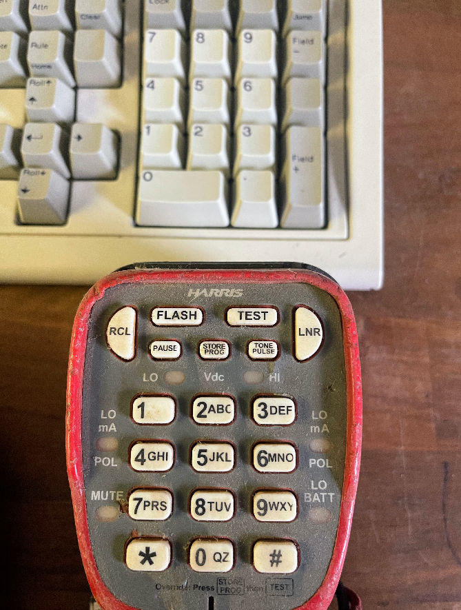
If you’re typing on a full size keyboard there’s a good chance that to your right, there’s a number pad.
The number 5 is in the middle – That’s to be expected, but is 1 in the top left or bottom left?
Being derived from an adding machine keypad, the number pad on a keyboard has a 1 will be in the bottom left, however in the 1950s when telephone keypads were being introduced, only folks who worked in accounting had adding machines.
So when it came time to work out the best layout, the result we have today was a determined through a stack of research and testing by Human Factors Engineering Department of Bell Labs who studied the most efficient layout of keys, and tested focus groups to find the layout that provided the best level of speed and accuracy.
That landed with the 1 in the top left, and that’s what we still have today.
Oddly ATM and Card terminals opted to use the telephone layout, rather than the adding machine layout, while number pads use the adding machine layout.
Note: All information contained here is sourced from: Photos provided by NBNco’s press pages, Googling part numbers from these photos, and public costing information.
This post covers the specifics and capabilities of NBNco’s FTTN solution, and is the result of some internet sleuthing.
If some of the info in here is now out of date, I’d love to know, let me know in the comments or drop me an email and I’ll update it.
FTTN in Numbers
A total of 24,544 nodes have been deployed upon completion of roll out. Each node is provisioned with 384 subscriber ports.
The hardware has 10Gbps shared between the 384 subscriber lines, equating to 208Mbps per subscriber.
Construction costs were $2.311 billion and hardware costs were $1.513 billion,
For the hardware this equates to $61,644 per node or $160 per subscriber line connected (each node is provisioned with 384 ports)
Full cost for node including hardware, construction and provisioning is $244,150 per node, which is $635 per port.
To operate the FTTN infrastructure costs $709 million per year (Made up of costs such as power, equipment servicing and spares). This equates to $28k per node per annum, or $75 per subscriber. (This does not take into account other costs such as access to the copper, transmission network, etc, just the costs to have the unit powered on the footpath.)
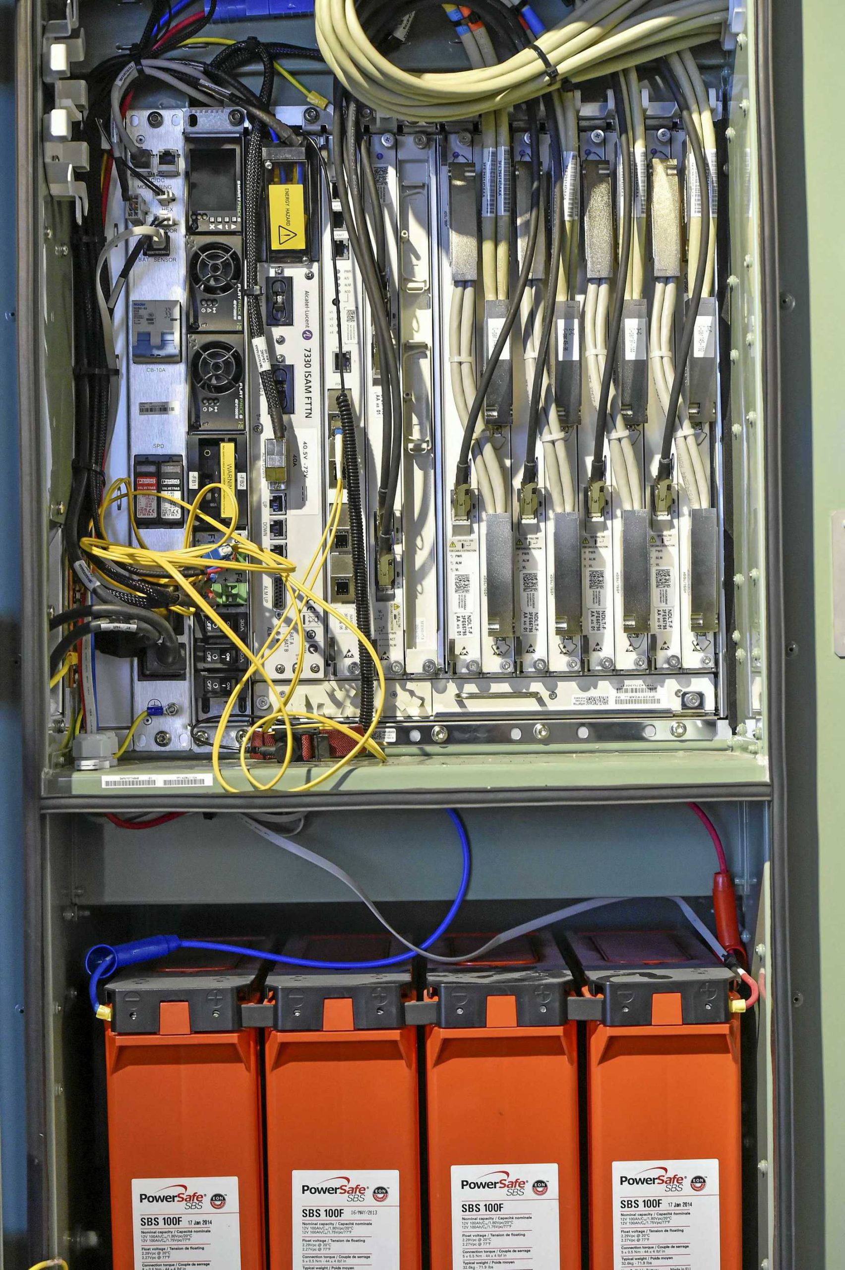
Overview
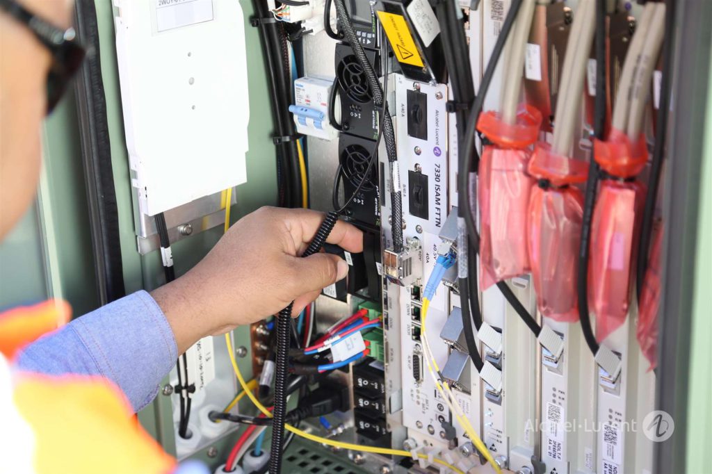
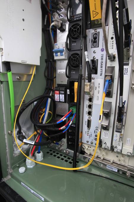
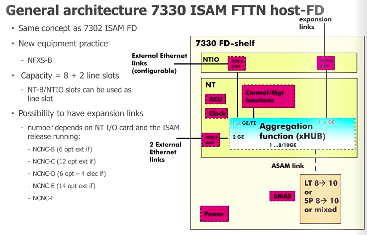
Inside the FTTN cabinets is a Alcatel Lucent (now Nokia) ISAM 7330 cabinet mounted on it’s side,
On the inside left of the door is a optic fibre tray where the transmission links come into the cabinet,
On the extreme left is a custom panel. It contains I/Os that are fed to the 7330, such as door open sensor, battery monitoring, AC power in, SPD and breaker.
Connection to subscriber lines happens on a frame at the end of the cabinet.
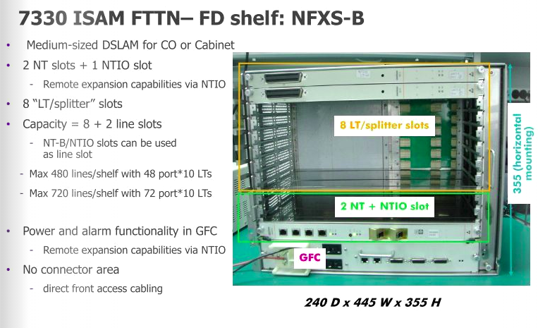
Alcatel Lucent ISAM 7330 FTTN
NBN co’s nodes are made up of Alcatel Lucent (Now Nokia) ISAM (Intelligent Services Access Manager) 7330 FTTN rack mounted it’s side.
Slot
Type
Function
1
GFC (General Facilities Card)
Power and alarm management
2
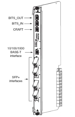
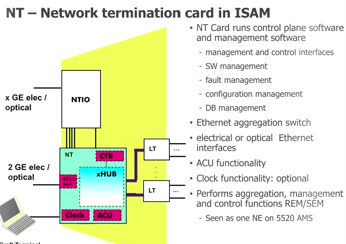
NT Slot (NANT-E Card)
Main processing and transmission
3
NTIO Slot (NDPS-C Card)
VDSL vectoring number-crunching
4
NT Slot (Free)
Optional (Unused) backup Main processing and transmission
5-12
LT (NDLT-F)
48 Port VDSL Subscriber DSLAM Interfaces
Slot numbering is just counting L to R, ALU documentation has different numbering
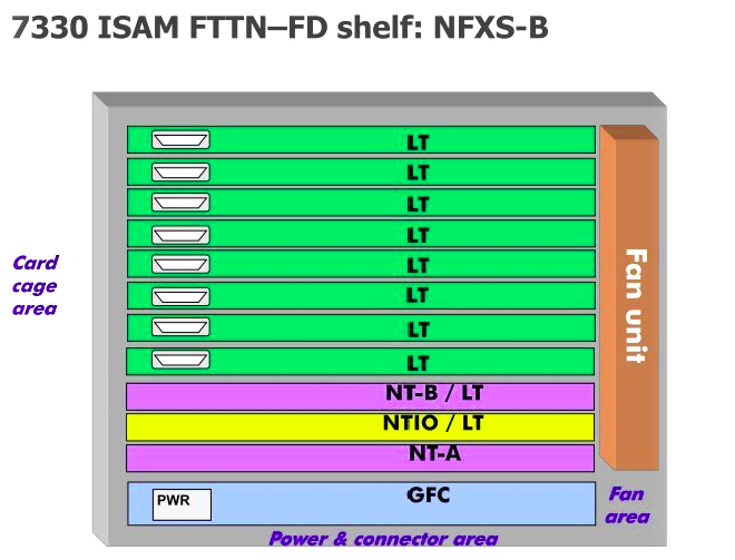
First up is the GFC (General Facilities Card) which handles alarm input / output, and power distribution. This connects to the custom IO panel on the far left of the cabinet, meaning the on-board IO ports aren’t all populated as it’s handled by the IO panel. (More on that later)
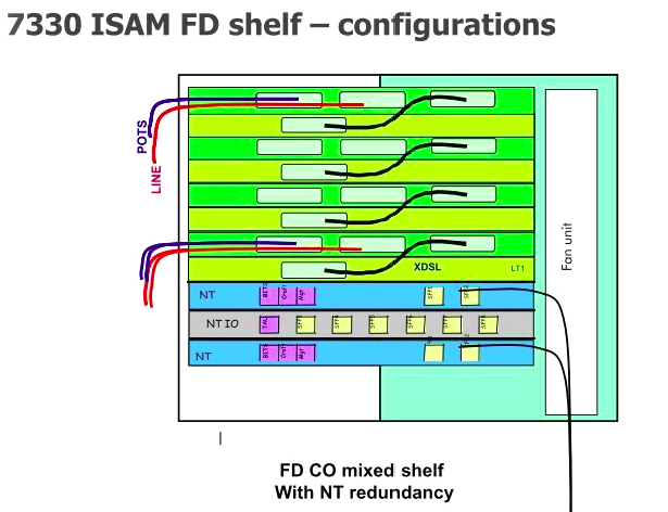
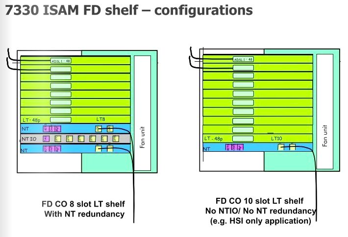
Next up is the first NT slot, there are two on the 7330, but in NBN’s case, only one is used; the second can be used for redundancy if one of the cards were to fail, but it seems this option has not been selected. In the first and only populated NT slot is an NANT-E Card (Combined NT Unit E) which handles transmission and main processing.
All the ISAM NANT cards support support RIPv2! But only the NANT-E card also supports BGP – Interestingly they don’t have BGP on all the NANT cards?
To the right of that is the NTIO slot, which has a NDPS-C card, which handles the vector processing for VDSL.
Brief overview of Vectoring: By adding vectoring to DSL signals allows noise on subscriber loops to be modeled, and then cancelled out with an integrated anti-phase signal matching that of the noise.
The vectoring in VDSL relies on pretty complex number crunching as the DSLAM has to constantly process the vectoring coefficients which are different for each line and can change based on the conditions of the subscriber loop etc. To do this the NDPS-C has two roles; The NDPS-C’s Vectoring Control Entity performs non-real time calculations of vectoring coefficients and handles joining and leaving of vectored VDSL2 lines. While the NDPS-C’s Vectoring Processor performs the real time matrix calculations based on crosstalk correction samples for the VDSL symbols collected from the subscriber lines. The NDPS-C has a Twinax connection to every second LT Card.
After the NTIO slot is the unused NT slot.
Finally we have the 8 LT slots for line cards, which for FTTN is using the NDLT-F are 48 port line cards.
The 8 card slots allows 384 subscriber lines per node.
These are the cards which the actual subscriber lines ultimately connect to. With 10Gbps available from the NT to the LTs, means each LT card with 48 subs so 208 Mbps per subscriber max theoretical throughput.
POTS overlay is supported, this allowed VF services coexisted on the same copper during the rollout. M / X pairs are no longer added inline on new connections. (More on that on cabling).
Power & Environment
The 7330 has a 40 amp draw at -48v would mean the unit consumes 1920w
The -48v supply is provided by 2x Eltek Flatpack2 rectifiers, each providing 1Kw each.
These can be configured to provide 1Kw with redundancy to protect against the failure of one of the Flatpack2 units, or 2Kw with no redundancy, which is what is used here.
On the extreme left is a custom panel. It contains alarm I/Os that are fed to the 7330, such as door open sensor, battery monitoring, etc.
It also is the input for AC power in, surge protection device and breakers.
I did have some additional information on the batteries used and the power calculations, however NBNco’s security team have asked that this be removed.
Cabling
Incoming transmission fiber comes in on NBNco’s green ribbon fibre, which terminates on a break out tray on the left hand side wall of the cabinet. Spliced inside the tray is a duplex LC pigtail for connecting the SMF to the 7330. I don’t have the specifics on the optics used.
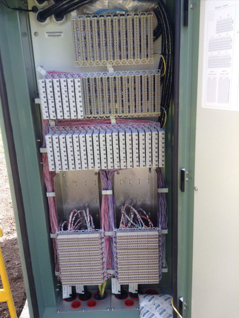
Subscriber lines come in via an IDC distribution frame (Quante IDS) on the right hand side end of the cabinet, accessed through a seperate door.
This frame is referred to as the CCF – Cross Connect Frame.
There are two sets of blocks on the CCF, termination of ‘X’ and ‘C’ Pairs.
‘X’ Pairs are the VF Pairs (PSTN lines) connecting to the pillar where they are jumpered back to the ‘M’ pairs back to the serving exchange,
‘C’ Pairs are the pairs containing combined VDSL & VF services to to the pillar where they are jumpered to the ‘O’ pairs which run out to the customer’s premises,
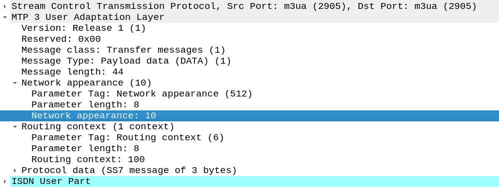
Short one, The other day I needed to add a Network Appearance on an SS7/SS7 M3UA linkset.
Network Appearances on M3UA links are kinda like a port number, in that they allow you to distinguish traffic to the same point code, but handled by different logical entities.
When I added the NA parameter on the Linkset nothing happened.
If you’re facing the same you’ll need to set:
cs7 multi-instance
In the global config (this is the part I missed).
Then select the M3UA linkset you want to change and add the network-appearance parameter:
network-appearance 10
And bingo, you’ll start seeing it in your M3UA traffic:
Last year I purchased a cheap second hand Huawei macro base station – there’s lots of these on the market at the moment due to the fact they’re being replaced in many countries.
I’m using it in my lab environment, and as such the config I’ve got is very “bare bones” and basic. Keep in mind if you’re looking to deploy a Macro eNodeB in production, you may need more than just a blog post to get everything tuned and functioning properly…
In this post we’ll cover setting up a Huawei BTS3900 eNodeB from scratch, using the MML interface, without relying on the U2020 management tool.
Obviously the details I setup (IP Addressing, PLMN and RF parameters) are going to be different to what you’re configuring, so keep that in mind, where I’ve got my MME Addresses, site IDs, TACs, IP Addresses, RFUs, etc, you’ll need to substitute your own values.
A word on Cabinets
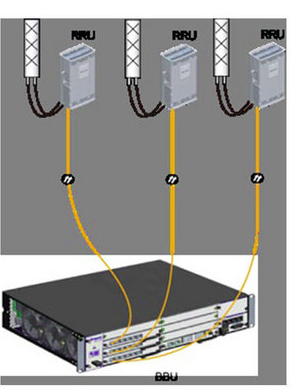
Typically these eNodeBs are shipped in cabinets, that contain the power supplies, alarm / environmental monitoring, power distribution, etc.
Early on in the setup process we’ll be setting the cabinet types we’ve got, and then later on we’ll tell the system what we have installed in which slots.
This is fine if you have a cabinet and know the type, but in my case at least I don’t have a cabinet manufactured by Huawei, just a rack with some kit mounted in it.
This is OK, but it leads to a few gotchas I need to add a cabinet (even though it doesn’t physically exist) and when I setup my RRUs I need to define what cabinet, slot and subrack it’s in, even though it isn’t in any. Keep this in mind as we go along and define the position of the equipment, that if you’re not using a real-world cabinet, the values mean nothing, but need to be kept consistent.
To begin we’ll need to setup the basics, by disabling DHCP and setting an local IP Address for the unit.
 SET DHCPSW: SWITCH=DISABLE;
 SET LOCALIP: IP="192.168.5.234", MASK="255.255.248.0";
Obviously your IP address details will be different. Next we’ll add an eNodeB function, the LMPT / UMPT can have multiple functions and multiple eNodeBs hosted on the same hardware, but in our case we’re just going to configure one:
Again, your eNodeB ID, location, site name, etc, are all going to be different, as will your location.
Next we’ll set the system to maintenance mode (MNTMODE), so we can make changes on the fly (this takes the eNB off the air, but we’re already off the air), you’ll need to adjust the start and end times to reflect the current time for the start time, and end time to be after you’re done setting all this up.
SET MNTMODE: MNTMode=INSTALL, ST=2013&09&20&15&00&00, ET=2013&09&25&15&00&00, MMSetRemark="NewSite Install";
Next we’ll set the operator details, this is the PLMN of the eNodeB, and create a new tracking area.
Next we’ll be setting and populating the cabinets I mentioned earlier. I’ll be telling the unit it’s inside a APM30 (Cabinet 0), and in Cabinet Number 0, Subrack 0, is a BBU3900.
 //To modify the cabinet type, run the following command:
 ADD CABINET:CN=0,TYPE=APM30;
 //Add a BBU3900 subrack, run the following command:
 ADD SUBRACK:CN=0,SRN=0,TYPE=BBU3900;
 //To configure boards and RF datas, run the following commands:
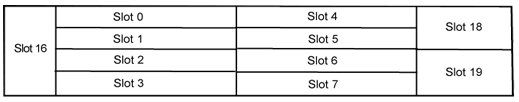
And inside the BBU3900 there’s some cards of course, and each card has as slot, as per the drawing below.
In my environment I’ve got a LMPT in slot 7, and a LBBP in Slot 3. There’s a fan and a UPEU too, so: We’ll add a board in Slot No. 7, of type LMPT, We’ll add a board in Slot No. 3, of type LBBP working on FDD, We’ll add a fan board in Slot No. 16, and a UPEU in Slot No. 18.
Huawei publish design guides for which cards should be in which slots, the general rule is that your LMPT / UMPT card goes in Slot 7, with your BBP cards (UBBP or LBBP) in slots 3, then 2, then 1, then 0. Fans and UPEUs can only go in the slots designed to fit them, so that makes it a bit easier.
Next we’ll need to setup our RRUs, for this we’ll need to setup an RRU chain, which is the Huawei term for the CPRI links and add an RRU into it:
//Modify the reference signal power.
MOD PDSCHCFG: LocalCellId=1, ReferenceSignalPwr=-81;

//Add an operator for the cell.
ADD CELLOP: LocalCellId=0, TrackingAreaId=0;

//Activate the cell.
ACT CELL: LocalCellId=1;
The Binding Support Function is used in 4G and 5G networks to allow applications to authenticate against the network, it’s what we use to authenticate for XCAP and for an Entitlement Server.
Rather irritatingly, there are two BSF addresses in use:
If the ISIM is used for bootstrapping the FQDN to use is:
bsf.ims.mncXXX.mccYYY.pub.3gppnetwork.org
But if the USIM is used for bootstrapping the FQDN is
bsf.mncXXX.mccYYY.pub.3gppnetwork.org
You can override this by setting the 6FDA EF_GBANL (GBA NAF List) on the USIM or equivalent on the ISIM, however not all devices honour this from my testing.
One of the hyped benefits of a 5G Core Networks is that 5GC can be used for wired networks (think DSL or GPON) – In marketing terms this is called “Wireless Wireline Convergence” (5G WWC) meaning DSL operators, cable operators and fibre network operators can all get in on this sweet 5GC action and use this sexy 5G Core Network tech.
This is something that’s in the standards, and that the big kit vendors are pushing heavily in their marketing materials. But will it take off? And should operators of wireline networks (fixed networks) be looking to embrace 5GC?
Comparing 5GC with current wireline network technologies isn’t comparing apples to apples, it’s apples to oranges, and they’re different fruits.
At its heart, the 3GPP Core Networks (including 5G Core) address one particular use cases of the cellular industry: Subscriber mobility – Allowing a customer to move around the network, being served by different kit (gNodeBs) while keeping the same IP Address.
The most important function of 5GC is subscriber mobility.
This is achieved through the use of encapsulating all the subscriber’s IP data into a GTP (A protocol that’s been around since 2G first added data).
Do I need a 5GC for my Fixed Network?
Wireline networks are fixed. Subscribers don’t constantly move around the network. A GPON customer doesn’t need to move their OLT every 30 minutes to a new location.
Encapsulating a fixed subscriber’s traffic in GTP adds significant processing overhead, for almost no gain – The needs of a wireline network operator, are vastly different to the needs of a cellular core.
Today, you can take a /24 IPv4 block, route it to a DSLAM, OLT or CMTS, and give an IP to 254 customers – No cellular core needed, just a router and your access device and you’re done, and this has been possible for decades. Because there’s no mobility the GTP encapsulation that is the bedrock for cellular, is not needed.
Rather than routing directly to Access Network kit, most fixed operators deploy BRAS systems used for fixed access. Like the cellular packet core, BRAS has been around for a very long time, with a massive install base and a sea of engineering experience in house, it meets the needs of the wireline industry who define its functions and roles along with kit vendors of wireline kit; the fixed industry working groups defined the BRAS in the same way the 3GPP and cellular industry working groups defined 5G Core.
I don’t forsee that we’ll see large scale replacement of BRAS by 5GC, for the same reason a wireless operator won’t replace their mobile core with a BRAS and PPPoE – They’re designed to meet different needs.
All the other features that have been added to the 3GPP Core Network functionality, like limiting speed, guaranteed throughput bearers, 5QI / QCI values, etc, are addons – nice-to-haves. All of these capabilities could be implemented in wireline networks today – if the business case and customer demand was there.
But what about slicing?
With dropping ARPUs across the board, additional services relating to QoS (“Network Slicing”) are being held up as the saving grace of revenues for cellular operators and 5G as a whole, however this has yet to be realized and early indications suggest this is not going to be anywhere near as lucrative as previously hoped.
What about cost savings?
In terms of cost-per-bit of throughput, the existing install base wireline operators have of heavy-metal kit capable of terabit switching and routing has been around for some time in fixed world, and is what most 5G Cores will connect to as their upstream anyway, so there won’t be any significant savings on equipment, power consumption or footprint to be gained.
Fixed networks transport the majority of the world’s data today – Wireline access still accounts for the majority of traffic volumes, so wireline kit handles a higher magnitude of throughput than it’s Packet Core / 5GC cousins already.
Cutting down the number of parts in the network is good though right?
If you’re operating both a Packet Core for Cellular, and a fixed network today, then you might think if you moved from the traditional BRAS architecture fore the wired network to 5GC, you could drop all those pesky routers and switches clogging up your CO, Exchanges and Data Centers.
The problem is that you still need all of those after the 5GC to be able to get the traffic anywhere users want to go. So the 5GC will still need all of that kit, all your border routers and peering routers will remain unchanged, as well as domestic transmission, MPLS and transport.
The parts required for operating fixed networks is actually pretty darn small in comparison to that of 5GC.
TL;DR?
While cellular vendors would love to sell their 5GC platform into fixed operators, the premise that they are willing to replace existing BRAS architectures with 5GC, is as unlikely in my view as 5GC being replaced by BRAS.
On the rare occasions I’m not tied to my desk, I’m out for a long run along some back roads somewhere.
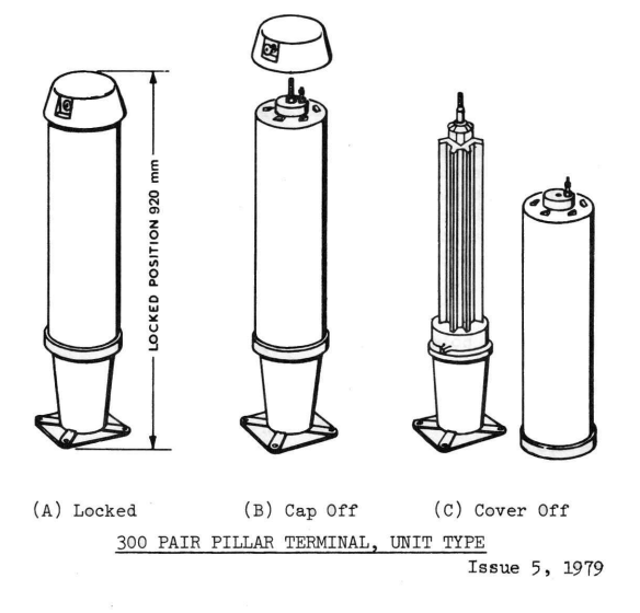
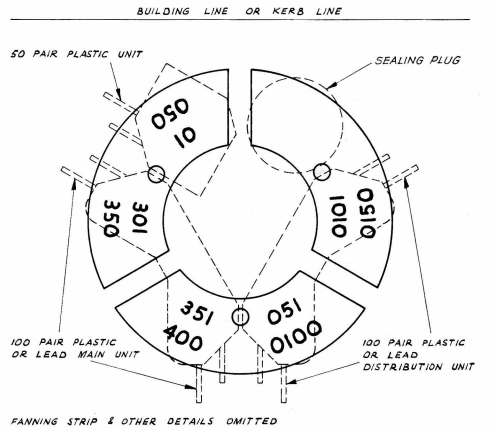
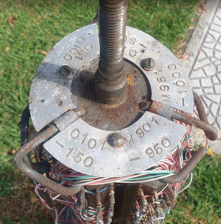
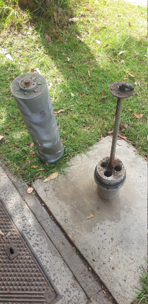
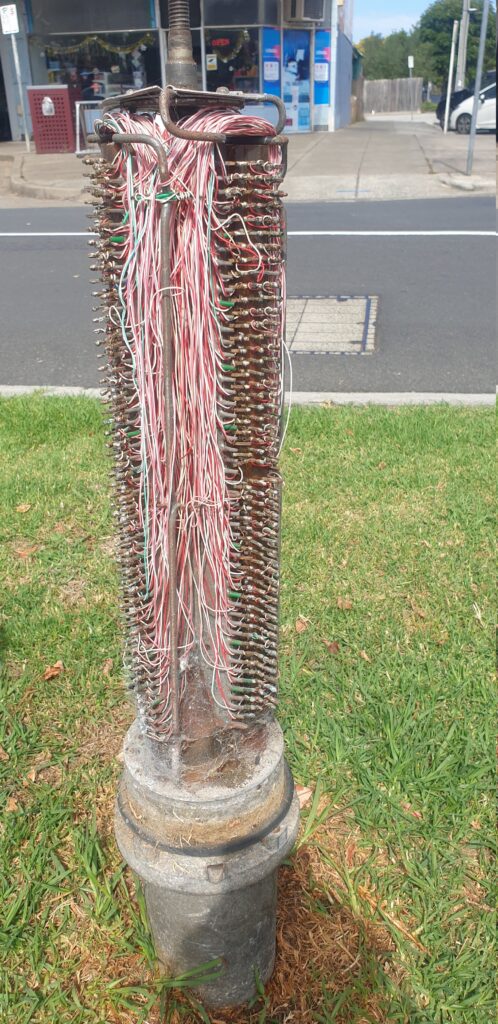
Every now and then I come across these tiny telecom pillars for cross-connection (and don’t shoot at them) – I mostly find them around the edges of distribution areas. I had some recollection that these were originally for trunk lines between exchanges (maybe there was some truth to this?), but some digging in old docs show these were just for interconnecting main or branch cables with distribution cables, in areas where the 600 and 1200 pair pillars / cabinets would be overkill.
They’re built like the 900/1800 pair cabinets, but just scaled down versions, supporting 1x 100 pair main cable, 1x 100 pair distribution cables and 2x 50 pair distribution cables.
It seems like these were largely decomed when NBN took over, leaving most with a big X sprayed on them.
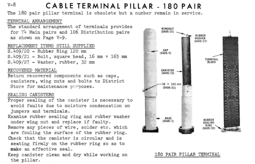
While I was looking through the docs I also found reference to a 180 pair pillar, which looked very similar, but I’ve yet to see any of them left in the wild. Better keep running ’till I find one!
We recently added support in PyHSS for fixed line SIP subscribers to attach to the IMS.
Traditional telecom operators are finding their fixed line network to be a bit of a money pit, something they’re required to keep operating to meet regulatory obligations, but the switches are sitting idle 99% of the time. As such we’re seeing more and more operators move fixed line subs onto their IMS.
This new feature means we can use PyHSS to serve as the brains for a fixed network, as well as for mobile, but there’s one catch – How we authenticate subscribers changes.
Most banks of line cards in a legacy telecom switches, or IP Phones, don’t have SIM slots to allow us to authenticate, so instead we’re forced to fallback to what they do support.
Unfortunately for the most part, what is supported by these IP phones or telecom switches is SIP MD5 Digest Authentication.
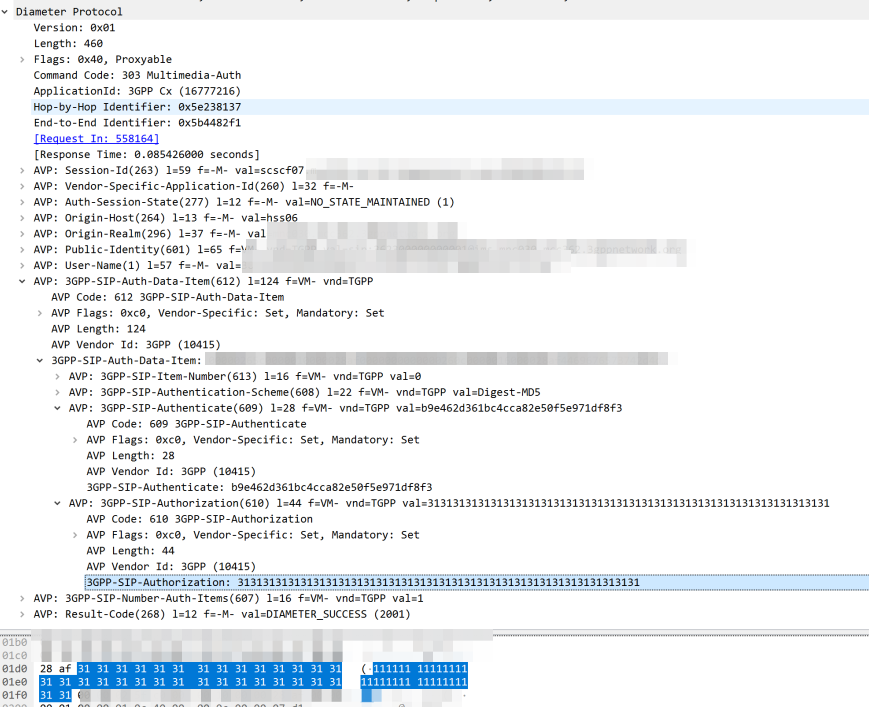
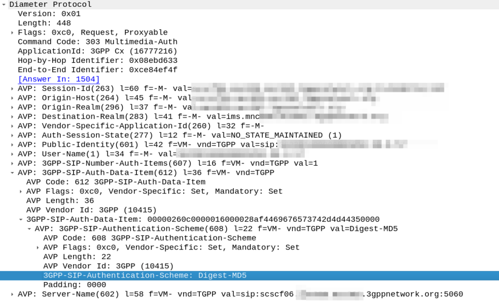
The Nonce is generated by the HSS and put into the Multimedia-Authentication-Answer, along with the subscriber’s password and sent in the clear to the S-CSCF.
The HSS then generates the the Multimedia-Auth Answer, it generates a nonce (in the 3GPP-SIP-Authenticate / 609 AVP) and sends the Subscriber’s password in the 3GPP-SIP-Authorization (610) AVP in response back to the S-CSCF.
I would have thought a better option would be for the HSS to generate the Nonce and Digest, and then the S-CSCF to just send the Nonce to the Sub and compare the returned Digest from the Sub against the expected Digest from the HSS, but it would limit flexibility (realm adaptation, etc) I guess.
The UE/UA (I guess it’s a UA in this context as it’s not a mobile) then generates its own Digest from the Nonce and sends it back to the S-CSCF via the P-CSCF.
The S-CSCF compares the received Digest response against the one it generated, and if the two match, the sub is authenticated and allowed to attach onto the network.