Having a central pair of Diameter routing agents allows us to drastically simplify our network, but what if we want to perform some translations on AVPs?
For starters, what is an AVP transformation? Well it’s simply rewriting the value of an AVP as the Diameter Request/Response passes through the DRA. A request may come into the DRA with IMSI xxxxxx and leave with IMSI yyyyyy if a translation is applied.
So why would we want to do this?
Well, what if we purchased another operator who used Realm X, and we use Realm Y, and we want to link the two networks, then we’d need to rewrite Realm Y to Realm X, and Realm X to Realm Y when they communicate, AVP transformations allow for this.
If we’re an MVNO with hosted IMSIs from an MNO, but want to keep just the one IMSI in our HSS/OCS, we can translate from the MNO hosted IMSI to our internal IMSI, using AVP transformations.
If our OCS supports only one rating group, and we want to rewrite all rating groups to that one value, AVP transformations cover this too.
There are lots of uses for this, and if you’ve worked with a bit of signaling before you’ll know that quite often these sorts of use-cases come up.
So how do we do this with freeDiameter?
To handle this I developed a module for passing each AVP to a Python function, which can then apply any transformation to a text based value, using every tool available to you in Python.
In the next post I’ll introduce rt_pyform and how we can use it with Python to translate Diameter AVPs.
Way back in part 2 we discussed the basic routing logic a DRA handles, but what if we want to do something a bit outside of the box in terms of how we route?
For me, one of the most useful use cases for a DRA is to route traffic based on IMSI / Username. This means I can route all the traffic for MVNO X to MVNO X’s HSS, or for staging / test subs to the test HSS enviroment.
FreeDiameter has a bunch of built in logic that handles routing based on a weight, but we can override this, using the rt_default module.
In our last post we had this module commented out, but let’s uncomment it and start playing with it:
In the above code we’ve uncommented rt_default and rt_redirect.
You’ll notice that rt_default references a config file, so we’ll create a new file in our /etc/freeDiameter directory called rt_default.conf, and this is where the magic will happen.
A few points before we get started:
This overrides the default routing priorities, but in order for a peer to be selected, it has to be in an Open (active) state
The peer still has to have advertised support for the requested application in the CER/CEA dialog
The peers will still need to have all been defined in the freeDiameter.conf file in order to be selected
So with that in mind, and the 5 peers we have defined in our config above (assuming all are connected), let’s look at some rules we can setup using rt_default.
Intro to rt_default Rules
The rt_default.conf file contains a list of rules, each rule has a criteria that if matched, will result in the specified action being taken. The actions all revolve around how to route the traffic.
So what can these criteria match on? Here’s the options:
Item to Match
Code
Any
*
Origin-Host
oh=”STR/REG”
Origin-Realm
or=”STR/REG”
Destination-Host
dh=”STR/REG”
Destination-Realm
dr=”STR/REG”
User-Name
un=”STR/REG”
Session-Id
si=”STR/REG”
rt_default Matching Criteria
We can either match based on a string or a regex, for example, if we want to match anything where the Destination-Realm is “mnc001.mcc001.3gppnetwork.org” we’d use something like:
#Low score to HSS02
dr="mnc001.mcc001.3gppnetwork.org" : dh="hss02" += -70 ;
Now you’ll notice there is some stuff after this, let’s look at that.
We’re matching anything where the destination-host is set to hss02 (that’s the bit before the colon), but what’s the bit after that?
Well if we imagine that all our Diameter peers are up, when a message comes in with Destination-Realm “mnc001.mcc001.3gppnetwork.org”, looking for an HSS, then in our example setup, we have 4 HHS instances to choose from (assuming they’re all online).
In default Diameter routing, all of these peers are in the same realm, and as they’re all HSS instances, they all support the same applications – Our request could go to any of them.
But what we set in the above example is simply the following:
If the Destination-Realm is set to mnc001.mcc001.3gppnetwork.org, then set the priority for routing to hss02 to the lowest possible value.
So that leaves the 3 other Diameter peers with a higher score than HSS02, so HSS02 won’t be used.
Let’s steer this a little more,
Let’s specify that we want to use HSS01 to handle all the requests (if it’s available), we can do that by adding a rule like this:
#Low score to HSS02
dr="mnc001.mcc001.3gppnetwork.org" : dh="hss02" += -70 ;
#High score to HSS01
dr="mnc001.mcc001.3gppnetwork.org" : dh="hss01" += 100 ;
But what if we want to route to hss-lab if the IMSI matches a specific value, well we can do that too.
#Low score to HSS02
dr="mnc001.mcc001.3gppnetwork.org" : dh="hss02" += -70 ;
#High score to HSS01
dr="mnc001.mcc001.3gppnetwork.org" : dh="hss01" += 100 ;
#Route traffic for IMSI to Lab HSS
un="001019999999999999" : dh="hss-lab" += 200 ;
Now that we’ve set an entry with a higher score than hss01 that will be matched if the username (IMSI) equals 001019999999999999, the traffic will get routed to hss-lab.
But that’s a whole IMSI, what if we want to match only part of a field?
Well, we can use regex in the Criteria as well, so let’s look at using some Regex, let’s say for example all our MVNO SIMs start with 001012xxxxxxx, let’s setup a rule to match that, and route to the MVNO HSS with a higher priority than our normal HSS:
#Low score to HSS02
dr="mnc001.mcc001.3gppnetwork.org" : dh="hss02" += -70 ;
#High score to HSS01
dr="mnc001.mcc001.3gppnetwork.org" : dh="hss01" += 100 ;#Route traffic for IMSI to Lab HSS
un="001019999999999999" : dh="hss-lab" += 200 ;
#Route traffic where IMSI starts with 001012 to MVNO HSS
un=["^001012.*"] : dh="hss-mvno-x" += 200 ;
Let’s imagine that down the line we introduce HSS03 and HSS04, and we only want to use HSS01 if HSS03 and HSS04 are unavailable, and only to use HSS02 no other HSSes are available, and we want to split the traffic 50/50 across HSS03 and HSS04.
Firstly we’d need to add HSS03 and HSS04 to our FreeDiameter.conf file:
Then in our rt_default.conf we’d need to tweak our scores again:
#Low score to HSS02
dr="mnc001.mcc001.3gppnetwork.org" : dh="hss02" += 10 ;
#Medium score to HSS01
dr="mnc001.mcc001.3gppnetwork.org" : dh="hss01" += 20 ;
#Route traffic for IMSI to Lab HSS
un="001019999999999999" : dh="hss-lab" += 200 ;
#Route traffic where IMSI starts with 001012 to MVNO HSS
un=["^001012.*"] : dh="hss-mvno-x" += 200 ;
#High Score for HSS03 and HSS04dr="mnc001.mcc001.3gppnetwork.org" : dh="hss02" += 100 ;dr="mnc001.mcc001.3gppnetwork.org" : dh="hss04" += 100 ;
One quick tip to keep your logic a bit simpler, is that we can set a variety of different values based on keywords (listed below) rather than on a weight/score:
Behaviour
Name
Score
Do not deliver to peer (set lowest priority)
NO_DELIVERY
-70
The peer is a default route for all messages
DEFAULT
5
The peer is a default route for this realm
DEFAULT_REALM
10
REALM
15
Route to the specified Host with highest priority
FINALDEST
100
Rather than manually specifying the store you can use keywords like above to set the value
In our next post we’ll look at using FreeDiameter based DRA in roaming scenarios where we route messages across Diameter Realms.
FreeDiameter has been around for a while, and we’ve covered configuring the FreeDiameter components in Open5GS when it comes to the S6a interface, so you may have already come across FreeDiameter in the past, but been left a bit baffled as to how to get it to actually do something.
FreeDiameter is a FOSS implimentation of the Diameter protocol stack, and is predominantly used as a building point for developers to build Diameter applications on top of.
But for our scenario, we’ll just be using plain FreeDiameter.
So let’s get into it,
You’ll need FreeDiameter installed, and you’ll need a certificate for your FreeDiameter instance, more on that in this post.
Once that’s setup we’ll need to define some basics,
Inside freeDiameter.conf we’ll need to include the identity of our DRA, load the extensions and reference the certificate files:
What I typically refer to as Diameter interfaces / reference points, such as S6a, Sh, Sx, Sy, Gx, Gy, Zh, etc, etc, are also known as Applications.
Diameter Application Support
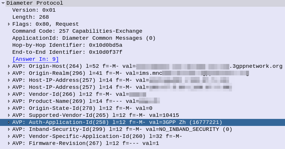
If you look inside the Capabilities Exchange Request / Answer dialog, what you’ll see is each side advertising the Applications (interfaces) that they support, each one being identified by an Application ID.
CER showing support for the 3GPP Zh Application-ID (Interface)
If two peers share a common Application-Id, then they can communicate using that Application / Interface.
For example, the above screenshot shows a peer with support for the Zh Interface (Spoiler alert, XCAP Gateway / BSF coming soon!). If two Diameter peers both have support for the Zh interface, then they can use that to send requests / responses to each other.
This is the basis of Diameter Routing.
Diameter Routing Tables
Like any router, our DRA needs to have logic to select which peer to route each message to.
For each Diameter connection to our DRA, it will build up a Diameter Routing table, with information on each peer, including the realm and applications it advertises support for.
Then, based on the logic defined in the DRA to select which Diameter peer to route each request to.
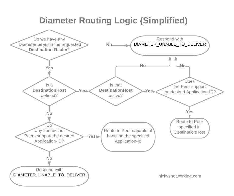
In its simplest form, Diameter routing is based on a few things:
Look at the DestinationRealm, and see if we have any peers at that realm
If we do then look at the DestinationHost, if that’s set, and the host is connected, and if it supports the specified Application-Id, then route it to that host
If no DestinationHost is specified, look at the peers we have available and find the one that supports the specified Application-Id, then route it to that host
Simplified Diameter Routing Table used by DRAs
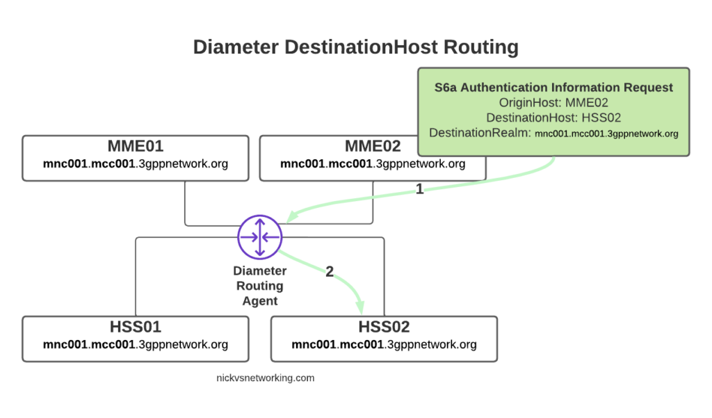
With this in mind, we can go back to looking at how our DRA may route a request from a connected MME towards an HSS.
Let’s look at some examples of this at play.
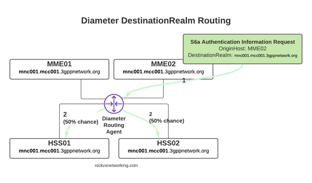
The request from MME02 is for DestinationRealm mnc001.mcc001.3gppnetwork.org, which our DRA knows it has 4 connected peers in (3 if we exclude the source of the request, as we don’t want to route it back to itself of course).
So we have 3 contenders still for who could get the request, but wait! We have a DestinationHost specified, so the DRA confirms the host is available, and that it supports the requested ApplicationId and routes it to HSS02.
So just because we are going through a DRA does not mean we can’t specific which destination host we need, just like we would if we had a direct link between each Diameter peer.
Conversely, if we sent another S6a request from MME01 but with no DestinationHost set, let’s see how that would look.
Again, the request is from MME02 is for DestinationRealm mnc001.mcc001.3gppnetwork.org, which our DRA knows it has 3 other peers it could route this to. But only two of those peers support the S6a Application, so the request would be split between the two peers evenly.
Clever Routing with DRAs
So with our DRA in place we can simplify the network, we don’t need to build peer links between every Diameter device to every other, but let’s look at some other ways DRAs can help us.
Load Control
We may want to always send requests to HSS01 and only use HSS02 if HSS01 is not available, we can do this with a DRA.
Or we may want to split load 75% on one HSS and 25% on the other.
Both are great use cases for a DRA.
Routing based on Username
We may want to route requests in the DRA based on other factors, such as the IMSI.
Our IMSIs may start with 001010001xxx, but if we introduced an MVNO with IMSIs starting with 001010002xxx, we’d need to know to route all traffic where the IMSI belongs to the home network to the home network HSS, and all the MVNO IMSI traffic to the MVNO’s HSS, and DRAs handle this.
Inter-Realm Routing
One of the main use cases you’ll see for DRAs is in Roaming scenarios.
For example, if we have a roaming agreement with a subscriber who’s IMSIs start with 90170, we can route all the traffic for their subs towards their HSS.
But wait, their Realm will be mnc901.mcc070.3gppnetwork.org, so in that scenario we’ll need to add a rule to route the request to a different realm.
DRAs handle this also.
In our next post we’ll start actually setting up a DRA with a default route table, and then look at some more advanced options for Diameter routing like we’ve just discussed.
One slight caveat, is that mutual support does not always mean what you may expect. For example an MME and an HSS both support S6a, which is identified by Auth-Application-Id 16777251 (Vendor ID 10415), but one is a client and one is a server. Keep this in mind!
Answer Question 1: Because they make things simpler and more flexible for your Diameter traffic. Answer Question 2: With free software of course!
All about DRAs
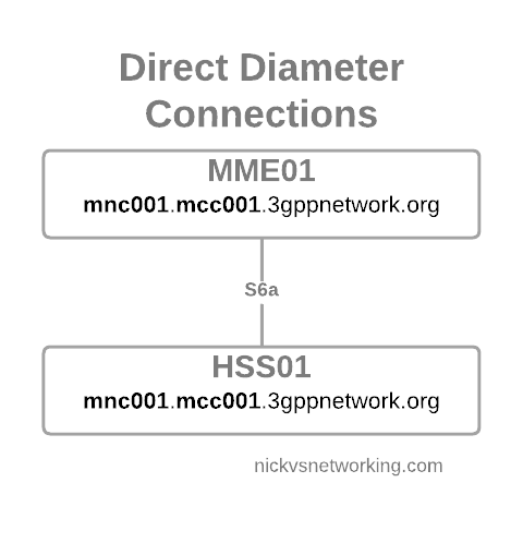
But let’s dive a little deeper. Let’s look at the connection between an MME and an HSS (the S6a interface).
Direct Diameter link between two Diameter Peers
We configure the Diameter peers on MME1 and HSS01 so they know about each other and how to communicate, the link comes up and presto, away we go.
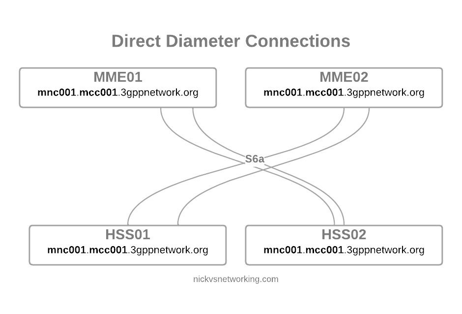
But we’re building networks here! N+1 redundancy and all that, so now we have two HSSes and two MMEs.
Direct Diameter link between 4 Diameter peers
Okay, bit messy, but that’s okay…
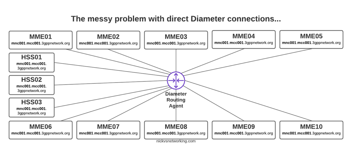
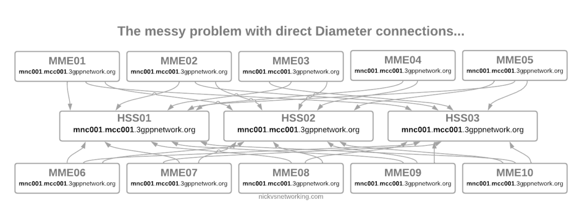
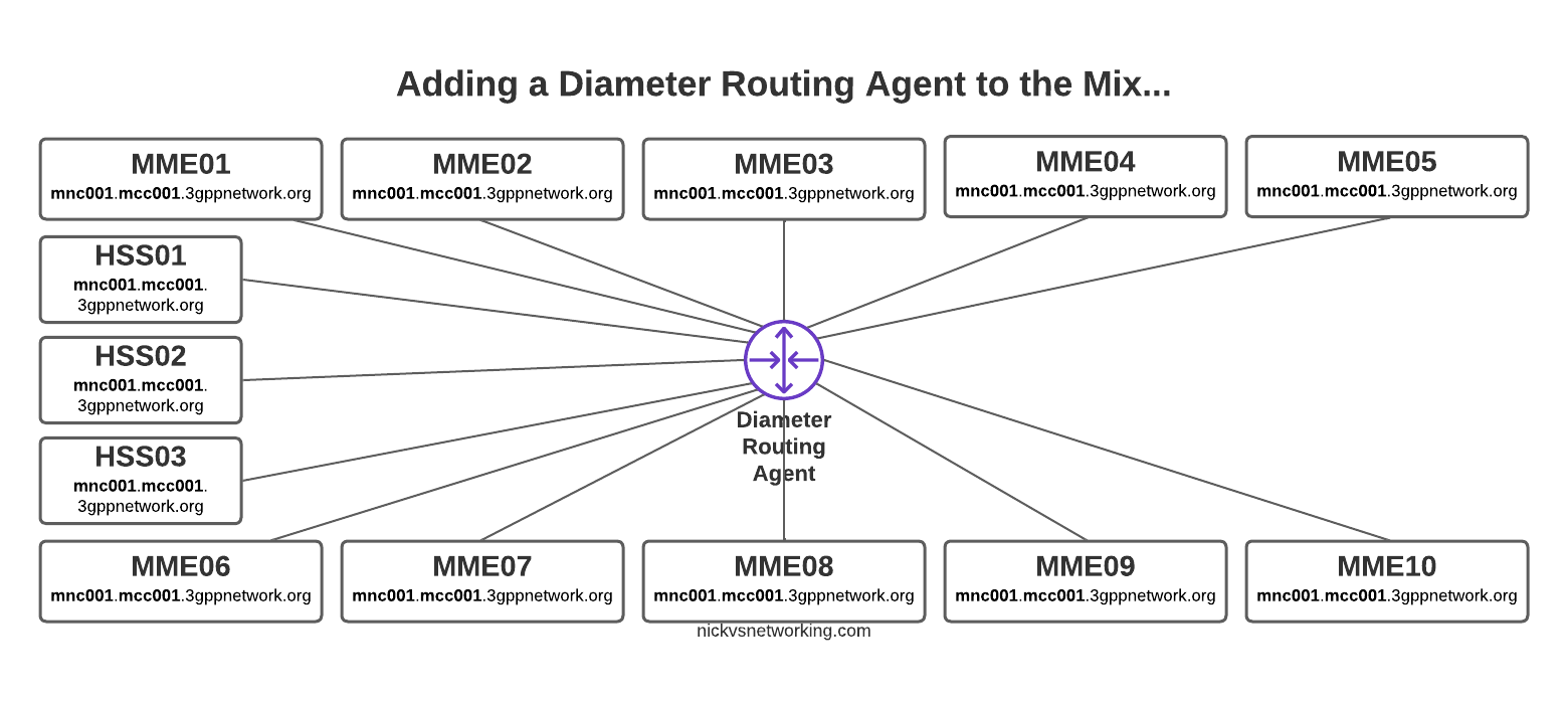
But then our network grows to 10 MMEs, and 3 HSSes and you can probably see where this is going, but let’s drive the point home.
Direct Diameter connections for a network with 10x MME and 3x HSS
Now imagine once you’ve set all this up you need to do some maintenance work on HSS03, so need to shut down the Diameter peer on 10 different MMEs in order to isolate it and deisolate it.
The problem here is pretty evident, all those links are messy, cumbersome and they just don’t scale.
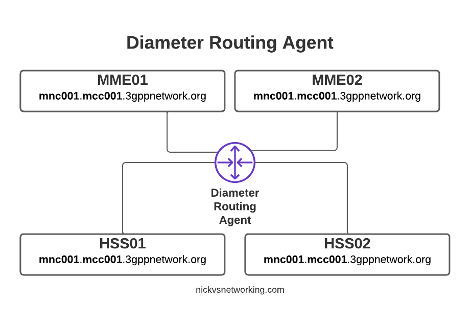
If you’re someone with a bit of networking experience (and let’s face it, you’re here after all), then you’re probably thinking “What if we just had a central system to route all the Diameter messages?”
An Agent that could Route Diameter, a Diameter Routing Agent perhaps…
By introducing a DRA we build Diameter peer links between each of our Diameter devices (MME / HSS, etc) and the DRA, rather than directly between each peer.
With Diameter Routing Agent
Then from the DRA we can route Diameter requests and responses between them.
Let’s go back to our 10x MME and 3x HSS network and see how it looks with a DRA instead.
So much cleaner!
Not only does this look better, but it makes our life operating the network a whole lot easier.
Each MME sends their S6a traffic to the DRA, which finds a healthy HSS from the 3 and sends the requests to it, and relays the responses as well.
We can do clever load balancing now as well.
Plus if a peer goes down, the DRA detects the failure and just routes to one of the others.
If we were to introduce a new HSS, we wouldn’t need to configure anything on the MMEs, just add HSS04 to the DRA and it’ll start getting traffic.
Plus from an operations standpoint, now if we want to to take an HSS offline for maintenance, we just shut down the link on the HSS and all HSS traffic will get routed to the other two HSS instances.
In our next post we’ll talk about the Routing part of the DRA, how the decisions are made and all the nuances, and then in the following post we’ll actually build a DRA and start routing some traffic around!
If you work with IMS or Packet Core, there’s a good chance you need DNS to work, and it doesn’t always.
When I run traces, I’ve always found I get swamped with DNS traffic, UE traffic, OS monitoring, updates, etc, all combine into a big firehose – while my Wireshark filters for finding EPC and IMS traffic is pretty good, my achilles heel has always been filtering the DNS traffic to just get the queries and responses I want out of it.
Well, today I made that a bit better.
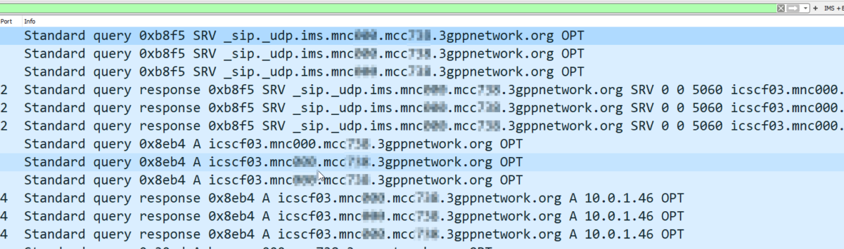
By adding this to your Wireshark filter:
dns contains 33:67:70:70:6e:65:74:77:6f:72:6b:03:6f:72:67:00
You’ll only see DNS Queries and Responses for domains at the 3gppnetwork.org domain.
This makes my traces much easier to read, and hopefully will do the same for you!
Bonus, here’s my current Wireshark filter for working EPC/IMS:
(diameter and diameter.cmd.code != 280) or (sip and !(sip.Method == "OPTIONS") and !(sip.CSeq.method == "OPTIONS")) or (smpp and (smpp.command_id != 0x00000015 and smpp.command_id != 0x80000015)) or (mgcp and !(mgcp.req.verb == "AUEP") and !(mgcp.rsp.rspcode == 500)) or isup or sccp or rtpevent or s1ap or gtpv2 or pfcp or (dns contains 33:67:70:70:6e:65:74:77:6f:72:6b:03:6f:72:67:00)
Even if you’re not using TLS in your FreeDiameter instance, you’ll still need a certificate in order to start the stack.
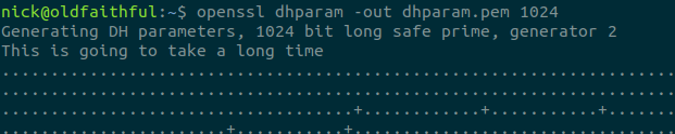
Luckily, creating a self-signed certificate is pretty simple,
Firstly we generate your a private key and public certificate for our required domain – in the below example I’m using dra01.epc.mnc001.mcc001.3gppnetwork.org, but you’ll need to replace that with the domain name of your freeDiameter instance.
If you’re using freeDiameter as part of another software stack (Such as Open5Gs) the below filenames will contain the config for that particular freeDiameter components of the stack:
The Wiki on the Sangoma documentation page is really out of date and can’t be easily edited by the public, so here’s the skinny on how to setup a Sangoma transcoding card on a modern Debian system:
apt-get install libxml2* wget make gcc
wget https://ftp.sangoma.com/linux/transcoding/sng-tc-linux-1.3.11.x86_64.tgz
tar xzf sng-tc-linux-1.3.11.x86_64.tgz
cd sng-tc-linux-1.3.11.x86_64/
make
make install
cp lib/* /usr/local/lib/
ldconfig
At this point you should be able to check for the presence of the card with:
sngtc_tool -dev ens33 -list_modules
Where ens33 is the name of the NIC that the server that shares a broadcast domain with the transcoder.
Successfully discovering the Sangoma D150 transcoder
If instead you see something like this:
root@fs-131:/etc/sngtc#  sngtc_tool -dev ens33 -list_modules
Failed to detect and initialize modules with size 1
That means the server can’t find the transcoding device. If you’re using a D150 (The Ethernet enabled versions) then you’ve got to make sure that the NIC you specified is on the same VLAN / broadcast domain as the server, for testing you can try directly connecting it to the NIC.
I also found I had to restart the device a few times to get it to a “happy” state.
It’s worth pointing out that there are no LEDs lit when the system is powered on, only when you connect a NIC.
Next we’ll need to setup the sngtc_server so these resources can be accessed via FreeSWITCH or Asterisk.
Config is pretty simple if you’re using an all-in-one deployment, all you’ll need to change is the NIC in a file you create in /etc/sngtc/sngtc_server.conf.xml:
<configuration name="sngtc_server.conf" description="Sangoma Transcoding Manager Configuration">

        <settings>
                <!--
                By default the SOAP server uses a private local IP and port that will work for out of the box installations
                where the SOAP client (Asterisk/FreeSWITCH) and server (sngtc_server) run in the same box.
                However, if you want to distribute multiple clients across the network, you need to edit this values to
                listen on an IP and port that is reachable for those clients.
                <param name="bindaddr" value="0.0.0.0" />
                <param name="bindport" value="9000" />
                -->
        </settings>

        <vocallos>

                <!-- The name of the vocallo is the ethernet device name as displayed by ifconfig -->
                <vocallo name="ens33">
                        <!-- Starting UDP port for the vocallo -->
                        <param name="base_udp" value="5000"/>
                        <!-- Starting IP address octet to use for the vocallo modules -->
                        <param name="base_ip_octet" value="182"/>
                </vocallo>

        </vocallos>


</configuration>
With that set we can actually try starting the server,
Again, all going well you should see something like this in the log:
Long after humans reduce this planet to an inhospitable wasteland, cockroaches and my Lenovo ThinkPad will continue to survive.
My only gripe with my almost decade old laptop, is the charger. It has a standalone charger, and I can’t charge it on USB-C.
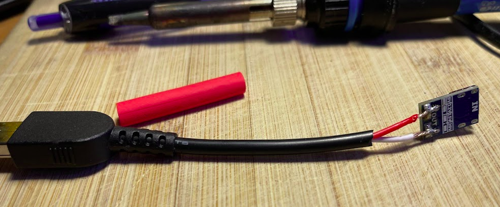
Way back in when Lenovo took over from IBM, the barrel jack style charger that ThinkPads had used was replaced with a slimmer rectangular charger port, to allow for more slimmer laptops. You can get adapters to allow you to use your old chargers with the new(er) laptops, and luckily for us, this means we have a cheap and readily available source of male slimline charger plugs, without having to resort to cutting up a charger.
And for a few bucks online, you can buy USB-C Power Delivery converters that you plug USB-C into one end of, and get out 20v on the other side…
USB-C to 20v Power Delivery module
So I combined the two; USB-C to 20v adapter on one side, and a cut up barrel-charger to slimline charger adapter on the other using the male slimline charger plug.
And bingo, just like that I’ve got a USB-C charging capability for my Thinkpad.
After potting in silicone, I’ve got something that can go in my backpack and allow me to charge my laptop on the go with a USB-C charger, for under $5 of parts.
Well, there’s another concept I haven’t introduced yet, and that’s ChargerS, this is a concept / component we’ll dig into deeper for derived charging, but for now just know we need to add a ChargerS rule in order to get CDRs rated:
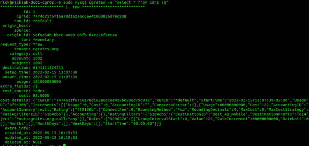
Well, if you’ve got CDR storage in StoreDB enabled (And you probably do if you’ve been following up until this point), then the answer is a MySQL table, and we can retrive the data with:
sudo mysql cgrates -e "select * from cdrs \G"
For those of you with a bit of MySQL experience under your belt, you’d be able to envisage using the SUM function to total a monthly bill for a customer from this.
Of course we can add CDRs via the API, and you probably already guessed this, but we can retrive CDRs via the API as well, filtering on the key criteria:
This would be useful for generating an invoice or populating recent calls for a customer portal.
Maybe creating rated CDRs and sticking them into a database is exactly what you’re looking to achieve in CGrateS – And if so, great, this is where you can stop – but for many use cases, there’s a want for an automated solution – For your platform to automatically integrate with CGrateS.
If you’ve got an Asterisk/FreeSWITCH/Kamailio or OpenSIPs based platform, then you can integrate CGrateS directly into your platform to add the CDRs automatically, as well as access features like prepaid credit control, concurrent call limits, etc, etc. The process is a little different on each of these platforms, but ultimately under the hood, all of these platforms have some middleware that generates the same API calls we just ran to create the CDR.
So far this tutorial has been heavy on teaching the API, because that’s what CGrateS ultimately is – An API service.
Our platforms like Asterisk and Kamailio with the CGrateS plugins are just CGrateS API clients, and so once we understand how to use and interact with the API it’s a breeze to plug in the module for your platform to generate the API calls to CGrateS required to integrate.
I build phone networks, and unfortunately, I’m not able to be everywhere at once.
This means sometimes I have to test things in networks I may not be within the coverage of.
To get around this, I’ve setup something pretty simple, but also pretty powerful – Remote test phones.
Using a Raspberry Pi, Intel NUC, or any old computer, I’m able to remotely control Android handsets out in the field, in the coverage footprint of whatever network I need.
This means I can make test calls, run speed testing, signal strength measurements, on real phones out in the network, without leaving my office.
Base OS
Because of some particularities with Wayland and X11, for this I’d steer clear of Ubuntu distributions, and suggest using Debian if you’re using x86 hardware, and Raspbian if you’re using a Pi.
Setup Android Debug Bridge (adb)
The base of this whole system is ADB, the Android Debug Bridge, which exposes the ability to remotely control an Android phone over USB.
You can also do this over WiFi, but I find for device testing, wired allows me to airplane mode a device or disable data, which I can’t do if the device is connected to ADB via WiFi.
There’s lot of info online about setting Android Debug Bridge up on your device, unlocking the Developer Mode settings, etc, if you’ve not done this before I’ll just refer you to the official docs.
Before we plug in the phones we’ll need to setup the software on our remote testing machine, which is simple enough:
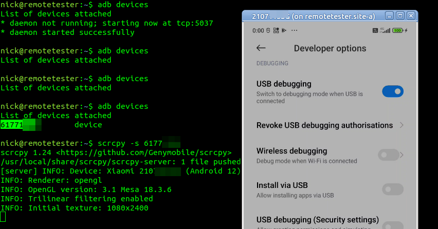
Now we can plug in each of the remote phones we want to use for testing and run the command “adb devices” which should list the phones with connected to the machine with ADB enabled:
[email protected]:~$ adb devices
List of devices attached
ABCDEFGHIJK	unauthenticated
LMNOPQRSTUV	unauthenticated
You’ll get a popup on each device asking if you want to allow USB debugging – If this is going to be a set-and-forget deployment, make sure you tick “Always allow from this Computer” so you don’t have to drive out and repeat this step, and away you go.
Lastly we can run adb devices again to confirm everything is in the connected state
Scrcpy
scrcpy an open-source remote screen mirror / controller that allows us to control Android devices from a computer.
In our case we’re going to install with Snap (if you hate snaps as many folks do, you can also compile from source):
After SSHing into the box, we can just run scrcpy and boom, there’s the window we can interact with.
If you’ve got multiple devices connected to the same device, you’ll need to specify the ADB device ID, and of course, you can have multiple sessions open at the same time.
scrcpy -s 61771fe5
That’s it, as simple as that.
Tweaking
A few settings you may need to set:
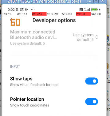
I like to enable the “Show taps” option so I can see where my mouse is on the touchscreen and see what I’ve done, it makes it a lot easier when recording from the screen as well for the person watching to follow along.
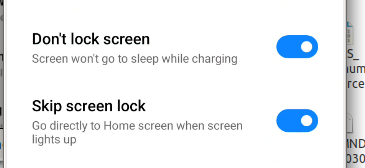
You’ll probably also want to disable the lock screen and keep the screen awake
Some OEMs have an additonal tick box if you want to be able to interact with the device (rather than just view the screen), which often requires signing into an account, if you see this toggle, you’ll need to turn it on:
Ansible Playbook
I’ve had to build a few of these, so I’ve put an Ansible Playbook on Github so you can create your own.
In our last post we introduced the CGrateS API and we used it to add Rates, Destinations and define DestinationRates.
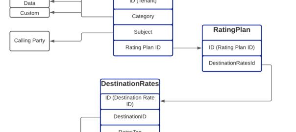
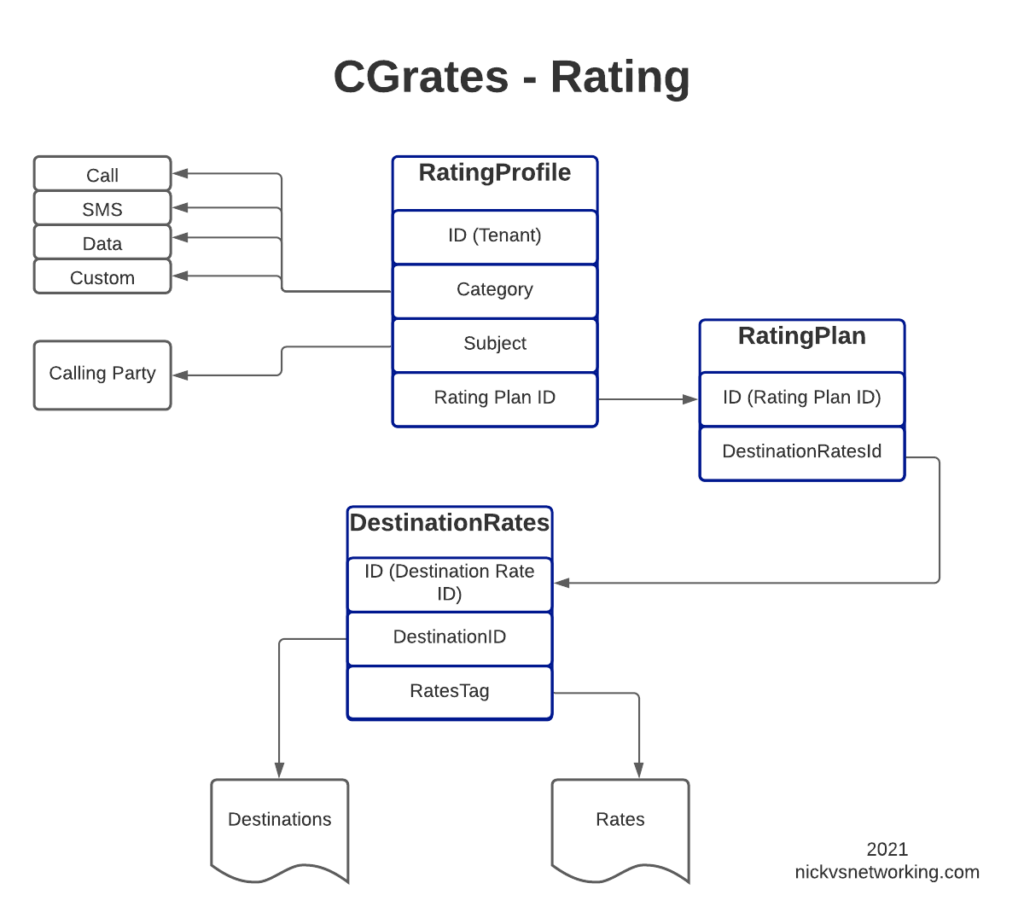
In this post, we’ll create the RatingPlan that references the DestinationRate we just defined, and the RatingProfile that references the RatingPlan, and then, as the cherry on top – We’ll rate some calls.
For anyone looking at the above diagram for the first time, you might be inclined to ask why what is the purpose of having all these layers?
This layered architecture allows all sorts of flexibility, that we wouldn’t otherwise have, for example, we can have multiple RatingPlans defined for the same Destinations, to allow us to have different Products defined, with different destinations and costs.
Likewise we can have multiple RatingProfiles assigned for the same destinations to allow us to generate multiple CDRs for each call, for example a CDR to bill the customer with and a CDR with our wholesale cost.
All this flexibility is enabled by the layered architecture.
Define RatingPlan
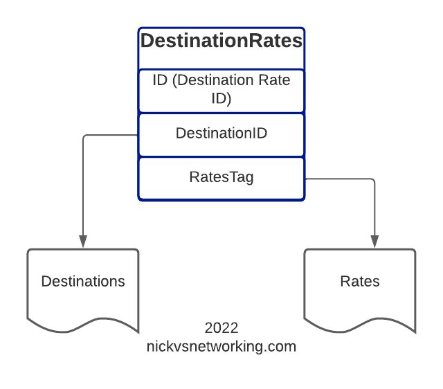
Picking up where we left off having just defined the DestinationRate, we’ll need to create a RatingPlan and link it to the DestinationRate, so let’s check on our DestinationRates:
From the output we can see we’ve got the DestinationRate defined, there’s a lot of info returned (I’ve left out most of it), but you can see the Destination, and the Rate associated with it is returned:
So after confirming that our DestinationRates are there, we’ll create a RatingPlan to reference it, for this we’ll use the APIerSv1.SetTPRatingPlan API call.
In our basic example, this really just glues the DestinationRate_AU object to RatingPlan_VoiceCalls.
It’s worth noting that you can use a RatingPlan to link to multiple DestinationRates, for example, we might want to have a different RatingPlan for each region / country, we can do that pretty easily too, in the below example I’ve referenced other Destination Rates (You’d go about defining the DestinationRates for these other destinations / rates the same way as we did in the last example).
One last step before we can test this all end-to-end, and that’s to link the RatingPlan we just defined with a RatingProfile.
StorDB & DataDB
Psych! Before we do that, I’m going to subject you to learning about backends for a while.
So far we’ve skirted around CGrateS architecture, but this is something we need to know for now.
To keep everything fast, a lot of data is cached in what is called a DataDB (if you’ve followed since part 1, then your DataDB is Redis, but there are other options).
To keep everything together, databases are used for storage, called StorDB (in our case we are using MySQL, but again, we can have other options) but calls to this database are minimal to keep the system fast.
If you’re an astute reader, you may have noticed many of our API calls have TP in method name, if the API call has TP in the name, it is storing it in the StoreDB, if it doesn’t, it means it’s storing it only in DataDB.
Why does this matter? Well, let’s look a little more closely and it will become clear:
ApierV1.SetRatingProfile will set the data only in DataDB (Redis), because it’s in the DataDB the change will take effect immediately.
ApierV1.SetTPRatingProfile will set the data only in StoreDB (MySQL), it will not take effect until it is copied from the database (StoreDB) to the cache (DataDB).
After we define the RatingPlan, we need to run this command prior to creating the RatingProfile, so it has something to reference, so we’ll do that by adding:
The last piece of the puzzle to define is the RatingProfile.
We define a few key things in the rating profile:
The Tenant – CGrateS is multitenant out of the box (in our case we’ve used tenant named “cgrates.org“, but you could have different tenants for different customers).
The Category – As we covered in the first post, CGrateS can bill voice calls, SMS, MMS & Data consumption, in this scenario we’re billing calls so we have the value set to *call, but we’ve got many other options. We can use Category to link what RatingPlan is used, for example we might want to offer a premium voice service with guaranteed CLI rates, using a different RatingPlan that charges more per call, or maybe we’re doing mobile and we want a different RatingPlan for use when Roaming, we can use Category to switch that.
The Subject – This is loosely the Source / Calling Party; in our case we’re using a wildcard value *any which will match any Subject
The RatingPlanActivations list the RatingPlanIds of the RatingPlans this RatingProfile uses
So let’s take a look at what we’d run to add this:
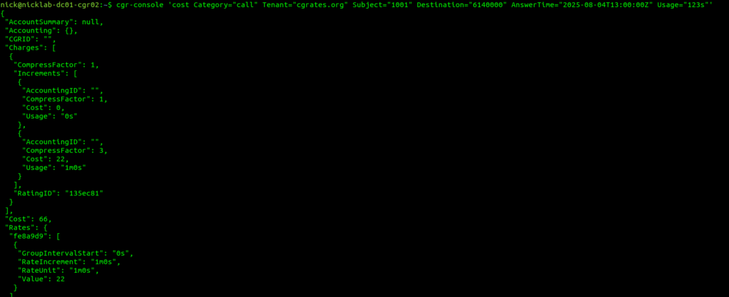
Okay, so at this point, all going well, we should have some data loaded, we’ve gone through all those steps to load this data, so now let’s simulate a call to a Mobile Number (22c per minute) for 123 seconds.
We cheated a fair bit, to show something that worked, but it’s not something you’d probably want to use in real life, loading static CSV files gets us off the ground, but in reality we don’t want to manage a system through CSV files.
Instead, we’d want to use an API.
Fair warning – There is some familiarity expected with JSON and RESTful APIs required, we’ll use Python3 for our examples, but you can use any programing language you’re comfortable with, or even CURL commands.
So we’re going to start by clearing out all the data we setup in CGrateS using the cgr-loader tool from those imported CSVs:
redis-cli flushall
sudo mysql -Nse 'show tables' cgrates | while read table; do sudo mysql -e "truncate table $table" cgrates; done
cgr-migrator -exec=*set_versions -stordb_passwd=CGRateS.org
sudo systemctl restart cgrates
So what have we just done? Well, we’ve just cleared all the data in CGrateS. We’re starting with a blank slate.
In this post, we’re going to define some Destinations, some Rates to charge and then some DestinationRates to link each Destination to a Rate.
But this time we’ll be doing this through the CGrateS API.
Introduction to the CGrateS API
CGrateS is all API driven – so let’s get acquainted with this API.
I’ve written a simple Python wrapper you can find here that will make talking to CGRateS a little easier, so let’s take it for a spin and get the Destinations that are loaded into our system:
import cgrateshttpapi
CGRateS_Obj = cgrateshttpapi.CGRateS('172.16.41.133', 2080) #Replace this IP with the IP Address of your CGrateS instance...

destinations = CGRateS_Obj.SendData({'method':'ApierV1.GetTPDestinationIDs','params':[{"TPid":"cgrates.org"}]})['result']

#Pretty print the result:
print("Destinations: ")
pprint.pprint(destinations)
All going well you’ll see something like this back:
Initializing with host 172.16.41.133 on port 2080
Sending Request with Body:
{'method': 'ApierV2.Ping', 'params': [{'Tenant': 'cgrates.org'}]}
Sending Request with Body:
{'method': 'ApierV2.GetTPDestinationIDs', 'params': [{"TPid":"cgrates.org"}]}
Destinations from CGRates: []
So what did we just do? Well, we sent a JSON formatted string to the CGRateS API at 172.16.41.133 on port 2080 – You’ll obviously need to change this to the IP of your CGrateS instance.
In the JSON body we sent we asked for all the Destinations using the ApierV1.GetTPDestinationIDs method, for the TPid ‘cgrates.org’,
And it looks like no destinations were sent back, so let’s change that!
Note: There’s API Version 1 and API Version 2, not all functions exist in both (at least not in the docs) so you have to use a mix.
Adding Destinations via the API
So now we’ve got our API setup, let’s see if we can add a destination!
To add a destination, we’ll need to go to the API guide and find the API call to add a destination – in our case the API call is ApierV2.SetTPDestination and will look like this:
So we’re creating a Destination named Dest_AU_Mobile and Prefix 614 will match this destination.
Note: I like to prefix all my Destinations with Dest_, all my rates with Rate_, etc, so it makes it easy when reading what’s going on what object is what, you may wish to do the same!
So we’ll use the Python code we had before to list the destinations, but this time, we’ll use the ApierV2.SetTPDestination API call to add a destination before listing them, let’s take a look:
If we post this to the CGR engine, we’ll create a rate, named Rate_AU_Mobile_Rate_1 that bills 22 cents per minute, charged every 60 seconds.
Let’s add a few rates:
CGRateS_Obj.SendData({"method":"ApierV1.SetTPRate","params":[{"ID":"Rate_AU_Mobile_Rate_1","TPid":"cgrates.org","RateSlots":[{"ConnectFee":0,"Rate":22,"RateUnit":"60s","RateIncrement":"60s","GroupIntervalStart":"0s"}]}],"id":1})
CGRateS_Obj.SendData({"method":"ApierV1.SetTPRate","params":[{"ID":"Rate_AU_Fixed_Rate_1","TPid":"cgrates.org","RateSlots":[{"ConnectFee":0,"Rate":14,"RateUnit":"60s","RateIncrement":"60s","GroupIntervalStart":"0s"}]}],"id":1})
CGRateS_Obj.SendData({"method":"ApierV1.SetTPRate","params":[{"ID":"Rate_AU_Toll_Free_Rate_1","TPid":"cgrates.org","RateSlots":[{"ConnectFee":25,"Rate":0,"RateUnit":"60s","RateIncrement":"60s","GroupIntervalStart":"0s"}]}],"id":1})

TPRateIds = CGRateS_Obj.SendData({"method":"ApierV1.GetTPRateIds","params":[{"TPid":"cgrates.org"}]})['result']
print(TPRateIds)
for TPRateId in TPRateIds:
    print("\tRate: " + str(TPRateId))
All going well, when you add the above, we’ll have added 3 new rates:
Rate Name
Cost
Rate_AU_Fixed_Rate_1
14c per minute charged every 60s
Rate_AU_Mobile_Rate_1
22c per minute charged every 60s
Rate_AU_Toll_Free_Rate_1
25c connection, untimed
Rates we just created
Linking Rates to Destinations
So now with Destinations defined, and Rates defined, it’s time to link these two together!
Destination Rates link our Destinations and Route rates, this decoupling means that we can have one Rate shared by multiple Destinations if we wanted, and makes things very flexible.
For this example, we’re going to map the Destinations to rates like this:
All going well, you’ll see the new DestinationRate we added.
Here’s a good chance to show how we can add multiple bits of data in one API call, we can tweak the ApierV1.SetTPDestinationRate method and include all the DestinationRates we need in one API call:
In our next post, we’ll keep working our way up this diagram, by creating RatingPlans and RatingProfiles to reference the DestinationRate we just created.
In our last post we talked about setting rates in CGrates and testing them out, but what’s the point in learning a charging system without services to charge?
This post focuses on intergrating FreeSWITCH and CGrates, other posts cover integrating Asterisk and CGrates, Kamailio and CGrates and Diameter and CGrates.
Future posts in this series will focus on the CGrates side, but this post will be a bit of a sidebar to get our FreeSWITCH environment connected to CGrates so we can put all our rating and charging logic into FreeSWITCH.
CGrates interacts with FreeSWITCH via the Event-Socket-Language in FreeSWITCH, which I’ve written about before, in essence when enabled, CGrates is able to make decisions regarding if a call should proceed or not, monitor currently up calls, and terminate calls when a subscriber has used their allocated balance.
Adding ESL Binding Support in FreeSWITCH
The configuration for CGrates is defined through the cgrates.json file in /etc/cgrates on your rating server.
By default, FreeSWITCH’s event socket only listens on localhost, as it is a pretty huge security flaw to open it to the world, but in order for our CGrates server to be able to access we’ll need to bind it to an IP Address assigned to the FreeSWITCH server so we can reach it from elsewhere on the network.
You may want to have CGrates installed on a different machine to your FreeSWITCH instance, or you may want to have multiple FreeSWITCH instances all getting credit control from CGrates.
Well, inside the cgrates.json config file, is where we populate the ESL connection details so CGrates can connect to FreeSWITCH.
Next we’ll need to tag the extensions we want to charge,
In order to do this we’ll need to set the type of the account (Ie. Prepaid, Postpaid, etc), and the flags to apply, which dictate which of the modules we’re going to use inside CGrateS.
FreeSWITCH won’t actually parse this info, it’s just passed to CGrateS.
And that’s pretty much it, when you restart FreeSWITCH and CGrates you should see in the CGrates log that it is connected to your FreeSWITCH instance, and when you make a call, FreeSWITCH will authorize it through CGrates.
We’ll get back into the nitty gritty about setting up CGrates in a future post, and cover setting up integration like this with other Platforms (Kamailio / Asterisk) and Protocols (Diameter & Radius) in future posts.
Carl Sagan once famously said “If you wish to make an apple pie from scratch, you must first invent the universe”, we don’t need to go that far back, but if you want to deliver an MMS to a subscriber, first you must deliver an SMS.
Wait, but we’re talking about MMS right? So why are we talking SMS?
Modern MMS transport relies on HTTP, which is client-server based, the phone / UE is the client, and the MMSc is the Server.
The problem with this client-server relationship, is the client requests things from the server, but the server can’t request things from the client.
This presents a problem when it comes to delivering the MMS – The phone / UE will need to request the MMSc provide it the message to be received, but needs to know there is a message to request in the first place.
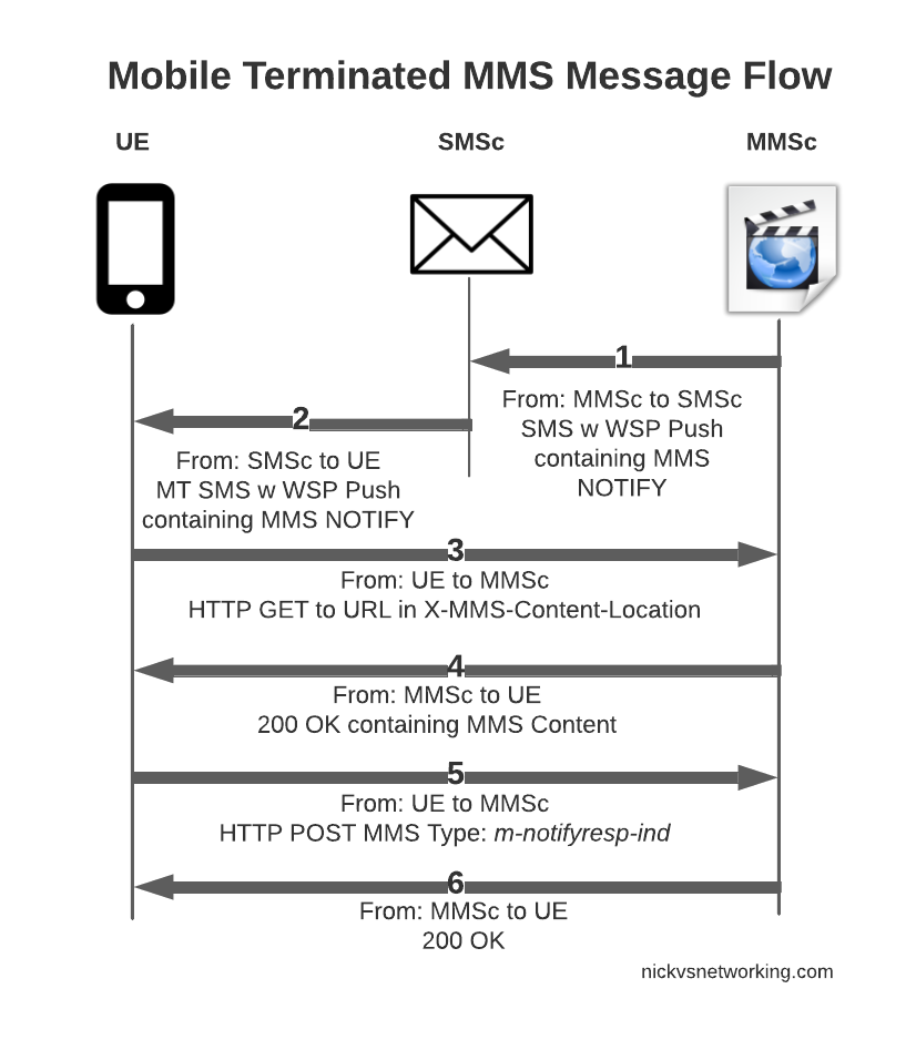
So this is where SMS comes in. When the MMSc has a message destined for a Subscriber, it sends the phone/UE an SMS, informing that there is an MMS waiting, and providing the URL the MMS can be retrieved from.
This is typically done by MAP or SMPP, to link the MMSc to the SMSc to allow it to send these messages.
This SMS contains the URL to retrieve the MMS at, once the UE receives this SMS, it knows where to retrieve the MMS.
It can then send an HTTP GET to the URL to retrieve the MMS, and lastly sends an HTTP POST to confirm to the MMSc it retrieved it all OK.
MMS Mobile Terminated message flow
So that’s the basics, let’s look at each part of the dialog in some more detail, starting with this magic SMS to tell the UE where to retrieve the MMS from.
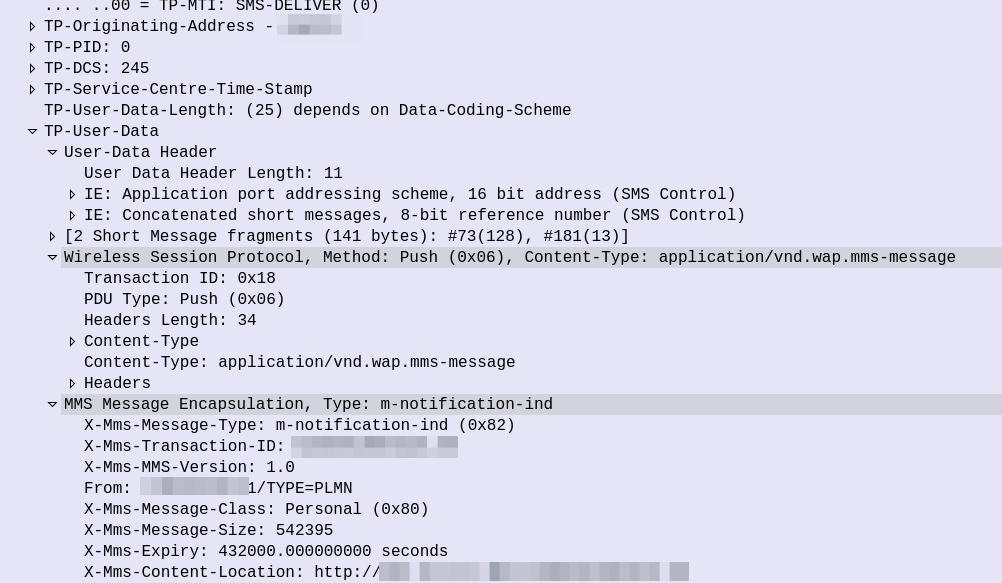
WAP PUSH from MMSc sent via SMS
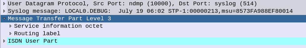
So some things to notice, the user data, which would usually carry the body of our SMS instead contains another protocol, “Wireless Session Protocol” (WSP), and this is the method “Push”.
That in turn is followed by MMS Message Encapsulation, again inside the SMS message body, this time with the MMS specific data.
The From: header contains the sender of the MMS, this is how you can see who the MMS is from, while it’s still downloading.
The expiry indicates to the handset, it it doesn’t download the MMS within the specified time period, it shouldn’t bother, as the message will have expired.
And lastly, and perhaps most importantly, we have the X-MMS-Content-Location header, which tells our subscriber where to download the MMS from.
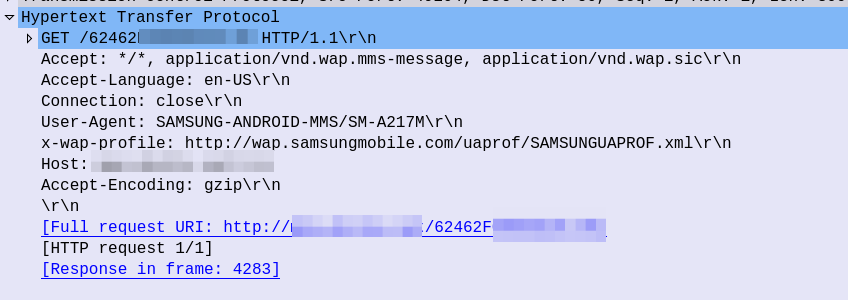
After this, the UE sends an HTTP GET to the URL in the X-MMS-Content-Location header (typically on the “mms” APN), to retrieve the MMS from the MMSc.
HTTP GET from the UE to the MMSc
The HTTP GET is pretty normal, there’s the usual MMS headers we talked about in the last post, and we just GET the path provided by the MMSc in the WAP PUSH.
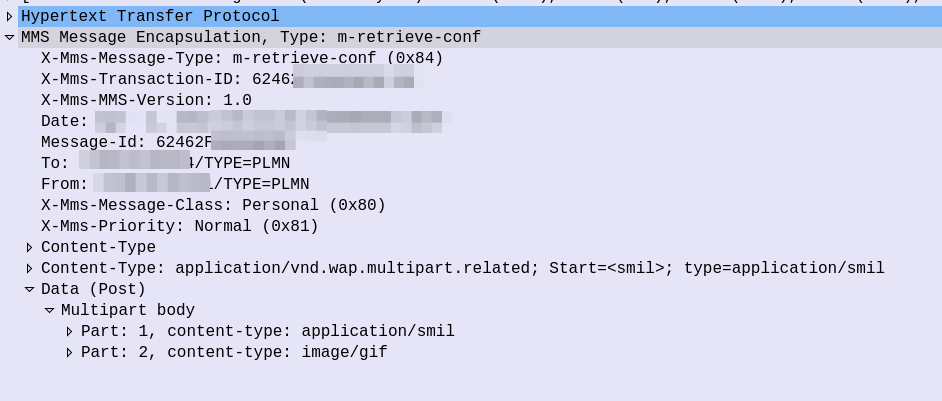
The response from the MMSc contains the actual MMS itself, which is almost a mirror of the sending process (the Data component is unchanged from when the sender sent it).
Response to HTTP GET for message retrieval
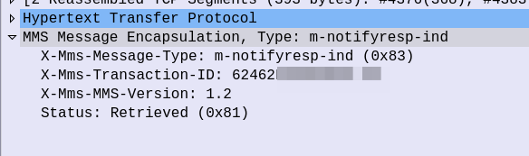
At this stage our subscriber has retrieve the MMS, but may not have retrieved it fully, or may have had an issue retrieving it.
Instead the UE sends an HTTP POST with the MMS-Message-Type m-notifyresp-ind with the transaction ID, to indicate that it has successfully retrieved the MMS, and at this point the MMS can notify the sender if delivery receipts are enabled, and delete the message from the cache.
And finally the MMSc sends back a 200 OK with no body to confirm it got that too.
Some notes on MMS Security
Reading about unauthenticated GET requests, you may be left wondering what security does MMS have, and what stops you from just going through and sending HTTP GET requests to all the possible URL paths to vacuum up all the MMS?
In the standard, nothing!
Typically the MMSc has some layer of security added by the implementer, to ensure the user retrieving the MMS, is the user the MMS is destined for. Because MMS has no security in the standard, this is typically achieved through Header Enrichment, whereby the P-GW adds a HTTP header with the MSISDN or IMSI of the subscriber, and then the MMSc can evaluate if this subscriber should be able to retrieve that URL.
Another attack vector I played with was sending a SMS based MMS-Notify with a different URL, which if retrieved, would leak the subscriber’s IP, as it would cause the UE to try and get data from that URL.
Recently I had a strange issue I thought I’d share.
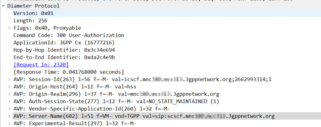
Using Kamailio as an Interrogating-CSCF, Kamailio was getting the S-CSCF details from the User-Authorization-Answer’s “Server-Name” (602) AVP.
The value was set to:
sip:scscf.mnc001.mcc001.3gppnetwork.org:5060
But the I-CSCF was only looking up A-Records for scscf.mnc001.mcc001.3gppnetwork.org, not using DNS-SRV.
The problem? The Server-Name I had configured as a full SIP URI in PyHSS including the port, meant that Kamailio only looks up the A-Record, and did not do a DNS-SRV lookup for the domain.
Dropping the port number saw all those delicious SRV records being queried.
Something to keep in mind if you use S-CSCF pooling with a Kamailio based I-CSCF, if you want to use SRV records for load balancing / traffic sharing, don’t include the port, and if instead you want it to go to the specified host found by an A-record, include the port.
So the other day I needed to extract the IP and Port parameters from an SDP body – Not the whole line mind, but the values themselves.
As with so many things in Kamailio, there’s a lot of ways to achieve an outcome, but here’s how I approached this problem.
Using the SDPops module we can get a particular line in the SDP, for example, we can get the media line with:
#Get SDP line starting with m= and put it into AVP $avp(mline)
sdp_get_line_startswith("$avp(mline)", "m=")
#Print value of $avp(mline)
xlog("m-line: $avp(mline)\n");
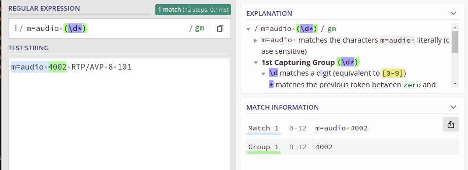
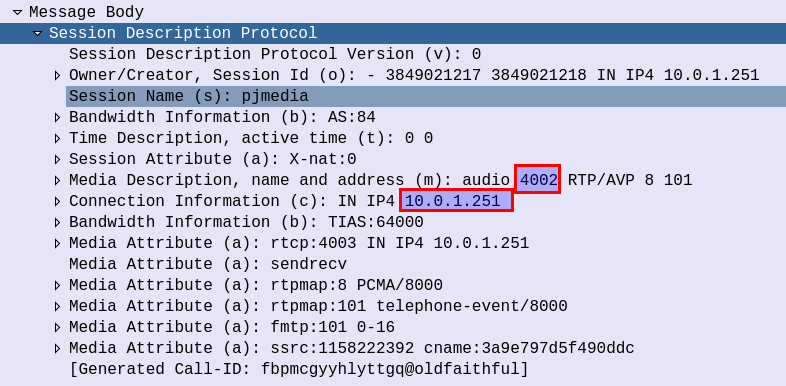
This gets us the line, but now we need to extract the data, in the example from the screenshot the M line has the value:
m=audio 4002 RTP/AVP 8 101
But we only want the port from the M line.
This is where I’ve used the Kamailio Dialplan module and regex to extract the port from this line.
With a fairly simple regex pattern, we can get a group match for the Port from the m= line.
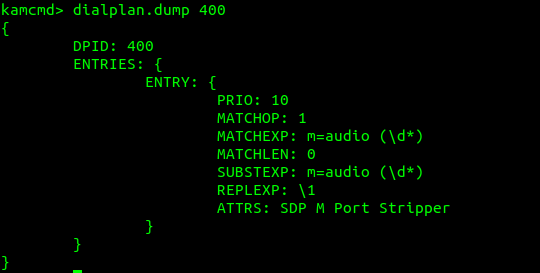
So I took this regular expression, and put it into the Kamailio Dialplan database with dialplan ID 400 for this example:
INSERT INTO `dialplan` VALUES (4,400,10,1,'m=audio (\\d*)',0,'m=audio (\\d*)','\\1','SDP M Port Stripper');
Now using Dialplan ID 400 we can translate an inputted m= SDP line, and get back the port used, so let’s put that into practice:
        if(sdp_get_line_startswith("$avp(mline)", "m=")) {
            xlog("m-line: $avp(mline)\n");
            xlog("raw: $avp(mline)");
            xlog("Extracting Port from Media Line");
            dp_translate("400", "$avp(mline)/$avp(m_port_b_leg)");
            xlog("Translated m_port_b_leg is: $avp(m_port_b_leg)");
        }
Now we have an AVP called $avp(m_port_b_leg) which contains the RTP Port from the SDP.
Now we’ve got a few other values we might want to get, such as the IP the RTP is to go to, etc, we can extract this in the same way, with Dialplans and store them as AVPs:
        #Print current SDP Values and store as Vars
        if(sdp_get_line_startswith("$avp(mline)", "m=")) {
            xlog("m-line: $avp(mline)\n");
            xlog("raw: $avp(mline)");
            xlog("Extracting Port from Media Line");
            dp_translate("400", "$avp(mline)/$avp(m_port_b_leg)");
            xlog("Translated m_port_b_leg is: $avp(m_port_b_leg)");
        }

        if(sdp_get_line_startswith("$avp(oline)", "o=")) {
            xlog("o-line: $avp(oline)\n");
            dp_translate("401", "$avp(oline)/$avp(o_line_port_1)");
            xlog("O Line Port 1: $avp(o_line_port_1)");
            dp_translate("402", "$avp(oline)/$avp(o_line_port_2)");
            xlog("O Line Port 2: $avp(o_line_port_2)");
            dp_translate("403", "$avp(oline)/$avp(o_ip_b_leg)");
            xlog("O IP: $avp(o_ip_b_leg)");
        }
And all the Regex you’ll need:
INSERT INTO `dialplan` VALUES
(4,400,10,1,'m=audio (\\d*)',0,'m=audio (\\d*)','\\1','SDP M Port Stripper'),
(5,401,10,1,'o=[^ ]* (\\d*) (\\d*) IN IP4 (\\d*.d*.\\d*.\\d*)',0,'o=[^ ]* (\\d*) (\\d*) IN IP4 (\\d*.d*.\\d*.\\d*)','\\1','O Port 1'),
(6,402,10,1,'o=[^ ]* (\\d*) (\\d*) IN IP4 (\\d*.d*.\\d*.\\d*)',0,'o=[^ ]* (\\d*) (\\d*) IN IP4 (\\d*.d*.\\d*.\\d*)','\\2','O Port 2'),
(7,403,10,1,'o=[^ ]* (\\d*) (\\d*) IN IP4 (\\d*.d*.\\d*.\\d*)',0,'o=[^ ]* (\\d*) (\\d*) IN IP4 (\\d*[.]\\d*[.]\\d*[.]\\d*)','\\3','O IP');
If you’ve ever received an SMS from your operator, and the sender was the Operator name for example, you may be left wondering how it’s done.
In IMS you’d think this could be quite simple – You’d set the From header to be the name rather than the MSISDN, but for most SMSoIP deployments, the From header is ignored and instead the c header inside the SMS body is used.
So how do we get it to show text?
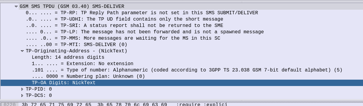
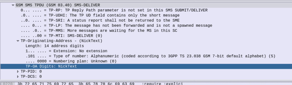
Well the TP-Originating address has the “Type of Number” (ToN) field which is typically set to International/National, but value 5 allows for the Digits to instead be alphanumeric characters.
GSM 7 bit encoding on the text in the TP-Originating Address digits and presto, you can send SMS to subscribers where the message shows as From an alphanumeric source.
On Android SMSs received from alphanumeric sources cannot be responded to (“no more “DO NOT REPLY TO THIS MESSAGE” at the end of each text), but on iOS devices you can respond, but if I send an SMS from “Nick” the reply from the subscriber using the iPhone will be sent to MSISDN 6425 (Nick on the telephone keypad).