So the issue was a head scratcher.
Everything was working on the IMS, then I go to bed, the next morning I fire up the test device and it just won’t authenticate to the IMS – The S-CSCF generated a 401 in response to the REGISTER, but the next REGISTER wouldn’t pass.
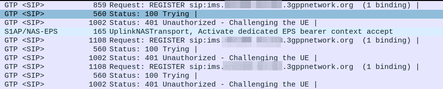
Wireshark just shows me this loop:
UE -> IMS: REGISTER
IMS -> UE: 401 Unauthorized (With Challenge)
UE -> IMS: REGISTER with response
IMS -> UE: 401 Unauthorized (With Challenge)
UE -> IMS: REGISTER with response
IMS -> UE: 401 Unauthorized (With Challenge)
UE -> IMS: REGISTER with response
IMS -> UE: 401 Unauthorized (With Challenge)
So what’s going on here?
IMS uses AKAv1-MD5 for Authentication, this is slightly different to the standard AKA auth used in cellular, but if you’re curious, we’ve covered by IMS Authentication and standard AKA based SIM Authentication in cellular networks before.
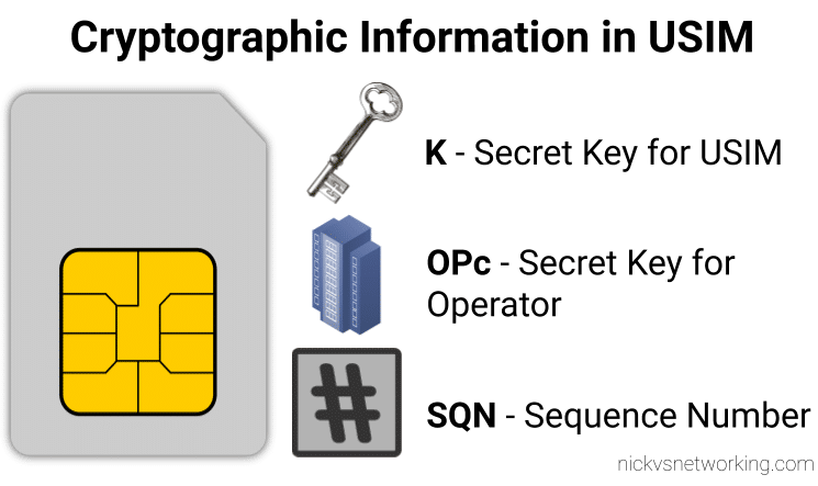
When we generate the vectors (for IMS auth and standard auth) one of the inputs to generate the vectors is the Sequence Number or SQN.
This SQN ticks over like an odometer for the number of times the SIM / HSS authentication process has been performed.
There is some leeway in the SQN – It may not always match between the SIM and the HSS and that’s to be expected.
When the MME sends an Authentication-Information-Request it can ask for multiple vectors so it’s got some in reserve for the next time the subscriber attaches, and that’s allowed.
But there are limits to how far out our SQN can be, and for good reason – One of the key purposes for the SQN is to protect against replay attacks, where the same vector is replayed to the UE. So the SQN on the HSS can be ahead of the SIM (within reason), but it can’t be behind – Odometers don’t go backwards.
So the issue was with the SQN on the SIM being out of Sync with the SQN in the IMS, how do we know this is the case, and how do we fix this?
Well there is a resync mechanism so the SIM can securely tell the HSS what the current SQN it is using, so the HSS can update it’s SQN.
When verifying the AUTN, the client may detect that the sequence numbers between the client and the server have fallen out of sync.
RFC 3110: HTTP Digest Authentication using AKA
In this case, the client produces a synchronization parameter AUTS, using the shared secret K and the client sequence number SQN.
The AUTS parameter is delivered to the network in the authentication response, and the authentication can be tried again based on authentication vectors generated with the synchronized sequence number.
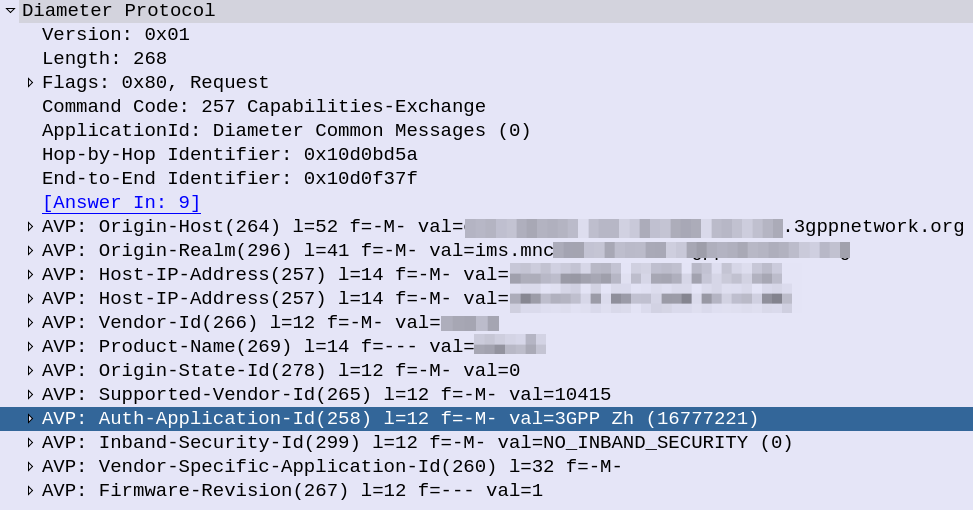
In our example we can tell the sub is out of sync as in our Multimedia Authentication Request we see the SIP-Authorization AVP, which contains the AUTS (client synchronization parameter) which the SIM generated and the UE sent back to the S-CSCF. Our HSS can use the AUTS value to determine the correct SQN.
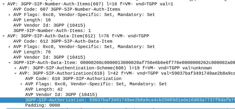
Note: The SIP-Authorization AVP actually contains both the RAND and the AUTN concatenated together, so in the above example the first 32 bytes are the AUTN value, and the last 32 bytes are the RAND value.
So the HSS gets the AUTS and from it is able to calculate the correct SQN to use.
Then the HSS just generates a new Multimedia Authentication Answer with a new vector using the correct SQN, sends it back to the IMS and presto, the UE can respond to the challenge normally.
This feature is now fully implemented in PyHSS for anyone wanting to have a play with it and see how it all works.
And that friends, is how we do SQN resync in IMS!