In our last post we dipped a toe into CGrateS.
We cheated a fair bit, to show something that worked, but it’s not something you’d probably want to use in real life, loading static CSV files gets us off the ground, but in reality we don’t want to manage a system through CSV files.
Instead, we’d want to use an API.
Fair warning – There is some familiarity expected with JSON and RESTful APIs required, we’ll use Python3 for our examples, but you can use any programing language you’re comfortable with, or even CURL commands.
So we’re going to start by clearing out all the data we setup in CGrateS using the cgr-loader tool from those imported CSVs:
redis-cli flushall
sudo mysql -Nse 'show tables' cgrates | while read table; do sudo mysql -e "truncate table $table" cgrates; done
cgr-migrator -exec=*set_versions -stordb_passwd=CGRateS.org
sudo systemctl restart cgrates
So what have we just done?
Well, we’ve just cleared all the data in CGrateS.
We’re starting with a blank slate.
In this post, we’re going to define some Destinations, some Rates to charge and then some DestinationRates to link each Destination to a Rate.
But this time we’ll be doing this through the CGrateS API.
Introduction to the CGrateS API
CGrateS is all API driven – so let’s get acquainted with this API.
I’ve written a simple Python wrapper you can find here that will make talking to CGRateS a little easier, so let’s take it for a spin and get the Destinations that are loaded into our system:
import cgrateshttpapi
CGRateS_Obj = cgrateshttpapi.CGRateS('172.16.41.133', 2080) #Replace this IP with the IP Address of your CGrateS instance...

destinations = CGRateS_Obj.SendData({'method':'ApierV1.GetTPDestinationIDs','params':[{"TPid":"cgrates.org"}]})['result']

#Pretty print the result:
print("Destinations: ")
pprint.pprint(destinations)
All going well you’ll see something like this back:
Initializing with host 172.16.41.133 on port 2080
Sending Request with Body:
{'method': 'ApierV2.Ping', 'params': [{'Tenant': 'cgrates.org'}]}
Sending Request with Body:
{'method': 'ApierV2.GetTPDestinationIDs', 'params': [{"TPid":"cgrates.org"}]}
Destinations from CGRates: []
So what did we just do?
Well, we sent a JSON formatted string to the CGRateS API at 172.16.41.133 on port 2080 – You’ll obviously need to change this to the IP of your CGrateS instance.
In the JSON body we sent we asked for all the Destinations using the ApierV1.GetTPDestinationIDs method, for the TPid ‘cgrates.org’,
And it looks like no destinations were sent back, so let’s change that!
Note: There’s API Version 1 and API Version 2, not all functions exist in both (at least not in the docs) so you have to use a mix.
Adding Destinations via the API
So now we’ve got our API setup, let’s see if we can add a destination!
To add a destination, we’ll need to go to the API guide and find the API call to add a destination – in our case the API call is ApierV2.SetTPDestination and will look like this:
{'method': 'ApierV2.SetTPDestination', 'params': [
    {"TPid": "cgrates.org", "ID": "Dest_AU_Mobile",
        "Prefixes": ["614"]}]}
So we’re creating a Destination named Dest_AU_Mobile and Prefix 614 will match this destination.
Note: I like to prefix all my Destinations with Dest_, all my rates with Rate_, etc, so it makes it easy when reading what’s going on what object is what, you may wish to do the same!
So we’ll use the Python code we had before to list the destinations, but this time, we’ll use the ApierV2.SetTPDestination API call to add a destination before listing them, let’s take a look:
import cgrateshttpapi
import pprint
import sys
CGRateS_Obj = cgrateshttpapi.CGRateS('172.16.41.133', 2080)

CGRateS_Obj.SendData({'method':'ApierV2.SetTPDestination','params':[{"TPid":"cgrates.org","ID":"Dest_AU_Mobile","Prefixes":["614"]}]})

destinations = CGRateS_Obj.SendData({'method':'ApierV1.GetTPDestinationIDs','params':[{"TPid":"cgrates.org"}]})['result']
print("Destinations: ")
pprint.pprint(destinations)
print("\n\n\n")
Now if you run the code you’ll see something like this:
Initializing with host 172.16.41.133 on port 2080
Sending Request with Body:

Sending Request with Body:
{'method': 'ApierV2.SetTPDestination', 'params': [{'TPid': 'cgrates.org', 'ID': 'Dest_AU_Mobile', 'Prefixes': ['614']}]}

{'method': 'ApierV1.GetTPDestinationIDs', 'params': [{'TPid': 'cgrates.org'}]}
Destinations:
['Dest_AU_Mobile']
Boom! There’s our added destination, le’s add a few more using the same process, so we’ve got a few other destinations defined:
CGRateS_Obj = cgrateshttpapi.CGRateS('172.16.41.133', 2080)

CGRateS_Obj.SendData({'method':'ApierV2.SetTPDestination','params':[{"TPid":"cgrates.org","ID":"Dest_AU_Fixed","Prefixes":["612", "613", "617", "618"]}]})
CGRateS_Obj.SendData({'method':'ApierV2.SetTPDestination','params':[{"TPid":"cgrates.org","ID":"Dest_AU_Mobile","Prefixes":["614"]}]})
CGRateS_Obj.SendData({'method':'ApierV2.SetTPDestination','params':[{"TPid":"cgrates.org","ID":"Dest_AU_TollFree","Prefixes":["6113", "6118"]}]})


print("Destinations: ")
for destination in destinations:
    destination = CGRateS_Obj.SendData({'method':'ApierV1.GetTPDestination','params':[{"TPid":"cgrates.org", "ID" : str(destination)}]})['result']
    pprint.pprint(destination)
print("\n\n\n")
sys.exit()
After adding some prettier printing and looping through all the destinations, here’s what your destinations should look like:
OrderedDict([('TPid', 'cgrates.org'),
             ('ID', 'Dest_AU_Fixed'),
             ('Prefixes', ['612', '613', '617', '618'])])

OrderedDict([('TPid', 'cgrates.org'),
             ('ID', 'Dest_AU_Mobile'),
             ('Prefixes', ['614'])])

OrderedDict([('TPid', 'cgrates.org'),
             ('ID', 'Dest_AU_TollFree'),
             ('Prefixes', ['6113', '6118'])])
Notice for AU Fixed, we defined multiple prefixes under the same Destination? Just as items in the list.
So we’ve created a bunch of Destinations, like so:
| Name | Prefix |
| Dest_AU_TollFree | 6113 & 6118 |
| Dest_AU_Fixed | 612, 613, 617 & 618 |
| Dest_AU_Mobile | 614 |
Next let’s create some rates which we can then associate with these destinations.
Adding Rates via the API
So to begin with let’s see if we’ve got any rates defined, we can do this with another API call, this time the ApierV1.GetTPRateIds call.
{"method":"ApierV1.GetTPRateIds","params":[{"TPid":"cgrates.org"}]}
And at the moment that returns no results, so let’s add some rates.
For this we’ll use the ApierV1.SetTPRate function:
{"method":"ApierV1.SetTPRate","params":[{"ID":"Rate_AU_Mobile_Rate_1","TPid":"cgrates.org","RateSlots":[{"ConnectFee":0,"Rate":22,"RateUnit":"60s","RateIncrement":"60s","GroupIntervalStart":"0s"}]}],"id":1}
If we post this to the CGR engine, we’ll create a rate, named Rate_AU_Mobile_Rate_1 that bills 22 cents per minute, charged every 60 seconds.
Let’s add a few rates:
CGRateS_Obj.SendData({"method":"ApierV1.SetTPRate","params":[{"ID":"Rate_AU_Mobile_Rate_1","TPid":"cgrates.org","RateSlots":[{"ConnectFee":0,"Rate":22,"RateUnit":"60s","RateIncrement":"60s","GroupIntervalStart":"0s"}]}],"id":1})
CGRateS_Obj.SendData({"method":"ApierV1.SetTPRate","params":[{"ID":"Rate_AU_Fixed_Rate_1","TPid":"cgrates.org","RateSlots":[{"ConnectFee":0,"Rate":14,"RateUnit":"60s","RateIncrement":"60s","GroupIntervalStart":"0s"}]}],"id":1})
CGRateS_Obj.SendData({"method":"ApierV1.SetTPRate","params":[{"ID":"Rate_AU_Toll_Free_Rate_1","TPid":"cgrates.org","RateSlots":[{"ConnectFee":25,"Rate":0,"RateUnit":"60s","RateIncrement":"60s","GroupIntervalStart":"0s"}]}],"id":1})

TPRateIds = CGRateS_Obj.SendData({"method":"ApierV1.GetTPRateIds","params":[{"TPid":"cgrates.org"}]})['result']
print(TPRateIds)
for TPRateId in TPRateIds:
    print("\tRate: " + str(TPRateId))
All going well, when you add the above, we’ll have added 3 new rates:
| Rate Name | Cost | |
| Rate_AU_Fixed_Rate_1 | 14c per minute charged every 60s | |
| Rate_AU_Mobile_Rate_1 | 22c per minute charged every 60s | |
| Rate_AU_Toll_Free_Rate_1 | 25c connection, untimed |
Linking Rates to Destinations
So now with Destinations defined, and Rates defined, it’s time to link these two together!
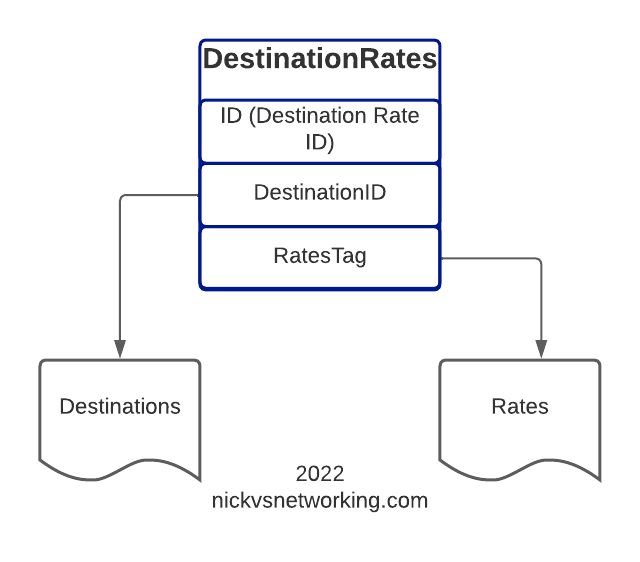
Destination Rates link our Destinations and Route rates, this decoupling means that we can have one Rate shared by multiple Destinations if we wanted, and makes things very flexible.
For this example, we’re going to map the Destinations to rates like this:
| DestinationRate Name | Destination Name | Rate Name |
| DestinationRate_AU | Dest_AU_Fixed | Rate_AU_Fixed_Rate_1 |
| DestinationRate_AU | Dest_AU_Mobile | Rate_AU_Mobile_Rate_1 |
| DestinationRate_AU | Dest_AU_TollFree | Rate_AU_Toll_Free_Rate_1 |
So let’s go about making this link in CGrateS, for this we’ll use the ApierV1.SetTPDestinationRate method to add the DestinationRate, and the ApierV1.GetTPDestinationRateIds to get the list of them.
CGRateS_Obj.SendData({"method": "ApierV1.SetTPDestinationRate", "params": \
    [{"ID": "DestinationRate_AU", "TPid": "cgrates.org", "DestinationRates": \
        [ {"DestinationId": "Dest_AU_Fixed", "RateId": "Rate_AU_Fixed_Rate_1", "Rate": None, "RoundingMethod": "*up", "RoundingDecimals": 4, "MaxCost": 0, "MaxCostStrategy": ""} ]\
    }]})

TPDestinationRates = CGRateS_Obj.SendData({"jsonrpc":"2.0","method":"ApierV1.GetTPDestinationRateIds","params":[{"TPid":"cgrates.org"}]})['result']
for TPDestinationRate in TPDestinationRates:
    pprint.pprint(TPDestinationRate)
All going well, you’ll see the new DestinationRate we added.
Here’s a good chance to show how we can add multiple bits of data in one API call, we can tweak the ApierV1.SetTPDestinationRate method and include all the DestinationRates we need in one API call:
CGRateS_Obj.SendData({"method": "ApierV1.SetTPDestinationRate", "params": [
        {"ID": "DestinationRate_AU", "TPid": "cgrates.org", "DestinationRates": [ \
            {"DestinationId": "Dest_AU_Fixed", "RateId": "Rate_AU_Fixed_Rate_1", "Rate": None, "RoundingMethod": "*up", "RoundingDecimals": 4, "MaxCost": 0, "MaxCostStrategy": ""},\
            {"DestinationId": "Dest_AU_Mobile", "RateId": "Rate_AU_Mobile_Rate_1", "Rate": None, "RoundingMethod": "*up", "RoundingDecimals": 4, "MaxCost": 0, "MaxCostStrategy": ""}, \
            {"DestinationId": "Dest_AU_TollFree", "RateId": "Rate_AU_Toll_Free_Rate_1", "Rate": None, "RoundingMethod": "*up", "RoundingDecimals": 4, "MaxCost": 0, "MaxCostStrategy": ""}\
     ]},
    ]})
As we’ve only created one DestinationRate, let’s take a look at the detail:
TPDestinationRate = CGRateS_Obj.SendData({"jsonrpc":"2.0","method":"ApierV1.GetTPDestinationRate","params":[{"ID":"DestinationRate_AU","TPid":"cgrates.org"}],"id":1})
pprint.pprint(TPDestinationRate)
Phew, okay, if you made it this far, congratulations.
So where we stand now is we’ve created Rates, Destinations and tied the two together.
I’ve put a copy of all the Python code on GitHub here, in case you’re having issues you can work with that.
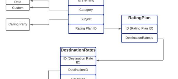
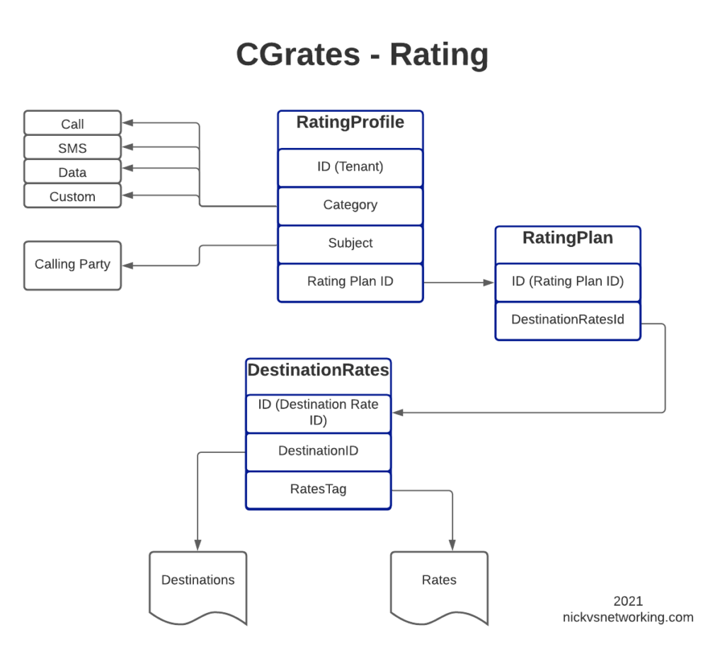
In our next post, we’ll keep working our way up this diagram, by creating RatingPlans and RatingProfiles to reference the DestinationRate we just created.
Other posts in the CGrateS in Baby Steps series:
- CGrateS Part 1 – Basics of CGrateS
- CGrateS in Baby Steps – Part 2 – Adding Rates and Destinations through the API
- CGrateS in Baby Steps – Part 3 – RatingProfiles & RatingPlans
- CGrateS in Baby Steps – Part 4 – Rating Calls
- CGrateS in Baby Steps – Part 5 – Events, Agents & Subsystems
- All the other posts tagged with CGrateS including SessionS, Attributes, Accounts & Balances, Actions & Action Plans, ActionTriggers, FilterS, StatS, Event Reader, CDR Export.