A totally complete history and not just something I learned from a fellow phone nerd who’s been around a lot longer than me...
In the early days of telephony voice calls were made by signaling to an operator who would connect your call.
Around the turn of the century the first “automatic” exchanges began to open. This meant that a subscriber could complete their own call, by directly dialing the digits of the party the want to speak to, and getting through, without a human operator “plugging up” the call.
The first type of switches used to provide “automatic” exchange capability were Strowger type switches, they translated the pulses from a rotary dial phone into physical movements on a switch to find and select the line you want.
As it happens I have one of these old switches, here’s what happens when you let go of the dial.
People who were born before touch tone phones can tell you about how you can dial a phone number without using the dial at all. By mashing the hook switch really quickly. If you want to dial a 3 you mash the hook switch 3 times, then wait a second, then to dial a 5 smash the hook switch 5 times, etc, etc.
A quirk of this is that higher numbers, are harder to dial, you just need one pulse of the hook switch in a second to dial a 1, but you need 10 pulses to dial a 0. This means a phone dial that’s running too slow can dial the lower digits, but not the higher digits, as it can’t pulse out the required number of pulses is the time allotted (a smidge over 1 second per digit).
Initially exchanges only connected local calls, but with the introduction of Subscriber Trunk Dialing (STD), subscribers could call from one exchange to another without an operator.
This led to national dialing plans being developed, ensuring uniqueness of numbers across the whole of the phone network, and where possible, lower numbers were used, Australia for example has area codes 02, 03, 07 and 08 (with the majority of the population living in the 02 and 03 area codes).
Now imagine you’re the government owned phone company, tasked with creating a single number for emergency services, 123, 111, etc, etc, are all taken up, as these are the most reliable numbers to dial and were used long ago.
Instead you go to the other end, the UK with 999 and Australia with 000 (911 is a different kettle of fish).
Except in New Zealand.
111 was specifically chosen to be similar to Britain’s 999 service, but NZ has some odd peculiarities.
The NZ dials are identical to the standard dial except for the finger plate label.
With pulse dialing, New Zealand telephones pulse “in reverse” to the rest of the world. Dialing 0 on a phone in the rest of the world, sent ten pulses down the line. But dialing a 0 on a phone in NZ sent one pulse down the line. The same for all the other numbers. The phones weren’t different – Just the labels.
Hence the reason why ‘Emergency’ services were on 111 in NZ (but actually pulsed 999) as the exchanges originated in those days from the UK where 999 was (and still is 999).
In the early years of 111, the telephone equipment was based on British Post Office equipment, except for this unusual orientation. Therefore, dialing 111 on a New Zealand telephone sent three sets of nine pulses to the exchange, exactly the same as the UK’s 999.
PyHSS is our open source Home Subscriber Server, it’s written in Python, has a variety of different backends, and is highly perforate (We benchmark to 10K transactions per second) and infinitely scaleable.
In this post I’ll cover the basics of setting up PyHSS in your enviroment and getting some Diameter peers connected.
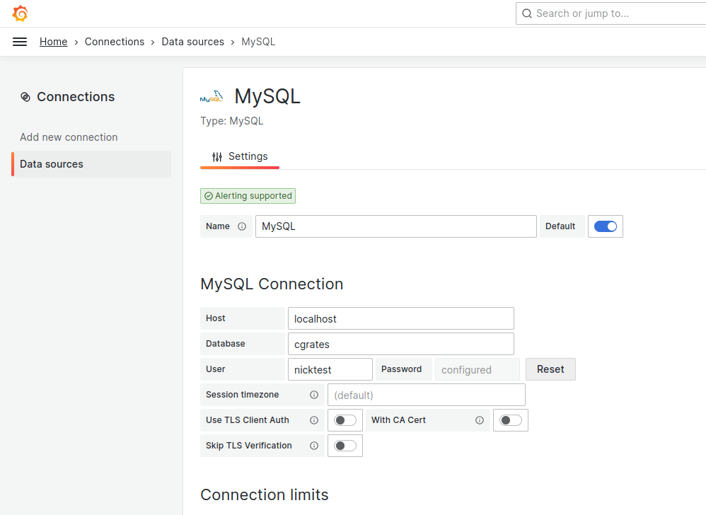
For starters, we’ll need a database (We’ll use MySQL for this demo) and an account on that database for a MySQL user.
So let’s get that rolling (I’m using Ubuntu 24.04):
sudo apt update
sudo apt install mysql-server
Next we’ll create the MySQL user for PyHSS to use:
CREATE USER 'pyhss_user'@'%' IDENTIFIED BY 'pyhss_password';
GRANT ALL PRIVILEGES ON *.* TO 'pyhss_user'@'%' WITH GRANT OPTION;
FLUSH PRIVILEGES;
We’ll also need Redis as well (PyHSS uses Redis for inter-service communications and for caching), so go ahead an install that for your distro:
sudo apt install redis-server
So that’s our prerequisites sorted, let’s clone the PyHSS repo:
And install the requirements with pip from the PyHSS repo:
pip3 install -r requirements.txt
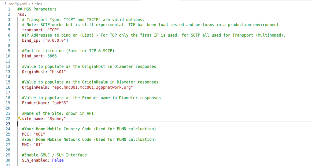
Next we’ll need to configure PyHSS, for that we update the config file (config.yaml) with the settings we want to use.
We’ll start by setting the bind_ip to a list of IPs you want to listen on, and your transport – We can use either TCP or SCTP.
For Diameter, we will set OriginHost and OriginRealm to match the Diameter hostname you want to use for this peer, and the Realm of your Diameter network.
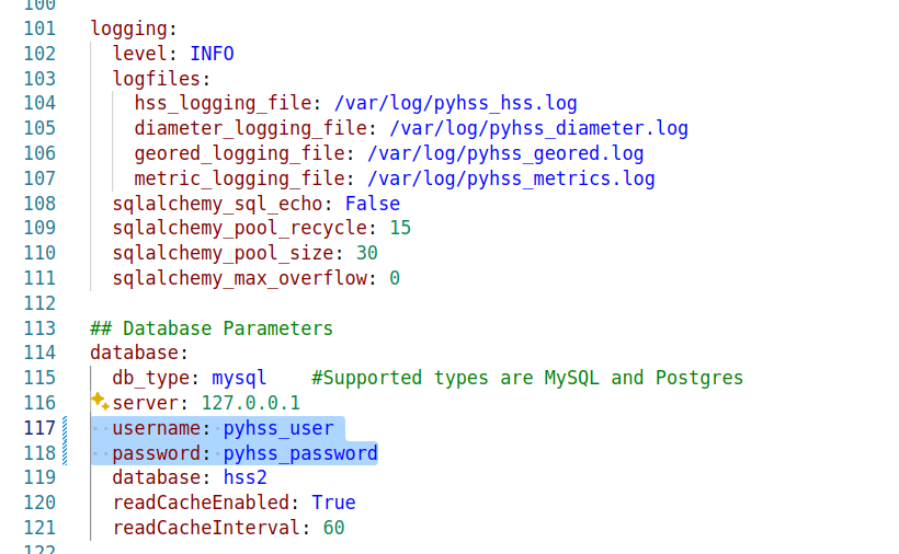
Lastly we’ll need to set the database parameters, updating the database: section to populate your credentials, setting your username and password and the database to match your SQL installation we setup at the start.
With that done, we can start PyHSS, which we do using systemctl.
Because there’s multiple microservices that make up PyHSS, there’s multiple systemctl files use to run PyHSS as a service, they’re all in the /systemd folder.
Like a lot of companies, we’re moving away from VMware, and in our case, shifting to Proxmox.
But that doesn’t mean we can get entirely away from VMware, but more that it’s not our hypervisor of choice anymore, and this means shifting our dev environments and lab off VMware to Proxmox first.
So today I sat down to try and shift everything to Proxmox, while keeping the VMware based VMs accessible until they can slowly die of bitrot.
A sane person would probably utilize Proxmox’s fancy new tool for migrating VMs from VMware to Proxmox, and it’s great, but in our case at least, it required logging into each VM and remapping NICs, etc, which is tricky on boxes I don’t have access to – Plus we need to keep some VMware capability for testing / labbing stuff up.
So I decided into install Proxmox onto the bare metal servers, and then create a VMware virtual machine inside the Proxmox stack, to host a VMware ESXi instance.
I started off inside VMware (Before installing any Proxmox) by moving all the VMs onto a single physical disk, which I then removed from the server, so as to not accidentally format the one disk I didn’t want to format.
Next I nuked the server and setup the new stack with Proxmox, which is a doddle, and not something I’ll cover.
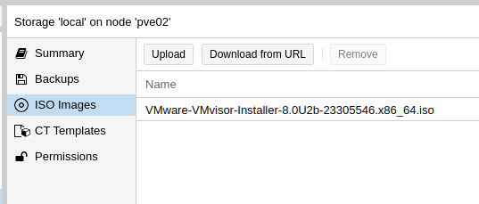
Then I loaded a VMware ISO into Proxmox and started setting up the VM.
Now, nested virtualization is a real pain in the behind.
VMware doesn’t like not being run on bare metal, and it took me a good long amount of time to find the hardware config that I could setup in Proxmox that VMware would accept.
Create the VM in the Web UI; I found using a SATA drive worked while SCSI failed, so create a SATA based LVM image to use, and mount the datastore ISO.
Then edit /etc/pve/qemu-server/your_id.conf and replace the netX, args, boot and ostype to match the below:
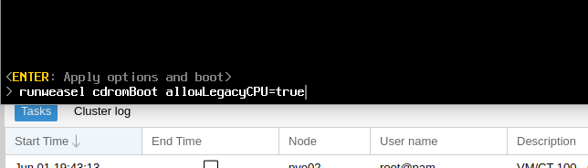
Now you can go and start the VM, but once you’ve got the VMware splash screen, you’ll need to press Shift + O to enter the boot options.
At the runweasle cdromBoot after it add allowLegacyCPU=true– This will allow ESXi to use our (virtual) CPU.
Next up you’ll install VMware ESXi just like you’ve probably done 100 times before (is this the last time?), and once it’s done installing, power off, we’ll have to make few changes to the VM definition file.
Then after install we need to change the boot order, by updating:
boot: order=sata0
And unmount the ISO:
ide2: none,media=cdrom
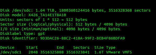
Now remember how I’d pulled the hard disk containing all the VMware VMs out so I couldn’t break it? Well, don’t drop that, because now we’re going to map that physical drive into the VM for VMware, so I can boot all those VMs.
I plugged in the drive and I used this to find the drive I’d just inserted:
fdisk -l
Which showed the drive I’d just added last, with it’s VMware file system.
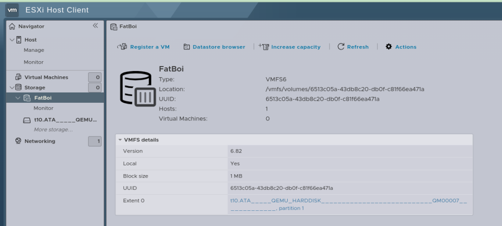
So next we need to map this through the VM we just created inside Proxmox, so VMware inside Proxmox can access the VMware file system on the disk filled with all our old VMware VMs.
VM. VM. VM. The word has lost all meaning to me at this stage.
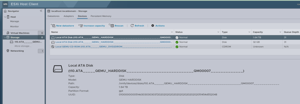
We can see the mount point of our physical disk; in our case is /dev/sdc so that’s what we’ll pass through to the VM.
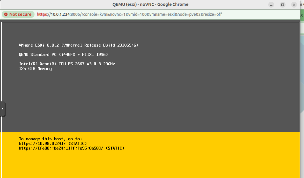
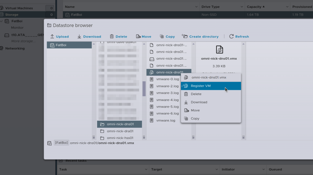
And now, if everything has gone well, after logging into the Web UI, you’ll see this:
Then the last step is going to be re-registering all the VMs, you can do this by hand, by selecting the .vmx file and adding it.
Alternately, if you’re lazy like me, I wrote a little script to do the same thing:
[root@localhost:~] cat load_vms3.sh


#!/bin/bash

# Datastore name
DATASTORE="FatBoi/"

# Log file to store the output
LOG_FILE="/var/log/register_vms.log"

# Clear the log file
> $LOG_FILE

echo "Starting VM registration process on datastore: $DATASTORE" | tee -a $LOG_FILE

# Check if datastore directory exists
if [ ! -d "/vmfs/volumes/$DATASTORE" ]; then
    echo "Datastore $DATASTORE does not exist!" | tee -a $LOG_FILE
    exit 1
fi

# Find all .vmx files in the datastore and register them
find /vmfs/volumes/$DATASTORE -type f -name "*.vmx" | while read VMX_PATH; do
    echo "Registering VM: $VMX_PATH" | tee -a $LOG_FILE
    vim-cmd solo/registervm "$VMX_PATH" | tee -a $LOG_FILE
done

echo "VM registration process completed." | tee -a $LOG_FILE

[root@localhost:~] sh load_vms3.sh
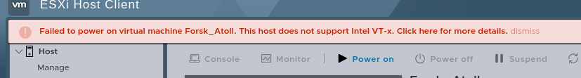
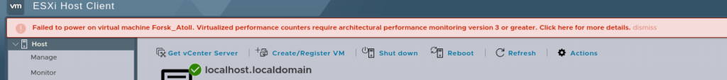
Now with all your VMs loaded, you should almost be ready to roll and power them all back on.
But before we reboot the Hypervisor (Proxmox) we’ll have to reboot the VMware hypervisor too, because here’s something else to make you punch the screen:
Luckily we can fix this one globaly.
SSH into the VMware box, edit /etc/vmware/config.xml file and add:
vhv.enable = "FALSE"
Which will disable the performance counters.
Now power off the VMware VM, and reboot the Proxmox hypervisor, when it powers on again, Proxmox will allow nested virtualization, and when you power back on the VMware VM, you’ll have performance counters disabled, and then, you will be done.
Yeah, not a great use of my Saturday, but here we are…
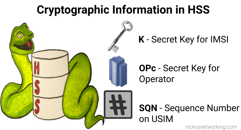
The Equipment Identity Register (EIR) is a pretty handy function in 3GPP networks.
Via the Diameter based S13 interface, the MME, is able to query the EIR to ask if a given IMEI & IMSI combination should be allowed to attach.
This allows stolen / grey market / unauthorized devices (IMEIs) to be rejected from the network, the EIR can have a list of “bad” IMEIs that if seen will reject the request.
It also allows us to lock a SIM (IMSI) to a given device (IMEI) or type of device – We can use this for say a Fixed Wireless service, to lock the SIMs (IMSIs) to a range of modems (IMEI Prefixes).
Lastly it gives us insight and analytics into the devices used on the network, by mapping the IMEI to a device, we can say that IMEI 1234567890 is an Apple iPhone 12 Pro Max, or a Nokia Fastmile 5G-24W-A.
PyHSS supports all these capabilities, so let’s have a look at how we’d manage / access them.
Setting up EIR Rules
These rules are set via the RESTful API in PyHSS.
The Equipment Identity Register built into PyHSS supports matching in one of two modes, set by regex_mode.
In Exact Mode (regex_mode: 0) matches are based on an exact matching IMEI, and matching the IMSI if set (If IMSI is set to nothing (”), then only the IMEI is evaluated).
Exact Mode is suited for IMEI/IMSI locking, to ensure a SIM is locked to a particular device, or to blacklist stolen devices.
Regex Mode (regex_mode: 1) matches based on Regex, this is suited for whitelisting IMEI prefixes for say, specific validated vendors.
The match_response_code maps to the Equipment-Status AVP output, so specified values are:
0 : ‘Whitelist’
1: ‘Blacklist’
2: ‘Greylist’
Some end to end examples of this provisioned into the API:
If the IMEI starts with 777 and the IMSI is 1234123412341234 then return 2 (Greylist).
No Match Behaviour
If there is no match from the backend, then the config parameter no_match_response dictates the response code returned (Blacklist/Whitelist/Greylist).
Mapping Type Allocation Codes (TACs) to IMEIs
There are several data feeds of the Type Allocation Codes (TACs) which map a given IMEI prefix to a model number.
TAC database extract
Unfortunately, this data is not freely available, so we can’t bundle it with PyHSS, but if you have the IMEI Database, you can load it into PyHSS using Redis, to allow us to report on this data.
In your config.yaml you’ll just need to set the tac_database parameter, which will read the data on startup.
PyHSS YAML Config extract
Triggering on SIM Swap
If we keep track of the current IMSI/IMEI combination used for each SIM/Device, we can get notified every time it changes.
You might want to use this to trigger OTA provisioning or clear old data in your IMS.
For that we can use the sim_swap_notify_webhook in the config to send a HTTP POST to a given endpoint to inform it that a SIM is now in a different device.
We also have to have imsi_imei_logging set to true in the Config in order to log the history.
Reporting on IMEIs
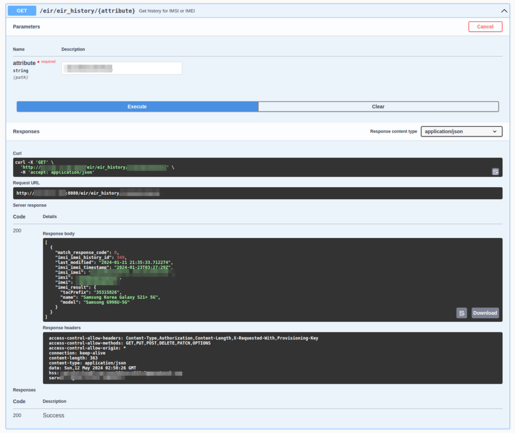
We can also log/capture historical data about IMSI/IMEI combinations.
We use this from a customer support perspective to be able to see if a customer has recently changed phones, so if they call support, our staff can ask the customer about it to help troubleshoot.
“I can see you were connected previously on a Samsung Galaxy S22, but now you’re using a Nokia 3310, did the issues happen before you moved phones?”
This is super handy.
We can get a general log of IMSI vs IMEI like this:
Feed of IMSI vs IMEI along with a timestamp and the response that was sent back
But what’s more useful is searching for a IMSI or an IMEI and then getting back a full list of devices / SIMs that have been used.
Searching for an IMSI I can see it’s only ever been used in this Samsung Galaxy
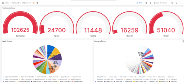
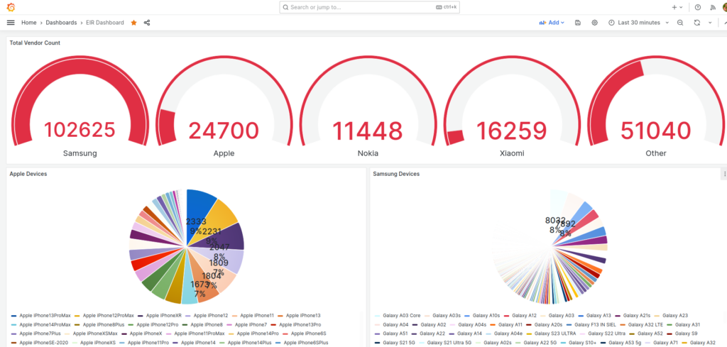
Lastly via Grafana we export all this data, which allows us to visualize this data and build dashboards showing the devices on the network.
Visualizing EIR Data in Grafana
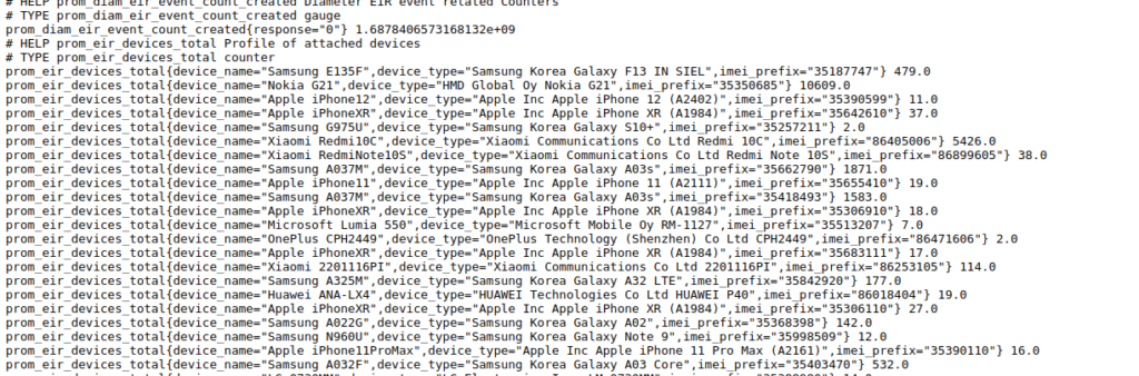
PyHSS includes a Promethues exporter, when it comes to prom_eir_devices_total it lists each seen Type Allocation Code / UE in the network, along with the number we’ve seen of each.
Raw it looks like this:
But visualized in Grafana we can get a dashboard to give us a breakdown per vendor:
Hello Nick, thank you for the article. What is the use of the OPc key to be derived from OP key ? Why can’t it just be a random key like Ki ?
It’s a super good question, and something I see a lot of operators get “wrong” from a security best practices perspective.
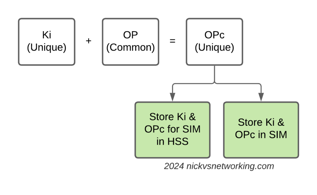
Refresher on OP vs OPc Keys
The “OP Key” is the “operator” key, and was (historically) common for an operator.
This meant all SIMs in the network had a common OP Key, and each SIM had a unique Ki/K key.
The SIM knew both, and the HSS only needed to know what the Ki was for the SIM, as they shared a common OP Key (Generally you associate an index which translates to the OP Key for that batch of SIMs but you get the idea).
But having common key material is probably not the best idea – I’m sure there was probably some reason why using a common key across all the SIMs seemed like a good option, and the K / Ki key has always been unique, so there was one unique key per SIM, but previously, OP was common.
Over time, the issues with this became clear, so the OPc key was introduced. OPc is derived from mushing the K & OP key together. This means we don’t need to expose / store the original OP key in the SIM or the HSS just the derived OPc key output.
This adds additional security, if the Ki for a SIM were to be exposed along with the OP for that operator, that’s half the entropy lost. Whereas by storing the Ki and OPc you limit the blast radius if say a single SIMs data was exposed, to only the data for that particular SIM.
This is how most operators achieve this today; there is still a common OP Key, locked away in a vault alongside the recipe for Coca-cola and the moon landing set.
But his OP Key is no longer written to the SIMs or stored in the HSS.
Instead, during the personalization process (The bit in manufacturing where SIMs get the unique data written to them (The IMSI & keys)) a derived OPc key is written to the card itself, and to the output files the operator then loads into their HSS/HLR/AuC.
This is not my preferred method for handling key material however, today we get our SIM manufacturers to randomize the OP key for every card and then derive an OPc from that.
This means we have two unique keys for each SIM, and even if the Ki and OP were to become exposed for a SIM, there is nothing common between that SIM, and the other SIMs in the network.
Do we want our Ki to leak? No. Do we want an OP Key to leak? No. But if we’ve got unique keys for everything we minimize the blast radius if something were to happen – Just minimizes the risk.
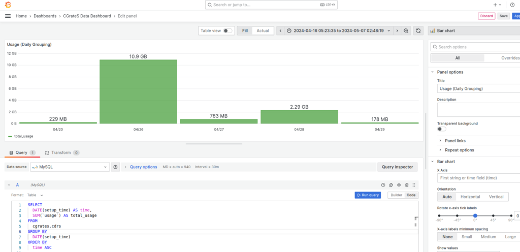
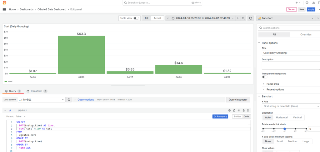
After we setup CgrateS the next thing we’d generally want to do would be to rate some traffic.
Of course, that could be realtime traffic, from Diameter, Radius, Kamailio, FreeSWITCH, Asterisk or whatever your case may be, but it could just as easily be CSV files, records from a database or a text file.
We’re going to be rating CDRs from simple CSV files with the date of the event, calling party, called party, and talk time, but of course your CDR exports will have a different format, and that’s to be expected – we tailor the Event Reader Service to match the format of the files we need.
The Event Reader Service, like everything inside CgrateS, is modular. ERS is a module we load that parses files using the rules we define, and creates Events that CgrateS can process and charge for, based on the rules we define.
But before I can tell you that story, I have to tell you this story…
Nick’s imaginary CSV factory
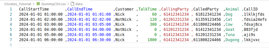
In the repo I’ve added a DummyCSV.csv, it’s (as you might have guessed) a CSV file.
This CSV file is like a million other CSV formats out there – We’ve got a CSV file with Start Time, End Time, Customer, Talk Time, Calling Party, Called Party, Animal (for reasons) and CallID to uniquely identify this CDR.
Protip: The Rainbow CSV VScode extension makes viewing/editing/querying CSV files in VScode much easier.
Call Start Time
Row 0
Call End Time
Row 1
Customer
Row 2
Talk Time
Row 3
Calling Party
Row 4
Called Party
Row 5
Animal
Row 6
CallID
Row 7
File Format
Next we need to feed this into CGrateS, and for that we’ll be using the Event Reporter Service.
JSON config files don’t make for riveting blog posts, but you’ve made it this far, so let’s power through.
ERS is setup in CGrateS’ JSON config file, where we’ll need to define one or more readers which are the the logic we define inside CGrateS to tell it what fields are what, where to find the files we need to import, and set all the parameters for the imports.
This means if we have a CSV file type we get from one of our suppliers with CDRs in it, we’d define a reader to parse that type of file. Likewise, if we’ve got a CSV of SMS traffic out of our SMSc, we’d need to define another reader to parse the CDRs in that format – Generally we’ll do a Reader for each file type we want to parse.
So let’s define a reader for this CSV spec we’ve just defined:
"ers": {
	"enabled": true,
	"readers": [
		{
			"id": "blog_example_csv_parser",
			"enabled": true,
			"run_delay":  "-1",
			"type": "*file_csv",
			"opts": {
				"csvFieldSeparator":",",
				"csvLazyQuotes": true,
				//csvLazyQuotes Counts the row length and if does not match this value declares an error
				//-1 means to look at the first row and use that as the row length
				"csvRowLength": -1
			},
			"source_path": "/var/spool/cgrates/blog_example_csv_parser/in",
			"processed_path": "/var/spool/cgrates/blog_example_csv_parser/out",
			"concurrent_requests": 1024,	//How many files to process at the same time
			"flags": [
				"*cdrs",
				"*log"
			],
			"tenant": "cgrates.org",
			"filters": [
				"*string:~*req.2:Nick", //Only process CDRs where Customer column == "Nick"
			],
			"fields":[]
}]}
This should hopefully be relatively simple (I’ve commented it as best I can).
The ID of the ERS object is just the name of this reader – you can name it anything you like, keeping in mind we can have multiple readers defined for different file formats we may want to read, and setting the ID just helps to differentiate them.
The run_delay of -1 means ERS will run as soon as a file is moved into the source_path directory, and the type is a CSV file – Note that’s moved not copied. We’ve got to move the file, not just copy it, as CGrateS waits for the inode notify.
In the opts section we set the specifics for the CSV we’re reading, field separator if how we’re separating the values in our CSV, and in our case, we’re using commas to delineate the fields, but if you were using a file using semicolons or another delineator, you’d adjust this.
Lastly we’ve got the paths, the source path is where we’ll need to move the files to get processed into, and the processed_path is where the processed files will end up.
For now I’ve set the flags to *log and *cdrs – By calling log we’ll make our lives a bit easier for debugging, and CDRs will send the event to the CDRs module to generate a rated CDR in CGrateS, which we could then use to bill a customer, a supplier, etc, and access via the API or exporting using Event Exporter Service.
Lastly under FilterS we’re able to define the filters that should define if we should process a row or not. You don’t know how much you need this feature until you need this feature. The filter rule I’ve included will only process lines where the Customer field in the CSV (row #2) is equal to “Nick”. You could use this to also filter only calls that have been answered, only calls to off-net, etc, etc – FilterS needs a blog post all on it’s own (and if you’re reading this in the future I may have already written one).
Alright, so far so good, we’ve just defined the metadata we need to do to read the file, but now how do we actually get down to parsing the lines in the file?
Well, that’s where the data in Fields: [] comes in.
If you’ve been following along the CgrateS in baby steps series, you’ll have rated a CDR using the API, that looked something like this:
ERS is going to use the same API to rate a CDR, calling more-or-less the same API, so we’re going to set the parameters that go into this from the CSV contents inside the fields:
			"fields":[

				//Type of Record (Voice)
				{"tag": "ToR", "path": "*cgreq.ToR", "type": "*constant", "value": "*voice"},

				//Category set to "call" to match RatingProfile_VoiceCalls from our RatingProfile
				{"tag": "Category", "path": "*cgreq.Category", "type": "*constant", "value": "call"},

				//RequestType is *rated as we won't be deducting from an account balance
				{"tag": "RequestType", "path": "*cgreq.RequestType", "type": "*constant", "value": "*rated"},

]
That’s the static values out of the way, next up we’ll define our values we pluck from the CSV. We can get the value of each row from “~*req.ColumnNumber” where ColumnNumber is the column number starting from 0.
				//Unique ID for this call - We get this from the CallID field in the CSV
				{"tag": "OriginID", "path": "*cgreq.OriginID", "type": "*variable","value":"~*req.7"},

				//Account is the Source of the call
				{"tag": "Account", "path": "*cgreq.Account", "type": "*variable", "value": "~*req.4"},

				//Destination is B Party Number - We use 'Called Party Number'
				{"tag": "Destination", "path": "*cgreq.Destination", "type": "*variable", "value": "~*req.5"},
				{"tag": "Subject", "path": "*cgreq.Subject", "type": "*variable", "value": "~*req.5"},

				//Call Setup Time (In this case, CGrateS can already process this as a datetime object)
				{"tag": "SetupTime", "path": "*cgreq.SetupTime", "type": "*variable", "value": "~*req.0"},

				//Usage in seconds - We use 'Call duration'
				{"tag": "Usage", "path": "*cgreq.Usage", "type": "*variable", "value": "~*req.3"},

				//We can include extra columns with extra data - Like this one:
				{"tag": "Animal", "path": "*cgreq.Animal", "type": "*variable", "value": "~*req.6"},
]
You’ll need to restart CGrateS after putting the config changes in, but your instance will probably fail to start as we’ll need to create the directories we specified CGrateS should monitor for incoming CSV files:
But before we can put this all into play, we’ll need to setup some rates. My previous posts have covered how to do this, so for that I’ve included a Python script to setup all the rates, which you can run once you’ve restarted CGrateS.
Alright, with that out of the way, we can test it out, move our Dummy.csv file to /var/spool/cgrates/blog_example_csv_parser/in and see what happens.
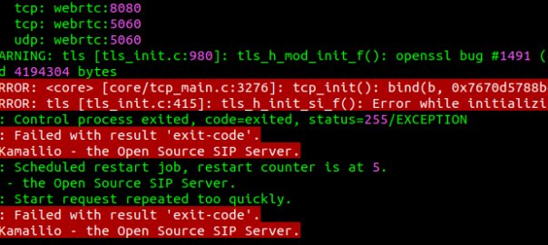
I run Ubuntu on my desktop and I mess with Kamailio a lot.
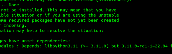
Recently I was doing some work with KEMI using Python, but installing the latest versions of Kamailio from the Debian Repos for Kamailio wasn’t working.
The following packages have unmet dependencies:
 kamailio-python3-modules : Depends: libpython3.11 (>= 3.11.0) but 3.11.0~rc1-1~22.04 is to be installed
Kamailio’s Python modules expect libpython3.11 or higher, but Ubuntu 22.04 repos only contain the release candidate – not the final version:
If you’re setting up Kamailio for support for WebSocket and need to bind to TCP port 80 or TCP port 443, you may run into the issue that permission is denied to bind to these ports when you try and start the service.
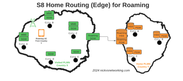
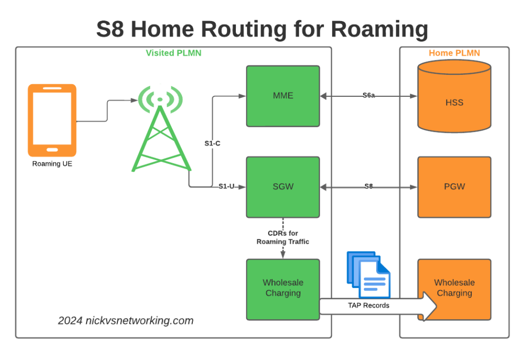
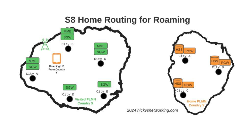
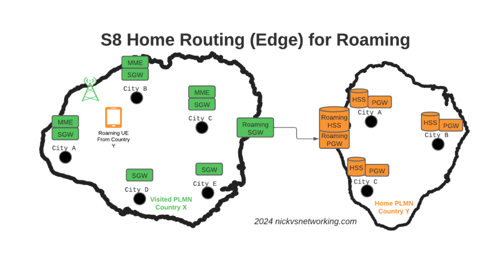
S8 Home Routing is a really simple concept, the traffic goes from the SGW in the visited PLMN to the PGW in the home PLMN, so the PCRF, OCS/OFCS, IMS, IP Addresses, etc, etc, are all in the home network, and this avoids huge amounts of complexity.
But in order for this to work, the visited network MME needs to find the PGW of the home network, and with over 700 roaming networks in commercial use, each one with potentially hundreds of unique APNs each routing to a different PGW, this is a tricky proposition.
If you’ve configured your PGW peers statically on your MME, that’s fine, but it doesn’t scale very well – And if you add an MVNO who wants their own PGW for serving their APN, well you’ll be adding some complexity there to, so what to do?
Well, the answer is DNS.
By taking the APN to be served, the home PLMN and the interface type desired, with some funky DNS queries, our MME can determine which PGW should be selected for a request.
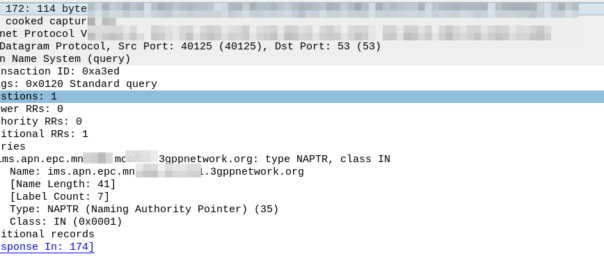
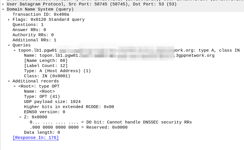
Let’s take a look, for a UE from MNC XXX MCC YYY roaming into our network, trying to access the “IMS” APN.
Our MME knows the network code of the roaming subscriber from the IMSI is MNC XXX, MCC YYY, and that the UE is requesting the IMS APN.
So our MME crafts a DNS request for the NAPTR query for ims.apn.epc.mncXXX.mccYYY.3gppnetwork.org:
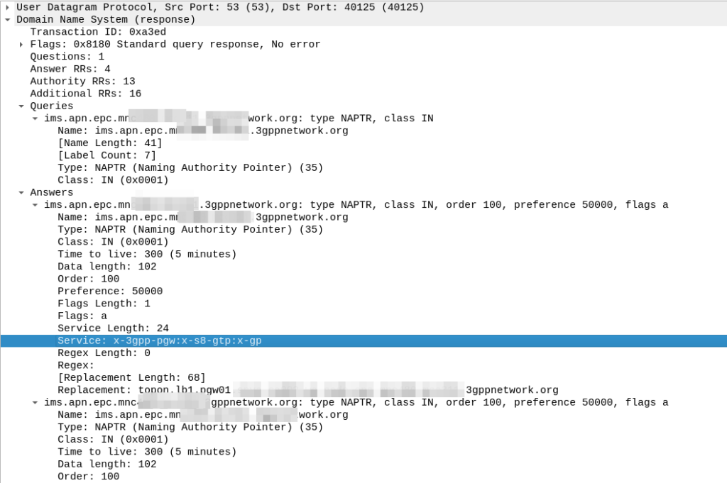
Because the domain is epc.mncXXX.mccYYY.3gppnetwork.org it’s routed to the authoritative DNS server in the home network, which sends back the response:
We’ve got a few peers to pick from, so we need to filter this list of Answers to only those that are relevant to us.
First we filter by the Service tag, whihc for each listed peer shows what services that peer supports.
But since we’re looking for S8, we need to find a peer who’s “Service” tag string contains:
x-3gpp-pgw:x-s8-gtp
We’re looking for two bits of info here, the presence of x-3gpp-pgw in the Service to indicate that this peer is a PGW and x-s8-gtp to indicate that this peer supports the S8 interface.
A service string like this:
x-3gpp-pgw:x-s5-gtp
Would be excluded as it only supports S5 not S8 (Even though they are largely the same interface, S8 is used in roaming).
It’s also not uncommon to see both services indicated as supported, in which case that peer could be selected too:
x-3gpp-pgw:x-s5-gtp:x-s8-gtp
(The answers in the screenshot include :x-gp which means the PGWs advertised are also co-located with a GGSN)
So with our answers whittled down to only those that meet our needs, we next use the Order and the Preference to pick our best candidate, this is the same as regular DNS selection logic.
From our candidate, we’ve also got the Regex Replacement, which allows our original DNS request to be re-written, which allows us to point at a single peer.
In our answer, we see the original request ims.apn.epc.mncXXX.mccYYY.3gppnetwork.org is to be re-written to topon.lb1.pgw01.epc.mncXXX.mccYYY.3gppnetwork.org.
This is the FQDN of the PGW we should use.
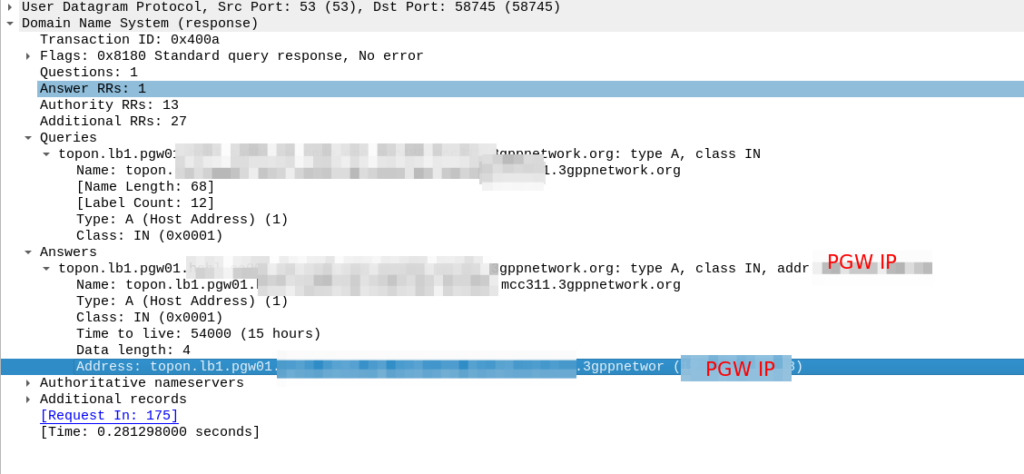
Now we know the FQND we should use, we just do an A-Record lookup (Or AAAA record lookup if it is IPv6) for that peer we are targeting, to turn that FQDN into an IP address we can use.
And then in comes the response:
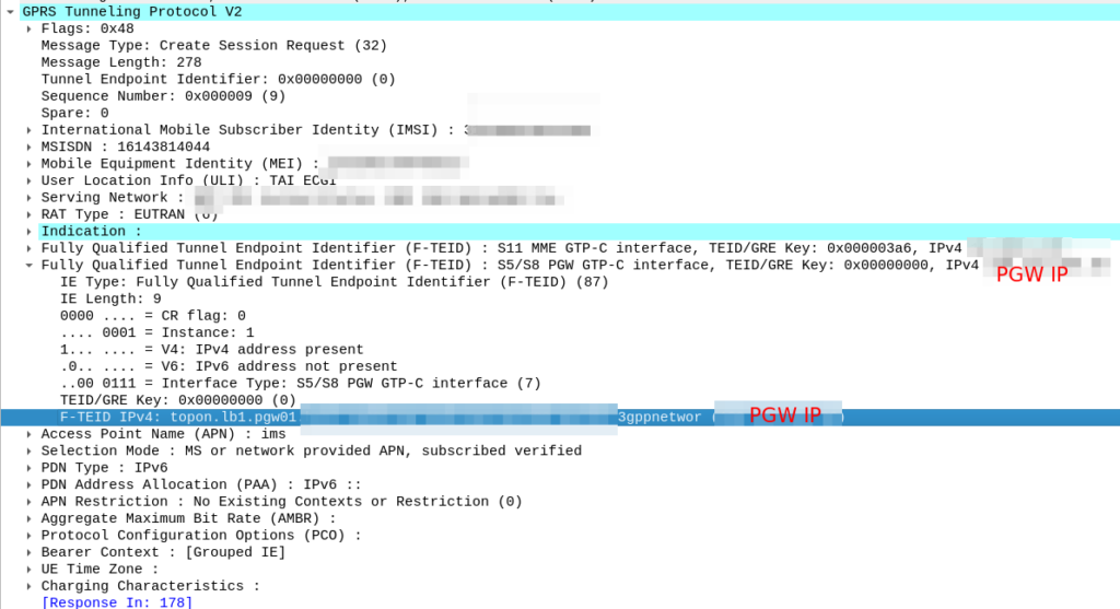
So now our MME knows the IP of the PGW, it can craft a Create Session request where the F-TEID for the S8 interface has the PGW IP set on it that we selected.
For more info on this TS 129.303 (Domain Name System Procedures) is the definitive doc, but the GSMA’s IR.88 “LTE and EPC Roaming Guidelines” provides a handy reference.
While vCenter doesn’t really do contexts / mutli-tenants / VPCs like the hyperscalers, there are simple (ish) ways to do context separation inside VMware vCenter.
This means you can have a user who only has access to say a folder of VMs, but not able to see VMs outside of that folder.
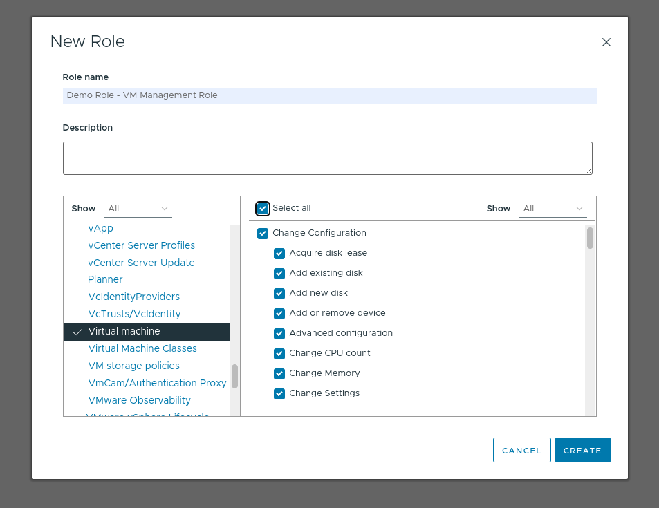
Create a new Role inside vCenter from Administration -> Roles -> Add
Give the role all Virtual Machine privileges:
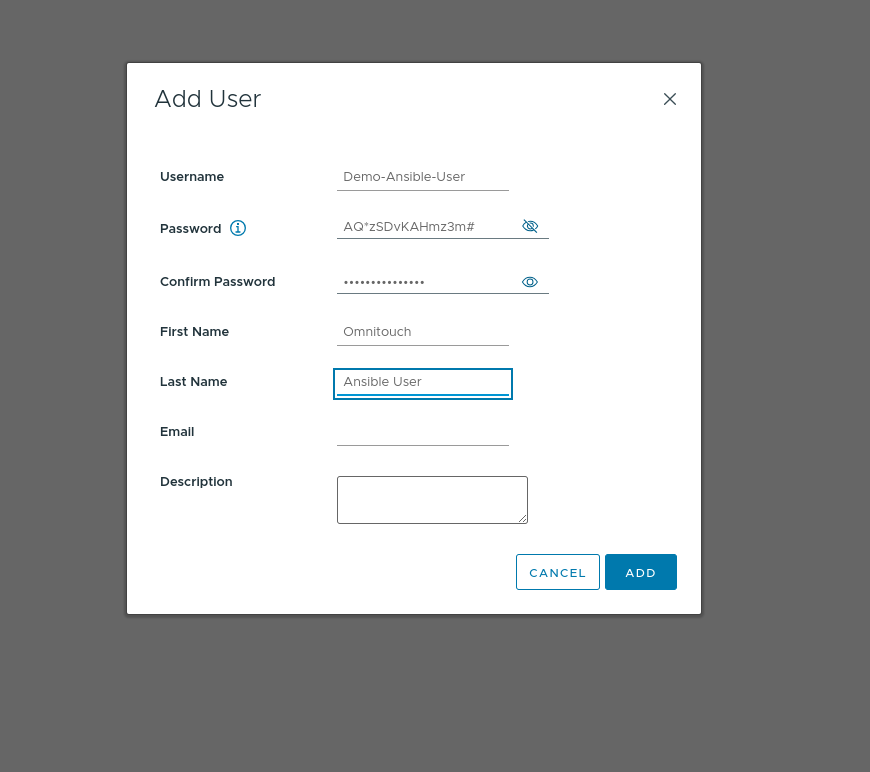
Create a new account (Can be on AD if you’re not using Local accounts, this is just our lab so I’ve created it as a Local account) for the user. We’re using this account for Ansible so we’ve used “Demo-Ansible-User” as the username
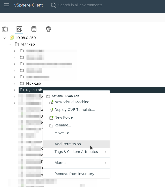
Now create a folder for the group of VMs, or pick an existing folder you want to give access to.
Right click on the folder and select “Add Permission”.
We give permission to that user with that role on the folder and make sure you tick “Propagate to children” (I missed this step before and had to repeat it):
If you are using templates, make sure the template is either in the folder, or apply the same permission to the template, by right clicking on it, Add Permission, same as this.
Finally you should be able to log in as that user and see the template, and clone it from the web UI, or create VMs but only within that folder.
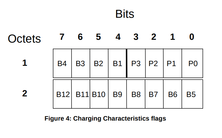
How does one encode / interpret the value of this AVP / IE was the question I set out to answer.
TS 29.274 says:
For the encoding of this information element see 3GPP TS 32.298
TS 32.298 says:
The functional requirements for the Charging Characteristics as well as the profile and behaviour bits are further defined in normative Annex A of TS 32.251
TS 32.251 Annex A says:
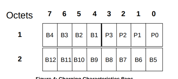
The Charging Characteristics parameter consists of a string of 16 bits designated as Behaviours (B), freely defined by Operators, as shown in TS 32.298 [51]. Each bit corresponds to a specific charging behaviour which is defined on a per operator basis, configured within the PCN and pointed when bit is set to “1” value.
After a few circular references I found this is imported from 32.298.
Finally we find some solid answers hidden away in TS 132 215, under the Charging Characteristics Profile index.
Charging Characteristics consists of a string of 16 bits designated as Profile (P) and Behaviour (B), shown in Figure 4. The first four bits (P) shall be used to select different charging trigger profiles, where each profile consists of the following trigger sets:
S-CDR: activate/deactivate CDRs, time limit, volume limit, maximum number of charging conditions, tariff times;
G-CDR: same as SGSN, plus maximum number of SGSN changes;
M-CDR: activate/deactivate CDRs, time limit, and maximum number of mobility changes;
SMS-MO-CDR: activate/deactivate CDRs;
SMS-MT-CDR: active/deactivate CDRs.
The Charging Characteristics field allows the operator to apply different kind of charging methods in the CDRs. A subscriber may have Charging Characteristics assigned to his subscription. These characteristics can be supplied by the HLR to the SGSN as part of the subscription information, and, upon activation of a PDP context, the SGSN forwards the charging characteristics to the GGSN on the Gn / Gp reference point according to the rules specified in Annex A of TS 32.251 [11].
This information can be used by the GSNs to activate CDR generation and control the closure of the CDR or the traffic volume containers (see clause 5.1.2.2.23) and is included in CDRs transmitted to nodes handling the CDRs via the Ga reference point. It can also be used in nodes handling the CDRs (e.g., the CGF or the billing system) to influence the CDR processing priority and routing.
These functions are accomplished by specifying the charging characteristics as sets of charging profiles and the expected behaviour associated with each profile.
The interpretations of the profiles and their associated behaviours can be different for each PLMN operator and are not subject to standardisation. In the present document only the charging characteristic formats and selection modes are specified.
The functional requirements for the Charging Characteristics as well as the profile and behaviour bits are further defined in normative Annex A of TS 32.251 [11], including the definitions of the trigger profiles associated with each CDR type.
The format of charging characteristics field is depicted in Figure 4. Px (x =0..3) refers to the Charging Characteristics Profile index. Bits classified with a “B” may be used by the operator for non-standardised behaviour (see Annex A of TS 32.251 [11]).
Right, well hopefully next time someone goes looking for this info you’ll find it a bit more easily than I did!
The S8 Home Routing approach for LTE Roaming works really well, as more and more operators are switching off their legacy circuit switched 2G/3G networks and shifting to LTE & VoLTE for roaming, we’re seeing more an more S8-HR deployments.
When LTE was being standardised in 2008, Local Breakout (LBO) and S8 Home Routing were both considered options for how roaming may look. Fast forward to today, and S8 Home routing is the only way roaming is done for modern deployments.
In light of this, there are some “best practices” in an “all S8 Home Routed” world, we’ve developed, that I thought I’d share.
The Basics
When roaming, the SGW in the Visited Network, sends user traffic back to the PGW in the Home Network.
This means Online/Offline charging, IMS, PCRF, etc, is all done in the Home PLMN. As long as data packets can get from the SGW in the Visited PLMN to the PGW in the Home PLMN, and authentication flows from the Visited MME to the HSS in the Home PLMN, you’re golden.
The Constraints
Of course real networks don’t look as simple as this, in reality a roaming scenario for a visited network has a lot more nodes, which need to be
Building Distributed Packet Core & IMS
Virtualization (VNF / CNF) has led operators away from “big iron” hardware for Packet Core & IMS nodes, towards software based solutions, which in turn offer a lot more flexibility.
Best practice for design of User Plane is to keep the the latency down, by bringing the user plane closer to the user (the idea of “Edge” UPFs in 5GC is a great example of this), and the move away from “big iron” in central locations for SGW and PGW nodes has been the trend for the past decade.
So to achieve these goals in the networks we build, we geographically distribute the core network.
This means we’ve got quite a few S-GW, P-GW, MME & HSS instances across the network. There’s some real advantages to this approach:
From a redundancy perspective this allows us to “spread the load” and build far more resilient networks. A network with 20 smaller HSS instances spread around the country, is far more resilient than 2 massive ones, regardless of how many power feeds or redundant disks it may have.
This allows us to be more resource efficient. MNOs have always provisioned excess capacity to cater for the loss of a node. If we have 2 MMEs serving a country, then each node has to have at least 50% capacity free, so if one MME were to fail, the other MME could handle the additional load it from it’s dead friend. This is costly for resources. Having 20 MMEs means each MME has to have 5% capacity free, to handle the loss of one MME in the pool.
It also forces our infrastructure teams to manage infrastructure “as cattle” rather than pets. These boxes don’t get names or lovingly crafted, they’re automatically spun up and destroyed without thinking about it.
For security, we only use internal IP addresses for the nodes in our packet core, this provides another layer of protection for the “crown jewels” of our network, so no one messing with BGP filtering can accidentally open the flood gates to our core, as one US operator learned leaving a GGSN open to the world leading to the private information for 100 million customers being leaked.
What this all adds to, is of course, the end user experience. For the end subscriber / customer, they get a better experience thanks to the reduced latency the connection provides, better uptime and faster call setup / SMS delivery, and less cost to deliver services.
I love this approach and could prothletise about it all day, but in a roaming context this presents some challenges.
The distributed networks we build are in a constant state of flux, new capacity is being provisioned in some areas, nodes things decommissioned in others, and our our core nodes are only reachable on internal IPs, so wouldn’t be reachable by roaming networks.
Our Distributed-Core Roaming Solution
To resolve this we’ve taken a novel approach, we’ve deployed a pair of S-GWs we call the “Roaming SGWs”, and a pair of P-GWs we call the “Roaming PGWs”, these do have public IPs, and are dedicated for use only by roaming traffic.
We really like this approach for a few reasons:
It allows us to be really flexible do what we want inside the network, without impacting roaming customers or operators who use our network for roaming. All the benefits I described from the distributed architectures can still be realised.
From a security standpoint, only these SGW/PGW pairs have public IPs, all the others are on internal IPs. This good for security – Our core network is the ‘crown jewels’ of the network and we only expose an edge to other providers. Even though IPX networks are supposed to be secure, one of the largest IPX providers had their systems breached for 5 years before it was detected, so being almost as distrustful of IPX traffic as Internet traffic is a good thing. This allows us to put these PGWs / SGWs at the “edge” of our network, and keep all our MMEs, as well as our on-net PGW and SGWs, on internal IPs, safe and secure inside our network.
For charging on the SGWs, we only need to worry about collecting CDRs from one set of SGWs (to go into the TAP files we use to bill the other operators), rather than running around hoovering up SGW CDRs from large numbers of Serving Gateways, which may get blown away and replaced without warning.
Of course, there is a latency angle to this, for international roaming, the traffic has to cross the sea / international borders to get to us. By putting it at the edge we’re seeing increased MOS on our calls, as the traffic is as close to the edge of the network as can be.
Caveat: Increased S11 Latency on Core Network sites over Satellite
This is probably not relevant to most operators, but some of our core network sites are fed only by satellite, and the move to this architecture shifted something: Rather than having latency on the S8 interface from the SGW to the PGW due to the satellite hop, we’ve got latency between the MME and the SGW due to the satellite hop.
It just shifts where in the chain the latency lies, but it did lead to us having to boost some timers in the MME and out of sequence deliver detection, on what had always been an internal interface previously.
Evolution to 5G Standalone Roaming
This approach aligns to the Home Routed options for 5G-SA roaming; UPF chaining means that the roaming traffic can still be routed, as seems to be the way the industry is going.
SA roaming is in its infancy, without widely deployed SA networks, we’re not going to see common roaming using SA for a good long while, but I’ll be curious to see if this approach becomes the de facto standard going forward.
Where to from here?
We’re pretty happy with this approach in the networks we’ve been building.
So far it’s made IREG testing easier as we’ve got two fixed points the IPX needs to hit (The DRAs and the SGWs) rather than a wide range of networks.
Operators with a vast number of APNs they need to drop into different VRFs may have to do some traffic engineering here – Our operations are generally pretty flat, but I can see where this may present some challenges for established operators shifting their traffic.
I’d be keen to hear if other operators are taking this approach and if they’ve run into any issues, or any issues others can see in this, feel free to drop a comment below.
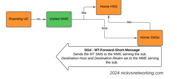
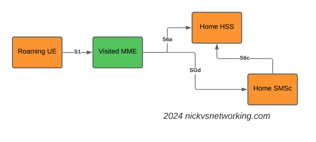
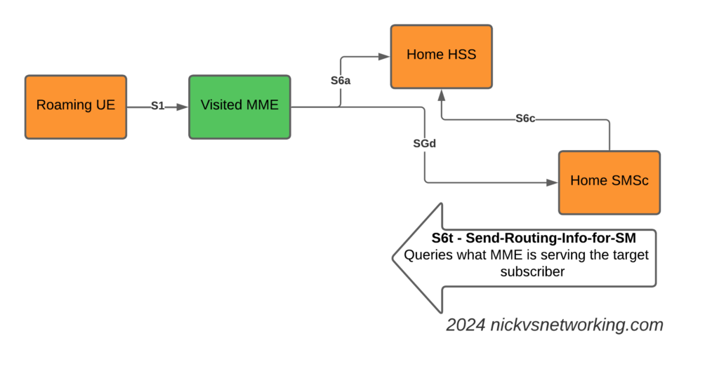
SGs-AP which is used for CSFB & SMS doesn’t span network borders (you can’t roam with SGs-AP), and with SMSoIP out of the question, that gave us the option of MAP or Diameter, so we picked Diameter.
This introduces the S6c and SGd Diameter interfaces, in the diagrams below Orange is the Home Network (HPMN) and the Green is the Visited Network (VPMN).
The S6c interface is used between the SMSc and the HSS, in order to retrieve the routing information. This like the SRI-for-SM in MAP.
The SGd interface is used between the MME serving the UE and the SMSc, and is used for actual delivery of the MO/MT messages.
I haven’t shown the Diameter Routing Agents in these diagrams, but in reality there would be a DRA on the VPLMN and a DRA on the HPMN, and probably a DRA in the IPX between them too.
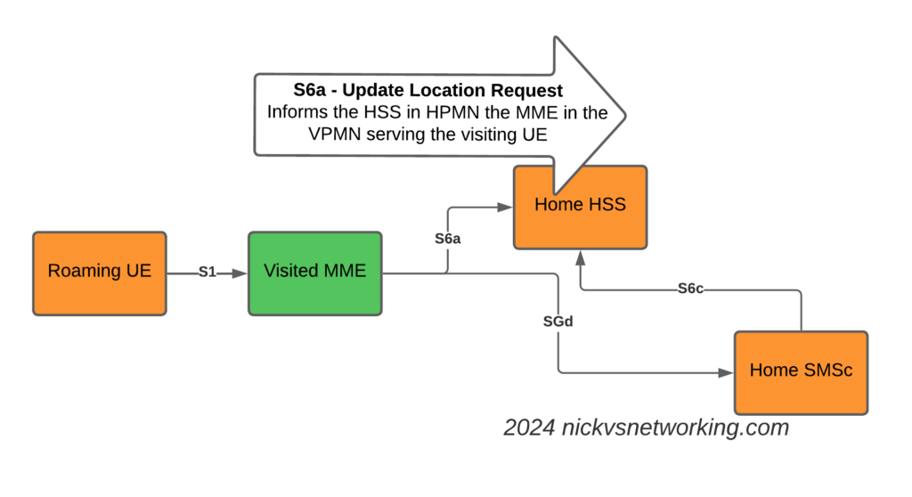
The Attach
The attach looks like a regular roaming attach, the MME in the Visited PMN sends an Update Location Request to the HSS, so the HSS knows the MME that is serving the subscriber.
S6a Update Location Request to indicate the MME serving the Subscriber
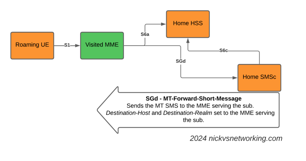
The Mobile Terminated SMS Flow
Now we introduce the S6c interface and the SGd interfaces.
When the Home SMSc has a message to send to the subscriber (Mobile Terminated SMS) it runs a the Send-Routing-Info-for-SM-Request (SRR) dialog to the HSS.
The Send-Routing-Info-for-SM-Answer (SRA) back from the HSS contains the info on the MME Diameter Host name and Diameter Realm serving the subscriber.
S6t – Send-Routing-Info-for-SM request to get the MME serving the subscriber
With this info, we can now craft a Diameter Request that will get sent to the MME serving the subscriber, containing the SMS PDU to send to the UE.
SGd MT-Forward-Short-Message to deliver Mobile Terminated SMS to the serving MME
We make sure it’s sent to the correct MME by setting the Destination-Host and Destination-Realm in the Diameter request.
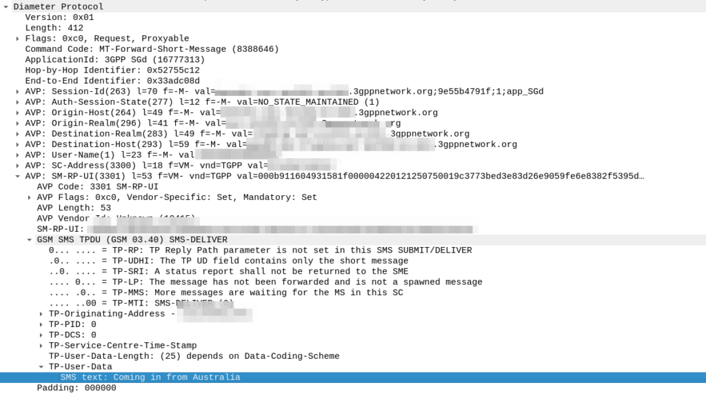
Here’s how the request looks from the SMSc towards our DRA:
As you can see the Destination Realm and Destination-Host is set, as is the User-Name set to the IMSI of the UE we want to send the message to.
And down the bottom you can see the SMS-TPDU, the same as it’s been all the way back since GSM days.
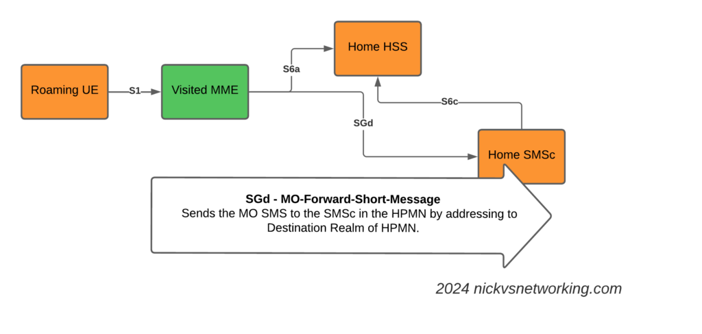
The Mobile Originated SMS Flow
The Mobile Originated flow is even simpler, because we don’t need to look up where to route it to.
The MME receives the MO SMS from the UE, and shoves it into a Diameter message with Application ID set to SGd and Destination-Realm set to the HPMN Realm.
When the message reaches the DRA in the HPMN it forwards the request to an SMSc and then the Home SMSc has the message ready to roll.
Having rated CDRs in CGrateS is great, but in reality, you probably want to get them into a billing system, CSV file, S3 bucket, CRM, invoice, Grafana, SQL table, etc, etc.
The Event Exporter Service (EES (previously called CDRe)) handles exporting CDRs from CGrateS.
Like everything in CGrateS, it’s highly configurable, and, again, like everything in CGrateS, supports every combination of services you can think of, plus a stack you haven’t thought of.
CDRs can be exported one of two ways, in real time, as the CDR is generated (online), or after the fact, exporting from the database containing the CDRs (offline).
Exporting in realtime (online) is a great option if you don’t want (or need) to store the CDRs in CGrateS; if you’re just using CGrateS to rate calls and spit them into a seperate system, this is a fantastic option, as it allows your CGrateS instances to remain light and not get clogged up with lots of old CDRs – That said, of course you can export the CDRs in realtime and still store them in CGrateS, that’s also a totally valid approach as well.
The more traditional approach is offline CDR export, where periodically or when an event is triggered, you scrape up a pile of CDRs and send them to your external systems.
For both options, we’ll need to define at least one exporter in our cgrates.json config file. For this example we’ll define a HTTP POST that we will trigger for realtime (online) CDR exporting, and a CSV file we dump to periodically when called from the API.
So first things first, we enable the EES module in the config:
"ees": {
		"enabled": true,
		"exporters": [
		]
	}
We’ll start with defining one exporter, named CSVExporter, that will output files to a folder named “testCSV” in the /tmp/ directory, but you can plonk these files wherever you like:
We’ve got a lot of different types of export available to us, but type *file_csv is the easiest, so that’s where we’ll start.
Setting synchronous to true will mean we’ll only run one export job at a time, but it also means we’ll get back the result via the API, which will allow us to keep track of the ID of the last record we updated, so we don’t export the same record multiple times, more on this later.
Flags allows us to, if we wanted, bounce the event through AttributeS, for example, by adding *attributes to the flags, but in this case, it’s just logging to syslog.
Of course, just enabling ees won’t actually send calls to it, we’ll need to add “ees_conns“: [“*localhost”], to “apiers”: and “cdrs” so they know to bounce the events through it:
If you’ve already got CDRs on your system from our previous tutorial, fantastic, but if not, let’s get up and running with a quick and dirty script to define some destinations, a charger, an account balance and then use some of the balance to generate a CDR:
import cgrateshttpapi
import pprint
import uuid
import datetime
now = datetime.datetime.now()
CGRateS_Obj = cgrateshttpapi.CGRateS('localhost', 2080)

#Define Destinations
CGRateS_Obj.SendData({'method':'ApierV2.SetTPDestination','params':[{"TPid":'cgrates.org',"ID":"Dest_AU_Mobile","Prefixes":["614"]}]})

#Load TariffPlan we just defined from StorDB to DataDB
CGRateS_Obj.SendData({"method":"APIerSv1.LoadTariffPlanFromStorDb","params":[{"TPid":'cgrates.org',"DryRun":False,"Validate":True,"APIOpts":None,"Caching":None}],"id":0})

#Define default Charger
print(CGRateS_Obj.SendData({"method": "APIerSv1.SetChargerProfile","params": [{"Tenant": "cgrates.org","ID": "DEFAULT",'FilterIDs': [],'AttributeIDs' : ['*none'],'Weight': 0,}]}))

account = "Nick_Test_123"

#Add a balance to the account with type *sms with 100 sms events
pprint.pprint(CGRateS_Obj.SendData({"method": "ApierV1.SetBalance","params": [{"Tenant": "cgrates.org","Account": account,"BalanceType": "*sms","DestinationIDs": 'Dest_NZ_Mobile;Dest_AU_Mobile',"Categories": "*any","Balance": {"ID": "100_SMS_Bundle_AU_NZ_Mobile","Value": 100,"Weight": 25}}]}))

#Process CDR Event for a single SMS
pprint.pprint(CGRateS_Obj.SendData({"method": "CDRsV2.ProcessExternalCDR","params": [{"OriginID": str(uuid.uuid1()),"ToR": "*sms","RequestType": "*pseudoprepaid","AnswerTime": now.strftime("%Y-%m-%d %H:%M:%S"),"SetupTime": now.strftime("%Y-%m-%d %H:%M:%S"),"Tenant": "cgrates.org","Account": account,"Destination" : "61412345678","Usage": "1",}]}))
Right, with that out of the way, we should now have something in our CDRs table, a quick SQL query confirms this is the case:
So, as you may have guessed, we’ve called the ExportCDRs API endpoint, we’ve specified which ExporterIDs we want to reference (these link back to the objects in the config, and the one we have defined currently is named CSVExporter).
Setting Verbose: True means that CGrateS gives us back a lot of info from the API call, here’s what we get back:
Now that looks pretty positive, we got 12 events of SMS usage exported, which we can see in the file /tmp/testCSV/CSVExporter_21e9bc2.csv – and if we cat out the file, yeap, there’s all the CDRs.
But it’s a bit of a mess, there’s a lot of fields in there, so let’s adjust what goes into the CSV.
Let’s start by filtering what goes into the exporter, to only give us SMS events, of course you could adjust the filters here to target exporting only the records you want, based on anything you can define with Filters (and there’s a lot you can define with filters).
Now we’re only exporting SMS records, so let’s clean up the output of the CSV to just give us the data we want, which is the CDR ID, time, account, destination and usage.
Now after a restart of CGrateS, our exports look like this:
Stunning, truly beautiful, look at that output!
Right, well you may at this point have noticed a problem if you’ve run this more than once. The problem is that is every time we run this, we get all the CDRs since the beginning of time.
But where filtering by date/time falls down, is that if an offline CDR of a call on Monday, only got ingested on Tuesday, it would be missed by the export.
But, setting Verbose: True on the ExportCDRs API call gives us a handy trick, we’ve been told what the highest ID in the CDRs table we just exported in the response from the API in LastExpOrderID field.
If we jump over to the SQL database we use for StorDB, we can see that 33 is the ID of the highest CDR in the system.
So let’s try something, let’s run the exporter again, but this time let’s get all the CDRs where the ID is higher than 33:
#Process CDR Event for a single SMS
pprint.pprint(CGRateS_Obj.SendData({"method": "CDRsV2.ProcessExternalCDR","params": [{"OriginID": str(uuid.uuid1()),"ToR": "*sms","RequestType": "*pseudoprepaid","AnswerTime": now.strftime("%Y-%m-%d %H:%M:%S"),"SetupTime": now.strftime("%Y-%m-%d %H:%M:%S"),"Tenant": "cgrates.org","Account": account,"Destination" : "61412345678","Usage": "1",}]}))

#Trigger export where the OrderID is above 33
result = CGRateS_Obj.SendData({"method":"APIerSv1.ExportCDRs","params":[
    {"ExporterIDs": ["CSVExporter"],
     "Verbose" : True,
     "ExtraArgs" : {
        "OrderIDStart" : int(33),
     },
     "Accounts" : [account]}
]})
pprint.pprint(result)
Boom, now if we have a look at the output we can see the export covered two records, and the last ID was 35.
So as long as we keep track of the LastExpOrderID value, and feed that as in input every time we run ExportCDRs, we can ensure we never miss a CDR, and never get the same CDR twice.
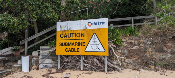
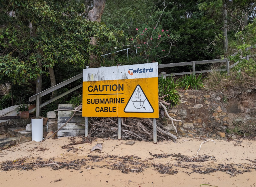
Recently I took a week off work and went hiking around the Hawkesbury river in NSW.
This did not mean I stopped thinking about telecom.
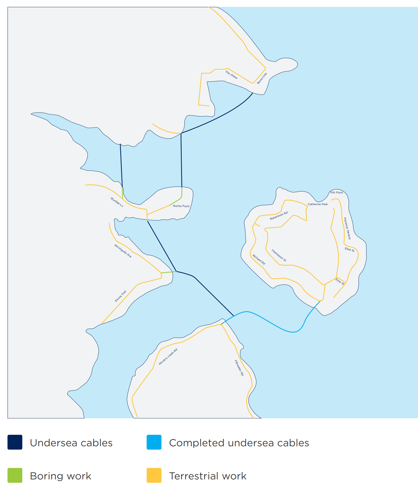
There’s a lot of beautiful bushland and some fancy houses nestled into the area, a good chunk of which are not accessible by road at all, with the only way to access them being by boat or a long hike along a bush track.
No fancy erbium-doped fiber amplifiers here though, just regular GPON laid on the riverbed.
Telstra / Telecom had previously laid a copper 100 pair (seemingly just regular gel filled cable directly on the riverbed without any protection) to service the area, and then aerial distribution along the tracks connecting the homes.
NBNco it seems opted for a slightly safer approach and used Protectorshell articulated pipe to protect the cables in the water / on the beaches.
Strange tree roots – NBN Articulated pipe on the left with the old copper 100 pair on the right
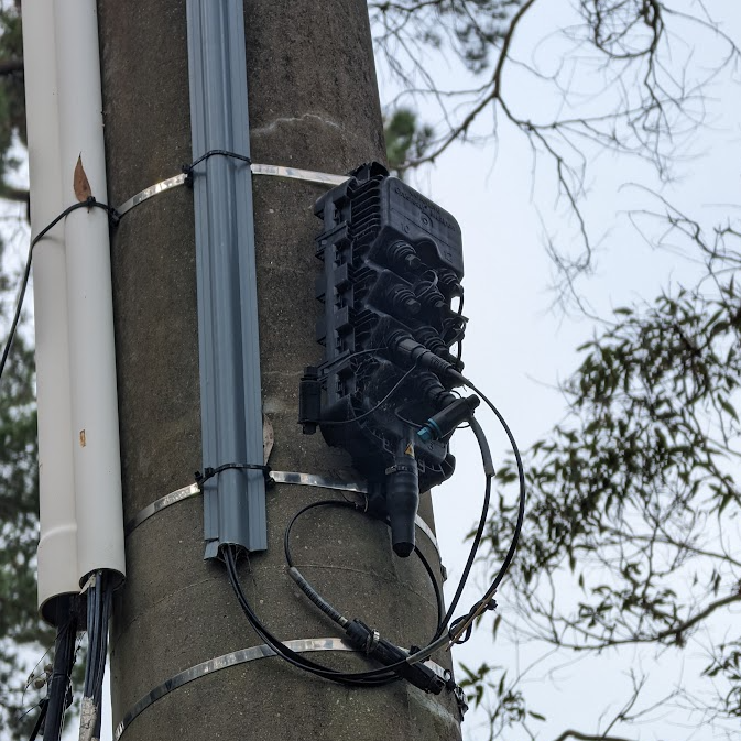
Once the cables land it’s back to regular NBN Aerial fiber runs, with DPUs on the power poles.
Apart from a few interesting catenary runs, and the fact there are no roads, once the fibre lands it’s very much a standard aerial NBN deployment.
There’s some great pics below from the supplier websites and local news site:
To make more Money (This post, congratulations, you’re reading it!)
Because they have to (Regulatory compliance, insurance, taxes, etc) – That’s the next post
So let’s look at SA in this context.
5G-SA can drive new revenue streams
We (as an industry) suck at this.
Last year on the Telecoms.com podcast, Scott Bicheno made the point that if operators took all the money they’d gambled (and lost) on trying to play in the sports rights, involvement in media companies, building their own streaming apps, attempts at bundling other utilities, digital identity, etc, and just left the cash in the bank and just operated the network, they’d be better off.
Uber, Spotify, “OTTs”, etc, utilize MNOs to enable their services, but operators don’t see this extra revenue. While some operators may talk of “fair share” the truth is, these companies add value to our product (connectivity) which as an industry, we’ve failed to add ourselves.
If the Metaverse does turn out to be a cash cow, it is unlikely the telecommunications industry will be the ones milking it.
Claim: Customers are willing to pay more for 5G-SA
This myth seems to be fairly persistent, but with minimal data to support this claim.
While BSS vendors talk about “5G Monetization”, the truth is, people use their MNO to provide them connectivity. If the coverage is adequate, and the speed enough to do what they need to do, few would be willing to pay any additional cash each month to see higher numbers on a speedtest result (enabled by 5G-NSA) and even fewer would pay extra cash for, well, whatever those features only enabled by 5G-Standalone are?
With most consumers now also holding onto their mobile devices for longer periods of time, and with interest rates reining in consumer spending across the board, we are seeing the rise of a more cost conscious consumer than ever before. If we want to see higher ARPUs, we need to give the consumer a compelling reason to care and spend their cash, beyond a speed test result.
We talk a little about APIs lower down in the post.
Claim: Users want Ultra-Low Latency / High Reliability Comms that only 5G-SA delivers
Wanting to offer a product to the market, is not the same as the market wanting a product to consume.
Telecom operators want customers to want these services, but customer take up rates tell a different story. For a product like this to be viable, it must have a wide enough addressable market to justify the investment.
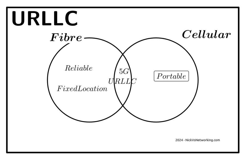
Reliability
The URLCC standards focus on preventing packet loss, but the world has moved on from needing zero packet loss.
The telecom industry has a habit of deciding what customers want without actually listening. When a customer talks about wanting “reliable” comms, they aren’t saying they want zero packet loss, but rather fewer dropouts or service flaps. For us to give the customer what they are actually asking for involves us expanding RAN footprint and adding transmission diversity, not 5G-SA.
The “protocols of the internet” (TCP/IP) have been around for more than 50 years now.
These protocols have always flowed over transport links with varied reliability and levels of packet loss.
Thanks to these error correction and retransmission techniques built into these protocols, a lost packet will not interrupt the stream. If your nuclear command and control network were carried over TCP/IP over the public internet (please don’t do this), a missing packet won’t lead to worldwide annihilation, but rather the sender will see the receiver never acknowledged the receipt of the packet at the other end, and resend it, end of.
If you walk into a hospital today, you’ll find patient monitoring devices, tracking the vital signs for patients and alerting hospital staff if a patient’s vital signs change. It is hard to think of more important services for reliability than this.
And yet they use WiFi, and have done for a long time, if a packet is lost on WiFi (as happens regularly) it’s just retransmitted and the end user never knows.
Autonomous cars are unlikely to ever rely on a 5G connection to operate, for the simple reason that coverage will never be 100%. If your car stops because you’re in a not-spot, you won’t be a happy customer. While plenty of cars have cellular modems in them, that are used to upload telemetry data back to the manufacturer, but not to drive the car.
One example of wireless controlled vehicles in the wild is autonomous haul trucks in mines. Historically, these have used WiFi for their comms. Mine sites are often a good fit for Private LTE, but there’s nothing inherent in the 5G Standalone standard that means it’s the only tool for the job here.
Slicing
Slicing is available in LTE (4G), with an architecture designed to allow access to others. It failed to gain traction, but is in networks today.
The RAN a piece of the latency puzzle here, but it is just one piece of the puzzle.
If we look at the flow a packet takes from the user’s device to the server they want to talk to we’ve got:
Time it takes the UE to craft the packet
Time it takes for the packet to be transmitted over the air to the base station
Time it takes for the packet to get through the RAN transmission network to the core
Time it takes the packet to traverse the packet core
Time it takes for the packet to get out to transit/peering
Time it takes to get the packet from the edge of the operators network to the edge of the network hosting the server
Time it takes the packet through the network the server is on
Time it takes the server to process the request
The “low latency” bit of the 5G puzzle only involves the two elements in bold.
If you’ve got to get from point A to point B along a series of roads, and the speed limit on two of the roads you traverse (short sections already) is increased. The overall travel time is not drastically reduced.
I’m lucky, I have access to a well kitted out lab which allows me to put all of these latency figures to the test and provide side by side metrics. If this is of interest to anyone, let me know. Otherwise in the meantime you’ll just have to accept some conjecture and opinion.
You could rebut this talking about Edge Compute, and having the datacenter at the base of the tower, but for a number of fairly well documented reasons, I think this is unlikely to attract widespread deployment in established carrier networks, and Intel’s recent yearly earning specifically called this out.
Claim: Customers want APIs and these needs 5G SA
Companies like Twilio have made it easy to interact with the carrier network via their APIs, but yet again, it’s these companies producing the additional value on a service operated by the MNOs.
My coffee machine does not have an API, and I’m OK with this because I don’t have a want or need to interact with it programatically.
By far, the most common APIs used by businesses involving telco markets are APIs to enable sending an SMS to a user.
These have been around for a long time, and the A2P market is pretty well established, and the good news is, operators already get a chunk of this pie, by charging for the SMS.
Imagine a company that makes medical booking software. They’re a tech company, so they want their stack to work anywhere in the world, and they want to be able to send reminder SMS to end users.
They could get an account manager with each of the telcos in each of the markets they work in, onboard and integrate the arcane complexities of each operators wholesale SMS system, or they could use Twilio or a similar service, which gives them global reach.
Often the cost of services like Twilio are cheaper than working directly with the carriers in each market, and even if it is marginally more expensive, the cost savings by not having to deal with dozens of carriers or integrate into dozens of systems, far outweighs this.
While it’s a great idea, in the context of 5G Standalone and APIs, it’s worth noting that none of the use cases in OpenGateway require 5G Standalone (Except possibly Edge discovery, but it is debatable).
Critically, from a developer experience perspective:
I can sign up to services like Twilio without a credit card, and start using the service right away, with examples in my programming language of choice, the developer user experience is fantastic.
Jump on the OpenGateway website today and see if you can even find a way to sign up to use the service?
Claim: Fixed Wireless works best with 5G-SA
Of all the touted use cases and applications for 5G, Fixed Wireless (FWA) has been the most successful.
The great thing about FWA on Cellular networks is you can use the same infrastructure you use for your mobile customers, and then sell excess capacity in the network to deliver Fixed Wireless Access services, better utilizing an asset (great!).
But again, this does not require Standalone 5G. If you deploy your FWA network using 5G SA, then you won’t be able to sweat that same asset for both mobile subscribers and FWA subscribers.
Today at least, very few handsets short of this generation of flagship phones, supports 5G SA. Even the phones sold as supporting 5G over the past few years, are almost all only supporting 5G-NSA, so if you rolled out your FWA network as Standalone, you can’t better utilize the asset by sharing with your existing LTE/5G-NSA customers.
Claim: The Killer App is coming for 5G and it needs 5G SA
This space is reserved for the killer app that requires 5G Standalone.
Whenever that comes?
Anyone?
I’m not paying to build a marina berth for my mega yacht, mostly because I don’t have one. Ditto this.
Could you explain to everyone on an investor call that you’re investing in something where the vessel of the payoff isn’t even known to exist? Telecom is “blue chip”, hardly speculative.
The Future for Revenue Growth?
Maybe there isn’t one.
I know it’s an unthinkable thought for a lot of operators, but let’s look at it rationally; in the developed world, everyone who wants a mobile service already has one.
This leaves operators with two options; gaining market share from their competitors and selling more/higher priced services to existing customers.
You don’t steal away customers from other operators by offering a higher priced product, and with reduced consumer spending people aren’t queuing up to spend more each month.
But there is a silver lining, if you can’t grow revenues, you can still shrink expenditure, which in the end still gets the same result at the end of the quarter – More cash.
Simplify your operations, focus on what you do really well (mobile services), the whole 80/20 rule, get better at self service, all that guff.
There’s no shortage of pain points for consumers telecom operators could address, to make the customer experience better, but few that include the word Slicing.
No one spends marketing dollars talking about the problems with a tech and vendors aren’t out there promoting sweating existing assets. But understanding your options as an operator is more important now than ever before.
Sidebar; This post got really long, so I’m splitting it into 3…
We’re often asked to help define a a 5G strategy for operators; while every case is different, there’s a lot of vendors pushing MNOs to move towards 5G standalone or 5G-SA.
I’m always a fan of playing “devil’s advocate“, and with so many articles and press releases singing the praises of standalone 5G/5G-SA, so as a counter in this post, I’ll be making the case against the narratives presented to operators by vendors that the “right” way to do 5G is to introduce 5G Standalone, that they should all be “upgrading” to Standalone 5G.
With Mobile World Congress around the corner, now seems like a good time to put forward the argument against introducing 5G Standalone, rebutting some common claims about 5G Standalone operators will be told. We’ll counterpoint these arguments and I’ll put forward the case for not jumping onto the 5G-SA bandwagon – just yet.
On a personal note, I do like 5G SA, it has some real advantages and some cool features, which are well documented, including on this blog. I’m not looking to beat up on any vendors, marketing hype or events, but just to provide the “other side” of the equation that operators should consider when making decisions and may not be aware of otherwise. It’s also all opinion of course (cited where possible), but if you’re going to build your network based on a blog post (even one as good as this) you should probably reconsider your life choices.
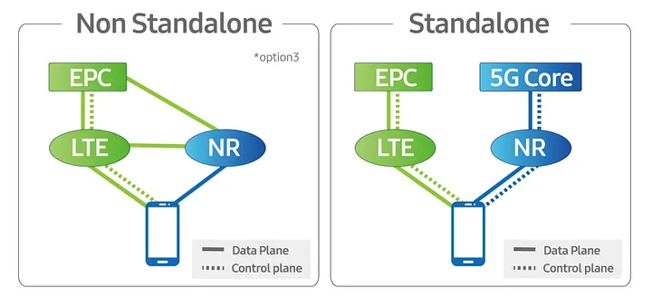
Some Arcane Detail: 5G Non-Standalone (NSA) vs Standalone (SA)
5G NSA (Non Standalone) uses LTE (4G) with an additional layer “bolted on” that uses 5G on the radio interface to provide “5G” speeds to users, while reusing the existing LTE (Evolved Packet Core) core and VoLTE for voice / SMS.
From an operator perspective there is almost no change required in the network to support NSA 5G, other than in the RAN, and almost all the 5G networks in commercial use today use 5G NSA.
5G NSA is great, it gives the user 5G speeds for users with phones that support it, with no change to the rest of the network needed.
Standalone 5G on the other hand requires an a completely new core network with all the trimmings.
While it is possible to handover / interwork with LTE/4G (Inter-RAT Handovers), this is like 3G/4G interworking, where each has a different core network. Introducing 5G standalone touches every element of the network, you need new nodes supporting the new standards for charging, policy, user plane, IMS, etc.
Scope
There’s an old adage that businesses spend money for one of three reasons:
To Save Money (Which we’ll cover in this post)
To make more Money (Covered next – Will link when published)
Because they have to (Regulatory compliance, insurance, taxes, etc)
Let’s look at 5G Standalone in each of these contexts:
5G Cost Savings – Counterpoint: The cost-benefit doesn’t stack up
As an operator with an existing deployed 4G LTE network, deploying a new 5G standalone network will not save you money.
From an capital perspective this is pretty obvious, you’re going to need to invest in a new RAN and a new core to support this, but what about from an opex perspective?
Claim: 5G RAN is more efficient than 4G (LTE) RAN
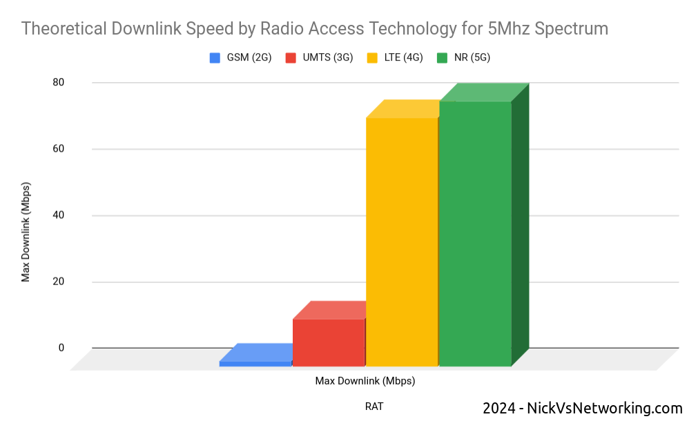
Spectrum is both finite and expensive, so MNOs must find the most efficient way to use that spectrum, to squeeze the most possible value out of it.
In rough numbers, we can say we get 5x the spectral efficiency by moving from 3G to 4G. This means we can carry 5.2x more with the same spectrum on 4G than we can on 3G – A very compelling reason to upgrade.
The like-for-like spectral efficiency of 5G is not significantly greater than that of LTE.
In numbers the same 5Mhz of spectrum we refarmed from UMTS (3G) to 4G (LTE) provided a 5x gain in efficiency to deliver 75Mbps on LTE. The same configuration refarmed to 5G-NR would provide 80Mbps.
Refarming spectrum from 4G (LTE) to 5G (NR) only provides a 6% increase in spectral efficiency.
While 6% is not nothing, if refarmed to a 5G standalone network, the spectrum can no longer be used by LTE only devices (Unless Dynamic Spectrum Sharing is used which in itself leads to efficiency losses), which in itself reduces the efficiency and would add additional load to other layers.
The crazy speeds demonstrated by 5G are not due to meaningful increases in efficiency, but rather the ability to use more spectrum, spectrum that operators need to purchase at auction, purchase equipment to utilize and pay to run.
Claim: 5G Standalone Core is Cheaper to operate as it is “Cloud Native”
It has been widely claimed that the shift for the 5G Core Architecture to being “Cloud Native” can provide cost savings.
Operators should regard this in a skeptical manner; after all, we’ve been here before.
Did moving from big-iron to VNFs provide the promised cost savings to operators?
For many operators the shift from hardware to software added additional complexity to the network and increased the headcount to support this.
What were once big-iron appliances dedicated to one job, that sat in the corner and chugged away, are now virtual machines (VNFs). Many operators have naturally found themselves needing a larger team to manage the virtual environment, compared to the size of the team they needed to just to plug power and data into a big box in an exchange before everything was virtualized.
Introducing a “Cloud Native” Kubernetes layer on top of the VNF / virtualization layer, on top of the compute layer, leaves us with a whole lot of layers. All of which require resources to be maintain, troubleshoot and kept running; each layer having associated costs for staffing, licensing and support.
Many mid size enterprises rushed into “the cloud” for the promised cost savings only to sheepishly admit it cost more than the expected.
Almost none of the operators are talking about running these workloads in the public cloud, but rather “Private Clouds” built on-premises, using “Cloud Native” best practices.
One of the central arguments about cloud revolves around “elastic scaling” where the network can automatically scale to match demand; think extra instances spun up a times of peak demand and shut down when the demand drops.
I explain elastic scaling to clients as having to move people from one place to another. Most of the time, I’m just moving myself, a push bike is fine, or I’ve got a 4 seater car, but occasionally I’ll need to move 25 people and for that I’d need a bus.
If I provide the transportation myself, I need to own a bike, a car and a bus.
But if use the cloud I can start with the push bike, and as I need to move more people, the “cloud” will provide me the vehicle I need to move the people I need to move at that moment, and I’ll just pay for the time I need the bus, and when I’m done needing the bus, I drop back to the (cheaper) push bike when I’m not moving lots of people.
While telecom operators are going to provide the servers to run this in “On-prem-cloud”, they need to dimension for the maximum possible load. This means they need to own a bike/car/bus, even if they’re not using it most of the time, and there’s really no cost savings to having a bus but not using it when you’re not paying by the hour to hire it.
Infrastructure aside, introducing a Standalone 5G Core adds another core network to maintain. Alongside the Circuit Switched Core (MSC/GGSN/SGSN) serving 2G/3G subscribers, Evolved Packet Core serving 4G (LTE) and 5G-NSA subscribers, adding a 5G Standalone Core to for the 5G-SA subscribers served by the 5G SA cells, is going to be more work (and therefore cost).
While the majority of operators have yet to turn off their 2G/3G core networks, introducing another core network to run in parallel is unlikely to lead to any cost savings.
Claim: Upgrading now can save money in the Future / Future Proofing
Life cycles of telecommunications are two fold, one is the equipment/platform life cycle (like the RAN components or Core network software being used to deliver the service) the other is the technology life cycle (the generation of technology being used).
The technology lifecycles in telecommunications are vastly longer than that for regular tech.
GSM (2G) was introduced into the UK in 1991, and will be phased out starting in 2033, a 42 year long technology life cycle.
No vendor today could reasonably expect the 5G hardware you deploy in 2024 to still be in production in 2066 – The platform/equipment life cycle is a lot shorter than the technology life cycle.
Operators will to continue relying on LTE (4G) well into the late 2030s.
I’d wager that there is not a single piece of equipment in the Vodafone UK GSM network today, that was there in 1991. I’d go even further to say that any piece of equipment in the network today, didn’t even replace the 1991 equipment, but was probably 3 or 4 generations removed from the network built in 1991.
For most operators, RAN replacements happen between 4 to 7 years, often with targeted augmentation / expansion as needed in the form of adding extra layers / sectors between these times.
The question operators should be asking is therefore not what will I need to get me through to 2066, but rather what will I need to get to 2030?
The majority of operators outside the US today still operate a 2G or 3G network, generally with minimal bandwidth to support legacy handsets and devices, while the 4G (LTE) network does most of the heavy lifting for carrying user traffic. This is often with the aid of an additional 5G-NSA (Non-Standalone) layer to provide additional capacity.
Is there a cost saving angle to adding support for 5G-Standalone in addition to 2G/3G/4G (LTE) and 5G (Non-Standalone) into your RAN?
A logical stance would be that removing layers / technologies (such as 2G/3G sunsetting) would lead to cost savings, and adding a 5G Standalone layer would increase cost.
All of the RAN solutions on the market today from the major vendors include support for both Standalone 5G and Non Standalone, but the feature licensing for a non-standalone 5G is generally cheaper than that for Standalone 5G.
The question operators should be asking is on what timescale do I need Standalone 5G?
If you’ve rolled out 5G-NSA today, then when are you looking to sunset your LTE network? If the answer is “I hope to have long since retired by that time”, then you’ve just answered that question and you don’t need to licence / deploy 5G-SA in this hardware refresh cycle.
Other Cost Factors
Roaming: The majority of roaming traffic today relies on 2G/3G for voice. VoLTE roaming is (finally) starting to establish a foothold, but we are a long way from ubiquitous global roaming for LTE and VoLTE, and even further away for 5G-SA roaming. Focusing on 5G roaming will enable your network for roaming use by a miniscule number of operators, compared to LTE/VoLTE roaming which covers the majority of the operators in the developed world who can utilize your service.
I decided to split this into 3 posts, next I’ll post the “5G can make us more money” post and finally a “5G because we have to” post. I’ll post that on LinkedIn / Twitter / Mailing list, so stick around, and feel free to trash me in the comments.
I got an email the other day asking a simple question:
How do I know if a subscriber is VoLTE roaming or not when they send an SMS to charge for it?
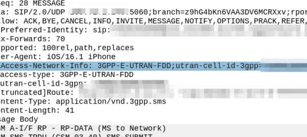
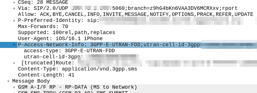
My immediate reaction was to look at the SIP headers, P-Access-Network-Info will tell you where the subscriber is located, end of.
Right?
Well not quite, this will tell the SMSc the location of the subscriber sending the SMS. If the PLMN in the P-Access-Network-Info != the home PLMN, the sub is roaming.
But does this information get passed to the OCS / OFCS?
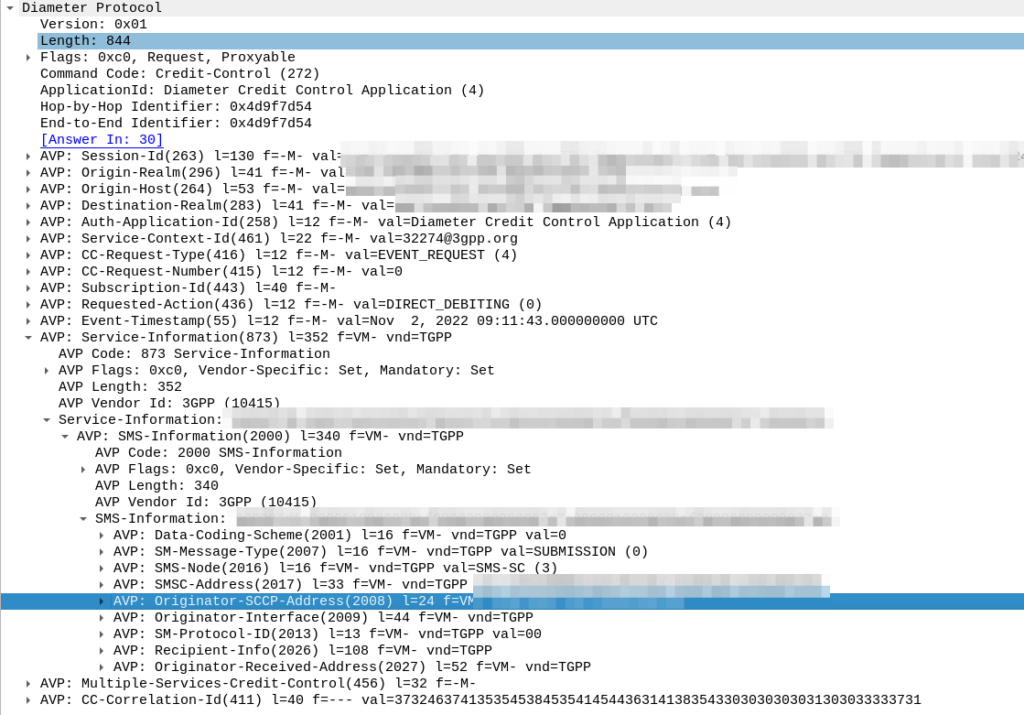
The SMSc uses “Event based charging” to perform credit control, so let’s have a look at what AVPs are present in the Credit Control Request from the SMSc:
Hmm, the SMS-Information AVP (2000) contains a bunch of information about the SMS being sent, but I don’t see anything about the location of the sender in there.
Originator-Interface is just set to “SIP”, of course in a 2G/3G roaming scenario the Originator-SCCP-Address would be that of the Visited PLMN, but for us it is our SCCP address.
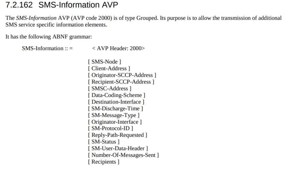
Maybe the standard allows for an additional optional AVP in the SMS-Information-AVP we’re missing? Let’s check TS 32.299:
Nope.
So how to deal with this?
While the standards aren’t totally clear on this, we added an IMS-Info AVP and inside that populated the Access-Network-Information directly from the SIP header, and then picked that off inside our OCS in order to apply the correct rules.
Slicing has long been held up as one of the monetizations opportunities for residential customers, but few seem to be familiar with it beyond a concept, so I thought I’d take a look at how it actually works in Android, and how an end user would interact with it.
For starters, there’s a little used hook in Android TelephonyManager called purchasePremiumCapability, this method can be called by a carrier’s self care app.
Operators would need the Telephony Permission for their app, and a function from the app in order to activate this, but it doesn’t require on Android Carrier Privileges and a matching signature on the SIM card, although there’s a lot of good reasons to include this in your Android Manifest for a Carrier Self-Care app.
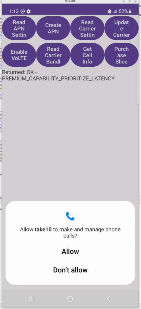
We’ve made a little test app we use for things like enabling VoLTE, setting the APNs, setting carrier config, etc, etc. I added the Purchase Slice capability to it and give it a shot.
And the hook works, I was able to “purchase” a Slice.
I did some sleuthing to find if any self-care apps from carriers have implemented this functionality for standards-based slicing, and I couldn’t find any, I’m curious to see if it takes off – as I’ve written about previously slicing capabilities are not new in cellular, but the attempt to monetise it is.