Polarization Basics
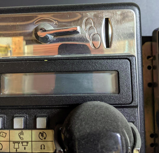
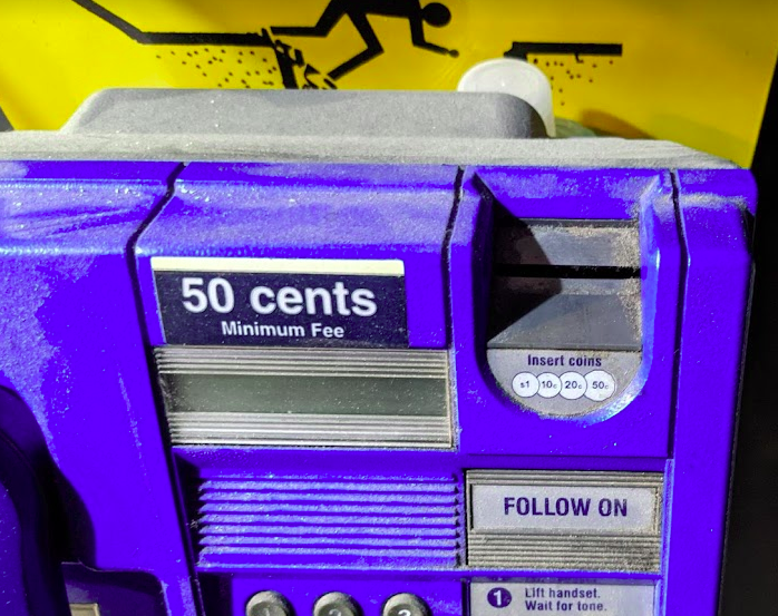
Let’s imagine the coin slot on a payphone – Coins can only enter the slot if they’re aligned with the slot.
If you tried to rotate the coin by 90 degrees, it wouldn’t fit it in the slot.
If the slot on the payphone went from up-to-down, our coin slot could be described as “vertically polarized”.
Only coins in the vertically polarized orientation would fit.
Likewise, a payphone with the coin slot going side-to-side we could describe the coin slot as being “horizontally polarized”, meaning only coins that are horizontally polarized (on their side) would fit into the coin slot.
RF waves also have a polarization, like our coin slot.
A receiver wishing to receive into signals transmitted from a vertically-polarized antenna, will need to use a vertically-polarised antenna to pick up the signal.
Likewise a signal transmitted from a horizontally polarized antenna, would require a horizontally polarised antenna on the receiving side.
If there is a mismatch in polarization (for example RF waves transmitted from a horizontal polarized antenna but the receiver is using a vertically polarized antenna) the signal may still get through, but received signal strength would be severely degraded – in the order of 20dB, which is 1/100th of the power you’d get with the correct polarization.
You can think of polarization mismatches as like cutting up the coin to fit sideways through the coin slot – you’d get a sliver of the original coin that was cut up to fit. Much like you recieve a fraction of the original signal if your polarization doesn’t match on both ends.
Useless Information: In Australia country TV stations and metro TV stations sometimes transmitted different programming. To differentiate the signals on the receiver side, country TV transmitters used vertical polarisation, while metro transmitters used horizontal polarization.
The use of different polarization orientation cuts down on interference in the border areas that sit in the footprint of the metro and country transmitters.
This means as you drive through metro areas you’ll see all the yagi-antennas are horizontally oriented, while in country areas, they’re vertically oriented.
Vertical Polarization
Early mobile phone networks used Vertical Polarization.
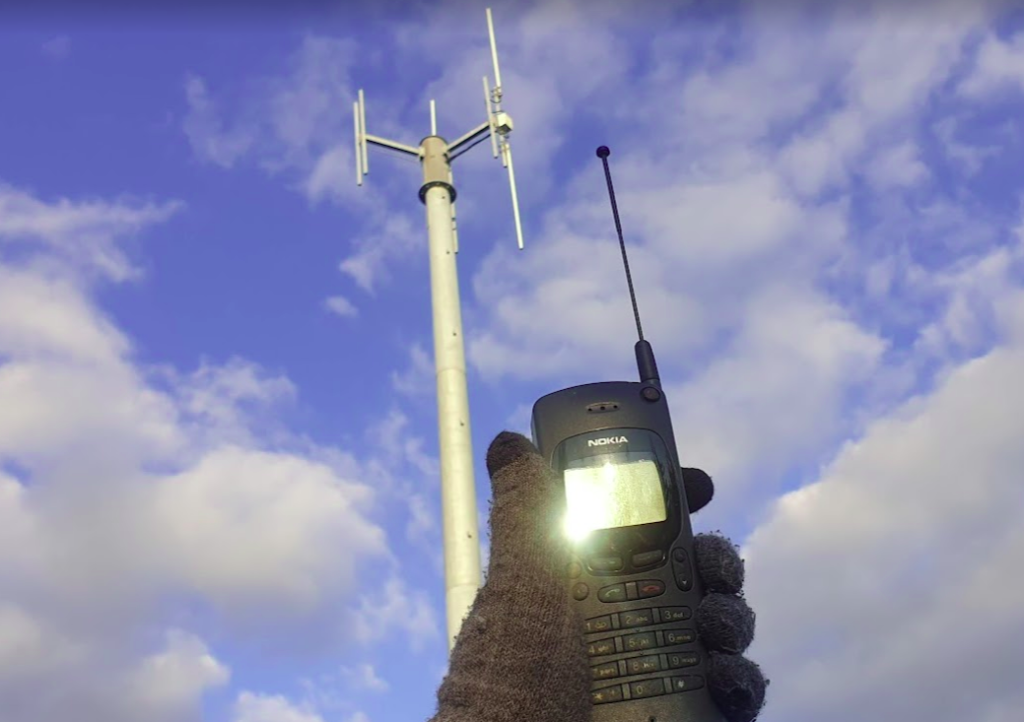
This means they used an flagpole like antenna that is vertically oriented (Omnidirectional antenna) on the base-station sites.
Oldschool mobile phones also had a little pop out omnidirectional antenna, which when you held the phone to your ear, would orient the antenna vertically.
This matches with the antenna on the base station, and away we go. You still sometimes see vertical polarization in use on base-station sites in low density areas, or small cells.
Increasing subscriber demand meant that operators needed more capacity in the network, but spectrum is expensive. As we just saw a mismatch in polarization can lead to a huge reduction in power, and maybe we can use that to our advantage…
Shannon-Hartley Theorem
But first, we need to do some maths…
Stick with me, this won’t be that hard to understand I promise.
There are two factors that influence the capacity of a network, the Bandwidth of the Channel and the Signal-to-Noise Ratio.
So let’s look at what each of these terms mean.
Bandwidth
Bandwidth is the information carrying capacity.
A one-page sheet of A4 at 12 point font, has a set bandwidth. There’s only so much text you can fit on one A4 sheet at that font size.
We can increase the bandwidth two ways:
Option 1 to Increase Bandwidth: Get a larger transmission medium.
Changing the size of the medium we’re working with, we can increase how much data we can transfer.
For this example we could get a bigger sheet of paper, for example an A3 sheet, or a billboard, will give us a lot more bandwidth (content carrying capability) than our sheet of A4.
Option 2 to Increase Bandwidth: Use more efficient encoding
As well as changing the size of the medium we are using, we can change how we store the data on the paper, for example, shrinking the font size to get more text in the same area, which also the bandwidth.
In communications networks this is also true: Bandwidth is determined by how much spectrum we have to work with (For example 10Mhz), and how we encode the data on that spectrum, ie morse-code, Binary-Phase-Shift-Keying or 16-QAM.
Each of the different encoding schemes have different levels of bandwidth for the same amount of spectrum used, and we’ll cover those in more detail in the future.
So now we’ve covered increasing the bandwidth, now let’s talk about the other factor:
Signal-to-Noise Ratio
Signal-to-Noise Ratio (SNR) is the ratio of good signal, to the background noise.
On the train my headphones on block out most of the other sounds.
In this scenario, the signal (the podcast I’m listening to on the headphones) is quite high, compared to the noise (unwanted sounds of other people on the train), so I have a good Signal-to-Noise ratio.
When we talk about the Signal-to-Noise Ratio, we’re talking about the ratio of the signal we want (podcast) to the noise (signal we don’t want).
When I’m on the train if 90% of what I hear is the podcast I’m listening to (the “signal”) and 10% is random background sounds (the “noise”) then my signal-to-noise-ratio is really good (high).
Capacity and SNR
Let’s continue with the listening to a podcast analogy.
The average human talks about 150 words per minute. So let’s imagine I’m listening to a podcast at 150 words per minute.
If I’m listening in an anechoic chamber, then I’ll be able to hear everything that’s being said, so my bandwidth will 150 words per minute. As there is no background noise, my capacity will also be 150 words per minute.
But if I leave an anechoic chamber (much as I love spending time in anechoic chambers), and go back on the train, I won’t hear the full 150 words per minute (bandwidth) due to the noise on the train drowning out some of the signal (podcast).
The Shannon-Hartley Theorem, states that the capacity is equal to the bandwidth multiplied by the signal to noise ratio.
So on the train hearing 90% of what’s said on the podcast, 10% drowned out, means my signal-to-noise ratio is 0.9 (pretty good).
So according to Shannon-Hartley Theorem the capacity of me listening to a podcast on the train (150 words per minute of bandwidth multiplied by 0.9 Signal-to-Noise Ratio) would give me 135 words per minute of capacity.

How this applies to RF Networks
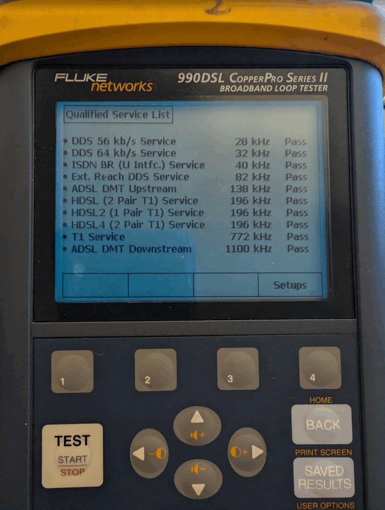
In an RF context, our Bandwidth has a fixed information carrying capacity, for example on LTE, with a 5Mhz wide channel using 16QAM has 12.5Mbps of bandwidth available.
In a simple system, we have two levers we can pull to increase the bandwidth:
- Increasing the size of the channel – If we went from a 5Mhz wide channel to a 20Mhz channel, this would give us 4x the available Bandwidth (Actually slightly more in LTE, but whatever)
- Changing the encoding to cram more data on the same a size channel (From 16QAM to 64QAM would also give us 4x the available Bandwidth).
As we’ll see later in this post, there are some extra tricks (MIMO and Diversity) that we’ll look at later in this post, to increase the bandwidth of the system.
Our Signal-To-Noise (SNR) is constantly variable with a gazillion things that can influence the result.
Some of the key factors that impact the SNR are the distance from the transmitter to the receiver and anything blocking the path between them (trees, buildings, mountains, etc), but there’s so many other factors that go into this. From atmospheric conditions, flat surfaces the signal can reflect off leading to multipath noise, other nearby transmitters, etc, can all influence our SNR.
Our capacity is equal to our Bandwidth multiplied by the Signal-to-Noise ratio.
Shannon-Hartley Theorem (ish)
As a goal we want capacity, and in an ideal world, our capacity would be equal to our bandwidth, but all that noise sneaks in and reduces our available capacity, based on the current SNR value.
So now we want to get more capacity out of the network, because everyone always wants to add capacity to networks.
One trick that we can use it to use multiple antennas with different polarization.
If our transmitter sends the same signal data out multiple antennas, with some clever processing on the transmitter and the receiver, we use this to maximize the received SNR. This is called Transmit Diversity and Receive Diversity and it’s a form of black magic.
The Transmitter uses feedback from the receiver to determine what the channel conditions are like, and then before transmitting the next block of data, compensates for the channel conditions experienced by the receiver, this increases the SNR and allows for higher MCS / encoding schemes, which in turns means higher throughput.
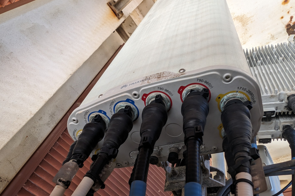
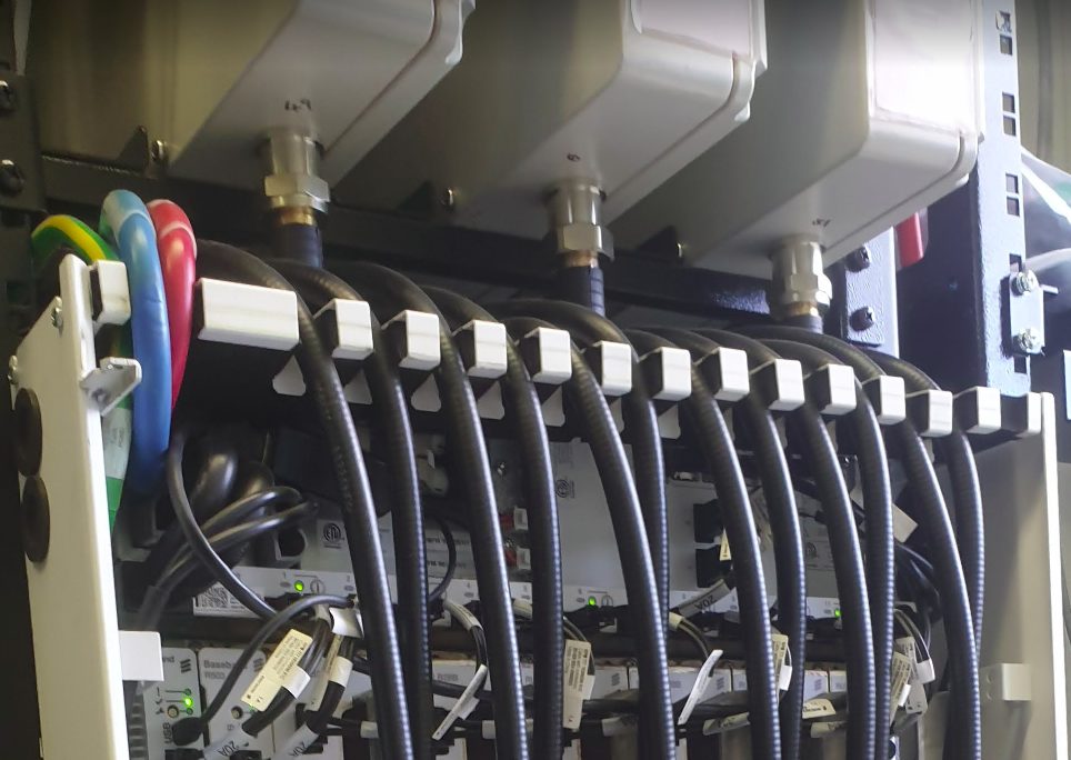
You’ll notice on most Antennas in the wild today you’ve got at least two ports for each frequency, which are + and -, which are the two polarizations.
Modern mobile networks use ±45° slant polarization (aka X Polarization), which works better in the orientations end users hold their phones in.
These two polarizations, each connected to a distinct transmit/receive path on the phone (UE) end and on the base station end, allows multiple data streams to be sent at the same time (spatial multiplexing, the foundation for MIMO) which enables higher throughput or can be configured enable redundancy in the transmission to better pick up weak signals (Diversity).