Preface: I build cellular networks for a job.
We support a network in Alaska, and one of the guys we work with there – John – has a story (which I’ll steal here) where he gets a phone call late at night from someone saying they’re in the US Air Force, and uh, they’ve, uh, lost a plane. And since John works for the phone company, he wouldn’t have any idea where it is would you? They ask him.
As a matter of fact, John could see the last cell the SIM the pilot was carrying was attached to, they sent a helicopter out and found the pilot, who survived.
This was a long time ago, and he was able to pin the location down to a cell (sector), and lookup which direction the sectors were pointing for that cell and the location of it, to give a pretty good idea of the general search area.
Now that everyone carries a GPS in their pockets, the level of accuracy here is a lot more than just which cell are you served by (although that’s a lot of accuracy anyway, and not to be ignored).
There’s significant privacy implications here and a lot of misinformation about pinging cell towers and “zoom enhance” stuff.
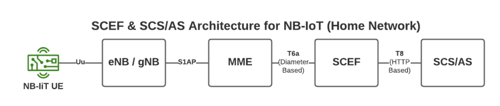
I figured I’d actually share how this works IRL – There’s nothing ‘secret‘ here – All of this stuff is in the 3GPP standards which outline how mobile networks should behave.
I’ve written a precursor to this a few years ago – And the call was coming from… INSIDE THE HOUSE. A look at finding UE Locations in LTE.
Location Sources & Accuracy
There’s roughly 4 levels of accuracy in cell phone networks, we’ll cover each one, and how the network treats it.
(I’m talking 4G/5G here as most of the world has moved on or is already moving on from 2G/3G)
Tracking Area Level Accuracy
Cell sites get grouped into tracking areas, they’re kinda like broadcast domains in TCP/IP networking, when you need to “page” (find) a phone that’s “idle” (sleeping) you page the tracking area.
Tracking Area sizing has sweet spots, you want more than a few cells, commonly about a dozen or so in the same geographic area get lumped into the same tracking area. In regional areas you might have a large geographic area – Up to a few hundred Km in regional Australia for example, lumped into a single tracking area, whereas in a city that might be a single city block.
If you move between cells inside the same tracking area, then your phone doesn’t need to say to the network “hey I’m moving cells” – It’s only if we go over to a new tracking area that the phone needs to wake up and tell the network it’s now in this new tracking area.
(If you’ve got a tracking area that’s too big (too many cells) then it becomes a nightmare to find who you’re looking for, as the paging channels are always blaring out IDs, tracking areas too small and you’ve got phones having to constantly say “hey I’m moving to this tracking area now” – If you want to learn more about Tracking Areas I’ve written about them on the blog before)
The core network (MME/AMF) always knows the location of a phone at minimum to the tracking area – It’s the base level of location the network has to work with.
Cell ID Level Accuracy (CGI / E-CGI)
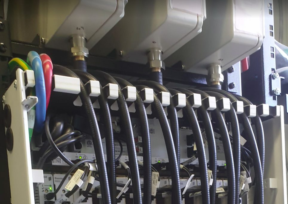
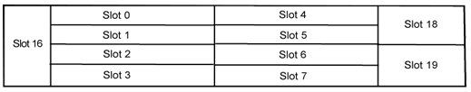
Every cell site sector (cell) has a unique ID to denote which carrier you’re connected to. If you’ve got a 3 sector site, with a single layer per cell sector, then that’s 3 Cell Global Identifiers (CGIs) – one for each sector.
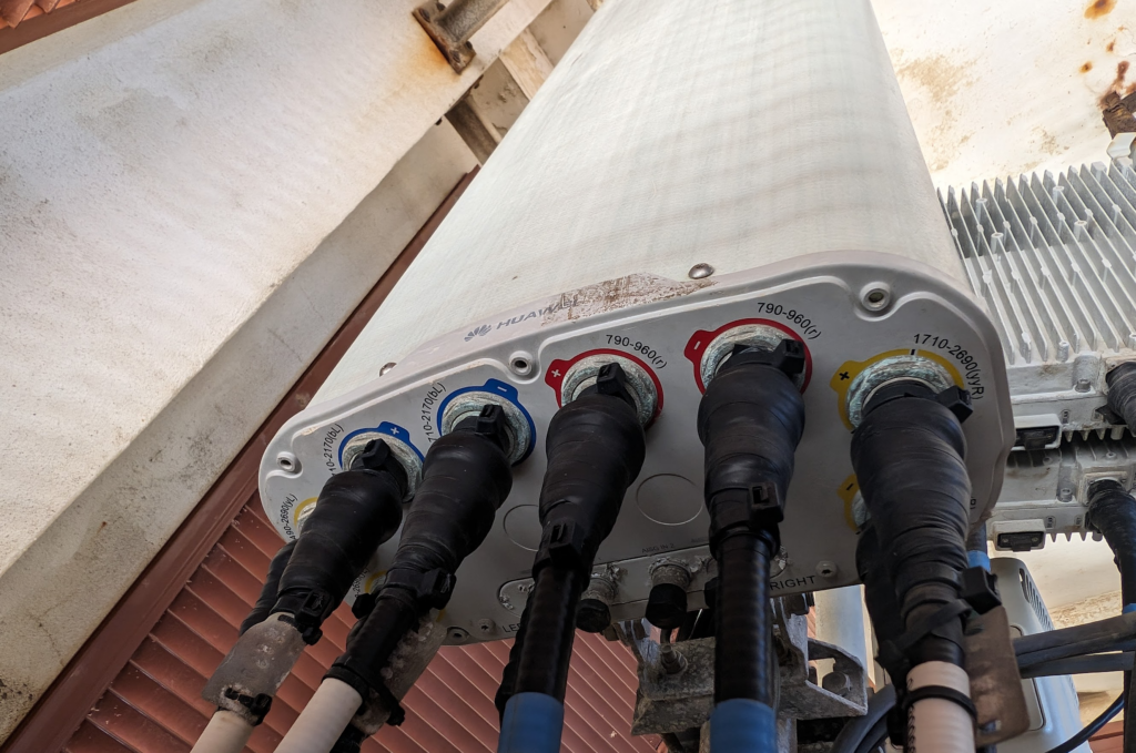
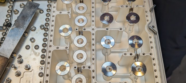
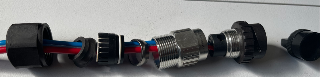
Here’s a tower we put up recently, the CGIs I’ve drawn on are just examples, but if you’re connected to the sector facing North, you’d have CGI of 111, if you’re connected to the cell to the south east, you’d have 112, and the one to the south west would be 113.
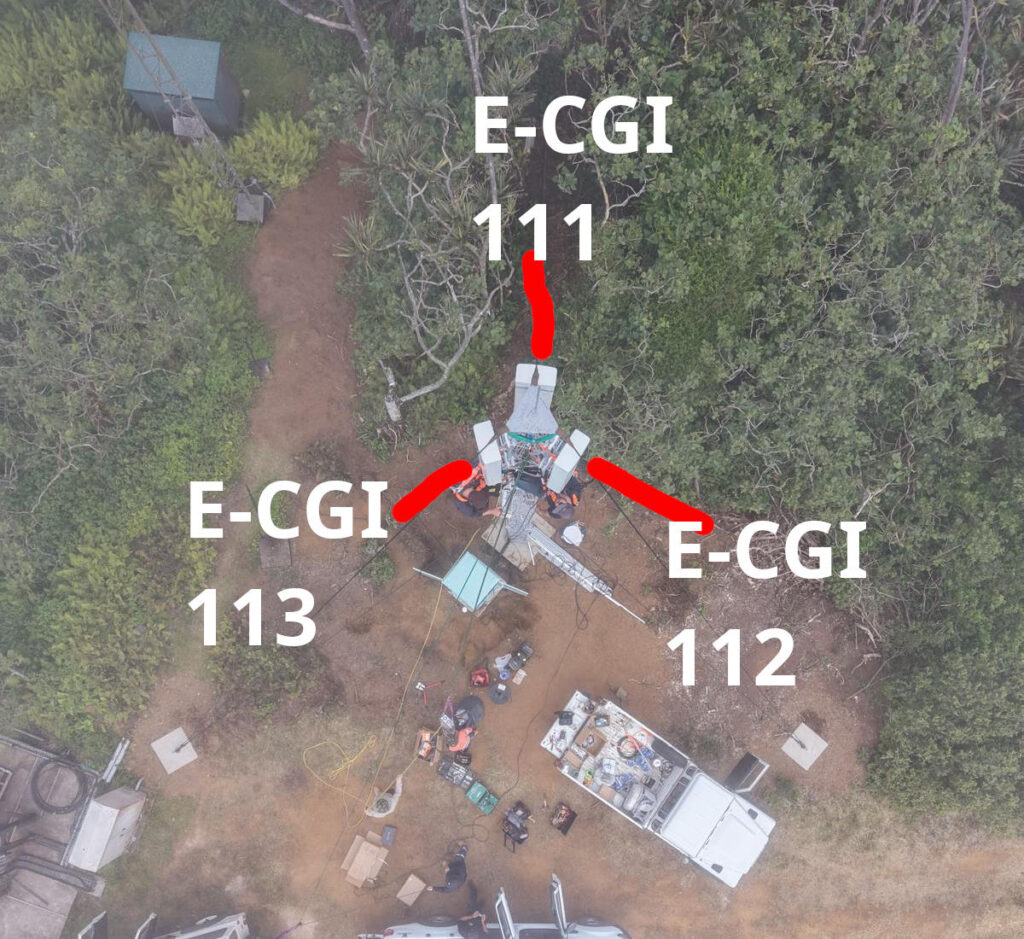
CGIs are just numbers, they could be any number, all that matters is that number is unique (ish) in the network, they don’t need to be sequential, or have any common digits.
If we know the CGI of a given user we can kinda draw a 1/3rd wedge off the side of the tower in the direction the antenna is pointing, and if you’re inside that wedge, and that tower is still providing coverage, then we know the customer is somewhere inside that wedge.
But those wedges can still be large, so the margin of error for locating someone is still pretty large. You can probably answer the question of “Are they in the office or are they at home” if they’re in different suburbs.
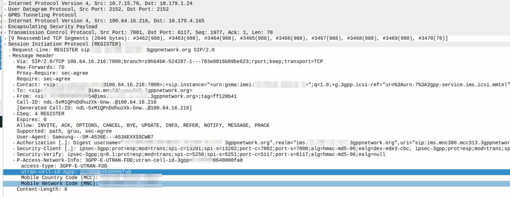
There was a recent case of a misconfigured Mavenir IMS in the O2 network in the UK that was leaking CGI information on calls between two parties, as the SIP messages contained this and were not getting stripped before being passed to the B-Party.
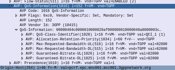
When the network wants to know a bit more about where the phone is located, it can ask the cell site which Global Cell ID the phone is in, this is pretty rare, but can be done. When the phone is actively doing stuff, like making a call, using data or sending a text, the network knows the CGI of the event.
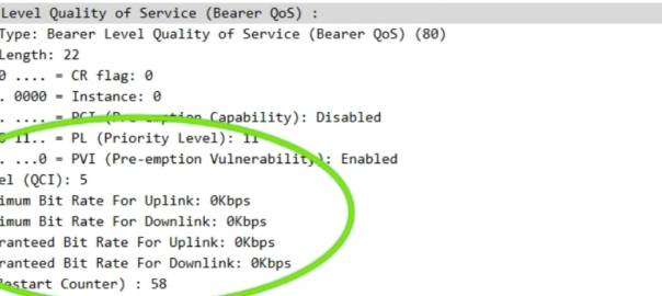
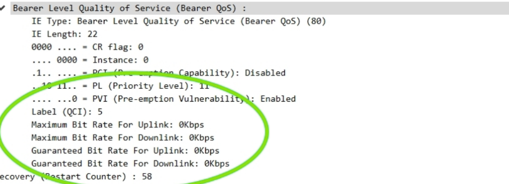
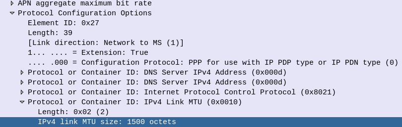
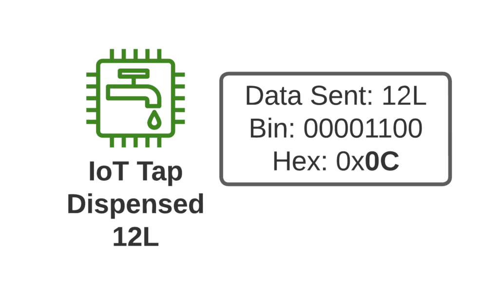
My lab is setup with CGI 4000 and TAC 100, and this information is littered across every signaling message.
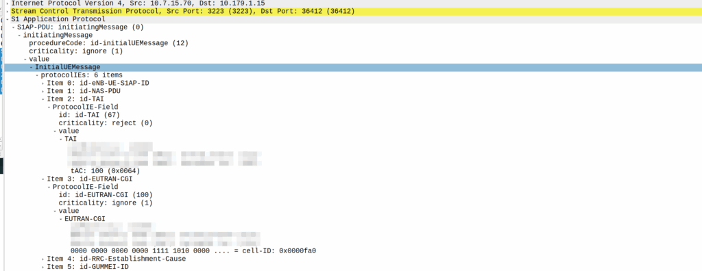
Note: The encoding shows up as 0000 0000 0000 0000 1111 1010 0000 …. = cell-ID: 0x0000fa0 for CGI 4000, just roll with it, the spec explains why this is.
GNSS LPP Positioning
When the Cell ID level is not accurate enough, the network can request the phone to provide it’s location, using whatever it’s got available to it.
In reality, this is either done by an engineer from the phone company with the permissions to do so, or directly by law enforcement using the SLh/SLg Diameter interfaces.
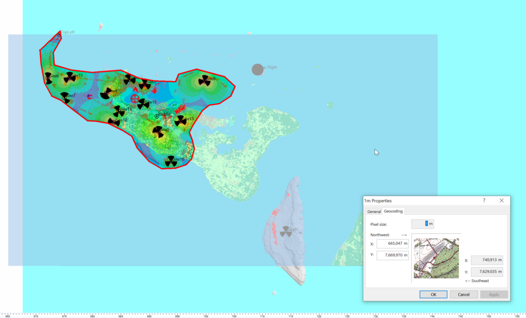
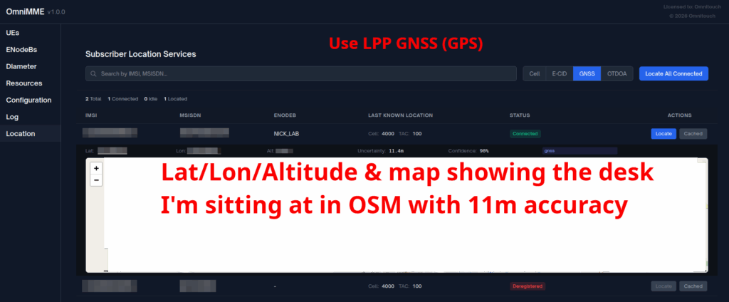
When an engineer does it, there’s usually a portal they can go to, like this one in OmniMME, they search the IMSI or MSISDN, and then can get the location information via a variety of methods.
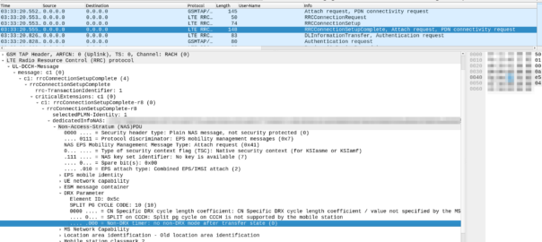
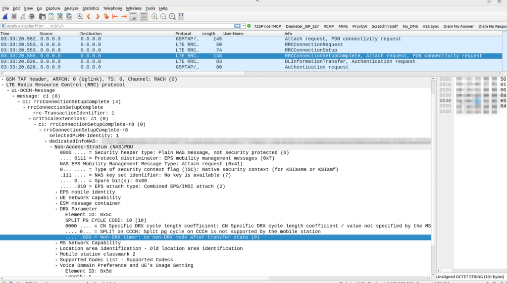
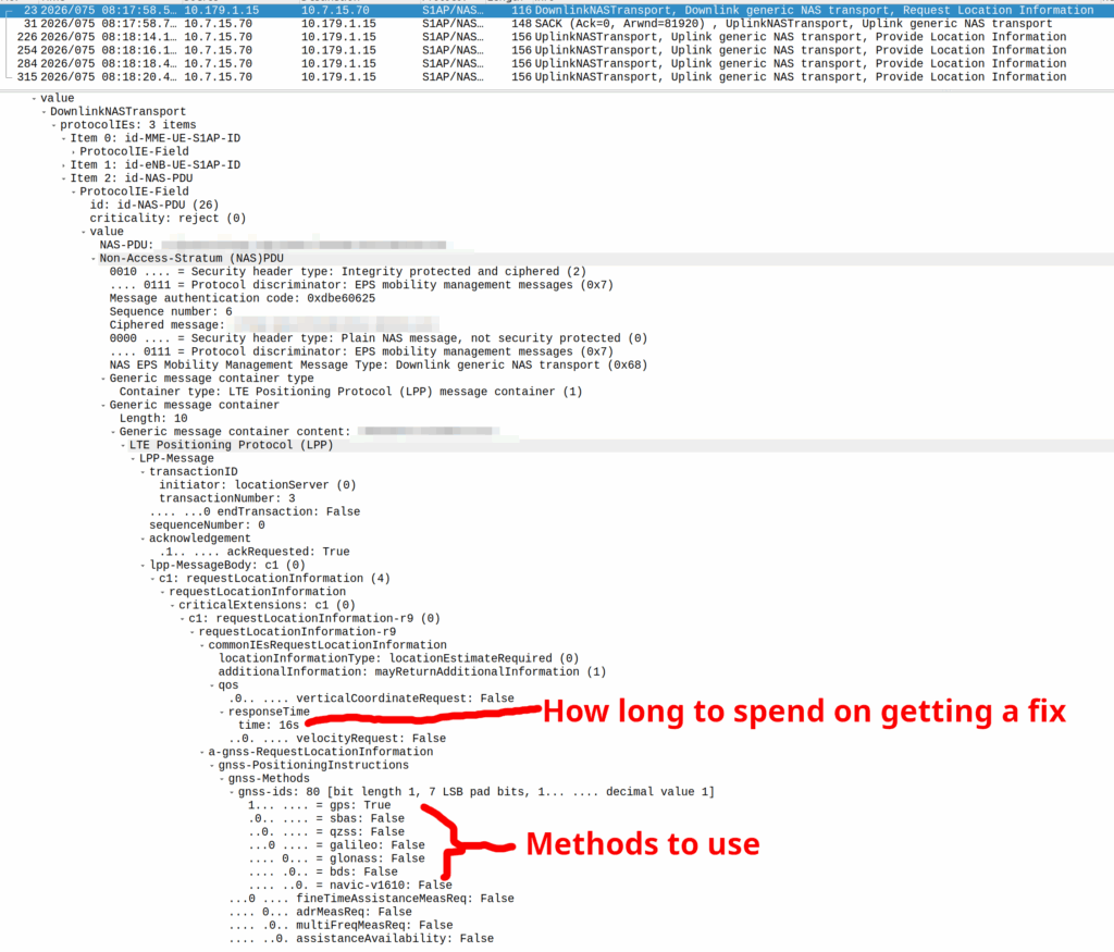
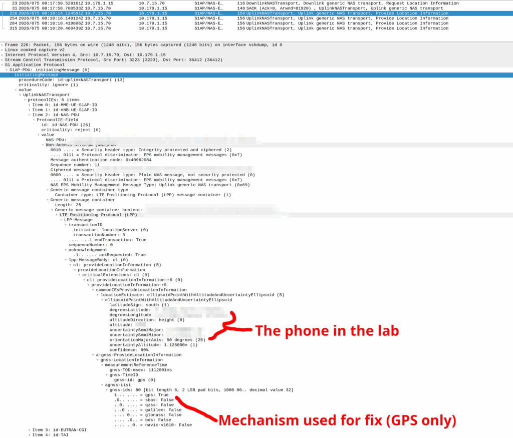
Your phone gets a message from the network, that says “Hey phone, tell me where you are”.
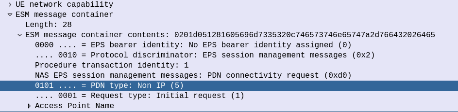
If you’ve got access to RRC messaging / NAS messaging on your phone through QXDM / Diag mode – You can see these requests.
If you’ve got enough access to the baseband you can even block these requests should you feel so inclined.
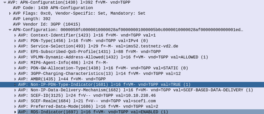
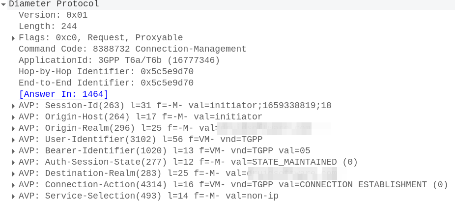
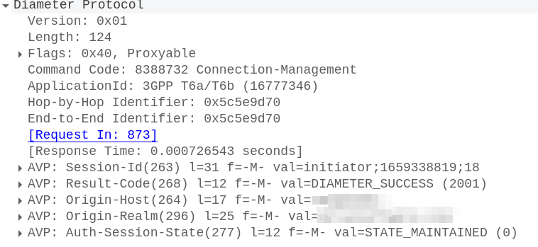
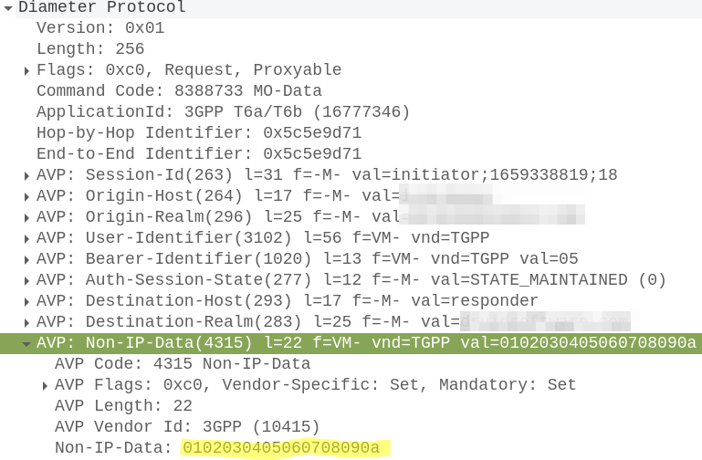
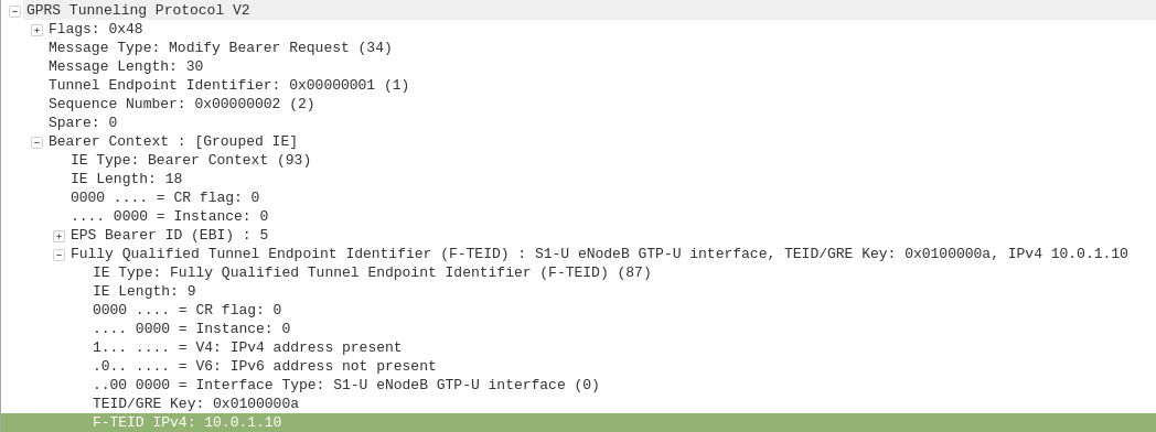
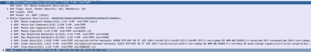
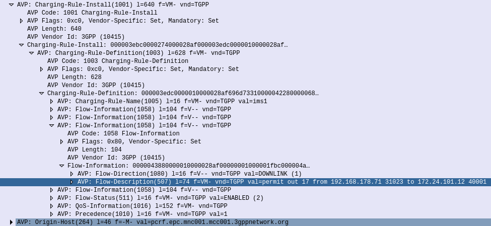
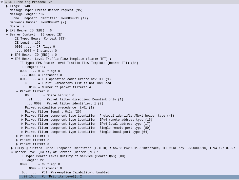
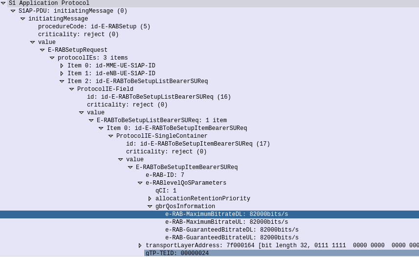
I’ve included some Wireshark captures of how this actually looks and how it looks from the Web UI of the MME, with the address removed.
OTDOA – “Pinging”
Sometimes you don’t get an indoor location with GPS or the phone might be too old to support LPP Positioning, no GPS built in or something.
In those scenarios, we use “Time Difference of Arrival” to calculate the position by measuring time between 2 or more cell sites, and calculating the time between when a signal was sent to a phone, and when it receives it, to calculate distance from the base station.
This is better than CGI as it gives you an idea of how far from the cell site the phone is, and the cell site, but it doesn’t return a map with “you are here”, but rather some rough distances, and CGIs for each cell it can see.
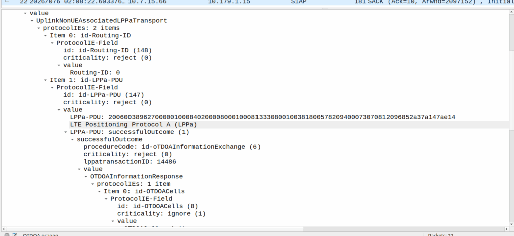
The engineer then pulls up a map of all the cell sites, finds the CGIs the cell phone can see, headings for each CGI and tries to do some early high school maths like someones life actually depends on it.