So it’s the not to distant future and the pundits vision of private LTE and 5G Networks was proved correct, and private networks are plentiful.
But what PLMN do they use?
The PLMN (Public Land Mobile Network) ID is made up of a Mobile Country Code + Mobile Network Code. MCCs are 3 digits and MNCs are 2-3 digits. It’s how your phone knows to connect to a tower belonging to your carrier, and not one of their competitors.
For example in Australia (Mobile Country Code 505) the three operators each have their own MCC. Telstra as the first licenced Mobile Network were assigned 505/01, Optus got 505/02 and VHA / TPG got 505/03.
Each carrier was assigned a PLMN when they started operating their network. But the problem is, there’s not much space in this range.
The PLMN can be thought of as the SSID in WiFi terms, but with a restriction as to the size of the pool available for PLMNs, we’re facing an IPv4 exhaustion problem from the start if we’re facing an explosion of growth in the space.
Let’s look at some ways this could be approached.
Everyone gets a PLMN
If every private network were to be assigned a PLMN, we’d very quickly run out of space in the range. Best case you’ve got 3 digits, so only space for 1,000 networks.
In certain countries this might work, but in other areas these PLMNs may get gobbled up fast, and when they do, there’s no more. New operators will be locked out of the market.
Loaner PLMNs
Carriers already have their own PLMNs, they’ve been using for years, some kit vendors have been assigned their own as well.
If you’re buying a private network from an existing carrier, they may permit you to use their PLMN,
Or if you’re buying kit from an existing vendor you may be able to use their PLMN too.
But what happens then if you want to move to a different kit vendor or another service provider? Do you have to rebuild your towers, reconfigure your SIMs?
Are you contractually allowed to continue using the PLMN of a third party like a hardware vendor, even if you’re no longer purchasing hardware from them? What happens if they change their mind and no longer want others to use their PLMN?
Everyone uses 999 / 99
The ITU have tried to preempt this problem by reallocating 999/99 for use in Private Networks.
The problem here is if you’ve got multiple private networks in close proximity, especially if you’re using CBRS or in close proximity to other networks, you may find your devices attempting to attach to another network with the same PLMN but that isn’t part of your network,
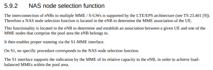
Mobile Country or Geographical Area Codes
Note from TSB
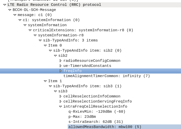
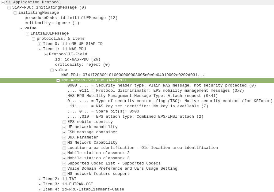
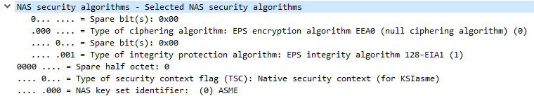
Following the agreement on the Appendix to Recommendation ITU-T E.212 on “shared E.212 MCC 999 for internal use within a private network” at the closing plenary of ITU-T SG2 meeting of 4 to 13 July 2018, upon the advice of ITU-T Study Group 2, the Director of TSB has assigned the Mobile Country Code (MCC) “999” for internal use within a private network.Mobile Network Codes (MNCs) under this MCC are not subject to assignment and therefore may not be globally unique. No interaction with ITU is required for using a MNC value under this MCC for internal use within a private network. Any MNC value under this MCC used in a network has
significance only within that network.The MNCs under this MCC are not routable between networks. The MNCs under this MCC shall not be used for roaming. For purposes of testing and examples using this MCC, it is encouraged to use MNC value 99 or 999. MNCs under this MCC cannot be used outside of the network for which they apply. MNCs under this MCC may be 2- or 3-digit.
(Recommendation ITU-T E.212 (09/2016))
The Crystal Ball?
My bet is we’ll see the ITU allocate an MCC – or a range of MCCs – for private networks, allowing for a pool of PLMNs to use.
When deploying networks, Private network operators can try and pick something that’s not in use at the area from a pool of a few thousand options.
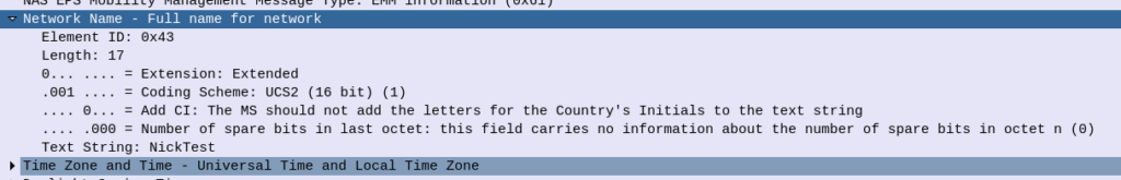
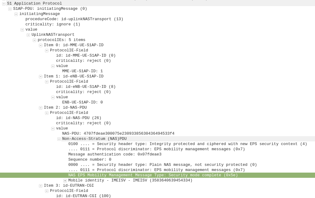
The major problem here is that there still won’t be an easy way to identify the operator of a particular network; the SPN is local only to the SIM and the Network Name is only present in the NAS messaging on an attach, and only after authentication.
If you’ve got a problem network, there’s no easy way to identify who’s operating it.
But as eSIMs become more prevalent and BIP / RFM on SIMs will hopefully allow operators to shift PLMNs without too much headache.