MOCN is one of those great concepts I’d not really come across,
Multi-tenancy on the RAN side of the network, allowing an eNB to broadcast multiple PLMN IDs (MCC/MNC) in the System Information Block (SIB).
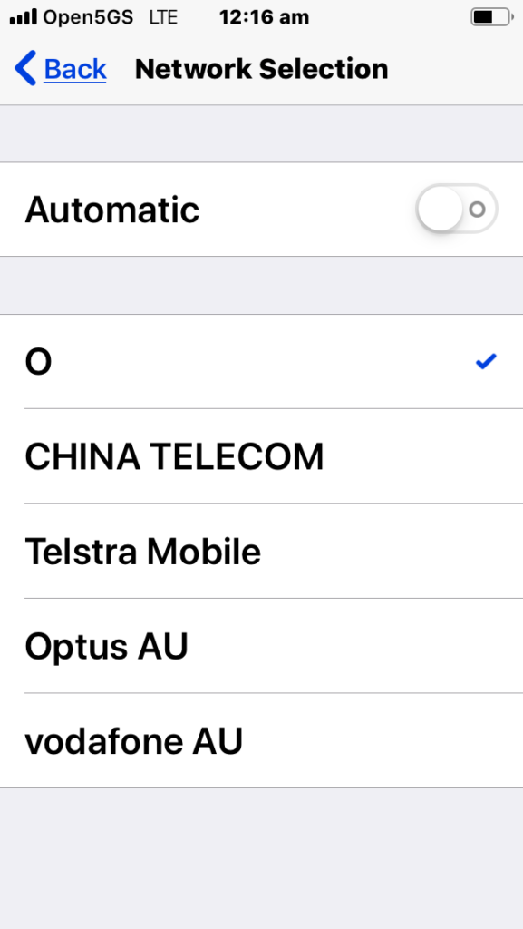
It allows site sharing not just on the tower itself, but site sharing on the RAN side, allowing customers of MNO A to see themselves connected to MNO A, and customers from MNO B see themselves as connected to MNO B, but they’re both connected to the same RAN hardware.
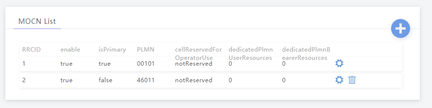
Setup in my lab was a breeze; your RAN hardware will probably be different.
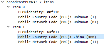
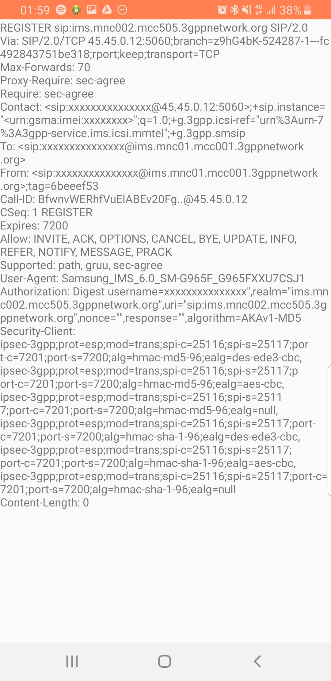
In terms of signaling it’s a standard S1AP Setup Request except with multiple broadcast PLMN keys:
This series of post covers RF Planning using Forsk Atoll. We cover the basics of RF Planning in the process of learning how to use the software.
Forsk Atoll is software for RF Planning and Optimization of mobile networks.
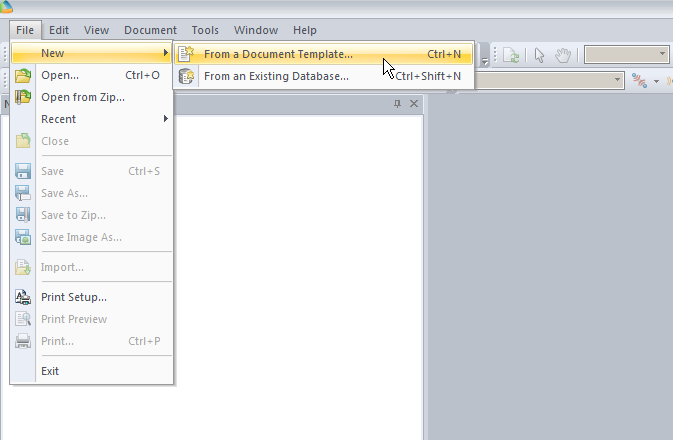
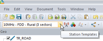
We’ll start by creating a new document from template:
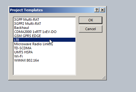
In our example we’re working with LTE, so, we’ll pick the LTE template.
(The templates setup the basic information on what we’re looking at, prediction models and defaults.)
So now we’ll be looking at a blank white document, showing our map, with no data on it, Atoll doesn’t know if the area is hilly, heavily populated, densely treed, what we’re dealing with is a flat void with no features – “flatland” a perfect place to start.
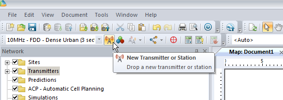
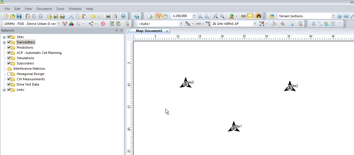
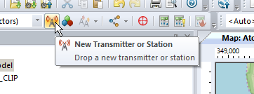
We’ll add an eNodeB (Transmitter Station and Site) from the top menu bar, clicking the transmitter icon to add a new Transmitter or Station.
Now we’ll click in the white of our map to place the transmitter site, and repeat this a few times.
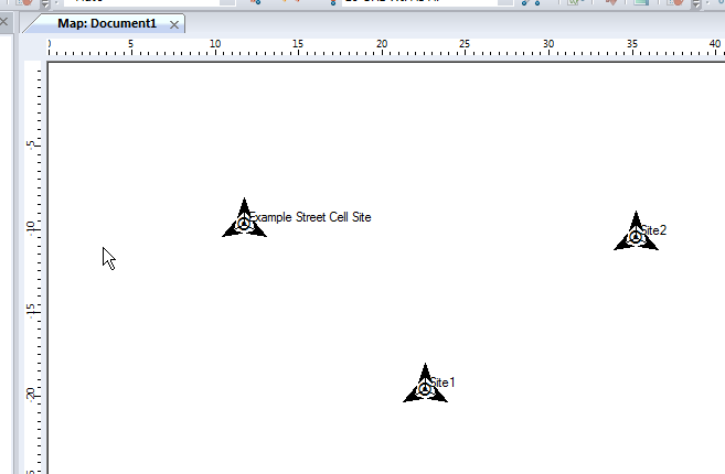
Now we’ve added a few transmitter sites, let’s take a bit of a look at one.
If we take a closer look we’ll see it’s actually created us a 3 sector site, and each of the arrows coming from the site is a cell sector.
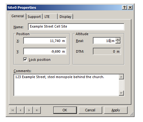
Double clicking on the transmitter will allow us to change the basic info about the site, such as it’s location, as well as display parameters, etc.
In the General tab I’ve renamed Site0 to “Example Street Cell Site”, given it an altitude (for the base of the site) and some comments,
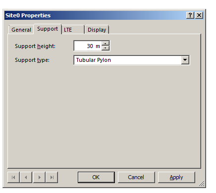
In the Support tab I’ve put some information about the support structure the antennas are one, in our case it’s on a 30m pylon / monopole.
In the LTE tab we can specify S1 throughput (backhaul) and in the Display tab we can set the color / icon used to display this site, but we’ll keep it simple for now and confirm these changes by pressing OK.
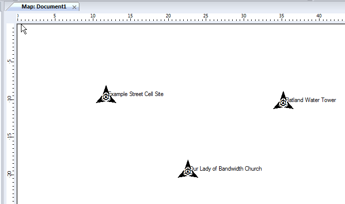
We can give each of our other Transmitters a bit of basic info, again, same process, double click on them and add some info:
So in my example I’ve got 3 transmitter sites, labeled and each given a bit of basic info. The main thing we need to have correct for each site is the location (In our case we’re placing them anywhere so it doesn’t matter), the height of the site (Altitude -Real) and the height of the structure (Support Height) the antennas are on.
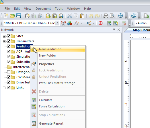
Now we’ve got our 3 cell sites in our imaginary town devoid of any features, let’s get some coverage predictions for the inhabitants of desolate featureless town!
We’ll right click on Predictions and select “New Prediction”,
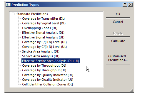
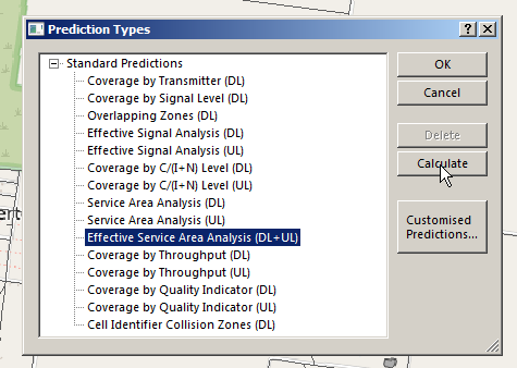
There’s a lot of different prediction types, but let’s look at the Effective Service Area Analysis for Uplink and Downlink from our eNodeBs.
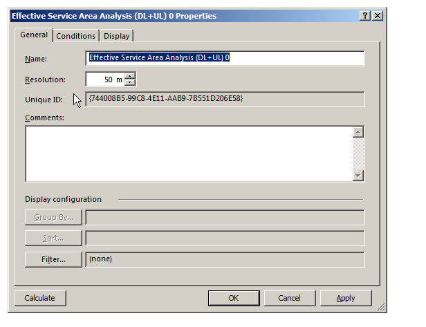
We’ll be asked to give this coverage prediction a name, and also specify a Resolution – The higher the resolution the more processing time but the higher the accuracy calculated.
At 50m it means Atoll will split the map into 50m squares and calculate the coverage in each square. This would be suitable for planning in really rural areas where you want a rough idea of footprint, but for In Building Coverage you’d want far more resolution, so you might want select 5m resolution say.
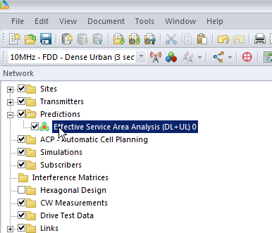
We’ll click Ok and now if we expand “Predictions” we’ll see our catchily named “Effective Service Area Analysis” there.
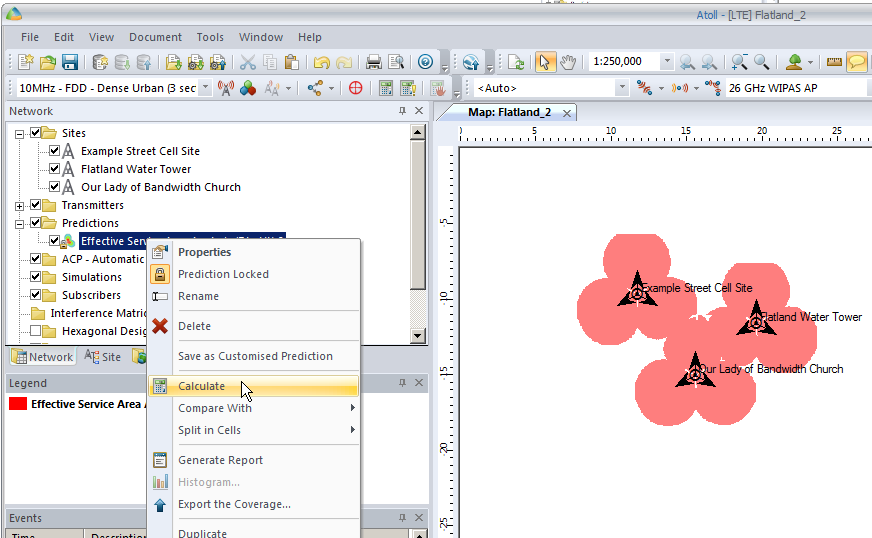
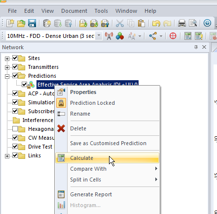
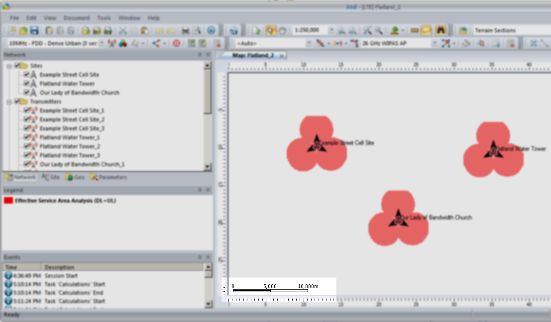
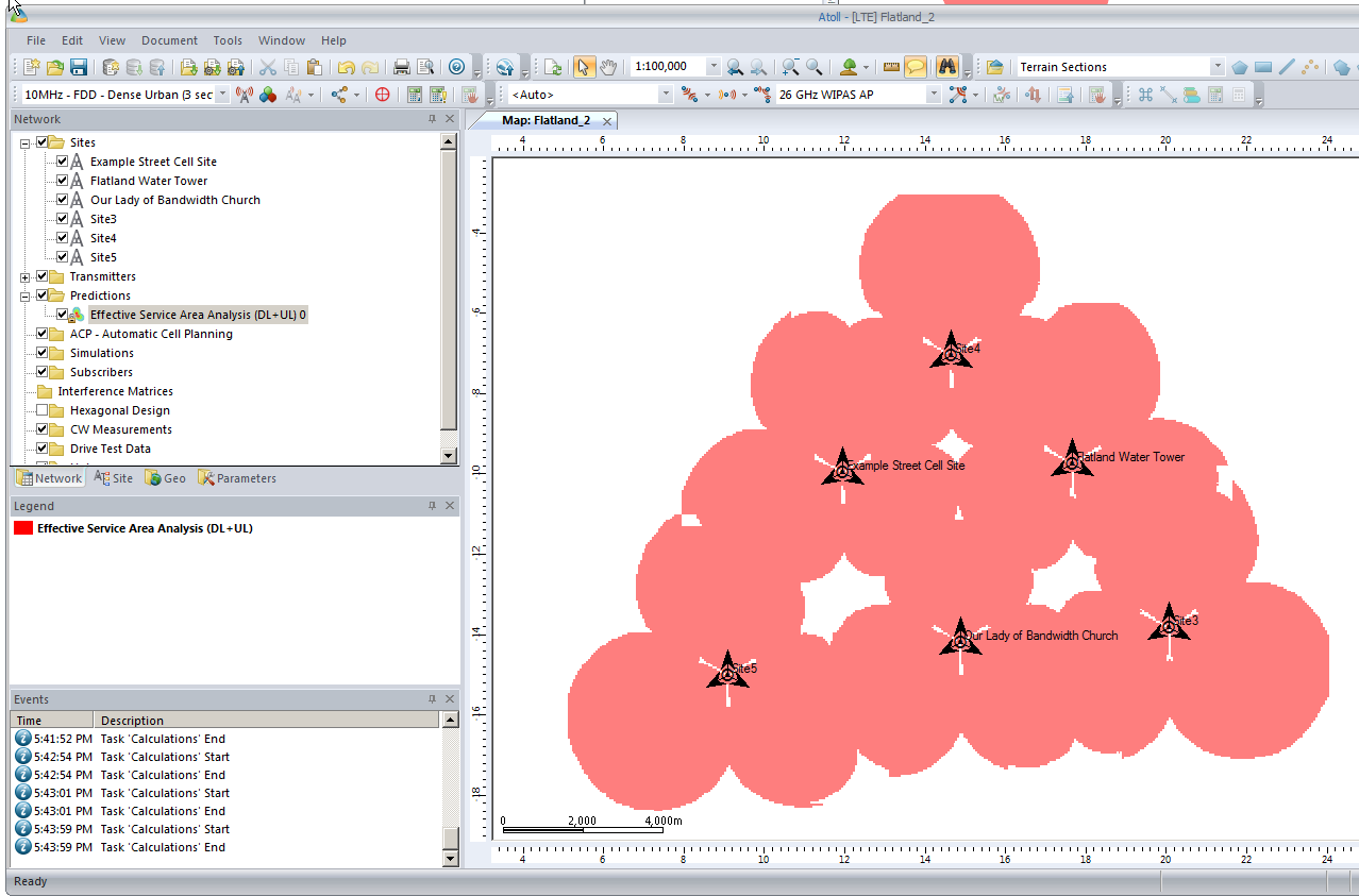
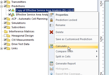
By right clicking on our prediction we can select “Calculate” and presto, we’ll have a prediction of service area from each of our cells,
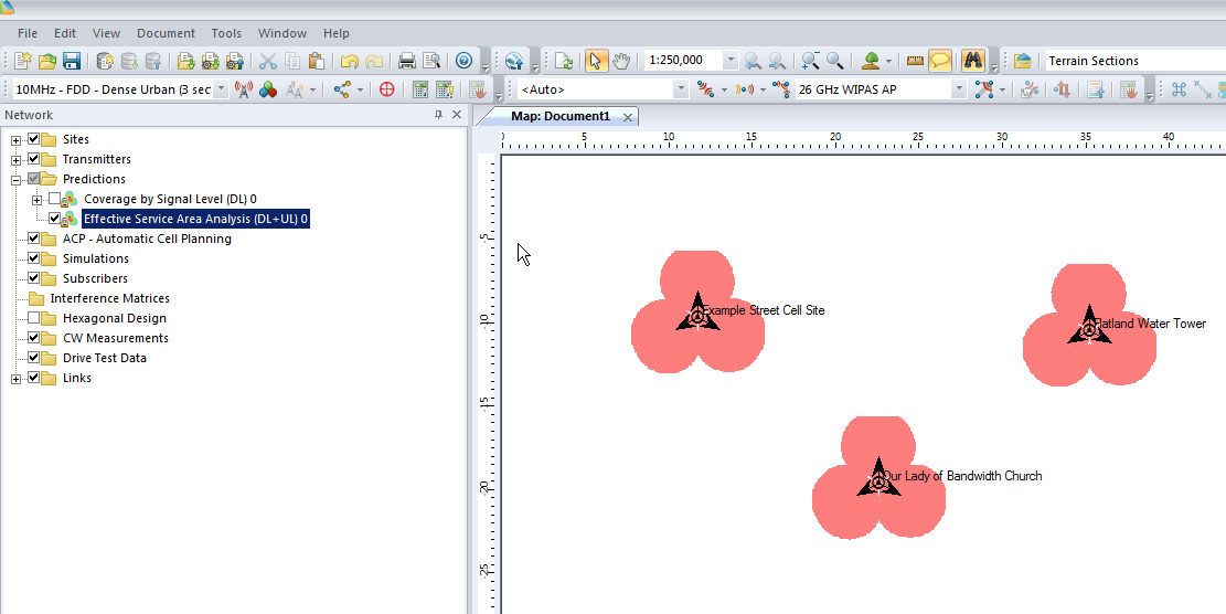
Each of those pink cherry blobs represents the effective usable area of coverage provided by our network.
We may have some unhappy customers looking at this, our users will only be able to use their devices around Fake Street, Flatland Water Tower and the Our Lady of Bandwidth church.
But if we have a look at the scale in the bottom left of the screen that’s understandable, our sites are ~10km apart…
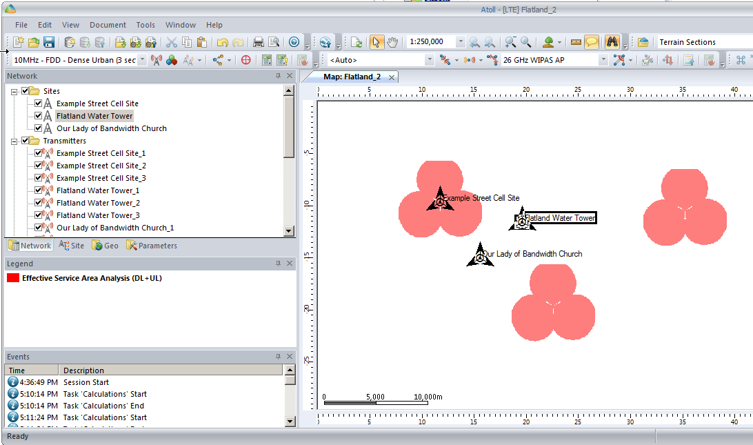
So let’s cheat a little by clicking and dragging on each cell site to bring them closer together, in real life we can’t move sites quite so easily…
You’ll notice our prediction hasn’t changed, so let’s recalculate that by right clicking on our Prediction and selecting Calculate again,
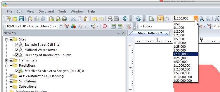
We’ll also set our zoom level from 1:250,000 to something a bit more reasonable like 1:100,000
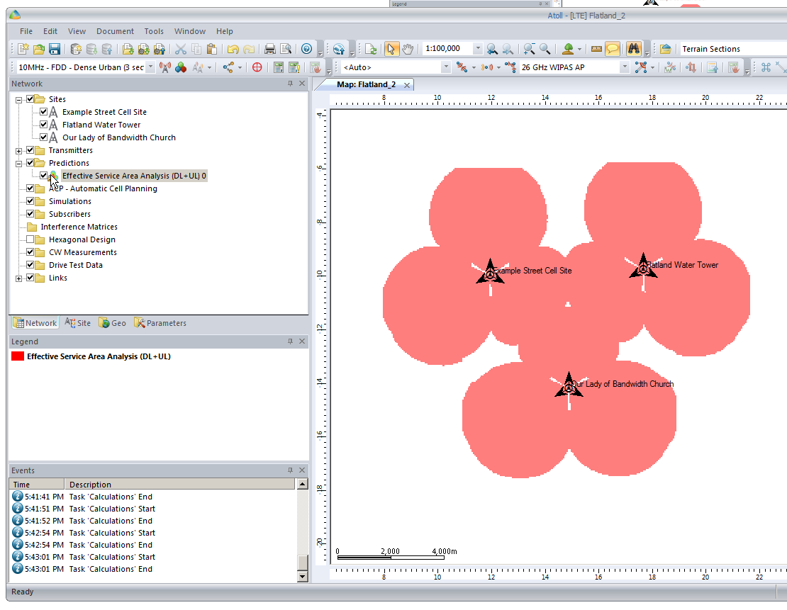
So now our 3 sites have got one area fairly well covered, let’s throw in a few more sites to expand our footprint a bit.
We’ll add extra sites as we did at the start, and fill in those coverage gaps.
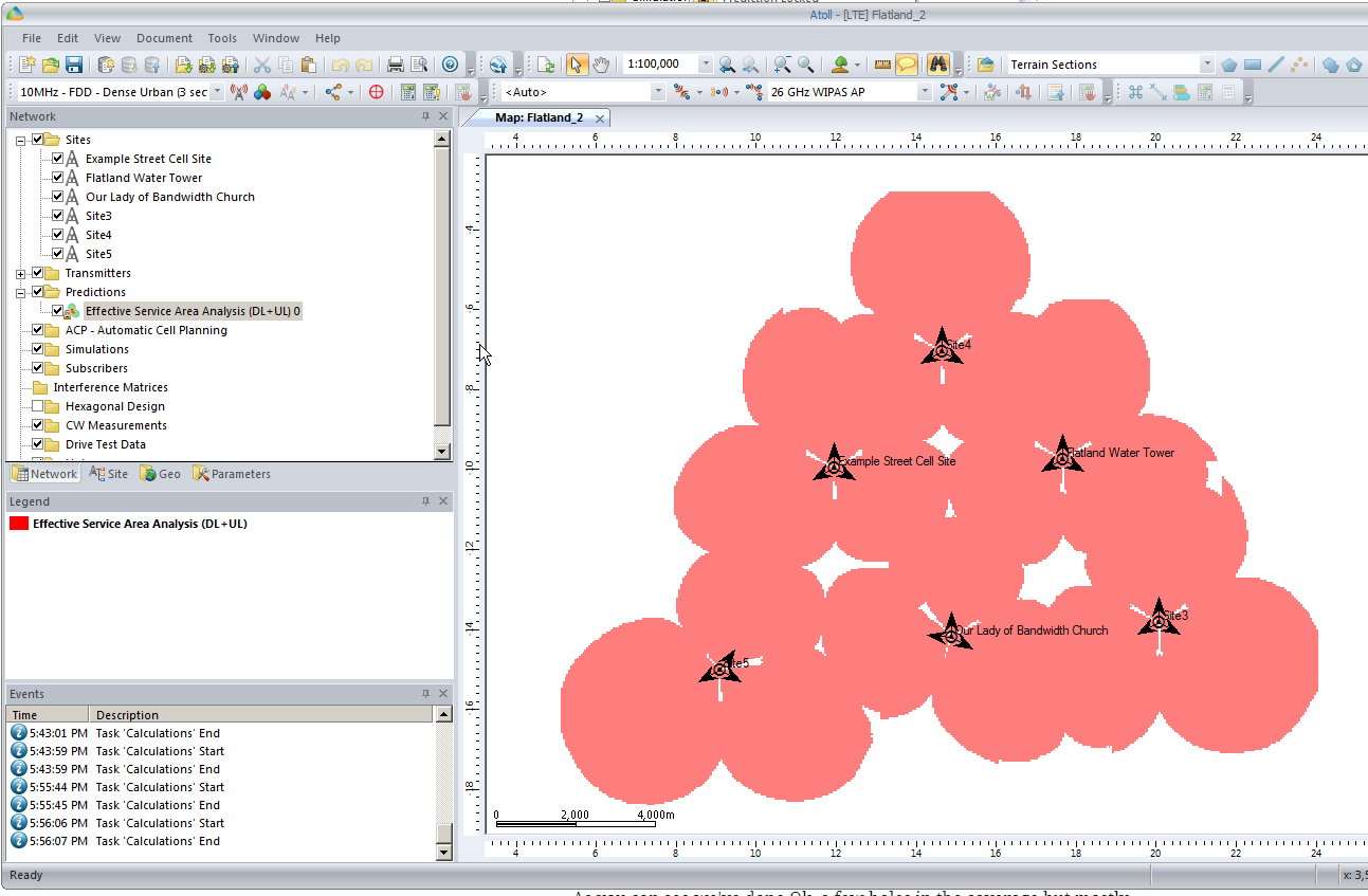
After we’ve added some extra sites we’ll recalculate our Coverage Predictions and have a look at how we’ve done.
As you can see we’ve done Ok, a few holes in the coverage but mostly covered.
So next let’s do some tweaking to try and increase our predicted coverage,
By clicking on a site’s sector we can reorient the antenna to a different angle, by recalculating the coverage prediction we can see how this effects the predicted coverage.
By now you’ve probably got an idea of the basics of what we’re doing in Atoll, how changing the location, orientation and height of cells / sites affects the coverage, and how you can predict coverage.
In the upcoming posts we’ll cover adding real world data to Atoll so we can accurately model and predict how our RAN will perform.
We’ll look at how we can use Automatic Cell Planning to get the most optimal setup in terms of power settings, antenna orientations and tilts, etc for our existing sites.
We’ll be able to simulate subscribers, traffic flow, backhaul, and model our network all before a single truck rolls.
So stick around, the next post will be coming soon and will cover adding environment data.
In our last post we talked about getting our geospatial data right, and in our first post we covered the basics of adding sites and transmitters.
There’s a bit of a chicken-and-egg problem with site placement, antenna orientation, type and down-tilt.
If all our sites were populated and in place, we could look at optimizing coverage by changing azimuths / orientations, plug in our data and run some predictions / modeling and coming up with some solutions. Likewise if we’ve already done that we might want to calculate ideal down-tilt angles to get the most out of network.
But we’ve got no sites, no transmitters and no coverage predictions yet, so we’re probably going to need to ask ourselves a more basic, but harder question: Where will we put the cell sites?
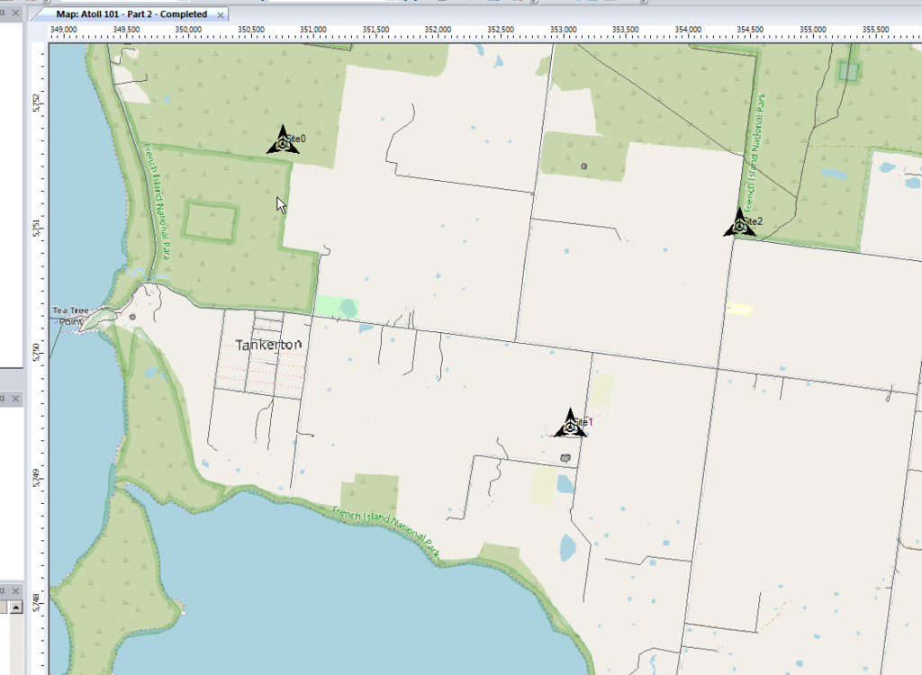
To keep this easy we’ll focus on providing the South Western corner of the Island, a town called Tankerton, with only 3 cell sites.
Manual Site Selection
In the very first post we put up a few sites, we’ll do the same, let’s place 3 sites in the bottom right of the island and attempt to provide contiguous coverage for the town with them;
We’ll pick our Station Template and set it to FDD Rural as this is pretty remote.
Next we’ll add some sites and transmitters:
Click to place it on the map and add our cell sites;
When we’re looking at where to place it, it’s good to remember that height (elevation) is good (To an extent), so when looking at where to place sites, keep an eye on the Z (Height) value in the bottom right, and try and pick sites with a good elevation.
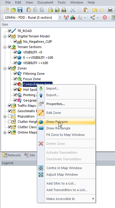
Setting Computation Zone
As we’re only focusing on a small part of the island we’ll set a Computation Zone to limit the calculations / computations Atoll has to do to a set region.
I’ve chosen to draw a Polygon around the area, but you could also just get away with drawing a Rectangle, around the area we’re interested in.
This just constrains everything so we’re only crunching numbers inside that area.
Predictions
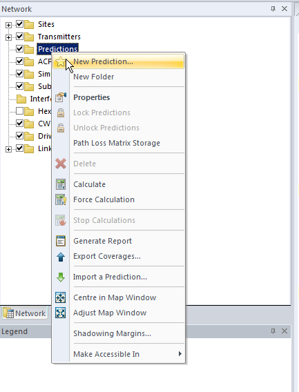
So now we’ve put our 3 sites out & constrained to the Tankerton area, let’s see how much of the area we’ve covered, we’ll jump to the Network tab, right click on Predictions and select New Prediction
There’s a lot of predictions we can run, but we’ll go simple and select Effective Service Area Analysis (UL + DL) & click Calculate
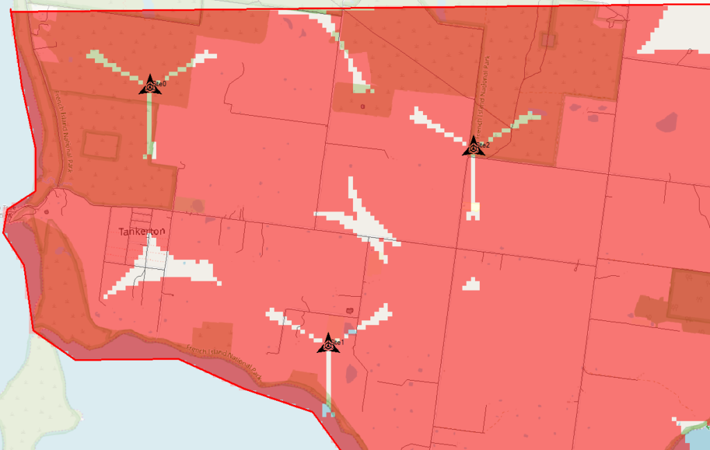
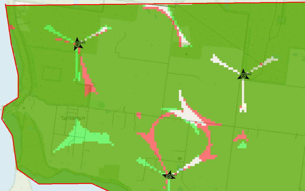
Atoll will crunch the numbers and give us a simple overlay, showing the areas with and without coverage.
The areas in red are predicted to have coverage, and the areas with no shading will be our blackspots / “notspots”.
We’ve covered most of the area, but we can improve.
Manually Tweaking Attributes
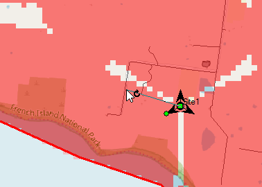
So there’s still some holes in our coverage, so let’s adjust the azimuth of some of the antennas and see if we can fill them.
Click on each of the arrows on the site, each of these represents an antenna / cell and we can change the angles.
So after a bit of fiddling I think I’ve got a better antenna azimuth for each of the sectors on each of my 3 sites.
Let’s compare that to what we had before to see if we’ve made it better or worse,
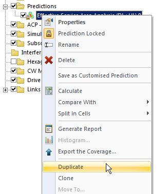
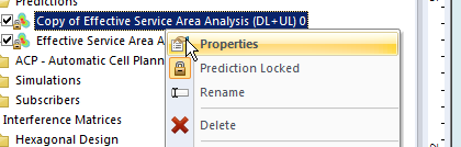
We’ll Duplicate the Effective Service Area Analysis prediction we created before & calculate it.
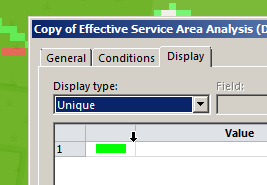
To make viewing a bit easier we’ll edit the properties of the copy and set it to a different colour:
Now I can see at a glance how much better we’re looking;
The obvious problem here is I could tweak and tweak and improve some things, make others worse, and we’d be here forever.
Luckily Atoll can do a better job of fiddling with each parameter for us and selecting the configuration that leads to the best performance in our RAN.
Automatic Cell Planning
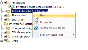
Enter Automatic Cell Planning, to adjust the parameters we set to find the most optimal setup,
We’ll right click on ACP – Automatic Cell Planning and create a new one.
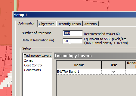
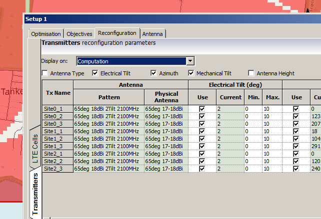
From here we set how many iterations we want to try out (more leads to better results but takes longer to compute), the parameters we want to change (ie Azimuth, Tilt, Antenna type, etc).
Setting number of iterations – Higher leads to better results but takes longer to calculate and has diminishing returnsWe’ll allow the Tilt (Electrical & Mechanical) to be adjusted as well as the Azimuth of each antenna.
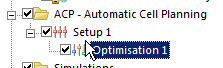
When you’ve set the parameters you want, click Run and Atoll will start running through possible parameter combinations and measuring how they perform.
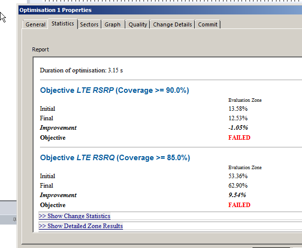
Once it’s run you’ll be able to view the Optomization
The report shows you the results, improvements in RSSI and RSSQ;
Here we can see we boosted the RSRQ (The quality of the signal) by 9.5%, but had to sacrifice RSRP (Signal power) by 1%.
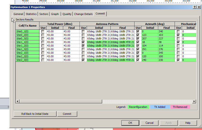
Sacrificies have to be made, and if you’re happy with this you can view the details of the changes, and commit the adjustments.
Committing the changes adjusts all the Transmitters in the area to the listed values, after which we can run our Predictions again to compare like we did earlier.
So that’s what we’ve got when we randomly place sites, we can use Atoll to optomize what we’ve already got, but what if we left the picking of cell sites up to Atoll to look for better options?
In our next post we’ll look at Site Selection using ACP, and constraining it. This means we can tell Atoll to just find the best sites, or load in a list of possible sites and let Atoll determine which are the best candidates.
You’ve done the flatland model we did Part 1 and now you’re pumped up and ready to start plotting your cell sites, optimizing your coverage and boosting the services you’re offering.
But one thing stands in your way – The predicted & modeled data we get out of Atoll is only going to be as good as the data we’ve given it, the old garbage in garbage out adage.
So let’s get started, we’ll create a new document from Template again and select LTE.
Setting our Projection
Now before we go throwing out cell sites we’re going to have to tell Atoll where we are, this can get a little tricky if you’re setting this up for a different real world location, but stick with me and I’ll give you the data you need for this example.
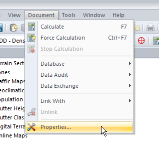
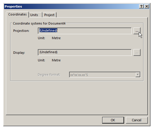
We’ll select Document -> Properties and we’ve got to define a projection,
A projection is essentially a coordinate system, like Latitude and Longitude, that constrains our project to somewhere on this planet.
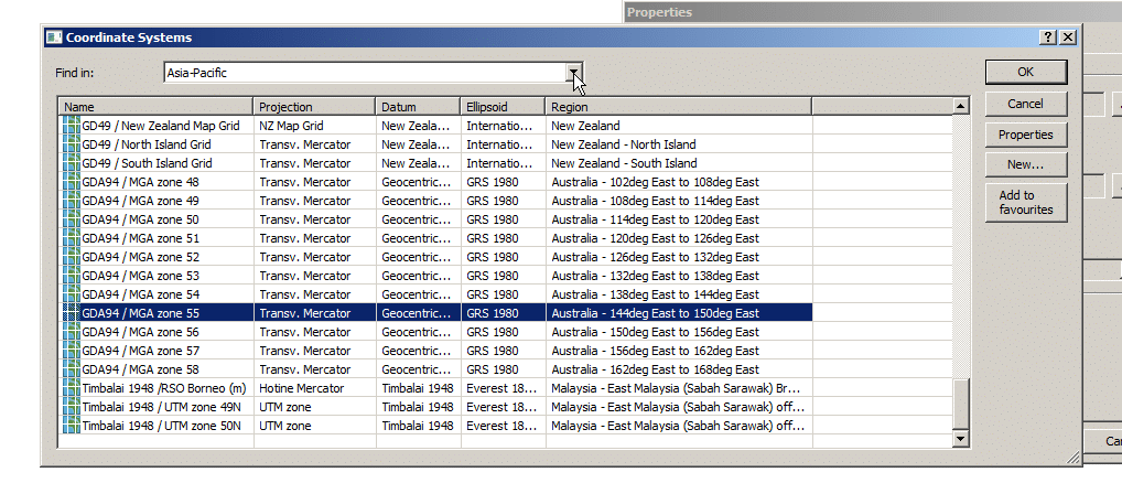
In this example we’re in Australia, so we’ll select Asia Pacific from the “Find In” section and scroll until we find MGA Zone 55. We’ll select it and click OK.
All this Zone information makes sense to GIS folks, there’s lots of information online about UTM datums, projections and GIS, which can help you select the right Coordinate system and projection for your particular area – But for us we’ll select MGA Zone 55 and that’s the last we’ll hear about it.
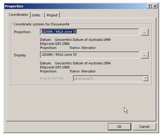
So now we’ve got that information setup we’ll hit Ok again and be on our way. Atoll now knows where in the world we are and we can start filling in the specifics.
So now we’ve still got an empty map with nothing to show, so let’s add some data.
Adding Population and Roads
We’ll start by adding some base data, we’ll import a footprint of the Island and a map of all the roads.
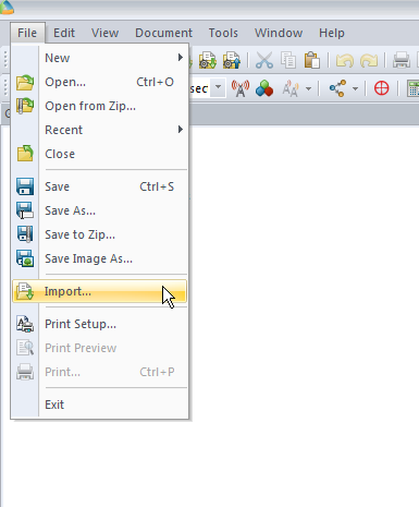
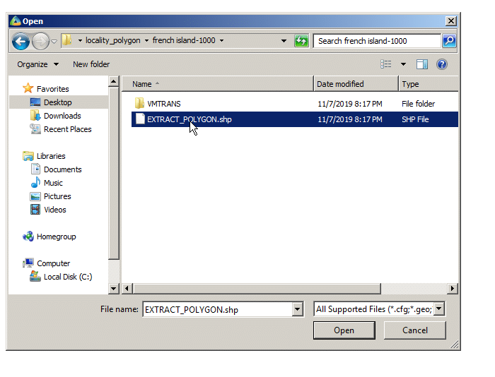
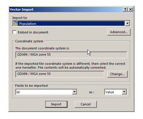
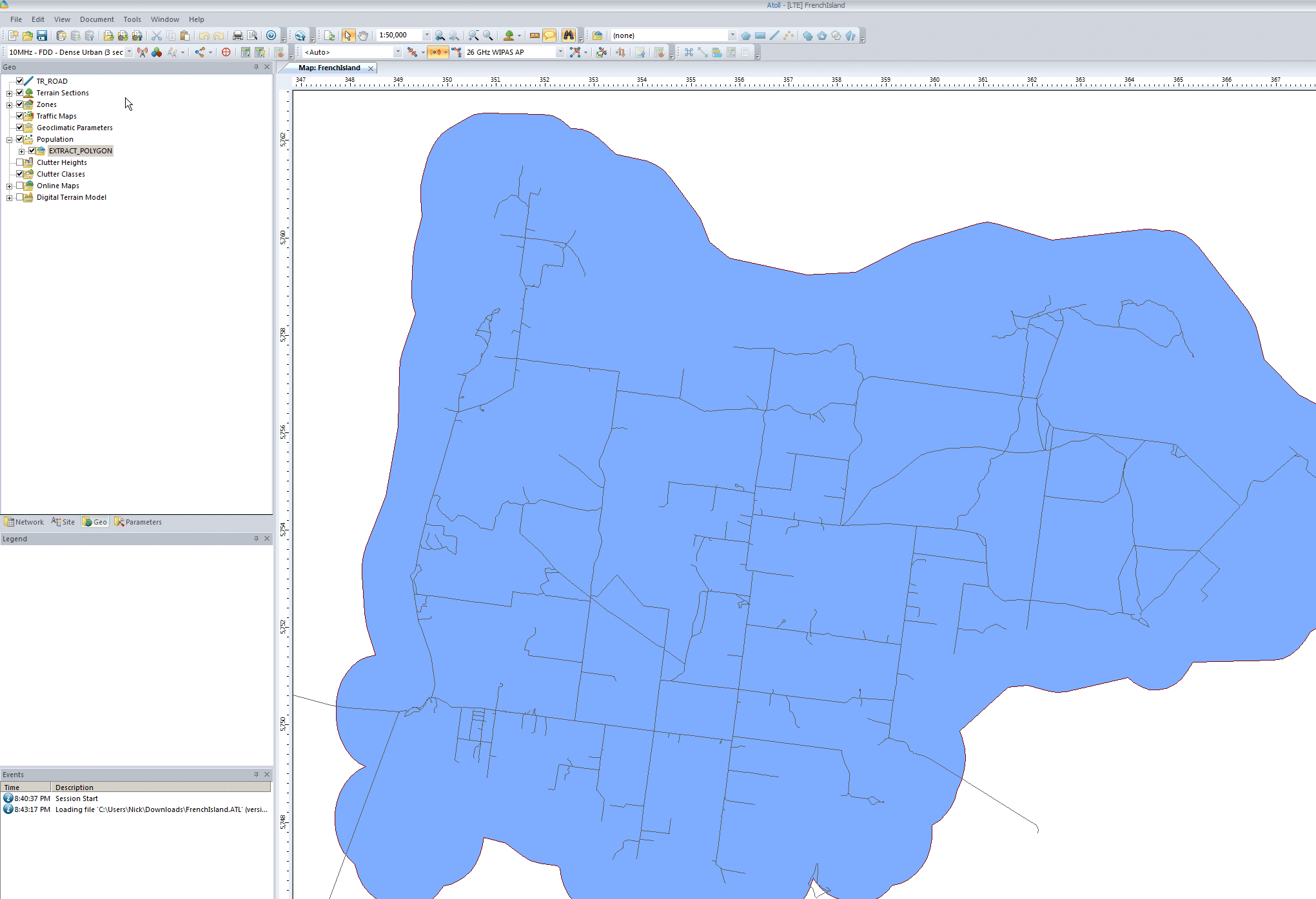
First we’ll import the populated area outline it into Atoll from File -> Import and select the file called EXTRACT_POLYGON.shp
We’ll put it into the population folder, this will be useful later when we try and ensure this area is covered by our network.
Although the population data is kind of rough ( <100 for the entire area) it’s still very useful for limiting our coverage area and saying “We’ve got everyone covered” when it comes to coverage.
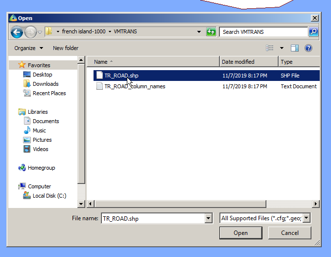
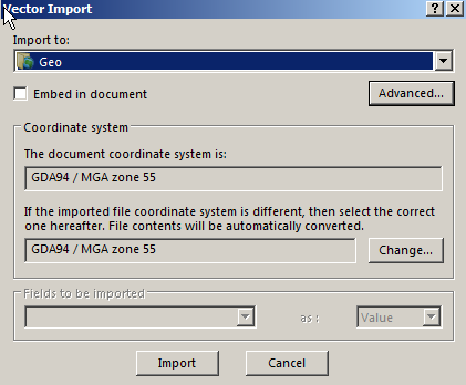
Next up we’ll import the roads file, same thing, File -> Import, TR_ROAD.shp
We’ll import it to the Geo folder – This is just data that Atoll doesn’t process but is useful to us as humans.
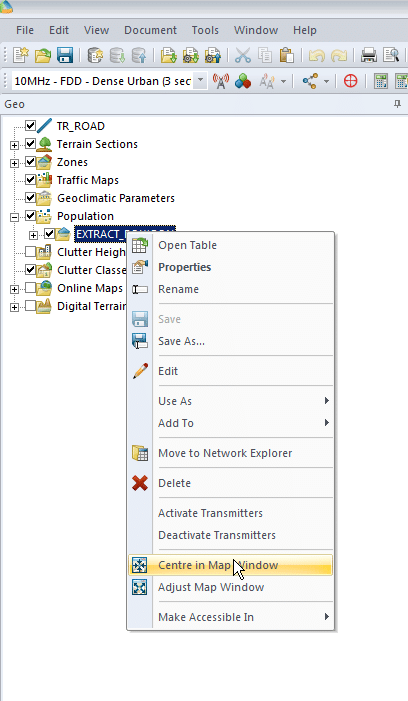
Finally we’ll enable the layers we’ve just imported and center the map on our imported data to get us in the right region. We’ll do this by expanding “Population”, right clicking on the file we just imported and selecting “Center in Map Window”
You may have to tick the layer to enable itPopulation footprint with roads
Adding Elevation Data
Again, like our Datum elevation data is a standard GIS concept, but if you’re from an RF background you’ve probably not come across it, essentially it’s an image where the shade of each pixel translates to a height above sea level.
We import it into Atoll and it’s used in propagation modeling – after all we need to know if there’s a hill / mountain / valley in the way, and even slight rises / dips in the geography can have an impact on your coverage.
We’ll start by downloading the file above, and then importing it into Atoll
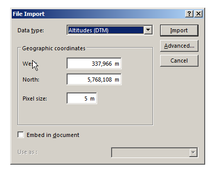
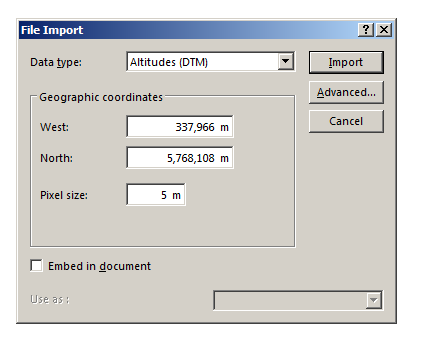
Next we’ll need to tell Atoll the type of data we’re importing (Altitudes) and it’s offset from the 0 point of our coordinate system, I’ve put the information we need for this into a handy table below:
West
337,966
North
5,768,108
Pixel Size
5m
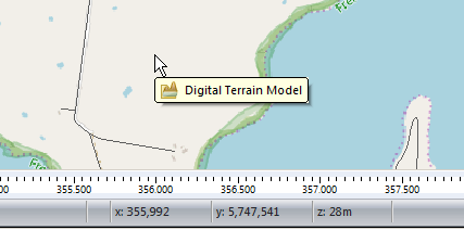
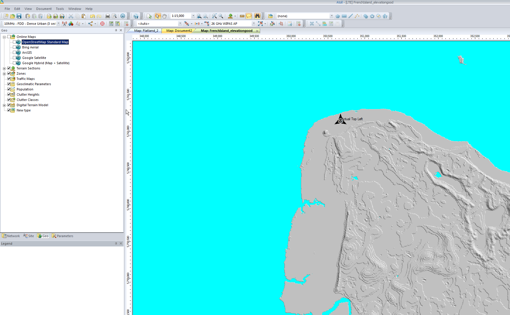
Now when we move our cursor around we’ll see the elevation change in the bottom right ( z is height).
This is because the elevation data is kind of invisible (We’re looking top down) but it’s there.
Adding a Map Overlay
Ok, you’ve made it this far, let’s finally get out of our white blank map and give it some things that make it look like a map!
In order to add Google Maps / Bing Maps etc as an overlay for the first time, we’ve got to restart Atoll, be sure to save your work first.
Done that? Good, let’s add some map tiles.
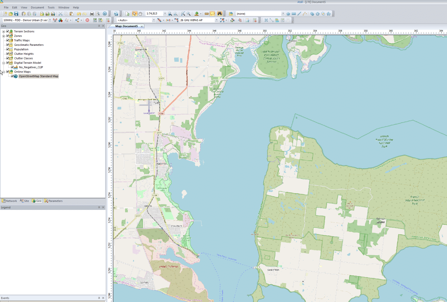
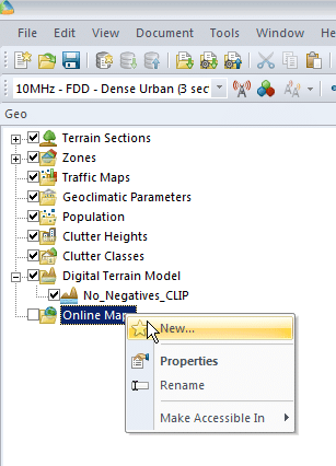
We’ll right click on Online Maps -> New and select a map source from the drop down menu,
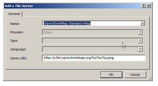
Next we’ll select a tile server, I’m using Open Street Map Standard Map, which I selected from the drop down menu,
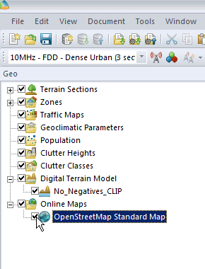
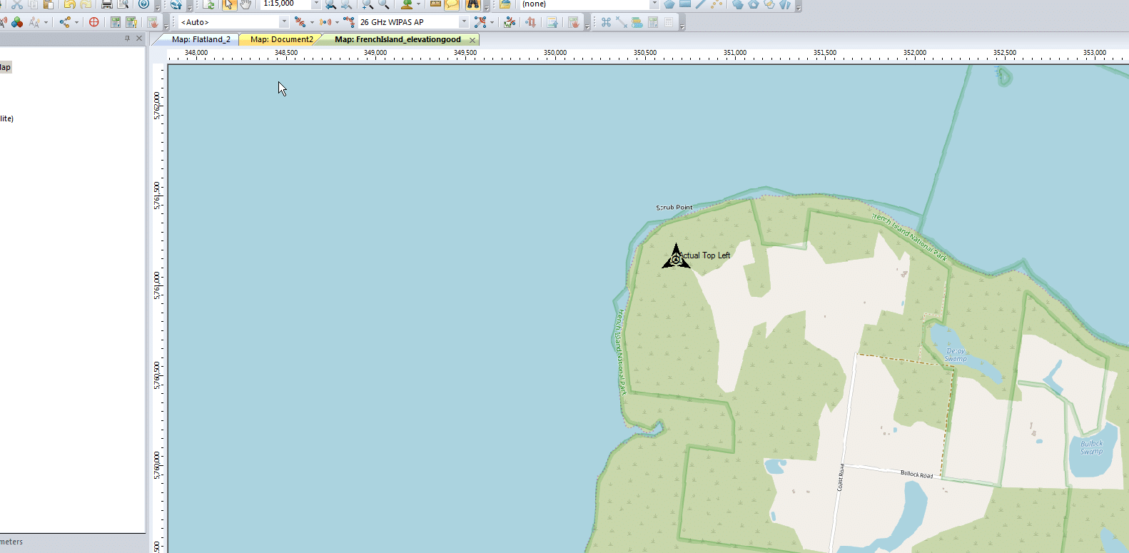
Finally we’ll enable the layer by ticking it on the Geo panel on the right hand side. You may need to drag the layer to the top if you’ve added other layers.
All going well you’ll be looking at a map of the area, and by hovering over an area of land you should see the elevation data too.
We can even add other map layers and toggle between them or set the order by dragging them up and down.
Summary
So now we’ve got Atoll configured for our part of the world, imported height data, population data and roads, and added some map layers so we can see what we’re up to.
An important point to keep in mind is the more accurate the data you feed into Atoll, the more real-world the results you’ll get out of it will be.
Although filling in map layers and adding information seems tedious – and it is – the data-in data-out approach applies here, so the more quality data we put in the better.
If you’re doing this yourself in the real world contact your Government, they often publish large amounts of geospatial data like elevation, population, roads, land boundaries, and it’s often free.
I’ve attached my working file for you to play with in case you had any issues.
I’ve been working for some time on open source mobile network cores, and one feature that has been a real struggle for a lot of people (Myself included) is getting VoLTE / IMS working.
Here’s some of the issues I’ve faced, and the lessons I learned along the way,
Sadly on most UEs / handsets, there’s no “Make VoLTE work now” switch, you’ve got a satisfy a bunch of dependencies in the OS before the baseband will start sending SIP anywhere.
Get the right Hardware
Your eNB must support additional bearers (dedicated bearers I’ve managed to get away without in my testing) so the device can setup an APN for the IMS traffic.
Sadly at the moment this rules our Software Defined eNodeBs, like srsENB.
ISIM – When you thought you understood USIMs – Guess again
According to the 3GPP IMS docs, an ISIM (IMS SIM) is not a requirement for IMS to work.
However in my testing I found Android didn’t have the option to enable VoLTE unless an ISIM was present the first time.
In a weird quirk I found once I’d inserted an ISIM and connected to the VoLTE network, I could put a USIM in the UE and also connect to the VoLTE network.
Obviously the parameters you can set on the USIM, such as Domain, IMPU, IMPI & AD, are kind of “guessed” but the AKAv1-MD5 algorithm does run.
Getting the APN Config Right
There’s a lot of things you’ll need to have correct on your UE before it’ll even start to think about sending SIP messaging.
I was using commercial UE (Samsung handsets) without engineering firmware so I had very limited info on what’s going on “under the hood”. There’s no “Make VoLTE do” tickbox, there’s VoLTE enable, but that won’t do anything by default.
If your P-GW doesn’t know the IP of your P-CSCF, it’s not going to be able to respond to it in the Protocol Configuration Options (PCO) request sent by the UE with that nice new bearer for IMS we just setup.
There’s no way around Mutual Authentication
Coming from a voice background, and pretty much having RFC 3261 tattooed on my brain, when I finally got the SIP REGISTER request sent to the Proxy CSCF I knocked something up in Kamailio to send back a 200 OK, thinking that’d be the end of it.
For any other SIP endpoint this would have been fine, but IMS Clients, nope.
Reading the specs drove home the same lesson anyone attempting to setup their own LTE network quickly learns – Mutual authentication means both the network and the UE need to verify each other, while I (as the network) can say the UE is OK, the UE needs to check I’m on the level.
I saw my 401 response go back to the UE and then no response. Nada.
This led to my next lesson…
There’s no way around IPsec
According to the 3GPP docs, support for IPsec is optional, but I found this not to be the case on the handsets I’ve tested.
After sending back my 401 response the UE looks for the IPsec info in the 401 response, then tries to setup an IPsec SA and sends ESP packets back to the P-CSCF address.
Even with my valid AKAv1-MD5 auth, I found my UE wasn’t responding until I added IPsec support on the P-CSCF, hence why I couldn’t see the second REGISTER with the Authentication Info.
After setting up IPsec support, I finally saw the UE’s REGISTER with the AKAv1-MD5 authentication, and was able to send a 200 OK.
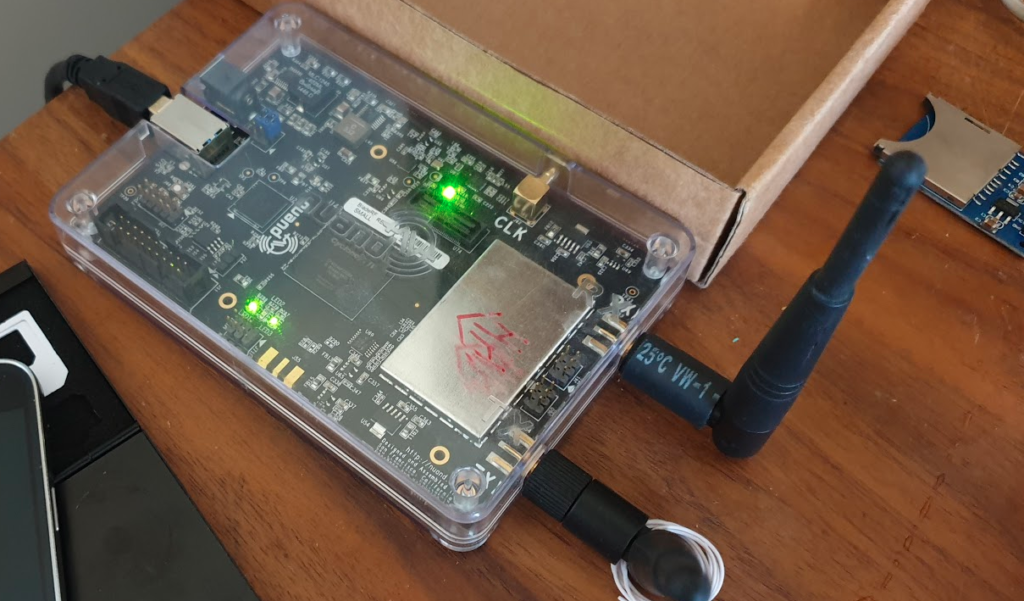
For my LTE lab I got myself a BaiCells Neutrino, it operates on Band 3 (FDD ~1800Mhz) with only 24dBm of output power max and PoE powered it works well in a lab environment without needing -48vDC supply, BBUs, DUs feeders and antennas.
Setup can be done via TR-069 or via BaiCells management server, for smaller setups the web UI makes setup pretty easy,
Logging in with admin/admin to the web interface:
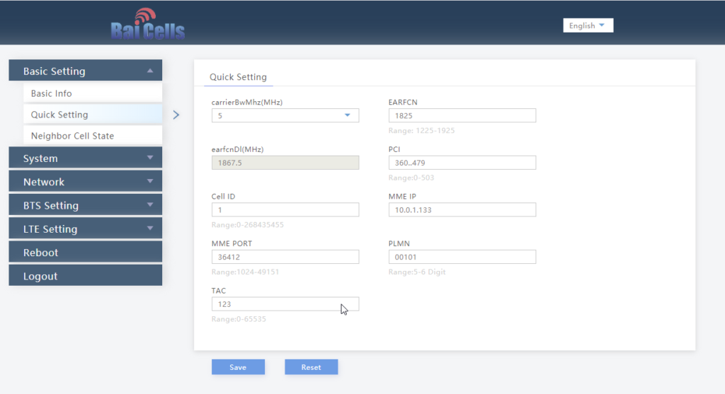
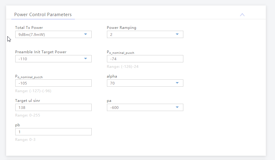
We’ll select Quick Settings, and load in our MME IP address, PLMN (MCC & MNC), Tracking Area Code, Cell ID and Absolute Radio Frequency No.
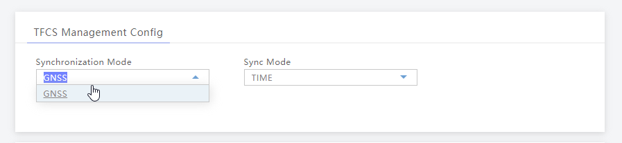
Once that’s done we’ll set our Sync settings to use GPS / GNSS (I’ve attached an external GPS Antenna purchased cheaply online).
Finally we’ll set the power levels, my RF blocking setup is quite small so I don’t want excess power messing around with it, so I’ve dialed the power right back:
And that’s it, it’ll now connect to my MME on 10.0.1.133 port 36412 on SCTP.
The Proxy-Call Session Control Function is the first network element a UE sends it’s SIP REGISTER message to, but how does it get there?
To begin with our UE connects as it would normally, getting a default bearer, an IP address and connectivity.
Overview
If the USIM has an ISIM application on it (or IMS is enabled on the UE using USIM for auth) and an IMS APN exists on the UE for IMS, the UE will set up another bearer in addition to the default bearer.
This bearer will carry our IMS traffic and allow QoS to be managed through the QCI values set on the bearer.
While setting up the bearer the UE requests certain parameters from the network in the Protocol Configuration Options element, including the P-CSCF address.
When setting up the bearer the network responds with this information, which if supported includes the P-CSCF IPv4 &/or IPv6 addresses.
The Message Exchange
We’ll start assuming the default bearer is in place & our UE is configured with the APN for IMS and supports IMS functionality.
The first step is to begin the establishment of an additional bearer for the IMS traffic.
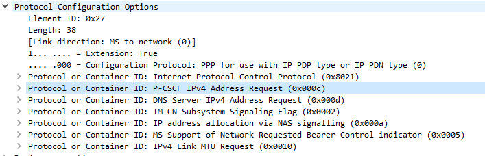
This is kicked off through the Uplink NAS Transport, PDN Connectivity Request from the UE to the network. This includes the IMS APN information, and the UE’s NAS Payload includes the Protocol Configuration Options element (PCO), with a series of fields the UE requires responses from the network. including DNS Server, MTU, etc.
In the PCO the UE also includes the P-CSCF address request, so the network can tell the UE the IP of the P-CSCF to use.
If this is missing it’s because either your APN settings for IMS are not valid, or your device doesn’t have IMS support or isn’t enabling it.(that could be for a few reasons).
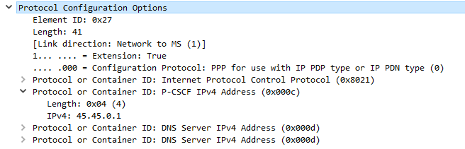
Protocol Configuration Options (Unpopulated) used to request information from the Network by the UE
The MME gets this information from the P-GW, and the network responds in the E-RAB Setup Request, Activate default EPS bearer Context Request and includes the Protocol Configuration Options again, this time the fields are populated with their respective values, including the P-CSCF Address;
Once the UE has this setup, the eNB confirms it’s setup the radio resources through the E-RAB Setup Response.
One the eNB has put the radio side of things in place, the UE confirms the bearer assignment has completed successfully through the Uplink NAS Transport, Activate default EPS Bearer Accept, denoting the bearer is now in place.
Now the UE has the IP address(s) of the P-CSCF and a bearer to send it over, the UE establishes a TCP socket with the address specified in the P-CSCF IPv4 or IPv6 address, to start communicating with the P-CSCF.
The SIP REGISTER request can now be sent and the REGISTRATION procedure can begin.
The team at Software Radio Systems in Ireland have been working on an open source LTE stack for some time, to be used with software defined radio (SDR) hardware like the USRP, BladeRF and LimeSDR.
They’ve released SRSUE and SRSENB their open source EUTRAN UE and eNodeB, which allow your SDR hardware to function as a LTE UE and connect to a commercial eNB like a standard UE while getting all the juicy logs and debug info, or as a LTE eNB and have commercial UEs connect to a network you’re running, all on COTS hardware.
The eNB supports S1AP to connect to a 3GPP compliant EPC, like Open5Gs, but also comes bundled with a barebones EPC for testing.
The UE allows you to do performance testing and gather packet captures on the MAC & PHY layers, something you can’t do on a commericial UE. It also supports software-USIMs (IMSI / K / OP variables stored in a text file) or physical USIMs using a card reader.
I’ve got a draw full of SDR hardware, from the first RTL-SDR dongle I got years ago, to a few HackRFs, a LimeSDR up to the BladeRF x40.
Really cool software to have a play with, I’ve been using SRSUE to get a better understanding of the lower layers of the Uu interface.
Installation
After mucking around trying to satisfy all the dependencies from source I found everything I needed could be found in Debian packages from the repos of the maintainers.
To begin with we need to install the BladeRF drivers and SopySDR modules to abstract it to UHD:
For most Voice / Telco engineers IPsec is a VPN technology, maybe something used when backhauling over an untrusted link, etc, but voice over IP traffic is typically secured with TLS and SRTP.
IMS / Voice over LTE handles things a bit differently, it encapsulates the SIP & RTP traffic between the UE and the P-CSCF in IPsec Encapsulating Security Payload (ESP) payloads.
In this post we’ll take a look at how it works and what it looks like.
It’s worth noting that Kamailio recently added support for IPsec encapsulation on a P-CSCF, in the IMS IPSec-Register module. I’ll cover usage of this at a later date.
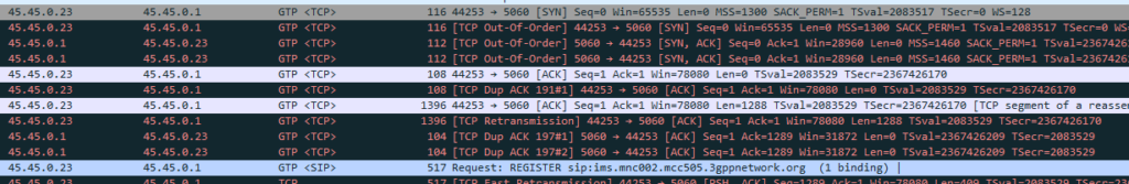
The Message Exchange
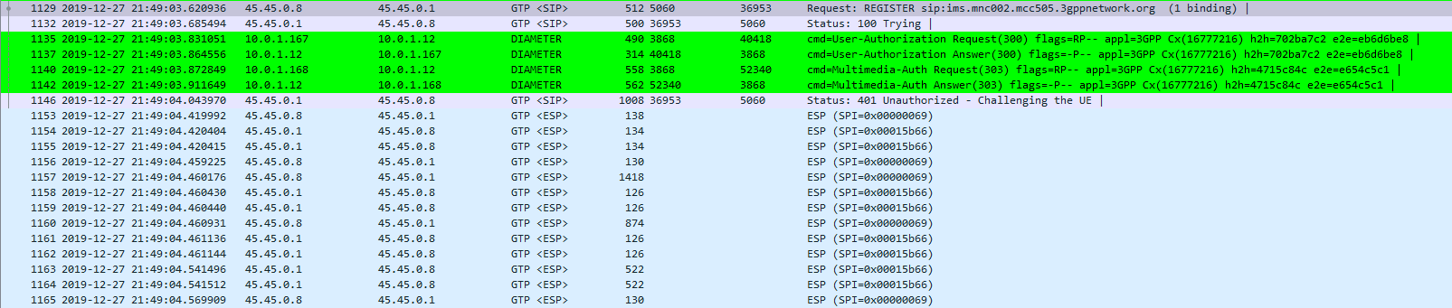
The exchange starts off looking like any other SIP Registration session, in this case using TCP for transport. The UE sends a REGISTER to the Proxy-CSCF which eventually forwards the request through to a Serving-CSCF.
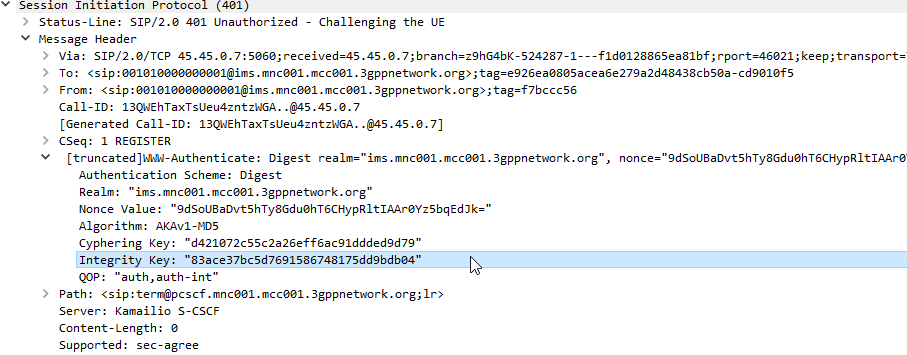
This is where we diverge from the standard SIP REGISTER message exchange. The Serving-CSCF generates a 401 Unauthorized response, containing an authentication challenge in the WWW-Authenticate header, and also a Ciphering Key & Integrity Key (ck= and ik=) also in the WWW-Authenticate header.
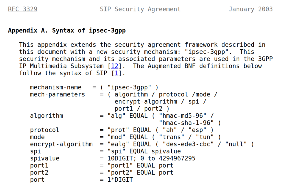
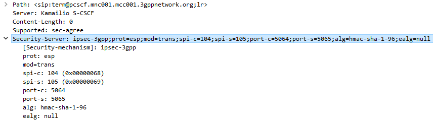
The Serving-CSCF sends the Proxy-CSCF the 401 response it created. The Proxy-CSCF assigns a SPI for the IPsec ESP to use, a server port and client port and indicates the used encryption algorithm (ealg) and algorithm to use (In this case HMAC-SHA-1-96.) and adds a new header to the 401 Unauthorized called Security–Server header to share this information with the UE.
The Proxy-CSCF also strips the Ciphering Key (ck=) and Integrity Key (ik=) headers from the SIP authentication challenge (WWW-Auth) and uses them as the ciphering and integrity keys for the IPsec connection.
Finally after setting up the IPsec server side of things, it forwards the 401 Unauthorized response onto the UE.
Upon receipt of the 401 response, the UE looks at the authentication challenge.
If the network is considered authenticated by the UE it generates a response to the Authentication Challenge, but it doesn’t deliver it over TCP. Using the information generated in the authentication challenge the UE encapsulates everything from the network layer (IPv4) up and sends it to the P-CSCF in an IPsec ESP.
Communication between the UE and the P-CSCF is now encapsulated in IPsec.
Wireshark trace of IPsec IMS Traffic between UE and P-CSCF
IPsec ESP can be used in 3 different ways on the Gm interface between the Ue and the P-CSCF:
Integrity Protection – To prevent tampering
Ciphering – To prevent inception / eavesdropping
Integrity Protection & Ciphering
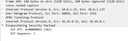
On Wireshark, you’ll see the ESP, but you won’t see the payload contents, just the fact it’s an Encapsulated Security Payload, it’s SPI and Sequence number.
By default, Kamailio’s P-CSCF only acts in Integrity Protection mode, meaning the ESP payloads aren’t actually encrypted, with a few clicks we can get Wireshark to decode this data;
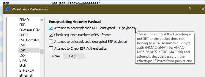
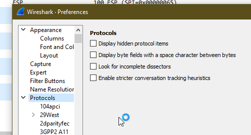
Just open up Wireshark Preferences, expand Protocols and jump to ESP
Now we can set the decoding preferences for our ESP payloads,
In our case we’ll tick the “Attempt to detect/decode NULL encrypted ESP payloads” box and close the box by clicking OK button.
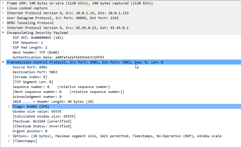
Now Wireshark will scan through all the frames again, anything that’s an ESP payload it will attempt to parse.
Now if we go back to the ESP payload with SQN 1 I showed a screenshot of earlier, we can see the contents are a TCP SYN.
Now we can see what’s going on inside this ESP data between the P-CSCF and the UE!
As a matter of interest if you can see the IK and CK values in the 401 response before they’re stripped you can decode encrypted ESP payloads from Wireshark, from the same Protocol -> ESP section you can load the Ciphering and Integrity keys used in that session to decrypt them.
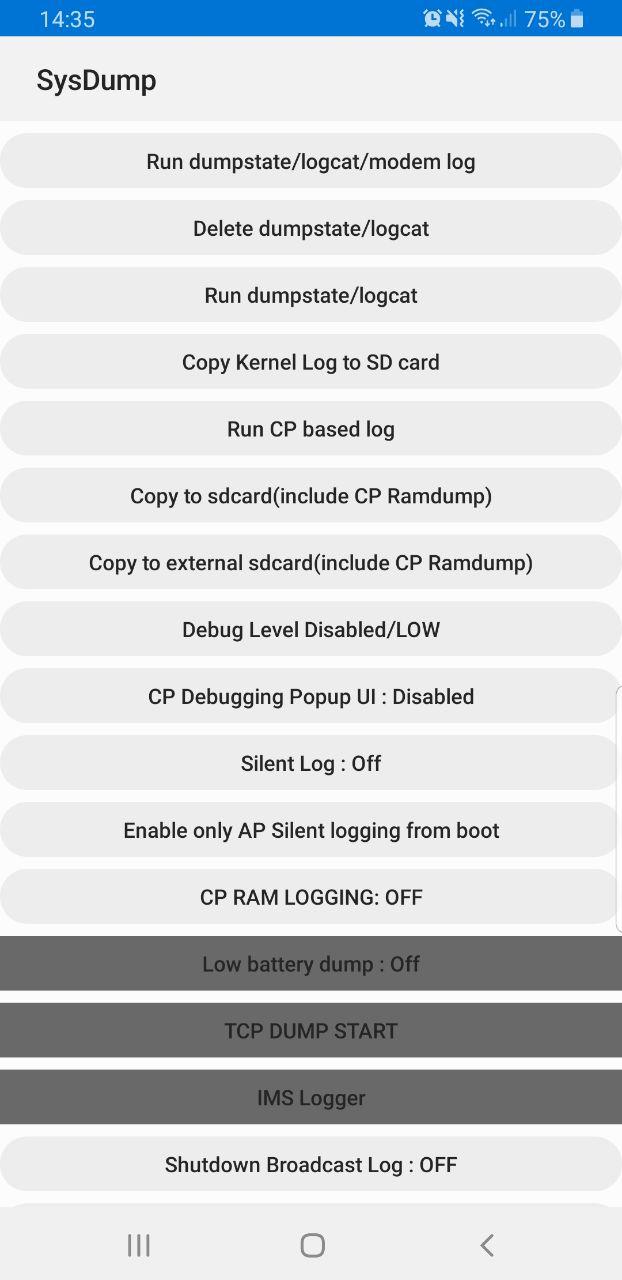
Samsung handsets have a feature built in to allow debugging from the handset, called Sysdump.
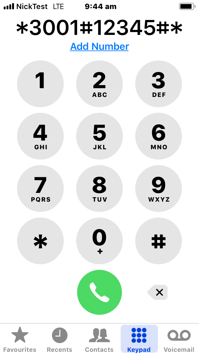
Entering *#9900# from the Dialing Screen will bring up the Sysdump App, from here you can dump logs from the device, and run a variety of debugging procedures.
But for private LTE operators, the two most interesting options are by far the TCPDUMP START option and IMS Logger, but both are grayed out.
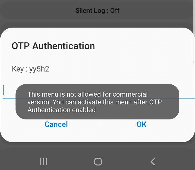
Tapping on them asks for a one-time password and has a challenge key.
These options are not available in the commercial version of the OS and need to be unlocked with a one time key generated by a tool Samsung for unlocking engineering firmware on handsets.
Luckily this authentication happens client side, which means we can work out the password it’s expecting.
Once you’ve entered the code and successfully unlocked the IMS Debugging tool there’s a few really cool features in the hamburger menu in the top right.
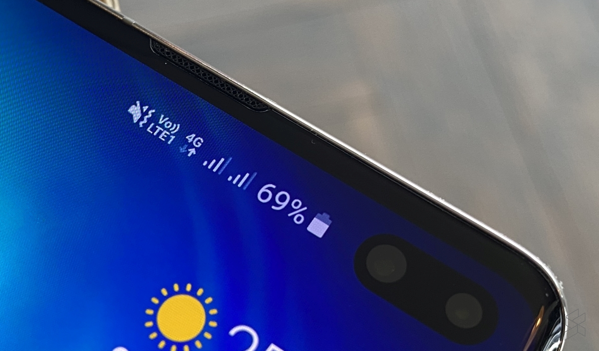
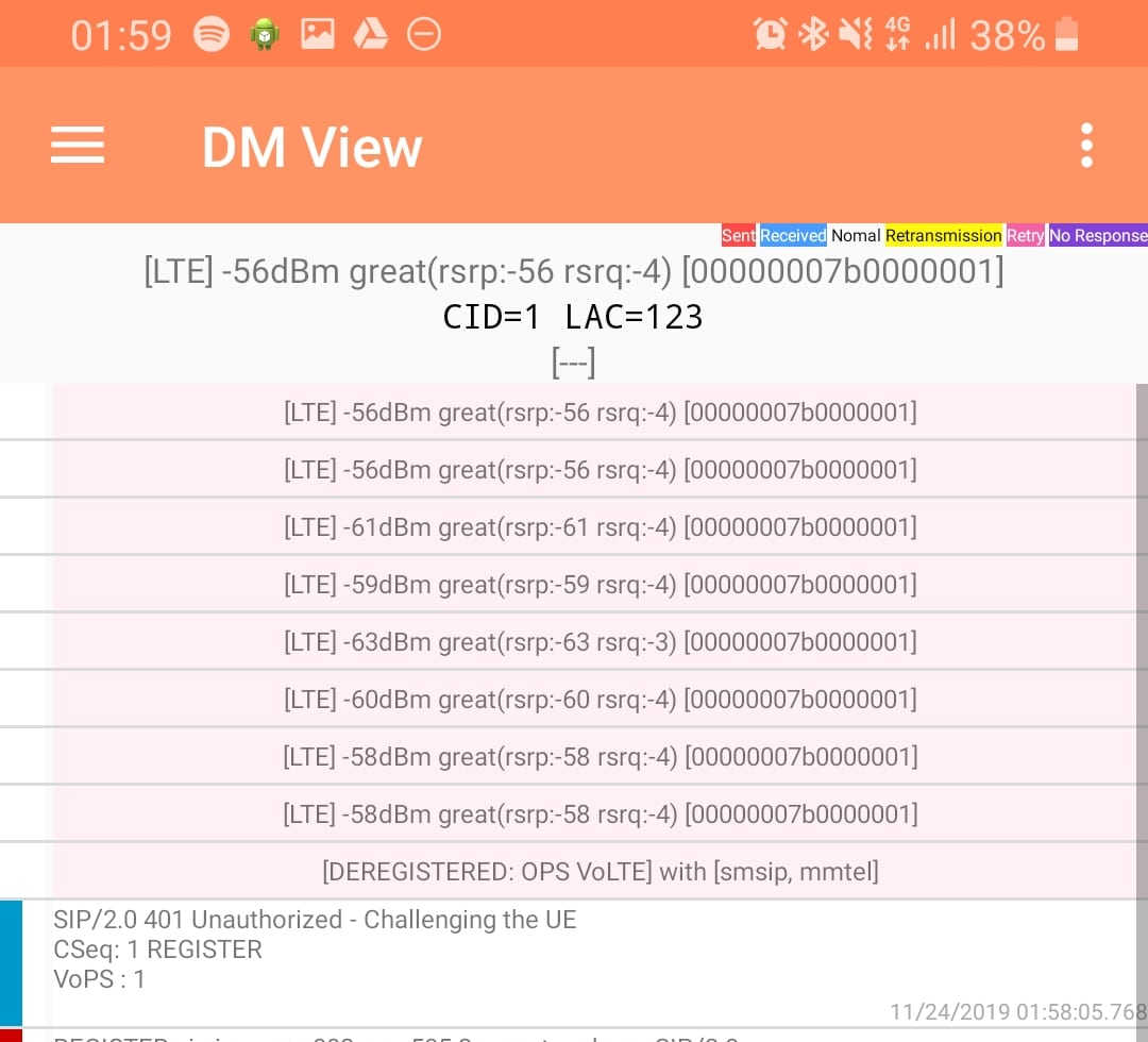
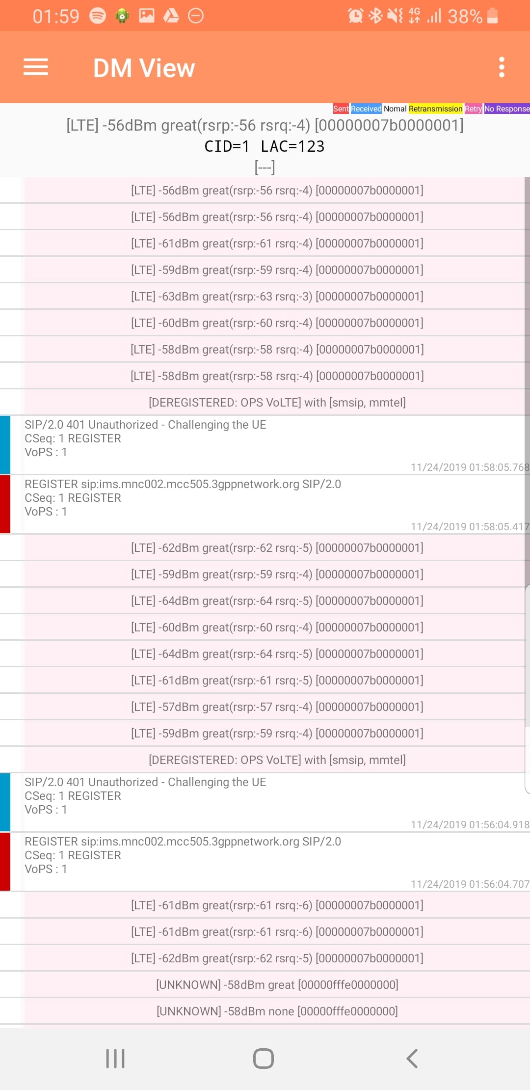
DM View
This shows the SIP / IMS Messaging and the current signal strength parameters (used to determine which RAN type to use (Ie falling back from VoLTE to UMTS / Circuit Switched when the LTE signal strength drops).
Tapping on the SIP messages expands them and allows you to see the contents of the SIP messages.
Viewing SIP Messaging directly from the handset
Interesting the actual nitty-gritty parameters in the SIP headers are missing, replaced with X for anything “private” or identifiable.
Luckily all this info can be found in the Pcap.
The DM View is great for getting a quick look at what’s going on, on the mobile device itself, without needing a PC.
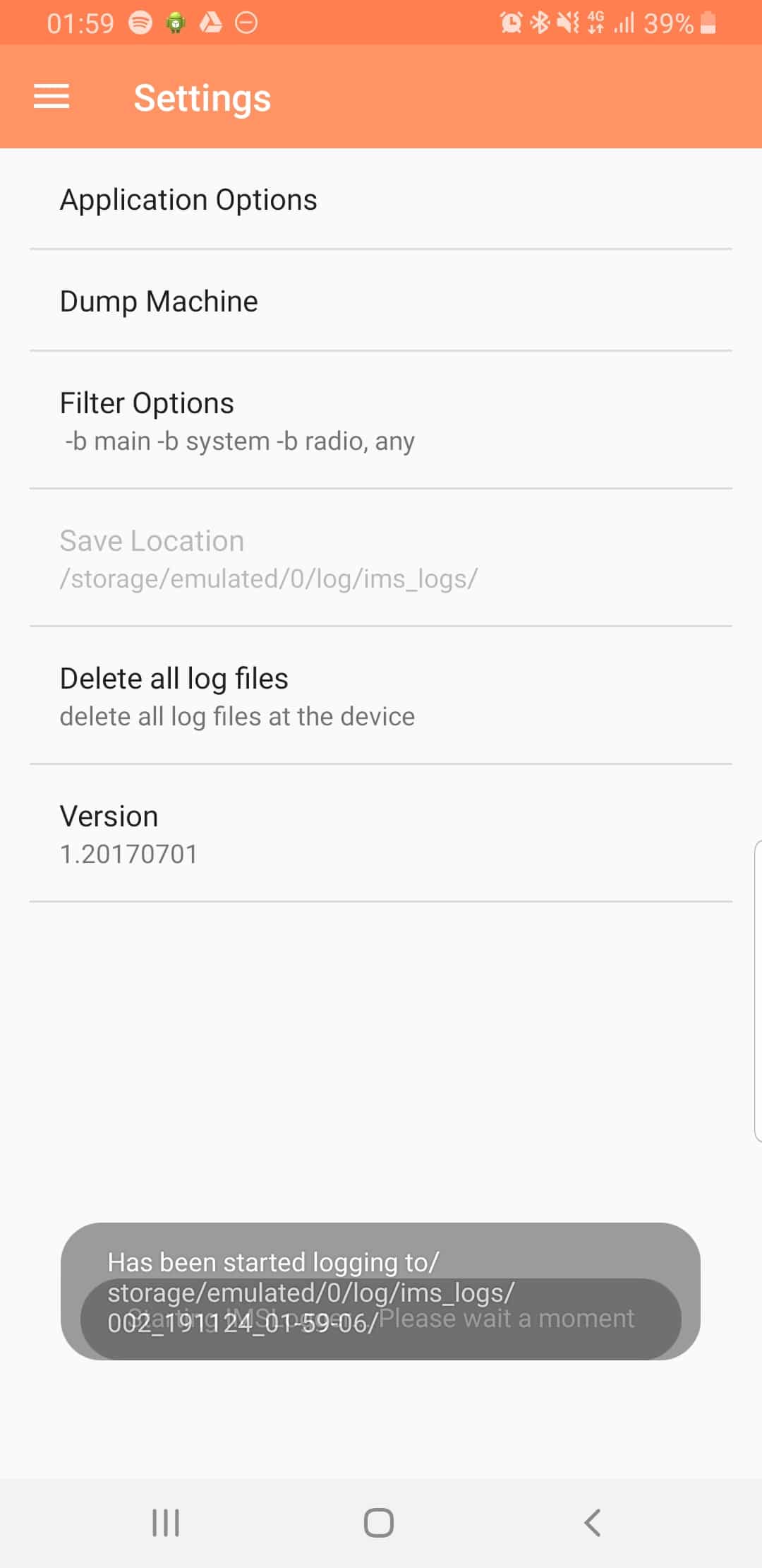
Logging
The real power comes in the logging functions,
There’s a lot of logging options, including screen recording, TCPdump (as in Packet Captures) and Syslog logging.
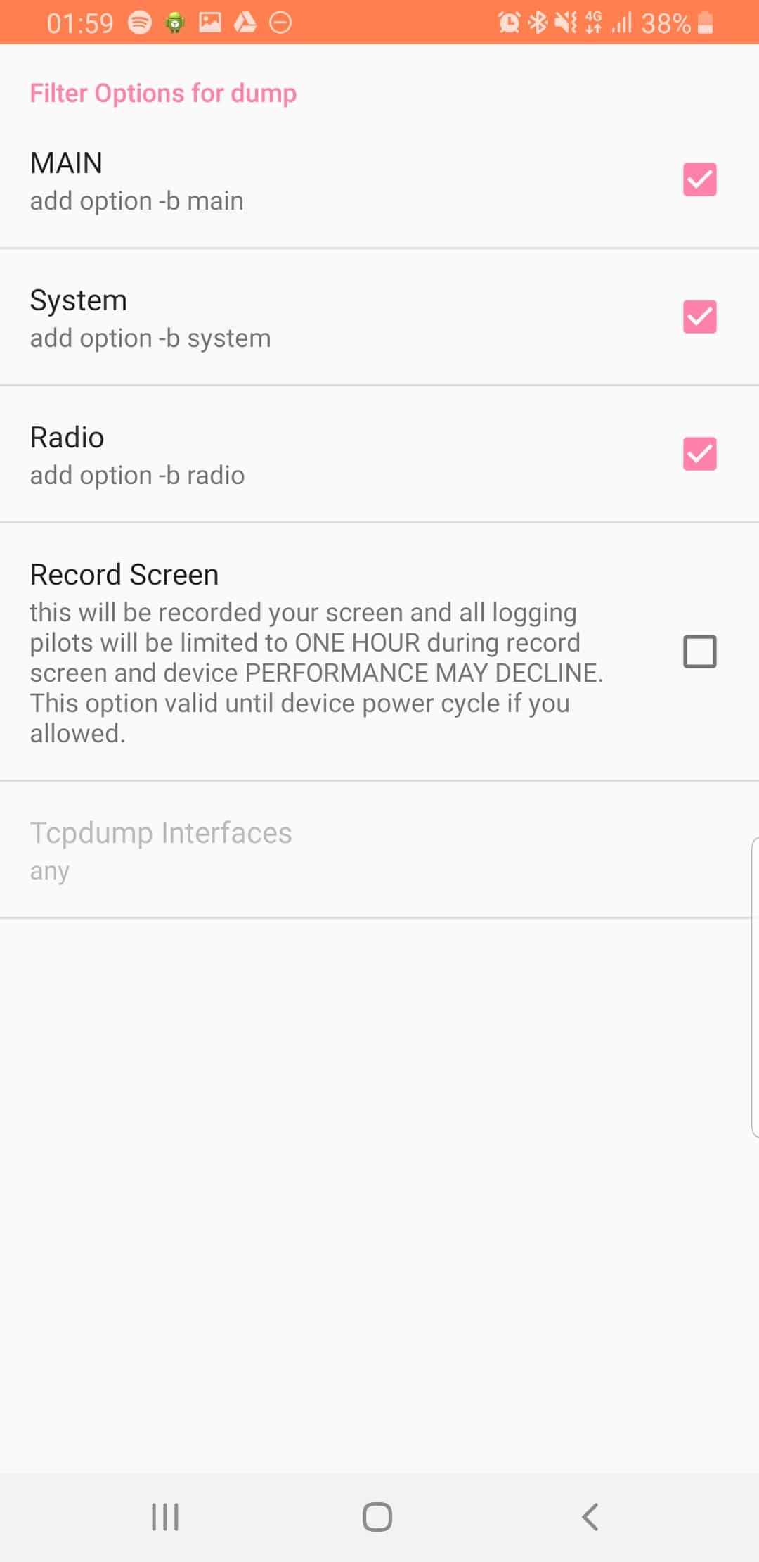
From the hamburger menu we can select the logging parameters we want to change.
From the Filter Options menu we can set what info we’re going to log,
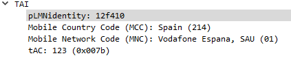
The PLMN Identifier is used to identify the radio networks in use, it’s made up of the MCC – Mobile Country Code and MNC – Mobile Network Code.
But sadly it’s not as simple as just concatenating MCC and MNC like in the IMSI, there’s a bit more to it.
In the example above the Tracking Area Identity includes the PLMN Identity, and Wireshark has been kind enough to split it out into MCC and MNC, but how does it get that from the value 12f410?
This one took me longer to work out than I’d like to admit, and saw me looking through the GSM spec, but here goes:
PLMN Contents: Mobile Country Code (MCC) followed by the Mobile Network Code (MNC). Coding: according to TS GSM 04.08 [14].
If storage for fewer than the maximum possible number n is required, the excess bytes shall be set to ‘FF’. For instance, using 246 for the MCC and 81 for the MNC and if this is the first and only PLMN, the contents reads as follows: Bytes 1-3: ’42’ ‘F6′ ’18’ Bytes 4-6: ‘FF’ ‘FF’ ‘FF’ etc.
TS GSM 04.08 [14].
Making sense to you now? Me neither.
Here’s the Python code I wrote to encode MCC and MNCs to PLMN Identifiers and to decode PLMN into MCC and MNC, and then we’ll talk about what’s happening:
In the above example I take MCC 505 (Australia) and MCC 93 and generate the PLMN ID 05f539.
The first step in decoding is to take the first two bits (in our case 05 and reverse them – 50, then we take the third and fourth bits (f5) and reverse them too, and strip the letter f, now we have just 5. We join that with what we had earlier and there’s our MCC – 505.
Next we get our MNC, for this we take bytes 5 & 6 (39) and reverse them, and there’s our MNC – 93.
Together we’ve got MCC 505 and MNC 93.
The one answer I’m still looking for; why not just encode 50593? What is gained by encoding it as 05f539?
After a few quiet months I’m excited to say I’ve pushed through some improvements recently to PyHSS and it’s growing into a more usable HSS platform.
MongoDB Backend
This has a few obvious advantages – More salable, etc, but also opens up the ability to customize more of the subscriber parameters, like GBR bearers, etc, that simple flat text files just wouldn’t support, as well as the obvious issues with threading and writing to and from text files at scale.
Knock knock.
Race condition.
Who’s there?
— Threading Joke.
For now I’m using the Open5GS MongoDB schema, so the Open5Gs web UI can be used for administering the system and adding subscribers.
The CSV / text file backend is still there and still works, the MongoDB backend is only used if you enable it in the YAML file.
The documentation for setting this up is in the readme.
SQN Resync
If you’re working across multiple different HSS’ or perhaps messing with some crypto stuff on your USIM, there’s a chance you’ll get the SQN (The Sequence Number) on the USIM out of sync with what’s on the HSS.
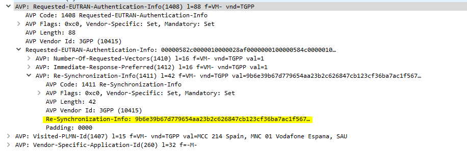
This manifests itself as an Update Location Request being sent from the UE in response to an Authentication Information Answer and coming back with a Re-Syncronization-Info AVP in the Authentication Info AVP. I’ll talk more about how this works in another post, but in short PyHSS now looks at this value and uses it combined with the original RAND value sent in the Authentication Information Answer, to find the correct SQN value and update whichever database backend you’re using accordingly, and then send another Authentication Information Answer with authentication vectors with the correct SQN.
SQN Resync is something that’s really cryptographically difficult to implement / confusing, hence this taking so long.
What’s next? – IMS / Multimedia Auth
The next feature that’s coming soon is the Multimedia Authentication Request / Answer to allow CSCFs to query for IMS Registration and manage the Cx and Dx interfaces.
Code for this is already in place but failing some tests, not sure if that’s to do with the MAA response or something on my CSCFs,
LTE has great concepts like NAS that abstract the actual transport layers, so the NAS packet is generated by the UE and then read by the MME.
One thing that’s a real headache about private LTE is the authentication side of things. You’ll probably bash your head against a SIM programmer for some time.
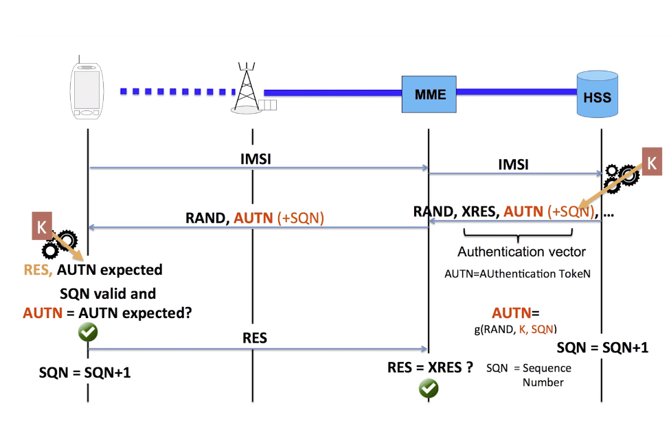
As your probably know when connecting to a network, the UE shares it’s IMSI / TIMSI with the network, and the MME requests authentication information from the HSS using the Authentication Information Request over Diameter.
The HSS then returns a random value (RAND), expected result (XRES), authentication token (AUTN) and a KASME for generating further keys,
The RAND and AUTN values are sent to the UE, the USIM in the UE calculates the RES (result) and sends it back to the MME. If the RES value received by the MME is equal to the expected RES (XRES) then the subscriber is mutually authenticated.
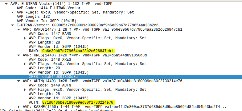
Using this tool I was able to plug a USIM into my USIM reader, using the Diameter client built into PyHSS I was able to ask for Authentication vectors for a UE using the Authentication Information Request to the HSS and was sent back the Authentication Information Answer containing the RAND and AUTN values, as well as the XRES value.
Diameter – Authentication Information Response showing E-UTRAN Vectors
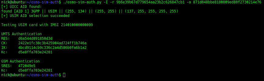
Then I used the osmo-sim-auth app to query the RES and RAND values against the USIM.
The RES I got back matched the XRES, meaning the HSS and the USIM are in sync (SQNs match) and they mutually authenticated.
I thought I’d expand a little on how the Crypto side of things works in LTE & NR (also known as 4G & 5G).
Authentication primarily happens in two places, one at each end of the network, the Home Subscriber Server and in the USIM card. Let’s take a look at each of them.
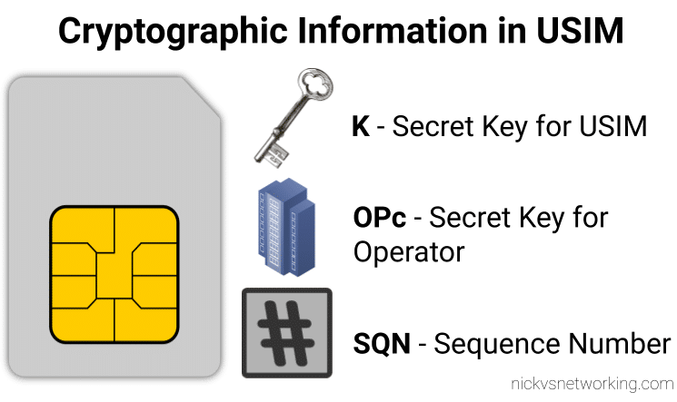
On the USIM
On the USIM we’ve got two values that are entered in when the USIM is provisioned, the K key – Our secret key, and an OPc key (operator key).
These two keys are the basis of all the cryptography that goes on, so should never be divulged.
The only other place to have these two keys in the HSS, which associates each K key and OPc key combination with an IMSI.
The USIM also stores the SQN a sequence number, this is used to prevent replay attacks and is incremented after each authentication challenge, starting at 1 for the first authentication challenge and counting up from there.
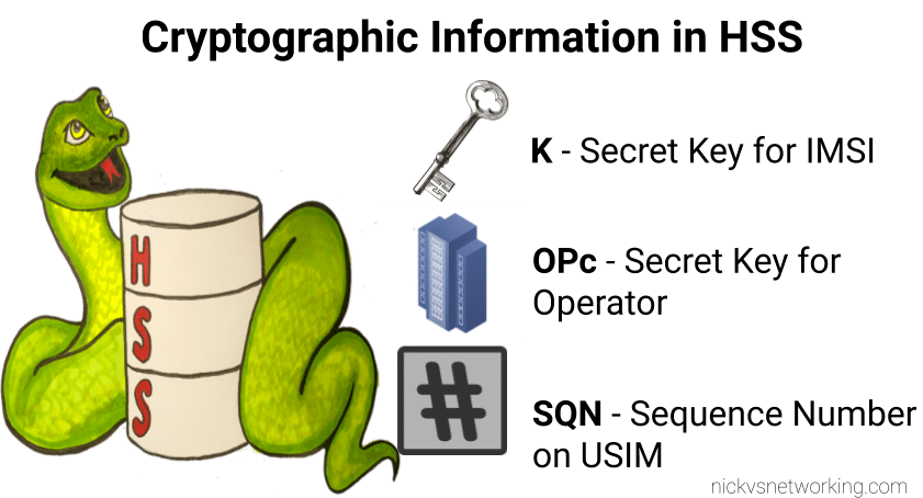
On the HSS
On the HSS we have the K key (Secret key), OPc key (Operator key) and SQN (Sequence Number) for each IMSI on our network.
Each time a IMSI authenticates itself we increment the SQN, so the value of the SQN on the HSS and on the USIM should (almost) always match.
Authentication Options
Let’s imagine we’re designing the authentication between the USIM and the Network; let’s look at some options for how we can authenticate everyone and why we use the process we use.
Failed Option 1 – Passwords in the Clear
The HSS could ask the USIM to send it’s K and OPc values, compare them to what the HSS has in place and then either accept or reject the USIM depending on if they match.
The obvious problem with this that to send this information we broadcast our supposedly secret K and OPc keys over the air, so anyone listening would get our secret values, and they’re not so secret anymore.
This is why we don’t use this method.
Failed Option 2 – Basic Crypto
So we’ve seen that sending our keys publicly, is out of the question.
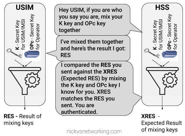
The HSS could ask the USIM to mix it’s K key and OPc key in such a way that only someone with both keys could unmix them.
This is done with some cryptographic black magic, all you need to know is it’s a one way function you enter in values and you get the same result every time with the same input, but you can’t work out the input from the result.
The HSS could then get the USIM to send back the result of mixing up both keys, mix the two keys it knows and compare them.
The HSS mixes the two keys itself, and get’s it’s own result called XRES (Expected Result). If the RES (result) of mixing up the keys by the USIM is matches the result when the HSS mixes the keys in the same way (XRES (Expected Result)), the user is authenticated.
The result of mixing the keys by the USIM is called RES (Result), while the result of the HSS mixing the keys is called XRES (Expected Result).
This is abetter solution but has some limitations, because our special mixing of keys gets the same RES each time we put in our OPc and K keys each time a subscriber authenticates to the network the RES (result) of mixing the keys is going to be the same.
This is vulnerable to replay attacks. An attacker don’t need to know the two secret keys (K & OPc) that went into creating the RES (resulting output) , the attacker would just need to know the result of RES, which is sent over the air for anyone to hear. If the attacker sends the same RES they could still authenticate.
This is why we don’t use this method.
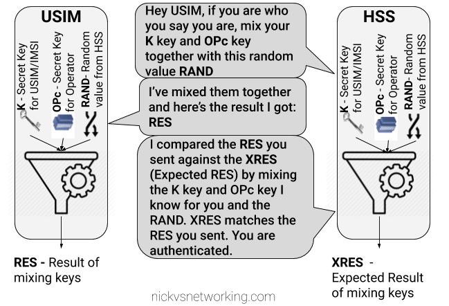
Failed Option 3 – Mix keys & add Random
To prevent these replay attacks we add an element of randomness, so the HSS generates a random string of garbage called RAND, and sends it to the USIM.
The USIM then mixes RAND (the random string) the K key and OPc key and sends back the RES (Result).
Because we introduced a RAND value, every time the RAND is different the RES is different. This prevents against the replay attacks we were vulnerable to in our last example.
If the result the USIM calculated with the K key, OPc key and random data is the same as the USIM calculated with the same K key, OPc key and same random data, the user is authenticated.
While an attacker could reply with the same RES, the random data (RAND) will change each time the user authenticates, meaning that response will be invalid.
While an attacker could reply with the same RES, the random data (RAND) will change each time the user authenticates, meaning that response will be invalid.
The problem here is now the network has authenticated the USIM, the USIM hasn’t actually verified it’s talking to the real network.
This is why we don’t use this method.
GSM authentication worked like this, but in a GSM network you could setup your HLR (The GSM version of a HSS) to allow in every subscriber regardless of what the value of RES they sent back was, meaning it didn’t look at the keys at all, this meant attackers could setup fake base stations to capture users.
Option 4 – Mutual Authentication (Real World*)
So from the previous options we’ve learned:
Our network needs to authenticate our subscribers, in a way that can’t be spoofed / replayed so we know who to bill & where to route traffic.
Our subscribers need to authenticate the network so they know they can trust it to carry their traffic.
So our USIM needs to authenticate the network, in the same way the network authenticates the USIM.
To do this we introduce a new key for network authentication, called AUTN.
The AUTN key is generated by the HSS by mixing the secret keys and RAND values together, but in a different way to how we mix the keys to get RES. (Otherwise we’d get the same key).
This AUTN key is sent to the USIM along with the RAND value. The USIM runs the same mixing on it’s private keys and RAND the HSS did to generate the AUTN , except this is the USIM generated – An Expected AUTN key (XAUTN). The USIM compares XAUTN and AUTN to make sure they match. If they do, the USIM then knows the network knows their secret keys.
The USIM then does the same mixing it did in the previous option to generate the RES key and send it back.
The network has now authenticated the subscriber (HSS has authenticated the USIM via RES key) and the subscriber has authenticated the USIM (USIM authenticates HSS via AUTN key).
*This is a slightly simplified version of how EUTRAN / LTE authentication works between the HSS and the USIM – In reality there are a few extra values, such as SQN to take into consideration and the USIM talks to to the MME not the HSS directly.
I’ll do a follow up post covering the more nitty-gritty elements, AMF and SQN fields, OP vs OPc keys, SQN Resync, how this information is transfered in the Authentication Information Answer and how KASME keys are used / distributed.
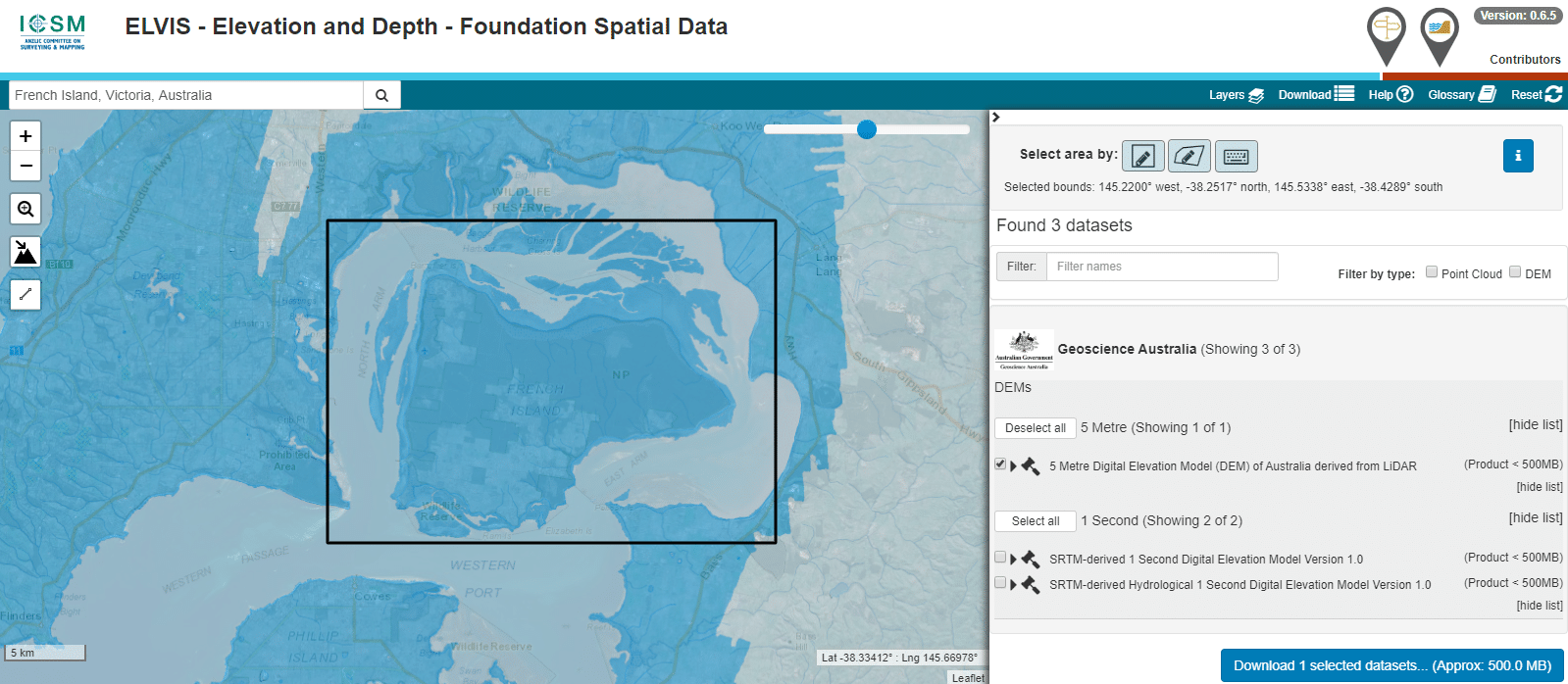
The Australian Government publishes elevation data online that’s freely available for anyone to use. There’s a catch – If you’re using Forsk Atoll, it won’t import without a fair bit of monkeying around with the data…
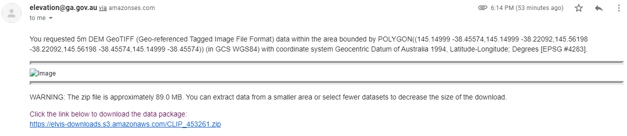
You draw around the area you want to download, enter your email address and you’re linked to a download of the dataset you’ve selected.
So now we download the data from the link, unzip it and we’re provided with a .tiff image with the elevation data in the pixel colour and geocoded with the positional information.
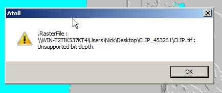
Problem is, this won’t import into Atoll – Unsupported depth.
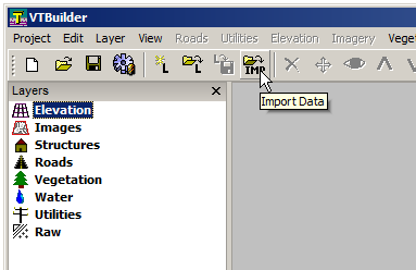
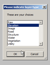
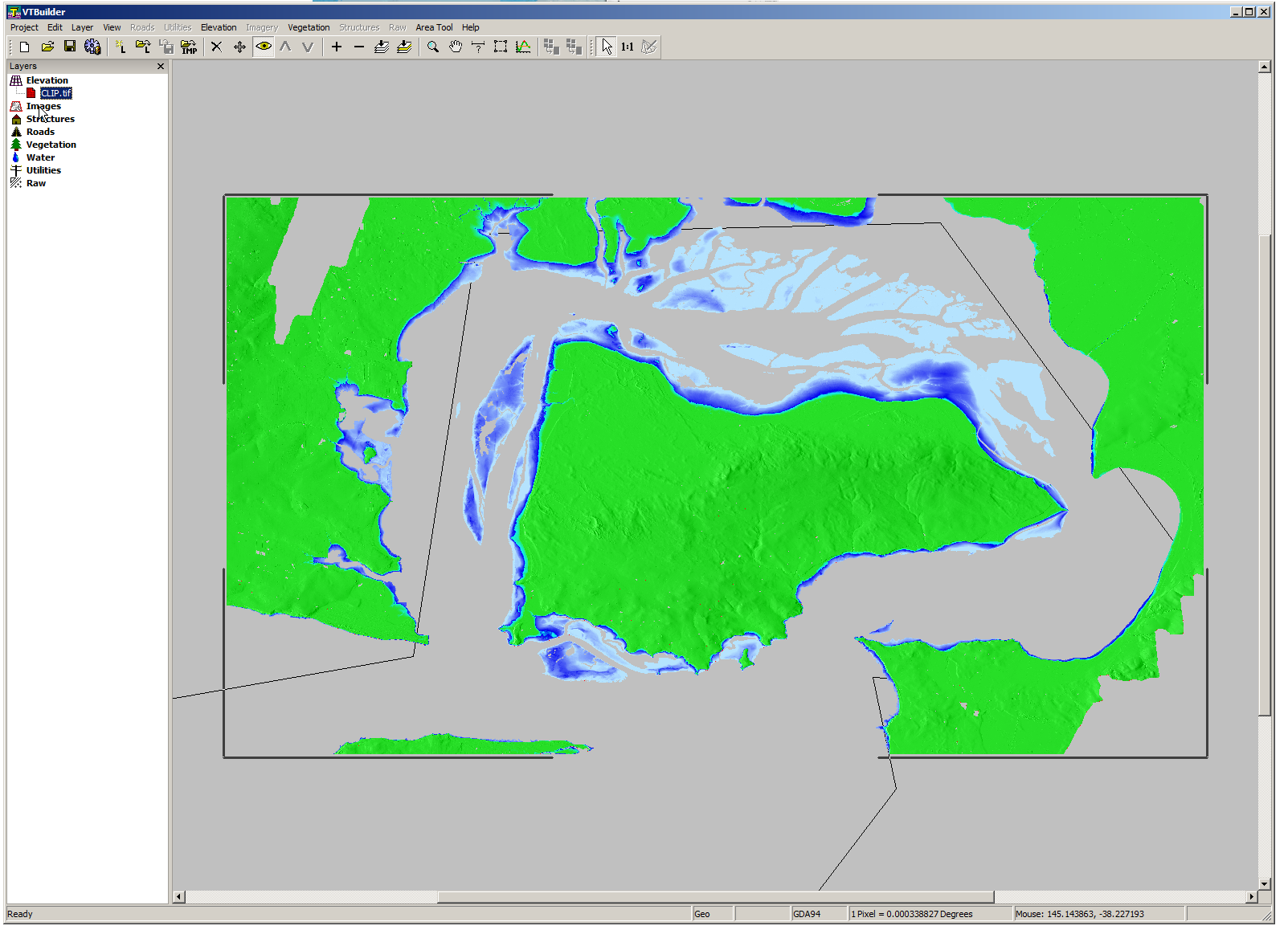
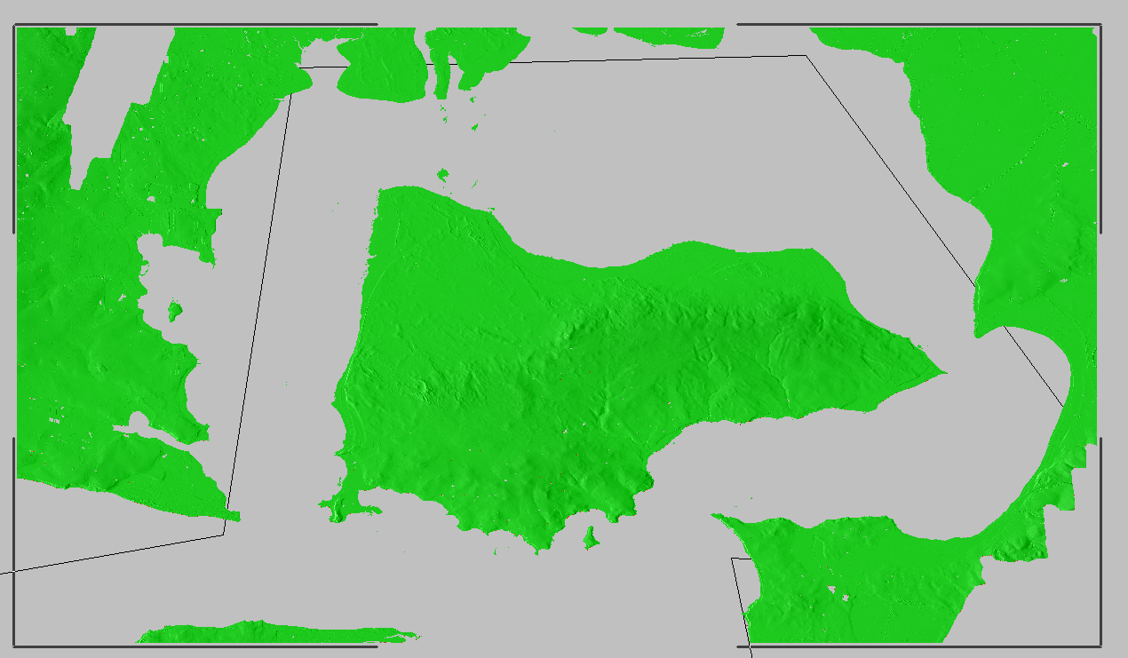
I fired it up, and imported the elevation tiff file we’d downloaded.
Selected “Elevation” waited a few seconds and presto!
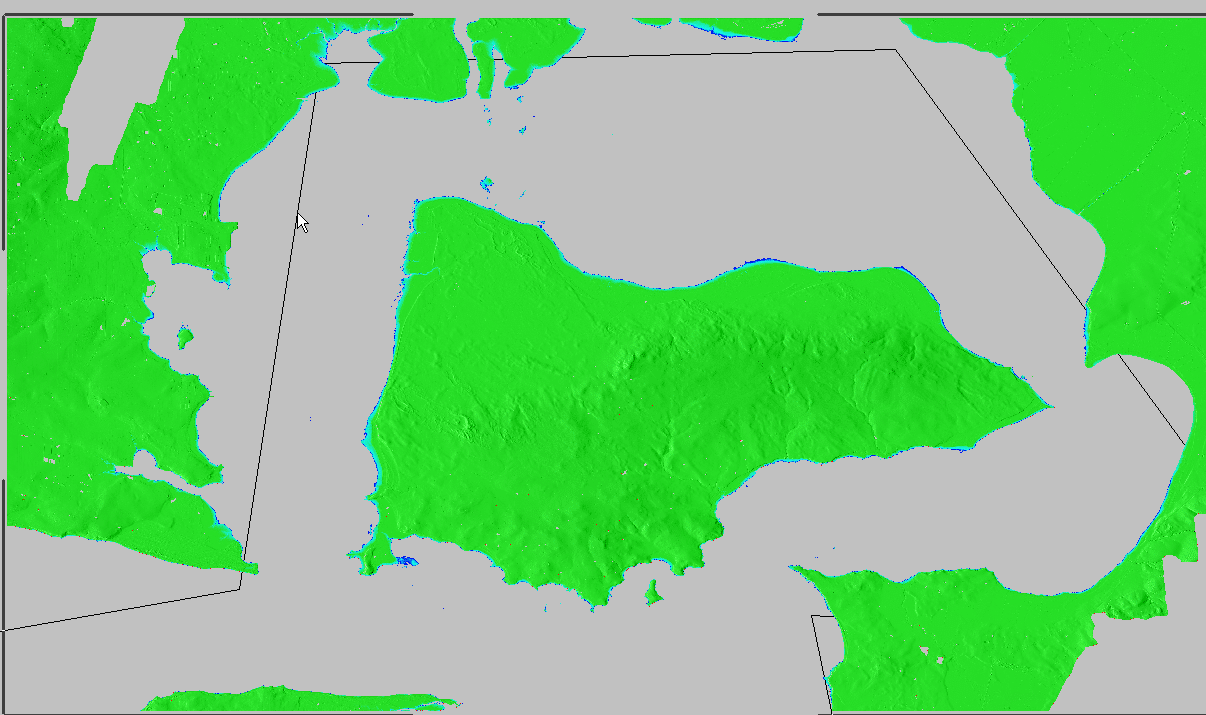
We can export from here in the PNG 16 bit grayscale format Atoll takes, but there’s a catch, negative elevation values and blank data will show up as giant spikes which will totally mess with your propagation modeling.
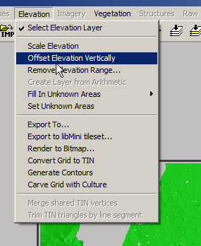
So I found an option to remove elevation data from a set range, but it won’t deal with negative values…
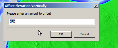
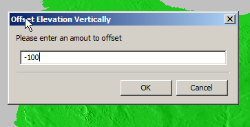
So I found another option in the elevation menu to offset elevation vertically, I added 100 ft (It’s all in ft for some reason) to everything which meant my elevation data that was previously negative was now just under 100.
So if an area was -1ft before it was now 99ft.
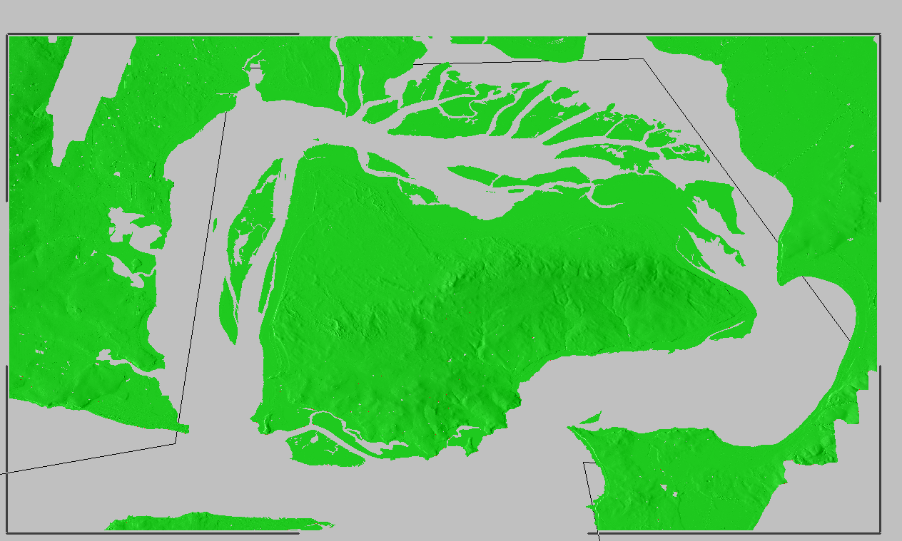
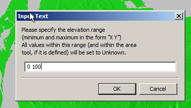
Now I was able to use the remove range for anything from 0 100 ft (previously sea level)
Now my map only shows data above sea level
Now I offset the elevation vertically again and remove 100ft so we get back to real values
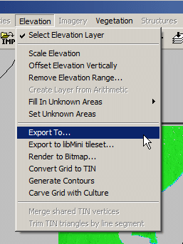
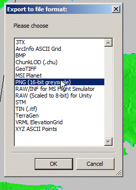
Now I was able to export the elevation data from the Elevation -> Export to menu
Atoll seems to like PNG 16 bit greyscale so that’s what we’ll feed it.
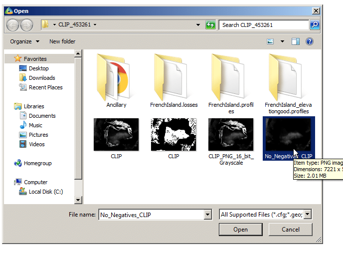
In Atoll we’ll select File -> Import and open the PNG we just generated.
Data type will be Altitude, Pixel size is 5m (as denoted in email / dataset metadata).
Next question is offset, which took me a while to work out…
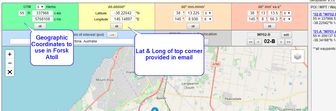
The email has the Lat & Long but Atoll deals in WGS co-ordinates,
Luckily the GeoPlanner website allows you to enter the lat & long of the top corner and get the equivalent West and North values for the UTM dataum.
Enter these values as your coordinates and you’re sorted.
I can even able a Map layer and confirm it lines up:
I started working on a private LTE project a while ago; RAN hardware (eNodeBs) were on the way, down to a shortlist of a few EPC platforms, but I still needed USIMs before anyone was connecting to the network.
So why are custom USIMs a requirement? Can’t you just use any old USIM/SIMs?
For roaming to work between carriers they’ve got to have their HSS / DRA connecting to the DRA or HSS of other carriers, to allow roaming subscribers to access the network, otherwise they too would fall foul of the mutual network authentication and the USIM wouldn’t connect to the network.
The first USIMs I purchased online through a popular online marketplace with a focus on connecting you to Chinese manufacturers. They listed a package of USIMS, a USB reader/writer that supported all the standard USIM form factors and the software to program it, which I purchased.
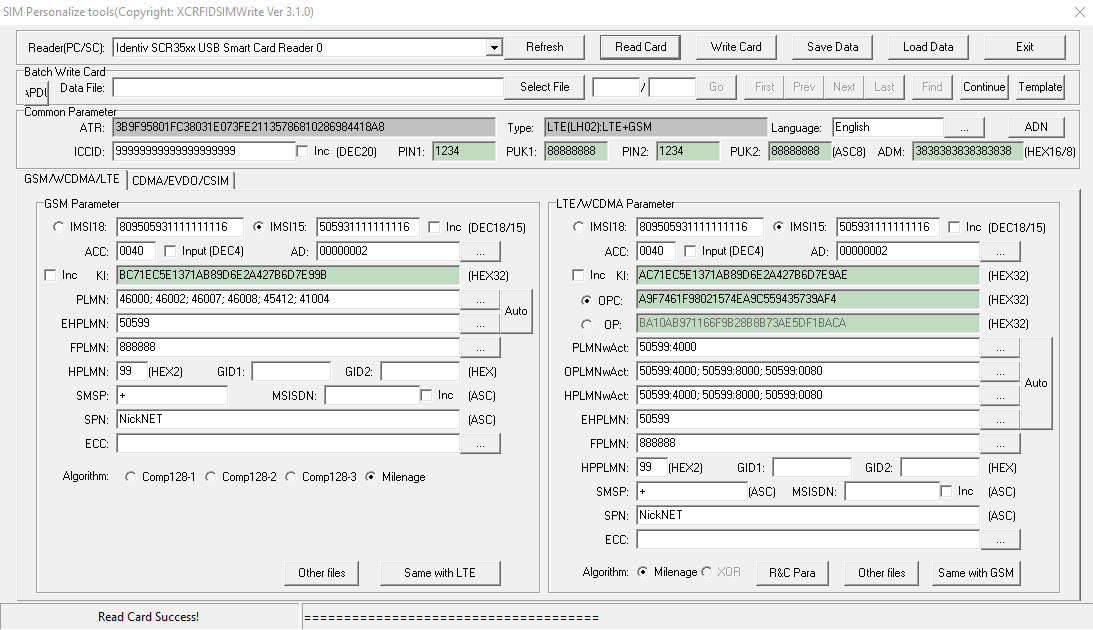
The USIMs worked fairly well – They are programmable via a card reader and software that, although poorly translated/documented, worked fairly well.
USIM Programming Interface
K and OP/OPc values could be written to the card but not read, while the other values could be read and written from the software, the software also has the ability to sequentially program the USIMs to make bulk operations easier. The pricing worked out about $8 USD per USIM, which although expensive for the quantity and programmable element is pretty reasonable.
Every now and then the Crypto values for some reason or another wouldn’t get updated, which is exactly as irritating as it sounds.
Pretty quickly into the build I learned the USIMs didn’t include an ISIM service on the card, ISIM being the service that runs on the UCCID responsible for IMS / VoLTE authentication.
Again I went looking and reached out to a few manufacturers of USIMs.
The big vendors, Gemalto, Kona, etc, weren’t interested in providing USIMs in quantities less than 100,000 and their USIMs came from the factory pre-programmed, meaning the values could only be changed through remote SIM provisioning, a form of black magic.
In the end I reached out to an OEM manufacturer from China who provided programmable USIM / ISIMs for less than I was paying on the online marketplace and at any quantity I wanted with custom printing options, allocated ICCIDs, etc.
The non-programmable USIMs worked out less than $0.40 USD each in larger quantities, and programmable USIM/ISIMs for about $5 USD.
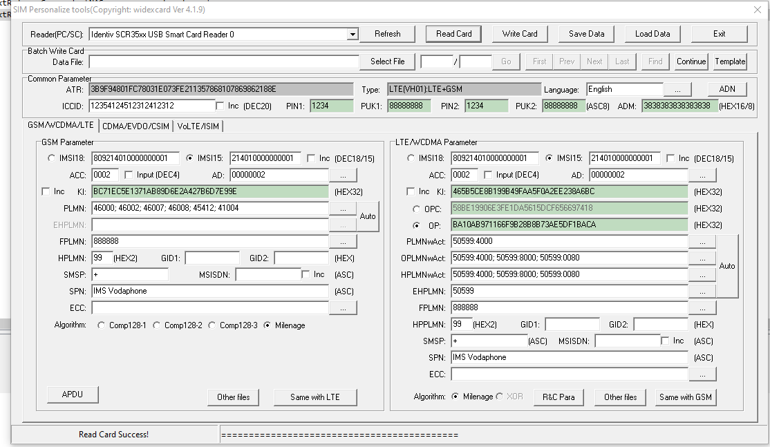
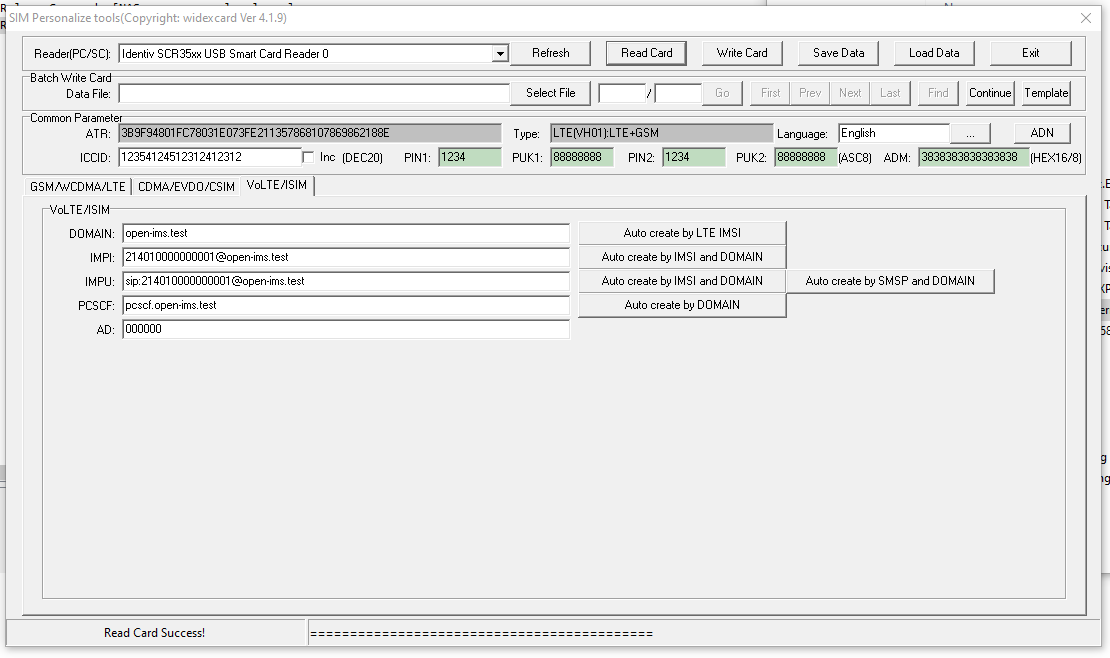
The software was almost identical except for the additional tab for ISIM operations.
USIM / ISIM programmingISIM parameters
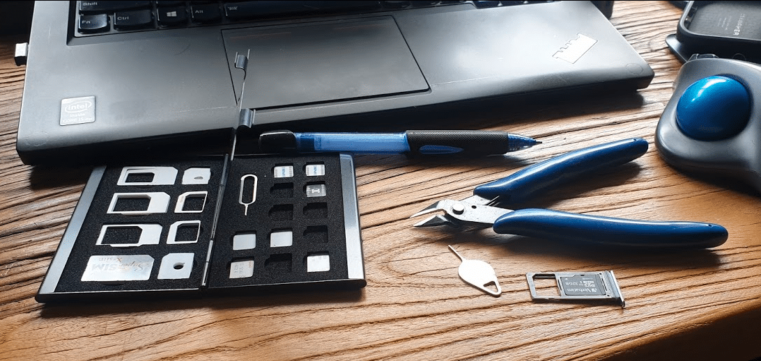
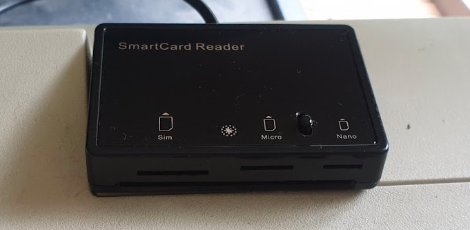
Smart Card Readers
In theory this software and these USIMs could be programmed by any smart card reader.
In practice, the fact that the ISO standard smart card is the same size as a credit card, means most smart card readers won’t fit the bill.
I tried a few smart card readers, from the one built into my Thinkpad, to a Bluedrive II from one of the USIM vendors, in the end the MCR3516 Smart Card Reader which reads 4FF USIMs (Standard ISO size smart card, full size SIM, Micro SIM and Nano SIM form factors, which saved on so much mucking about with form factor adapters etc.
4FF Smart Card Reader for programming SIM/USIM/ISIM
Future Projects
I’ve got some very calls “Multi Operator Neutral Host” (MoNEH) USIMs from the guys at Telet Research I’m looking forward to playing with,
eSIMs are on my to-do list too, and the supporting infrastructure, as well as Over the Air updating of USIMs.
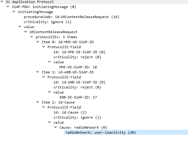
In order to keep radio resources free, if a UE doesn’t send or receive data for a predefined threshold, it’ll detach from the network and call back to Idle mode.
If the UE has data to send to the network, the UE will re-attach to the network, whereas if the network has data to send to the UE, it’ll Page the UE in the tracking area it’s currently in, the UE is always listening for it’s identifier (s-TMSI) on the paging channel, and if it hears it’s identifier called, the UE will re-attach.
I’ve also attached a PCAP file of the packet flow between the eNB and the MME.
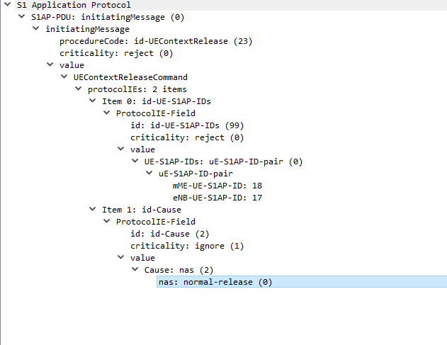
The next packet is sent from the MME back to the eNB confirming UE is releasing from the network.
UEContextReleaseCommand
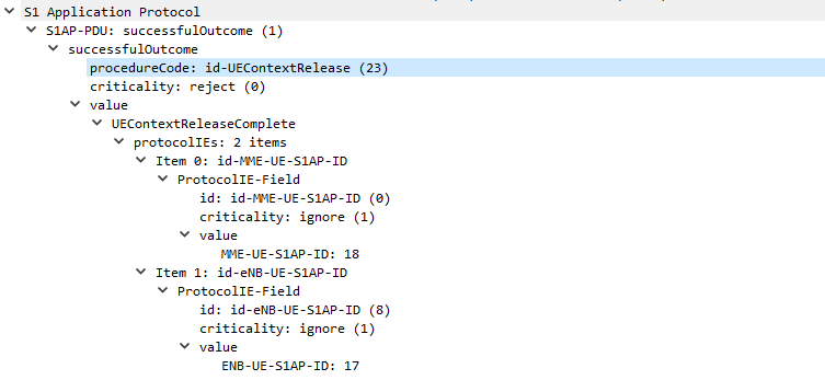
UEContextReleaseComplete
Finally after the UE has released it’s radio resources the eNB sends a UEContextReleaseComplete so the MME knows the UE is now in Idle state and will need to be paged.