The Network Repository Function plays matchmaker to all the elements in our 5G Core.
For our 5G Service-Based-Architecture (SBA) we use Service Based Interfaces (SBIs) to communicate between Network Functions. Sometimes a Network Function acts as a server for these interfaces (aka “Service Producer”) and sometimes it acts as a client on these interfaces (aka “Service Consumer”).
For service consumers to be able to find service producers (Clients to be able to find servers), we need a directory mechanism for clients to be able to find the servers to serve their needs, this is the role of the NRF.
With every Service Producer registering to the NRF, the NRF has knowledge of all the available Service Producers in the network, so when a Service Consumer NF comes along (Like an AMF looking for UDM), it just queries the NRF to get the details of who can serve it.
Basic Process – NRF Registration
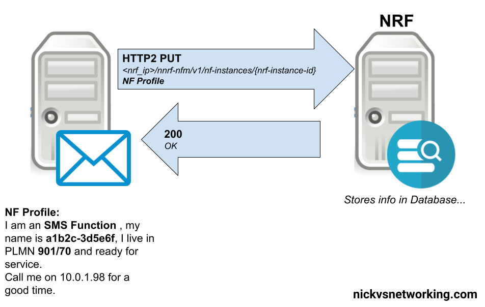
In order to be found, a service producer NF has to register with the NRF, so the NRF has enough info on the service-producer to be able to recommend it to service-consumers.
This is all the basic info, the Service Based Interfaces (SBIs) that this NF serves, the PLMN, and the type of NF.
The NRF then stores this information in a database, ready to be found by SBI Service Consumers.
This is achieved by the Service Producing NF sending a HTTP2 PUT to the NRF, with the message body containing all the particulars about the services it offers.
Simplified example of an SMSc registering with the NRF in a 5G Core
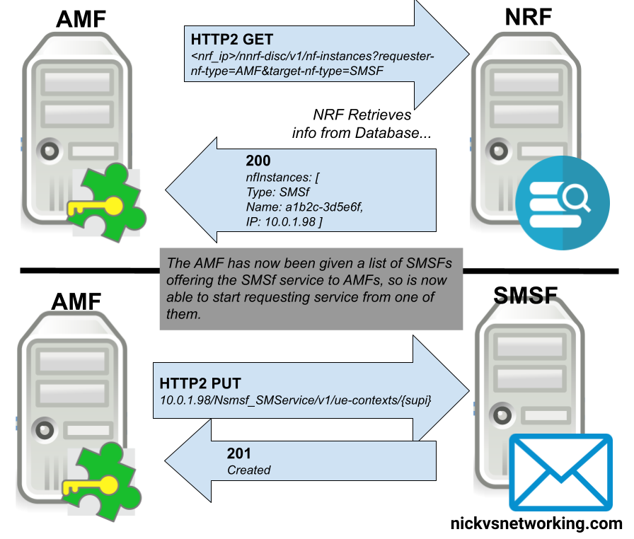
Basic Process – NRF Discovery
With an NRF that has a few SBI Service Producers registered in it, we can now start querying it from SBI Service Consumers, to find SBI Service Producers.
The SBI Service Consumer looking for a SBI Service Producer, queries the NRF with a little information about itself, and the SBI Service Producer it’s looking for.
For example a SMF looking for a UDM, sends a request like:
There’s no such thing as a free lunch, and 5G is the same – services running through a 5G Standalone core need to be billed.
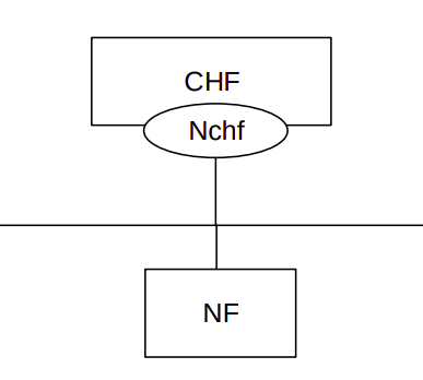
In 5G Core Networks, the SMF (Session Management Function) reaches out to the CHF (Charging Function) to perform online charging, via the Nchf_ConvergedCharging Service Based Interface (aka reference point).
Like in other generations of core mobile networks, Credit Control in 5G networks is based on 3 functions: Requesting a quota for a subscriber from an online charging service, which if granted permits the subscriber to use a certain number of units (in this case data transferred in/out). Just before those units are exhausted sending an update to request more units from the online charging service to allow the service to continue. When the session has ended or or subscriber has disconnected, a termination to inform the online charging service to stop billing and refund any unused credit / units (data).
Initial Service Creation (ConvergedCharging_Create)
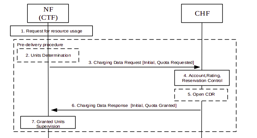
When the SMF needs to setup a session, (For example when the AMF sends the SMF a Nsmf_PDU_SessionCreate request), the CTF (Charging Trigger Function) built into the SMF sends a Nchf_ ConvergedCharging_Create (Initial, Quota Requested) to the Charging Function (CHF).
Because the Nchf_ConvergedCharging interface is a Service Based Interface this is carried over HTTP, in practice, this means the SMF sends a HTTP post to http://yourchargingfunction/Nchf_ConvergedCharging/v1/chargingdata/
Obviously there’s some additional information to be shared rather than just a HTTP post, so the HTTP post includes the ChargingDataRequest as the Request Body. If you’ve dealt with Diameter Credit Control you may be expecting the ChargingDataRequest information to be a huge jumble of nested AVPs, but it’s actually a fairly short list:
The subscriberIdentifier (SUPI) is included to identify the subscriber so the CHF knows which subscriber to charge
The nfConsumerIdentification identifies the SMF generating the request (The SBI Consumer)
The invocationTimeStamp and invocationSequenceNumber are both pretty self explanatory; the time the request is sent and the sequence number from the SBI consumer
The notifyUri identifies which URI should receive subsequent notifications from the CHF (For example if the CHF wants to terminate the session, the SMF to send that to)
The multipleUnitUsage defines the service-specific parameters for the quota being requested.
The triggers identifies the events that trigger the request
Of those each of the fields should be pretty self explanatory as to their purpose. The multipleUnitUsage data is used like the Service Information AVP in Diameter based Credit Control, in that it defines the specifics of the service we’re requesting a quota for. Inside it contains a mandatory ratingGroup specifying which rating group the CHF should use, and optionally requestedUnit which can define either the amount of service units being requested (For us this is data in/out), or to tell the CHF units are needed. Typically this is used to define the amount of units to be requested.
On the amount of units requested we have a bit of a chicken-and-egg scenario; we don’t know how many units (In our case the units is transferred data in/out) to request, if we request too much we’ll take up all the customer’s credit, potentially prohibiting them from accessing other services, and not enough requested and we’ll constantly slam the CHF with requests for more credit. In practice this value is somewhere between the two, and will vary quite a bit.
Based on the service details the SMF has put in the Nchf_ ConvergedCharging_Create request, the Charging Function (CHF) takes into account the subscriber’s current balance, credit control policies, etc, and uses this to determine if the Subscriber has the required balances to be granted a service, and if so, sends back a 201 CREATED response back to the Nchf_ConvergedCharging_Create request sent by the CTF inside the SMF.
This 201 CREATED response is again fairly clean and simple, the key information is in the multipleQuotaInformation which is nested within the ChargingDataResponse, which contains the finalUnitIndication defining the maximum units to be granted for the session, and the triggers to define when to check in with CHF again, for time, volume and quota thresholds.
And with that, the service is granted, the SMF can instruct the UPF to start allowing traffic through.
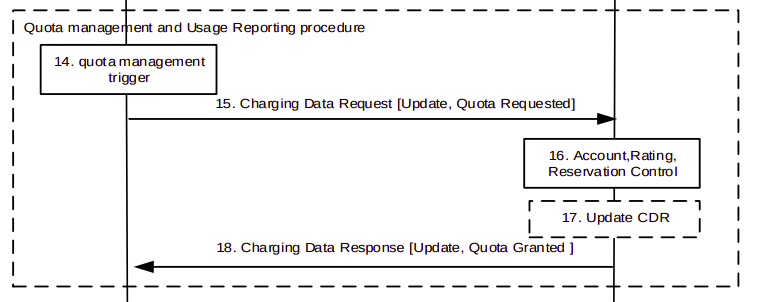
Update (ConvergedCharging_Update)
Once the granted units / quota has been exhausted, the Update (ConvergedCharging_Update) request is used for requesting subsequent usage / quota units. For example our Subscriber has used up all the data initially allocated but is still consuming data, so the SMF sends a Nchf_ConvergedCharging_Update request to request more units, via another HTTP post, to the CHF, with the requested service unit in the request body in the form of ChargingDataRequest as we saw in the initial ConvergedCharging_Create.
If the subscriber still has credit and the CHF is OK to allow their service to continue, the CHF returns a 200 OK with the ChargingDataResponse, again, detailing the units to be granted.
This procedure repeats over and over as the subscriber uses their allocated units.
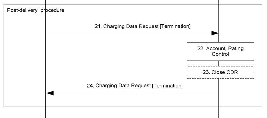
Release (ConvergedCharging_Release)
Eventually when our subscriber disconnects, the SMF will generate a Nchf_ConvergedCharging_Release request, detailing the data the subscriber used in the ChargingDataRequest in the body, to the CHF, so it can refund any unused credits.
The CHF sends back a 204 No Content response, and the procedure is completed.
More Info
If you’ve had experience in Diameter credit control, this simple procedure will be a breath of fresh air, it’s clean and easy to comprehend, If you’d like to learn more the 3GPP specification docs on the topic are clear and comprehensible, I’d suggest:
TS 132 290 – Short overview of charging mechanisms
TS 132 291 – Specifics of the Nchf_ConvergedCharging interface
The common 3GPP charging architecture is specified in TS 32.240
TS 132 291 – Overview of components and SBIs inc Operations
Early on as subscriber trunk dialing and automated time-based charging was introduced to phone networks, engineers were faced with a problem from Payphones.
Previously a call had been a fixed price, once the caller put in their coins, if they put in enough coins, they could dial and stay on the line as long as they wanted.
But as the length of calls began to be metered, it means if I put $3 of coins into the payphone, and make a call to a destination that costs $1 per minute, then I should only be allowed to have a 3 minute long phone call, and the call should be cutoff before the 4th minute, as I would have used all my available credit.
Conversely if I put $3 into the Payphone and only call a $1 per minute destination for 2 minutes, I should get $1 refunded at the end of my call.
We see the exact same problem with prepaid subscribers on IMS Networks, and it’s solved in much the same way.
In LTE/EPC Networks, Diameter is used for all our credit control, with all online charging based on the Ro interface. So let’s take a look at how this works and what goes on.
Generic 3GPP Online Charging Architecture
3GPP defines a generic 3GPP Online charging architecture, that’s used by IMS for Credit Control of prepaid subscribers, but also for prepaid metering of data usage, other volume based flows, as well as event-based charging like SMS and MMS.
Network functions that handle chargeable services (like the data transferred through a P-GW or calls through a S-CSCF) contain a Charging Trigger Function (CTF) (While reading the specifications, you may be left thinking that the Charging Trigger Function is a separate entity, but more often than not, the CTF is built into the network element as an interface).
The CTF is a Diameter application that generates requests to the Online Charging Function (OCF) to be granted resources for the session / call / data flow, the subscriber wants to use, prior to granting them the service.
So network elements that need to charge for services in realtime contain a Charging Trigger Function (CTF) which in turn talks to an Online Charging Function (OCF) which typically is part of an Online Charging System (AKA OCS).
For example when a subscriber turns on their phone and a GTP session is setup on the P-GW/PCEF, but before data is allowed to flow through it, a Diameter “Credit Control Request” is generated by the Charging Trigger Function (CTF) in the P-GW/PCEF, which is sent to our Online Charging Server (OCS).
The “Credit Control Answer” back from the OCS indicates the subscriber has the balance needed to use data services, and specifies how much data up and down the subscriber has been granted to use.
The P-GW/PCEF grants service to the subscriber for the specified amount of units, and the subscriber can start using data.
This is a simplified example – Decentralized vs Centralized Rating and Unit Determination enter into this, session reservation, etc.
The interface between our Charging Trigger Functions (CTF) and the Online Charging Functions (OCF), is the Ro interface, which is a Diameter based interface, and is common not just for online charging for data usage, IMS Credit Control, MMS, value added services, etc.
3GPP define a reference online-charging interface, the Ro interface, and all the application-specific interfaces, like the Gy for billing data usage, build on top of the Ro interface spec.
Basic Credit Control Request / Credit Control Answer Process
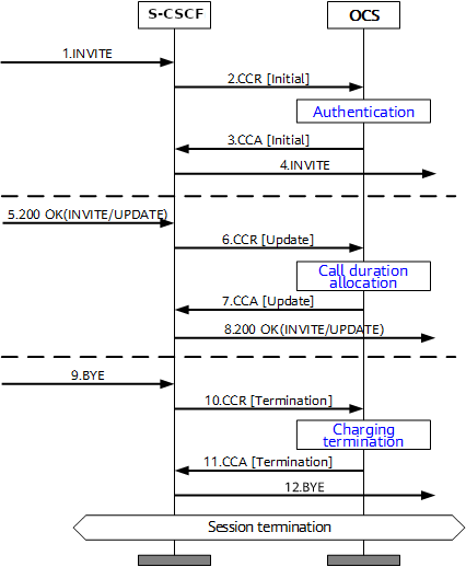
This example will look at a VoLTE call over IMS.
When a subscriber sends an INVITE, the Charging Trigger Function baked in our S-CSCF sends a Diameter “Credit Control Request” (CCR) to our Online Charging Function, with the type INITIAL, meaning this is the first CCR for this session.
The CCR contains the Service Information AVP. It’s this little AVP that is where the majority of the magic happens, as it defines what the service the subscriber is requesting. The main difference between the multitude of online charging interfaces in EPC networks, is just what the service the customer is requesting, and the specifics of that service.
For this example it’s a voice call, so this Service Information AVP contains a “IMS-Information” AVP. This AVP defines all the parameters for a IMS phone call to be online charged, for a voice call, this is the called-party, calling party, SDP (for differentiating between voice / video, etc.).
It’s the contents of this Service Information AVP the OCS uses to make decision on if service should be granted or not, and how many service units to be granted. (If Centralized Rating and Unit Determination is used, we’ll cover that in another post) The actual logic, relating to this decision is typically based on the the rating and tariffing, credit control profiles, etc, and is outside the scope of the interface, but in short, the OCS will make a yes/no decision about if the subscriber should be granted access to the particular service, and if yes, then how many minutes / Bytes / Events should be granted.
In the received Credit Control Answer is received back from our OCS, and the Granted-Service-Unit AVP is analysed by the S-CSCF. For a voice call, the service units will be time. This tells the S-CSCF how long the call can go on before the S-CSCF will need to send another Credit Control Request, for the purposes of this example we’ll imagine the returned value is 600 seconds / 10 minutes.
The S-CSCF will then grant service, the subscriber can start their voice call, and start the countdown of the time granted by the OCS.
As our chatty subscriber stays on their call, the S-CSCF approaches the limit of the Granted Service units from the OCS (Say 500 seconds used of the 600 seconds granted). Before this limit is reached the S-CSCF’s CTF function sends another Credit Control Request with the type UPDATE_REQUEST. This allows the OCS to analyse the remaining balance of the subscriber and policies to tell the S-CSCF how long the call can continue to proceed for in the form of granted service units returned in the Credit Control Answer, which for our example can be 300 seconds.
Eventually, and before the second lot of granted units runs out, our subscriber ends the call, for a total talk time of 700 seconds.
But wait, the subscriber been granted 600 seconds for our INITIAL request, and a further 300 seconds in our UPDATE_REQUEST, for a total of 900 seconds, but the subscriber only used 700 seconds?
The S-CSCF sends a final Credit Control Request, this time with type TERMINATION_REQUEST and lets the OCS know via the Used-Service-Unit AVP, how many units the subscriber actually used (700 seconds), meaning the OCS will refund the balance for the gap of 200 seconds the subscriber didn’t use.
If this were the interface for online charging of data, we’d have the PS-Information AVP, or for online charging of SMS we’d have the SMS-Information, and so on.
The architecture and framework for how the charging works doesn’t change between a voice call, data traffic or messaging, just the particulars for the type of service we need to bill, as defined in the Service Information AVP, and the OCS making a decision on that based on if the subscriber should be granted service, and if yes, how many units of whatever type.
While we’ve covered the Update Location Request / Response, where an MME is able to request subscriber data from the HSS, what about updating a subscriber’s profile when they’re already attached? If we’re just relying on the Update Location Request / Response dialog, the update to the subscriber’s profile would only happen when they re-attach.
We need a mechanism where the HSS can send the Request and the MME can send the response.
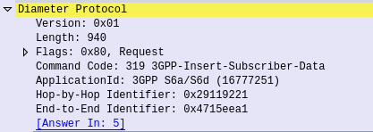
This is what the Insert Subscriber Data Request/Response is used for.
Let's imagine we want to allow a subscriber to access an additional APN, or change an AMBR values of an existing APN;

We'd send an Insert Subscriber Data Request from the HSS, to the MME, with the Subscription Data AVP populated with the additional APN the subscriber can now access.
Beyond just updating the Subscription Data, the Insert Subscriber Data Request/Response has a few other funky uses.
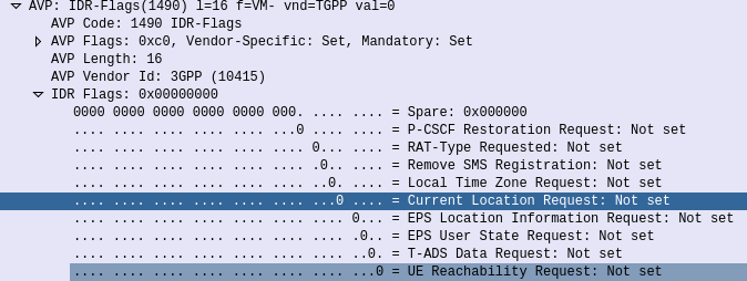
Through it the HSS can request the EPS Location information of a Subscriber, down to the TAC / eNB ID serving that subscriber. It’s not the same thing as the GMLC interfaces used for locating subscribers, but will wake Idle UEs to get their current serving eNB, if the Current Location Request is set in the IDR Flags.
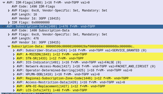
But the most common use for the Insert-Subscriber-Data request is to modify the Subscription Profile, contained in the Subscription-Data AVP,
If the All-APN-Configurations-Included-Indicator is set in the AVP info, then all the existing AVPs will be replaced, if it’s not then everything specified is just updated.
The Insert Subscriber Data Request/Response is a bit novel compared to other S6a requests, in this case it’s initiated by the HSS to the MME (Like the Cancel Location Request), and used to update an existing value.
In the last we covered what ENUM is and how it works, so to take this into a more practical example, I thought I’d share the details of the ENUM server I’ve setup in my lab, and the Docker container I’ve bundled it into.
Inside the Docker container we’ll be running Bind – this post won’t teach you much about Bind, there’s already lots of good information on it elsewhere, but we will cover the parameters involved in setting up ENUM records (NAPTR) for E.164 addresses.
Getting the Environment up and Running
First we’ll need to setup our environment, I’ve published the images for the container to Dockerhub, but we’ll build it from the Dockerfile so you can edit the files and rebuild as you play around:
systemd-resolve on Ubuntu binds to port 53 by default, which can lead to some headaches, so we’ll create a new network in Docker for this to run in, so it doesn’t conflict with anything else you may be running:
And now we’ll run the ENUM container in the enum_playground network and with the IP 172.30.0.2,
docker run -d --rm --name=enum --net=enum_playground --ip=172.30.0.2 enum
Ok, that’s the environment setup, let’s run some queries!
E.164 to SIP URI Resolution with ENUM
In our last post we covered the basics of formatting an E.164 number and querying a DNS server to get it’s call routing information.
Again we’re going to use Dig to query this information. In reality ENUM queries would be run by an endpoint, or software like FreeSWITCH or Kamailio (Spoiler alert, posts on ENUM handling in those coming later), but as we’re just playing Dig will work fine.
So let’s start by querying a single E.164 address, +61355500911
First we’ll reverse it and put full stops / periods between the numbers, to get 1.1.9.0.0.5.5.5.3.1.6
Next we’ll add the e164.arpa prefix, which is the global prefix for ENUM addresses, and presto, that’s what we’ll query – 1.1.9.0.0.5.5.5.3.1.6.e164.arpa
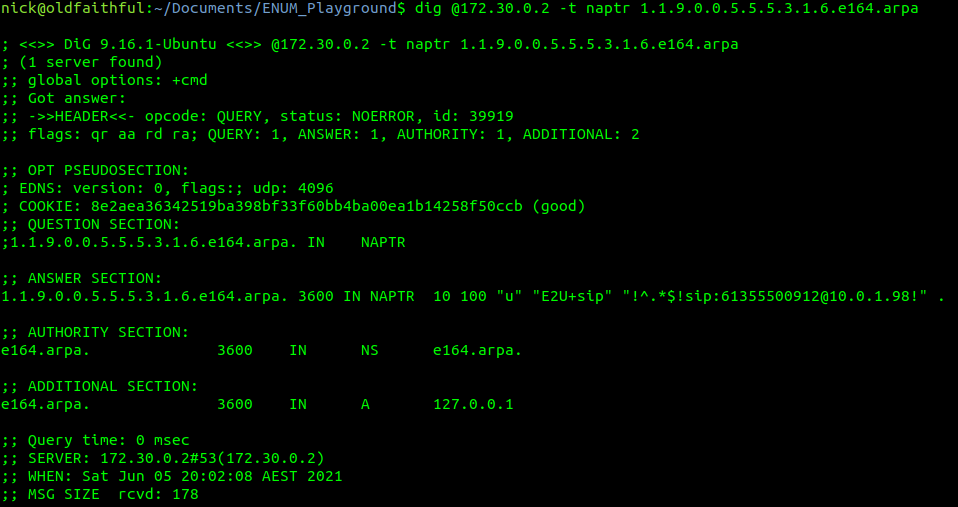
Lastly we’ll feed this into a Dig query against the IP of our container and of type NAPTR,
Next up is the TTL or expiry, in this case it’s 3600 seconds (1 hour), shorter periods allow for changes to propagate / be reflected more quickly but at the expense of more load as results can’t be cached for as long. The class (IN) represents Internet, which is the only class commonly used, even on internal systems.
Then we have the type of record returned, in our case it’s a NAPTR record,
1.1.9.0.0.5.5.5.3.1.6.e164.arpa.3600 IN NAPTR 10 100 "u" "E2U+sip" "!^.*$!sip:[email protected]!" .
After that is the Order, this defines the order in which the rules are to be parsed. Lower numbers are processed first, if no matches then the next lowest, and so on until the highest number is reached, we’ll touch on this in more detail later in this post,
1.1.9.0.0.5.5.5.3.1.6.e164.arpa.3600 IN NAPTR 10 100 "u" "E2U+sip" "!^.*$!sip:[email protected]!" .
The Pref is the processing preference. This is very handy for load balancing, as we can split traffic between hosts with different preferences. We’ll cover this later in this post too.
1.1.9.0.0.5.5.5.3.1.6.e164.arpa.3600 IN NAPTR 10 100 "u" "E2U+sip" "!^.*$!sip:[email protected]!" .
The Flags represent the type of record we’re going to get, for most ENUM traffic this is going to be set to U, to denote a SIP URI with Regex, while the Service value we’ll be looking for will be “E2U+sip” service to identify SIP URIs to route calls to, but could be other values like Email addresses, IM Addresses or PSTN numbers, to be parsed by other applications.
1.1.9.0.0.5.5.5.3.1.6.e164.arpa.3600 IN NAPTR 10 100 "u" "E2U+sip" "!^.*$!sip:[email protected]!" .
Lastly we’ve got the Regex part. Again not going to cover Regex as a whole, just the DNS particulars.
Everything between the first and second ! denotes what we’re searching for, while everything from the second ! to the last ! denotes what we replace it with.
In the below example that means we’re matching ^.* which means starting with (^) any character (.) zero or more times (*), which gets replaced with sip:[email protected],
1.1.9.0.0.5.5.5.3.1.6.e164.arpa.3600 IN NAPTR 10 100"u" "E2U+sip" "!^.*$!sip:[email protected]!" .
How should this be treated?
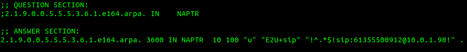
For the first example, a call to the E.164 address of 61355500912 will be first formatted into a domain as per the ENUM requirements (1.1.9.0.0.5.5.5.3.1.6.e164.arpa) and then queried as a NAPTR record against the DNS server,
1.1.9.0.0.5.5.5.3.1.6.e164.arpa.3600 IN NAPTR 10 100"u" "E2U+sip" "!^.*$!sip:[email protected]!" .
Only a single record has been returned so we don’t need to worry about the Order or Preference, and the Regex matches anything and replaces it with the resulting SIP URI of sip:[email protected], which is where we’ll send our INVITE.
Under the Hood
Inside the Repo we cloned earlier, if you open the e164.arpa.db file, things will look somewhat familiar,
The record we just queried is the first example in the Bind config file,
; E.164 Address +61355500911 - Simple no replacement (Resolves all traffic to sip:[email protected])
1.1.9.0.0.5.5.5.3.1.6 IN NAPTR 10 100 "u" "E2U+sip" "!^.*$!sip:[email protected]!" .
The config file is just the domain, class, type, order, preference, flags, service and regex.
Astute readers may have noticed the trailing . which where we can put a replacement domain if Regex is not used, but it cannot be used in conjunction with Regex, so for all our work it’ll just be a single trailing . on each line.
You can (and probably should) change the values in the e164.arpa.db file as we go along to try everything out, you’ll just need to rebuild the container and restart it each time you make a change.
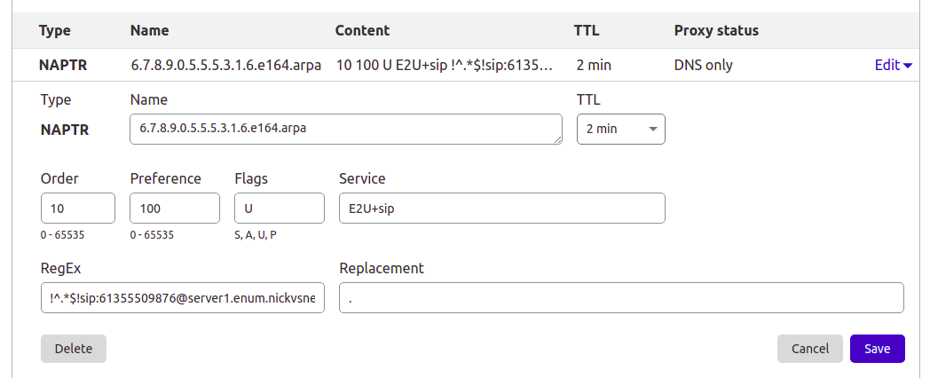
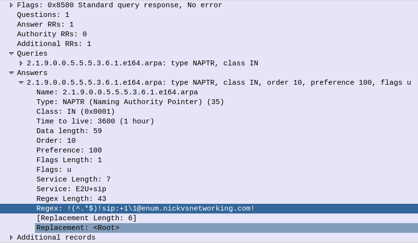
This post is going to focus on Bind, but the majority of modern DNS servers support NAPTR records, so you can use them for ENUM as well, for example I manage the DNS for this site thorough Cloudflare, and I’ve put a screenshot below of an example private ENUM address I’ve added into it.
Setting up a NAPTR record in Cloudflare DNS
Preference to Split Traffic between Servers
So with a firm understanding of a single record being returned, let’s look at how we can use ENUM to cleverly route traffic to multiple hosts.
If we have a pool of servers we may wish to evenly distribute all traffic across them, so that’s how E.164 address +61355500912 is setup – to route traffic evenly (50/50) across two servers.
Querying it with Dig provides the following result:
So as the order value (10) is the same for both records, we can ignore it – there isn’t one value lower than the other.
We can see both records have a preference of 100, in practice, this means they each get 50% of the traffic. The formula for traffic distribution is pretty simple, each server gets the value of it’s preference, divided by the total of all the preferences,
So for server1 it’s preference is 100 and the total of all the preferences combined is 200, so it gets 100/200, which is equivalent to one half aka 50%.
We might have a scenario where we have 3 servers, but one is significantly more powerful than the others, so let’s look at giving more traffic to one server and less to others, this example gets a little more complex but should cement your understanding of how the preference works;
So now 3 servers, again none have a lower order than the other, it’s set to 10 for them all so we can ignore the order,
Next we can see the total of all the priority values is 400,
Server 2 has a priority of 100 so it gets 100/400 total priority, or a quarter of all traffic. Server 1 has the same value, so also gets a quarter of all traffic,
Server 3 however has a priority of 200 so it gets 200/400, or to simplify half of all traffic.
The Bind config for this is:
; E.164 Address +61355500913 - More complex load balance between 3 hosts (25% server1, 25% server2, 50% server3)
3.1.9.0.0.5.5.5.3.1.6 IN NAPTR 10 100 "u" "E2U+sip" "!^.*$!sip:[email protected]!" . 3.1.9.0.0.5.5.5.3.1.6 IN NAPTR 10 100 "u" "E2U+sip" "!^.*$!sip:[email protected]!" .
3.1.9.0.0.5.5.5.3.1.6 IN NAPTR 10 200 "u" "E2U+sip" "!^.*$!sip:[email protected]!" .
Order for Failover
Primarily the purpose of the order is to enable wildcard routes (as we’ll see later) to be overwritten by more specific routes, but a secondary use in some implementations use Order as a way to list the preferences of the SIP URIs to route to. For example we could have two servers, one a primary and the other a standby, with the standby only to be used only if the primary SIP URI was not responding.
E.164 number +61355500914 is setup to return two SIP URIs,
Our DNS client will first use the SIP URI sip:[email protected] as it has the lower order value (10), and if that fails, can try the entry with the next lowest order-value (20) which would be sip:[email protected].
The Bind config for this is:
; E.164 Address +61355500914 - Order example returning multiple SIP URIs to try for failover
4.1.9.0.0.5.5.5.3.1.6 IN NAPTR 10 100 "u" "E2U+sip" "!^.*$!sip:[email protected]!" . 4.1.9.0.0.5.5.5.3.1.6 IN NAPTR 20 100 "u" "E2U+sip" "!^.*$!sip:[email protected]!" .
Wildcards
If we have a 1,000 number block, having to add 1000 individual records can be very tedious. Instead we can use wildcard matching (thanks to the fact we’ve reversed the E.164 address) to match ranges. For example if we have E.164 numbers from +61255501000 to +61255501999 we can add a wildcard entry to match the +61255501x prefix,
I’ve set this up already so let’s lookup the E.164 number +6125501234,
If you look up any other number starting with +6125501 you’ll get the same result, and here’s the Bind config for it:
; Wildcard E.164 Address +61255501* - Wildcard example for all destinations starting with E.164 prefix +61255501x to single destination (sip:[email protected])
; For example E.164 number +6125501234 will resolve to sip:[email protected]
*.1.0.5.5.5.2.1.6 IN NAPTR 100 100 "u" "E2U+sip" "!^.*$!sip:[email protected]!" .
The catch with this is they’re all pointing at the same SIP URI, so we can’t treat the calls differently based on the called number – This is where the Regex magic comes in.
We can use group matching to match a group and fill it in the dialed number into the SIP Request URI, for example:
Will match the E.164 number requested and put it inside sip:[email protected]
The +61255502xxx prefix is setup for this, so if we query +61255502000 (or any other number between +61255502000 and +61255502999) we’ll get the regex query in the resulting record.
Keep in mind DNS doesn’t actually apply the Regex transformation, just shares it, and the client applies the transformation.
; Wildcard example for all destinations starting with E.164 prefix +61255502x to regex filled destination
; For example a request to 61255502000 will return sip:[email protected])
*.2.0.5.5.5.2.1.6 IN NAPTR 100 100 "u" "E2U+sip" "!(^.*$)!sip:+1\\[email protected]!" .
One last thing to keep in mind, is that Wildcard priorities are of any length. This means +612555021 would match as well as +6125550299999999999999. Typically terminating switches drop any superfluous digits, and NU those that are too short, but keep this in mind, that length is not taken into account.
Wildcard Priorities
So with our wildcards in place, what if we wanted to add an exception, for example one number in our 61255502xxx block of numbers gets ported to another carrier and needs to be routed elsewhere?
Easy, we just add another entry for that number being more specific and with a lower order than the wildcard, which is what’s setup for E.164 number +61255502345,
Which does not return the same result as the others that match the wildcard,
Bind config:
; Wildcard example for all destinations starting with E.164 prefix +61255502x to regex filled destination
; For example a request to +61255502000 will return sip:[email protected])
*.2.0.5.5.5.2.1.6 IN NAPTR 100 100 "u" "E2U+sip" "!(^.*$)!sip:+1\\[email protected]!" .

; More specific example with lower order than +6125550x wildcard for E.164 address +61255502345 will return sip:[email protected]
5.4.3.2.0.5.5.5.2.1.6 IN NAPTR 50 100 "u" "E2U+sip" "!^.*$!sip:[email protected]!" .
We can combine all of the tricks we’ve covered here, from statically defined entries, wildcards, regex replacement, multiple entries with multiple orders and preferences, to create really complex routing, using only DNS.
Summary & Next Steps
So by now hopefully you’ve got a fair understanding of how NAPTR and DNS work together to translate E.164 addresses into SIP URIs,
Of course being able to do this manually with Dig and comprehend how it’ll route is only one part of the picture, in the next posts we’ll cover using Kamailio and FreeSWITCH to query ENUM routing information and route traffic to it,
DNS is commonly used for resolving domain names to IP Addresses, and is often described as being like “the phone book of the Internet”.
So what’s the phone book of phone books?
The answer, is (kind of) DNS. With the aid of E.164 number to URI mapping (ENUM), DNS can be used to resolve phone numbers into SIP URIs to route the traffic to.
So what is ENUM?
ENUM allows us to bypass the need for a central switch for routing calls to numbers, and instead, through a DNS lookup, resolve a phone number into a reachable SIP URI that is the ultimate destination for the traffic.
Imagine you want to call a company, you dial the phone number for that company, your phone does a DNS query against the phone number, which returns the SIP URI of the company’s PBX, and your phone sends the SIP INVITE directly to the company’s PBX, with no intermediary party carrying the call.
3GPP have specified ENUM as the prefered mechanism for resolving phone numbers into SIP addresses, and while it’s widespread adoption on the public Internet is still in its early days (See my post on The Sad story of ENUM in Australia) it is increasingly common in IMS networks and inside operator networks.
ENUM allow us to lookup a phone number on a DNS server and find the SIP URI a server that will handle traffic for the phone number, but it’s a bit more complicated than the A or AAAA records you’d use to resolve a website, ENUM relies on NAPTR records.
Let’s look at the steps involved in taking an E.164 number and knowing where to send it.
Step 1 – Reverse the Numbers
We read phone numbers from left to right.
This is because historically the switch needs to get all the long-distance routing sorted first. The switch has to route your call to the exchange that serves that subscriber, which is what all the area codes and prefixes assigned to areas are all about (Throwback to SZU for any old Telco buffs).
For an E.164 number you’ve got a Country Code, Area Code and then the Subscriber Number. The number gets more specific as it goes along.
But getting more specific as you go along is the opposite how how DNS works, millions of domains share the .com suffix, and the unique / specific part is the bits before that.
So the first step in the ENUM process is to reverse the phone number, so let’s take phone number (03) 5550 0912, which in E.164 is +61 3 5550 0912.
As the spaces in the phone numbers are there for the humans, we’ll drop all of them and reverse the number, as DNS is more specific right-to-left, so we end up with
2.1.9.0.0.5.5.5.3.1.6
Step 2 – Add the Suffix
The ITU ENUM specifies the suffix e164.arpa be assigned for public ENUM entries. Private ENUM deployments may use their own suffix, but to make life simple I’m going to use e164.arpa as if it were public.
So we’ll append the e164.arpa domain onto our reversed and formatted E.164 phone number:
2.1.9.0.0.5.5.5.3.1.6.e164.arpa
Step 3 – Query it
Next we’ll run a Naming Authority Pointer (NAPTR) query against the domain, to get back a list of records for that number.
DNS is a big topic, and NAPTR and SRV takes up a good chunk of it, but what you need to know is that by using NAPTR we’re not limited to just a single response, we could have a weighted pool of servers handling traffic for this phone number, and be able to control load through the use of NAPTR, amongst other things.
DNS NAPTR QueryDNS NAPTR Response
Of course, if our phone can query the public NAPTR records, then so can anyone else, so we can just use a tool like Dig to query the record ourselves,
In the answers section I’ve setup this DNS server to only return a single response, with the regex SIP URI to use, in my case that’s sip:[email protected]
You’ll obviously need to replace the DNS server with your DNS server, and the query with the reversed and formatted version of the E.164 number you wish to query.
Step 4 – Send SIP traffic
After looking at the NAPTR records returned and using the weight and priority to determine which server/s to send to first, our phone forwards an INVITE to the URI returned in the NAPTR record.
How to interpret the returned results?
The first thing to keep in mind when working with ENUM is multiple records being returned is supported, and even encouraged.
NAPTR results return 7 fields, which define how it should be handled.
The host part is fairly obvious, and defines the host / DNS entry we’re talking about.
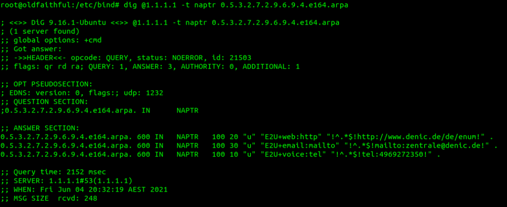
The Service defines what type of service this is. ENUM can be expanded beyond just voice, for example you may want to also return an email address or IM address as well as a SIP Address on an ENUM query, which you can do. By default voice uses the “E2U+sip” service to identify SIP URIs to route calls to, so in this context that’s what we’re interested in, but keep in mind there are other types out there,
Example ENUM query against a phone number showing other types of services (Email & Web)
The Order simply defines the order in which the rules are to be parsed. Lower numbers are processed first, if no matches then the next lowest, and so on until the highest number is reached.
The Pref is the processing preference. For load balancing 50/50 between two sites say a Melbourne and Sydney site, we’d return two results, with the same Order, and the same Pref, would see traffic split 50/50 between the two sites. We could split this further, a Pref value of 10 for Melbourne, 10 for Sydney, 5 for Brisbane and 5 for Perth would see 33% of calls route to Melbourne, 33% of calls route to Sydney, 16.5% of calls route to Brisbane and 16.5% of calls route to Perth. This is because we’d have a total preference value of 30, and the individual preference for each entry would work out as the fraction of the total (ie Pref 10 out of 30 = 10/30 or 33.3%).
The Flags denote the type of record we’re going to get, for most ENUM traffic this is going to be set to U, to denote a SIP URI with Regex.
The regexp field contains our SIP URI in the form of a Regular expression, which can include pattern matching and replacement. This is most commonly used to fill in the phone number into the SIP URI, for example instead of hardcoding the phone number into the response, we could use a Regular expression to fill in the requested number into the SIP URI.
If you’re looking to implement ENUM for an internal network, great, I’ll have some more posts here over the next few weeks covering off configuration of a DNS server to support ENUM lookups, and using Kamailio to lookup ENUM routes.
In terms of public ENUM, while many carriers are using ENUM inside their networks, public adoption of ENUM in most markets has been slow, for a number of reasons.
Many incumbent operators have been reluctant to embrace public ENUM as their role as an operator would be relegated to that of a Domain registrar. Additionally, there’s real security risks involved in moving to ENUM – opening your phone system up to the world to accept inbound calls from anywhere. This could lead to DOS-style attacks of flooding phone numbers with automatically generated traffic, privacy risks and even less validation in terms of caller ID trust.
RIPE maintains the EnumData.org website listing the status of ENUM for each country / region.
We’ve covered SMS in the past, but MMS is a different kettle of fish.
Let’s look at how the call flow goes, when Bob wants to send a picture to Alice.
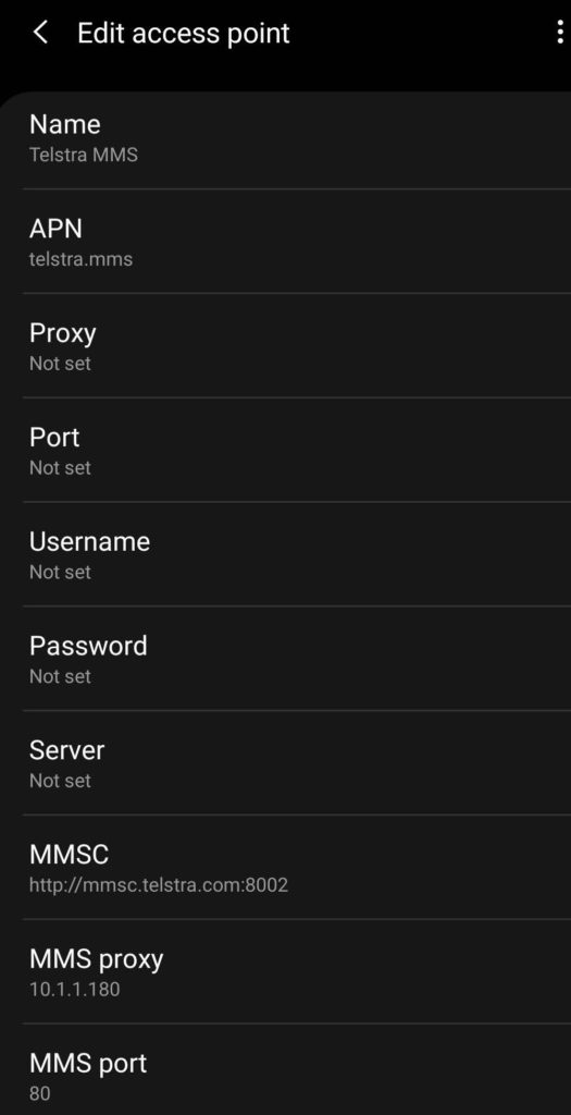
Before Bob sends the MMS, his phone will have to be setup with the correct settings to send MMS. Sometimes this is done manually, for others it’s done through the Carrier provisioning SMS that preloads the settings, and for others it’s baked in based on the Android Carrier settings XML,
APN settings for Telstra in Australia for MMS
It’s made up of the APN to send MMS traffic over, the MMSC address (Multimedia Message Switching Center) and often an MMS proxy and port combination for where the traffic will actually go.
Message Flow – Bob to MMSC (Mobile Originated MMS)
Bob opens his phone, creates a new message to Alice, selects the picture (or other multimedia filetype) to send to her and hits the send button.
For starters, MMS has a file size limit, like MTU it’s not advertised, so you don’t know if you’ve hit it, so rather like MTU is a “lowest has the highest success of getting through” rule. So Bob’s phone will most likely scale the image down to fit inside 300K.
Next Bob’s phone knows it has an MMS to send, for this is opens up a new bearer on the MMS APN, typically called MMS, but configured in the phone by Bob.
Why use a separate APN for sending 300K of MMS traffic? Once upon a time mobile data was expensive. By having a separate APN just for MMS traffic (An APN that could do nothing except send / receive MMS) allowed easier billing / tariffing of data, as MMS traffic was sent over a APN which was unmetered.
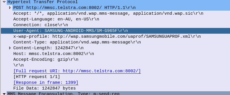
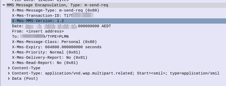
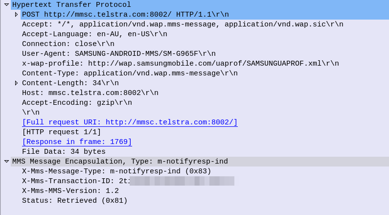
After the bearer is setup on the MMS APN, Bob’s phone begins crafting a HTTP 1.1 Post to be sent to the MMSC. The content type of this request will be application/vnd.wap.mms-message and the body of the HTTP post will be made up of MMS Message Encapsulation, with the body containing the picture he wants to send to Alice.
Note: Historically Wireless Session Protocol (WSP) was used in lieu of HTTP. These clients would now need a WAP gateway to translate into HTTP.
This HTTP Post is then sent to the MMSC Address, or, if present, the MMSC Proxy address. This traffic is sent over the MMS APN that we just brought up.
HTTP POST Headers for the MO MMS MessageMMS Message Encapsulation from MO MMS Message
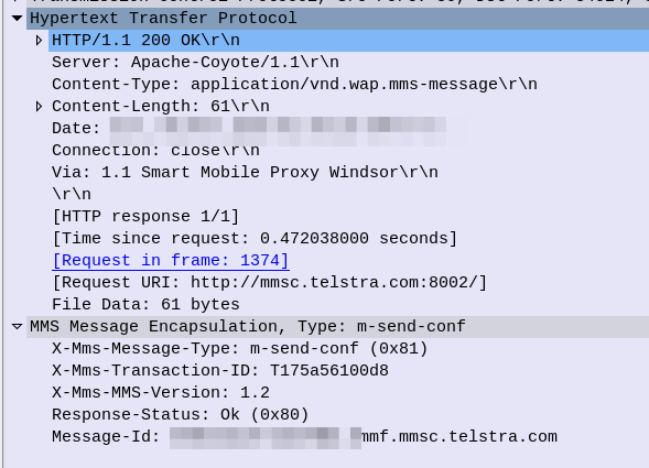
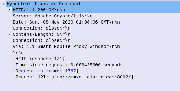
The MMSC receives this information, and then, if all was successful, responds with a 200 OK,
200 OK response to MO MMS Message
So now the MMSC has the information from Bob, let’s flip over to Alice.
Message Flow – MMSC to Alice (Mobile Terminated MMS)
For the purposes of simplicity, we’re going to rule out the MMSC from doing clever things like converting the media, accepting email (SMPP) as MMS, etc, etc. Instead we’re going to assume Alice and Bob are on the same Network, and our MMSC is just doing store-and-forward.
The MMSC will look at the To address in the MMS Message Encapsulation of the request Bob sent, to determine that this message is destined for Alice.
The MMSC will load the media content (photo) sent by Bob destined for Alice and serve it via HTTP. The MMSC generates a random URL to serve it this particular file on, with each MMS the MMSC handles being assigned a random URL containing the media content.
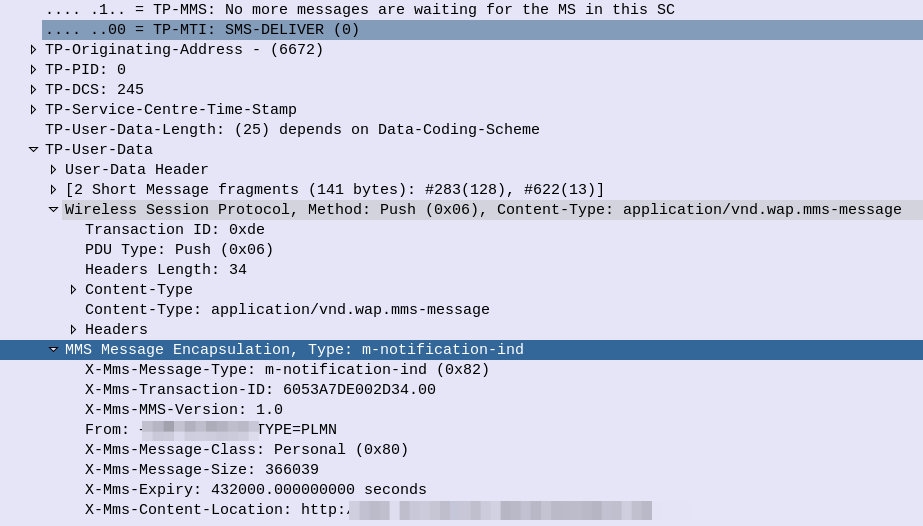
Next the MMSC will need to tell Alice’s phone, that she has an MMS waiting for her. This is done by generating an SMS to send to Alice’s phone,
The user-data of this SMS is the Wireless Session Protocol with the method PUSH – Aka WAP Push.
SMS alerting the user of an MMS waiting for delivery
This specially encoded SMS is parsed by the Alice’s phone, which tells the her there is an MMS message waiting for her.
On some operating systems this is pulled automatically, on others, users need to select “Download” to actually get the file.
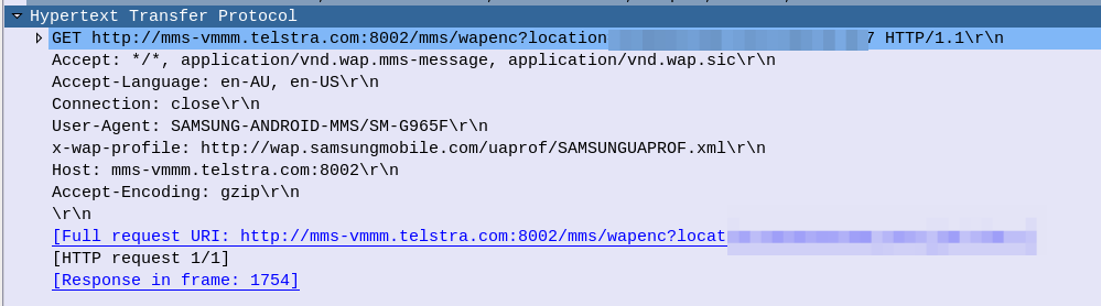
The UE then just runs an HTTP get to the address in the X-Mms-Content-Location: Header to pull the multimedia content that Bob sent.
HTTP GET from Alice’s Phone / UE to retrieve MMS sent by Bob (MT-MMS)
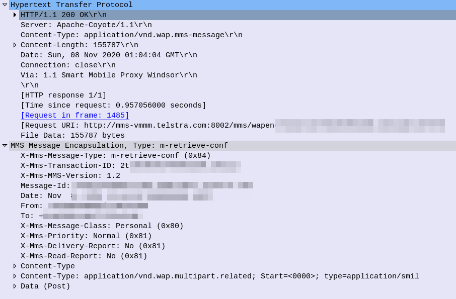
All going well the URL is valid and Alice’s phone retrieves the message, getting a 200 OK back from the server with the message content.
HTTP Response (200 OK) for MT-MMS, sent by the MMSC to Alice’s phone with the MMS Body
So now Alice’s phone has the MMS content and renders it on the screen, Alice can see the Photo Bob sent her.
Lastly Alice’s phone sends a HTTP POST again to the MMSC, this time indicating the message status is “Retrieved”,
And to close everything off the MMSC confirms receipt of the Retrieved status with a 200 OK, and we are done.
What didn’t we cover?
So that’s a basic MMS message flow, but there’s a few parts we didn’t cover.
The overall architecture beyond just the store-and forward behaviour, charging and authentication we didn’t cover. So let’s look at each of these points.
Overall Architecture
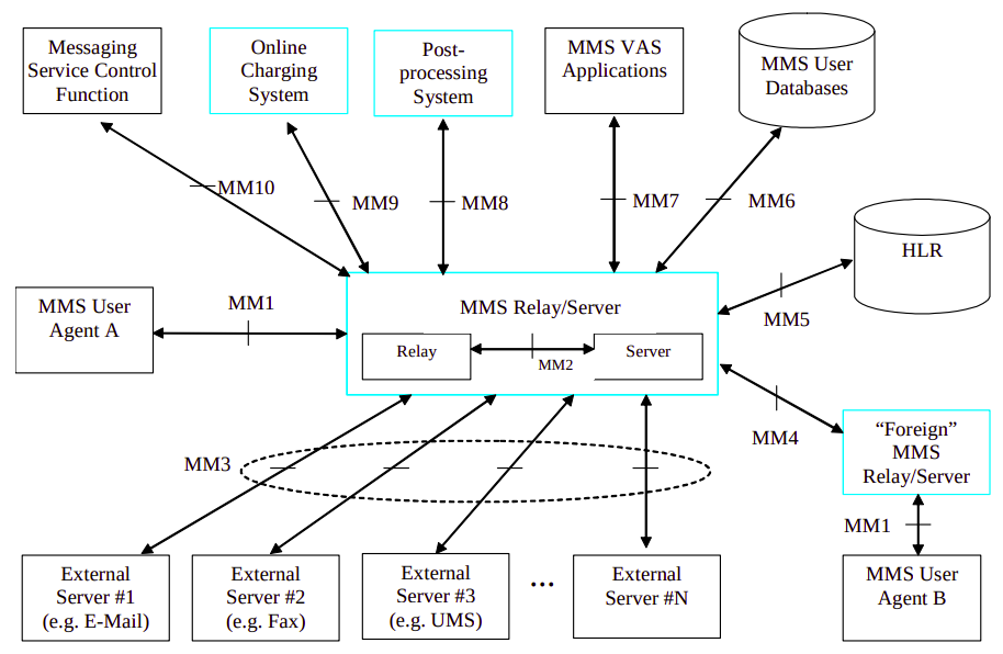
What we just covered what what’s defined as the MM1 interface.
There’s obviously a stack of other interfaces, such as for charging, messaging between MMSC/Carriers, subscriber locating / user database, etc.
Charging
MMSCs would typically have a connection to trigger charging events / credit-control events prior to processing the message.
For online charging the Ro interface can be used, as you would for IMS charging events.
3GPP 3GPP TS 32.270 covers the charging architecture for online/offline charging for MMS.
Authentication
Unfortunately authentication was a bit of an afterthought for the MMS standard, and can be done several different ways.
The most common is to correlate the IP Address on the MMS APN against a subscriber.
Chances are if you’re reading this, you’re trying to work out what Telephony Binary-Coded Decimal encoding is. I got you.
Again I found myself staring at encoding trying to guess how it worked, reading references that looped into other references, in this case I was encoding MSISDN AVPs in Diameter.
How to Encode a number using Telephony Binary-Coded Decimal encoding?
First, Group all the numbers into pairs, and reverse each pair.
So a phone number of 123456, becomes:
214365
Because 1 & 2 are swapped to become 21, 3 & 4 are swapped to become 34, 5 & 6 become 65, that’s how we get that result.
TBCD Encoding of numbers with an Odd Length?
If we’ve got an odd-number of digits, we add an F on the end and still flip the digits,
For example 789, we add the F to the end to pad it to an even length, and then flip each pair of digits, so it becomes:
87F9
That’s the abbreviated version of it. If you’re only encoding numbers that’s all you’ll need to know.
Detail Overload
Because the numbers 0-9 can be encoded using only 4 bits, the need for a whole 8 bit byte to store this information is considered excessive.
For example 1 represented as a binary 8-bit byte would be 00000001, while 9 would be 00001001, so even with our largest number, the first 4 bits would always going to be 0000 – we’d only use half the available space.
So TBCD encoding stores two numbers in each Byte (1 number in the first 4 bits, one number in the second 4 bits).
To go back to our previous example, 1 represented as a binary 4-bit word would be 0001, while 9 would be 1001. These are then swapped and concatenated, so the number 19 becomes 1001 0001 which is hex 0x91.
Let’s do another example, 82, so 8 represented as a 4-bit word is 1000 and 2 as a 4-bit word is 0010. We then swap the order and concatenate to get 00101000 which is hex 0x28 from our inputted 82.
Final example will be a 3 digit number, 123. As we saw earlier we’ll add an F to the end for padding, and then encode as we would any other number,
F is encoded as 1111.
1 becomes 0001, 2 becomes 0010, 3 becomes 0011 and F becomes 1111. Reverse each pair and concatenate 00100001 11110011 or hex 0x21 0xF3.
Special Symbols (#, * and friends)
Because TBCD Encoding was designed for use in Telephony networks, the # and * symbols are also present, as they are on a telephone keypad.
Astute readers may have noticed that so far we’ve covered 0-9 and F, which still doesn’t use all the available space in the 4 bit area.
The extended DTMF keys of A, B & C are also valid in TBCD (The D key was sacrificed to get the F in).
Symbol
4 Bit Word
*
1 0 1 0
#
1 0 1 1
a
1 1 0 0
b
1 1 0 1
c
1 1 1 0
So let’s run through some more examples,
*21 is an odd length, so we’ll slap an F on the end (*21F), and then encoded each pair of values into bytes, so * becomes 1010, 2 becomes 0010. Swap them and concatenate for our first byte of 00101010 (Hex 0x2A). F our second byte 1F, 1 becomes 0001 and F becomes 1111. Swap and concatenate to get 11110001 (Hex 0xF1). So *21 becomes 0x2A 0xF1.
And as promised, some Python code from PyHSS that does it for you:
    def TBCD_special_chars(self, input):
        if input == "*":
            return "1010"
        elif input == "#":
            return "1011"
        elif input == "a":
            return "1100"
        elif input == "b":
            return "1101"
        elif input == "c":
            return "1100"
        else:
            print("input " + str(input) + " is not a special char, converting to bin ")
            return ("{:04b}".format(int(input)))


    def TBCD_encode(self, input):
        print("TBCD_encode input value is " + str(input))
        offset = 0
        output = ''
        matches = ['*', '#', 'a', 'b', 'c']
        while offset < len(input):
            if len(input[offset:offset+2]) == 2:
                bit = input[offset:offset+2]    #Get two digits at a time
                bit = bit[::-1]                 #Reverse them
                #Check if *, #, a, b or c
                if any(x in bit for x in matches):
                    new_bit = ''
                    new_bit = new_bit + str(TBCD_special_chars(bit[0]))
                    new_bit = new_bit + str(TBCD_special_chars(bit[1]))
                    bit = str(int(new_bit, 2))
                output = output + bit
                offset = offset + 2
            else:
                bit = "f" + str(input[offset:offset+2])
                output = output + bit
                print("TBCD_encode output value is " + str(output))
                return output


    def TBCD_decode(self, input):
        print("TBCD_decode Input value is " + str(input))
        offset = 0
        output = ''
        while offset < len(input):
            if "f" not in input[offset:offset+2]:
                bit = input[offset:offset+2]    #Get two digits at a time
                bit = bit[::-1]                 #Reverse them
                output = output + bit
                offset = offset + 2
            else:   #If f in bit strip it
                bit = input[offset:offset+2]
                output = output + bit[1]
                print("TBCD_decode output value is " + str(output))
                return output
So it’s the not to distant future and the pundits vision of private LTE and 5G Networks was proved correct, and private networks are plentiful.
But what PLMN do they use?
The PLMN (Public Land Mobile Network) ID is made up of a Mobile Country Code + Mobile Network Code. MCCs are 3 digits and MNCs are 2-3 digits. It’s how your phone knows to connect to a tower belonging to your carrier, and not one of their competitors.
For example in Australia (Mobile Country Code 505) the three operators each have their own MCC. Telstra as the first licenced Mobile Network were assigned 505/01, Optus got 505/02 and VHA / TPG got 505/03.
Each carrier was assigned a PLMN when they started operating their network. But the problem is, there’s not much space in this range.
The PLMN can be thought of as the SSID in WiFi terms, but with a restriction as to the size of the pool available for PLMNs, we’re facing an IPv4 exhaustion problem from the start if we’re facing an explosion of growth in the space.
Let’s look at some ways this could be approached.
Everyone gets a PLMN
If every private network were to be assigned a PLMN, we’d very quickly run out of space in the range. Best case you’ve got 3 digits, so only space for 1,000 networks.
In certain countries this might work, but in other areas these PLMNs may get gobbled up fast, and when they do, there’s no more. New operators will be locked out of the market.
If you’re buying a private network from an existing carrier, they may permit you to use their PLMN,
Or if you’re buying kit from an existing vendor you may be able to use their PLMN too.
But what happens then if you want to move to a different kit vendor or another service provider? Do you have to rebuild your towers, reconfigure your SIMs?
Are you contractually allowed to continue using the PLMN of a third party like a hardware vendor, even if you’re no longer purchasing hardware from them? What happens if they change their mind and no longer want others to use their PLMN?
Everyone uses 999 / 99
The ITU have tried to preempt this problem by reallocating 999/99 for use in Private Networks.
The problem here is if you’ve got multiple private networks in close proximity, especially if you’re using CBRS or in close proximity to other networks, you may find your devices attempting to attach to another network with the same PLMN but that isn’t part of your network,
Mobile Country or Geographical Area Codes Note from TSB Following the agreement on the Appendix to Recommendation ITU-T E.212 on “shared E.212 MCC 999 for internal use within a private network” at the closing plenary of ITU-T SG2 meeting of 4 to 13 July 2018, upon the advice of ITU-T Study Group 2, the Director of TSB has assigned the Mobile Country Code (MCC) “999” for internal use within a private network.
Mobile Network Codes (MNCs) under this MCC are not subject to assignment and therefore may not be globally unique. No interaction with ITU is required for using a MNC value under this MCC for internal use within a private network. Any MNC value under this MCC used in a network has significance only within that network.
The MNCs under this MCC are not routable between networks. The MNCs under this MCC shall not be used for roaming. For purposes of testing and examples using this MCC, it is encouraged to use MNC value 99 or 999. MNCs under this MCC cannot be used outside of the network for which they apply. MNCs under this MCC may be 2- or 3-digit.
My bet is we’ll see the ITU allocate an MCC – or a range of MCCs – for private networks, allowing for a pool of PLMNs to use.
When deploying networks, Private network operators can try and pick something that’s not in use at the area from a pool of a few thousand options.
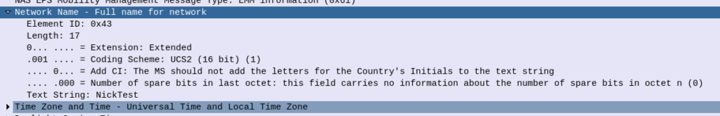
The major problem here is that there still won’t be an easy way to identify the operator of a particular network; the SPN is local only to the SIM and the Network Name is only present in the NAS messaging on an attach, and only after authentication.
If you’ve got a problem network, there’s no easy way to identify who’s operating it.
But as eSIMs become more prevalent and BIP / RFM on SIMs will hopefully allow operators to shift PLMNs without too much headache.
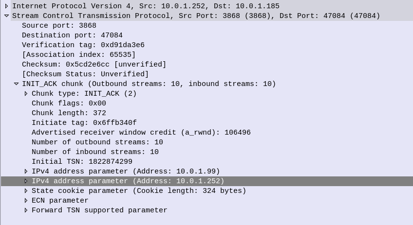
But if you really want to get the most bang for your buck, you’ll need to tune your SCTP parameters to match the network conditions.
While tuning the parameters per-association would be time consuming, most SCTP stacks allow you to set templates for SCTP parameters, for example you would have a different set of parameters for the SCTP stacks inside your network, compared to SCTP stacks for say a roaming scenario or across microwave links.
IETF kindly provides a table with their recommended starting values for SCTP parameter tuning:
But by adjusting the Max Retrans and Retransmission Timeout (RTO) values, we can detect failures on the network more quickly, and reduce the number of packets we’ll loose should we have a failure.
We begin with the engineered round-trip time (RTT) – that is made up of the time it takes to traverse the link, processing time for the remote SCTP stack and time for the response to traverse the link again. For the examples below we’ll take an imaginary engineered RTT of 200ms.
RTO.min is the minimum retransmission timeout. If this value is set too low then before the other side has had time to receive the request, process it and send a response, we’ve already retransmitted it.
This should be set to the round trip delay plus processing needed to send and acknowledge a packet plus some allowance for variability due to jitter; a value of 1.15 times the Engineered RTT is often chosen
So for us, 200 * 1.15 = 230ms RTO.min value.
RTO.max is the maximum amount of time we should wait before transmitting a request. Typically three times the Engineered RTT.
So for us, 200 * 3 = 600ms RTO.min value.
Path.Max.Retransmissions is the maximum number of retransmissions to be sent down a path before the path is considered to be failed. For example if we loose a transmission path on a multi-homed server, how many retransmissions along that path should we send until we consider it to be down?
Values set are dependant on if you’re multi-homing or not (you can be more picky if you are) and the level of acceptable packet loss in your transmission link.
Typical values are 4 Retransmissions (per destination address) for a Single-Homed association, and 2 Retransmissions (per destination address) for a Multi-Homed association.
Association.Max.Retransmissions is the maximum number of retransmissions for an association. If a transmission link in a multi-homed SCTP scenario were to go down, we would pass the Path.Max.Retransmissions value and the SCTP stack would stop sending traffic out that path, and try another, but what if the remote side is down? In that scenario all our paths would fail, so we need another counter – Path.Max.Retransmissions to count the total number of retransmissions to an association / destination. When the Association.Max.Retransmissions is reached the association is considered down.
In practice this value would be the number of paths, multiplied by the Path.Max.Retransmissions.
Network Slicing, is a new 5G Technology. Or is it?
Pre 3GPP Release 16 the capability to “Slice” a network already existed, in fact the functionality was introduced way back at the advent of GPRS, so what is so new about 5G’s Network Slicing?
Network Slice: A logical network that provides specific network capabilities and network characteristics
3GPP TS 123 501 / 3 Definitions and Abbreviations
Let’s look at the old and the new ways, of slicing up networks, pre release 16, on LTE, UMTS and GSM.
Old Ways: APN Separation
The APN or “Access Point Name” is used so the SGSN / MME knows which gateway to that subscriber’s traffic should be terminated on when setting up the session.
APN separation is used heavily by MVNOs where the MVNO operates their own P-GW / GGSN. This allows the MNVO can handle their own rating / billing / subscriber management when it comes to data. A network operator just needs to setup their SGSN / MME to point all requests to setup a bearer on the MVNO’s APN to the MNVO’s gateways, and presoto, it’s no longer their problem.
Later as customers wanted MPLS solutions extended over mobile (Typically LTE), MNOs were able to offer “private APNs”. An enterprise could be allocated an APN by the MNO that would ensure traffic on that APN would be routed into the enterprise’s MPLS VRF. The MNO handles the P-GW / GGSN side of things, adding the APN configuration onto it and ensuring the traffic on that APN is routed into the enterprise’s VRF.
Different QCI values can be assigned to each APN, to allow some to have higher priority than others, but by slicing at an APN level you lock all traffic to those QoS characteristics (Typically mobile devices only support one primary APN used for routing all traffic), and don’t have the flexibility to steer which networks which traffic from a subscriber goes to.
It’s not really practical for everyone to have their own APNs, due in part to the namespace limitations, the architecture of how this is usually done limits this, and the simple fact of everyone having to populate an APN unique to them would be a real headache.
5G replaces APNs with “DNNs” – Data Network Names, but the functionality is otherwise the same.
In Summary: APN separation slices all traffic from a subscriber using a special APN and provide a bearer with QoS/QCI values set for that APN, but does not allow granular slicing of individual traffic flows, it’s an all-or-nothing approach and all traffic in the APN is treated equally.
The old Ways: Dedicated Bearers
Dedicated bearers allow traffic matching a set rule to be provided a lower QCI value than the default bearer. This allows certain traffic to/from a UE to use GBR or Non-GBR bearers for traffic matching the rule.
The rule itself is known as a “TFT” (Traffic Flow Template) and is made up of a 5 value Tuple consisting of IP Source, IP Destination, Source Port, Destination Port & Protocol Number. Both the UE and core network need to be aware of these TFTs, so the traffic matching the TFT can get the QCI allocated to it.
This can be done a variety of different ways, in LTE this ranges from rules defined in a PCRF or an external interface like those of an IMS network using the Rx interface to request a dedicated bearers matching the specified TFTs via the PCRF.
Unlike with 5G network slicing, dedicated bearers still traverse the same network elements, the same MME, S-GW & P-GW is used for this traffic. This means you can’t “locally break out” certain traffic.
In Summary: Dedicated bearers allow you to treat certain traffic to/from subscribers with different precedence & priority, but the traffic still takes the same path to it’s ultimate destination.
This means one eNodeB can broadcast more than one PLMN and server more than one mobile network.
This slicing is very coarse – it allows two operators to share the same eNodeBs, but going beyond a handful of PLMNs on one eNB isn’t practical, and the PLMN space is quite limited (1000 PLMNs per country code max).
In Summary: MOCN allows slicing of the RAN on a very coarse level, to slice traffic from different operators/PLMNs sharing the same RAN.
Its use is focused on sharing RAN rather than slicing traffic for users.
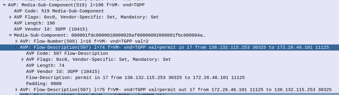
When it comes to setting up dedicated bearers, the Flow-Description AVP is perhaps the most important,
The specially encoded string (IPFilterRule) in the FlowDescription AVP is what our P-GW (Ok, our PCEF) uses to create Traffic Flow Templates to steer certain types of traffic down Dedicated Bearers.
So let’s take a look at how we can lovingly craft an artisanal Flow-Description.
The contents of the AVP are technically not a string, but a IPFilterRule.
IPFilterRules are actually defined in the Diameter Base Protocol (IETF RFC 6733), where we can learn the basics of encoding them,
Which are in turn based loosely off the ipfw utility in BSD.
They take the format:
action dir proto from src to dst
The action is fairly simple, for all our Dedicated Bearer needs, and the Flow-Description AVP, the action is going to be permit. We’re not blocking here.
The direction (dir) in our case is either in or out, from the perspective of the UE.
Next up is the protocol number (proto), as defined by IANA, but chances are you’ll be using 17 (UDP) or 6 (TCP) in most scenarios.
The from value is followed by an IP address with an optional subnet mask in CIDR format, for example from 10.45.0.0/16would match everything in the 10.45.0.0/16 network. Following from you can also specify the port you want the rule to apply to, or, a range of ports, For example to match a single port you could use 10.45.0.0/16 1234 to match anything on port 1234, but we can also specify ranges of ports like 10.45.0.0/16 0 – 4069 or even mix and match lists and single ports, like 10.45.0.0/16 5060, 1000-2000
Protip: using any is the same as 0.0.0.0/0
Like the from, the tois encoded in the same way, with either a single IP, or a subnet, and optional ports specified.
And that’s it!
Keep in mind that Flow-Descriptions are typically sent in pairs as a minimum, as you want to match the traffic into and out of the network (not just one way), but often there can be quite a few sent, in order to match all the possible traffic that needs to be matched that may be across multiple different subnets, etc.
There is an optional Options parameter that allows you to set things like to only apply the rule to open TCP sessions, fragmentation, etc, although I’ve not seen this implemented in the wild.
Example IP filter Rules
permit in 6 from 10.98.254.0/24 5061 to 10.98.0.0/24 5060
permit out 6 from 10.98.254.0/24 5060 to 10.98.0.0/24 5061

permit in 6 from any 80 to 172.16.1.1 80
permit out 6 from 172.16.1.1 80 to any 80

permit in 17 from 10.98.254.0/24 50000-60100 to 10.98.0.0/24 50000-60100
permit out 17 from 10.98.254.0/24 50000-60100 to 10.98.0.0/24 50000-60100

permit in 17 from 10.98.254.0/24 5061, 5064 to 10.98.0.0/24  5061, 5064
permit out 17 from 10.98.254.0/24 5061, 5064 to 10.98.0.0/24  5061, 5064

permit in 17 from 172.16.0.0/16 50000-60100, 5061, 5064 to 172.16.0.0/16  50000-60100, 5061, 5064
permit out 17 from 172.16.0.0/16 50000-60100, 5061, 5064 to 172.16.0.0/16  50000-60100, 5061, 5064
Since the beginning of time, SIP has used the 2xx responses to confirm all went OK.
If you thought sending an SMS in a VoLTE/IMS network would see a 2xx OK response and then that’s the end of it, you’d be wrong.
So let’s take a look into sending SMS over VoLTE/IMS networks!
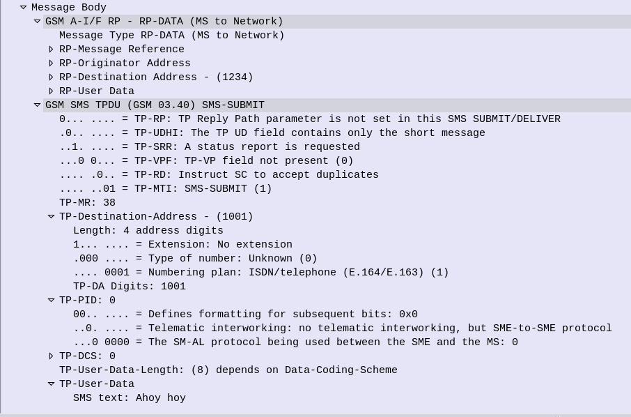
So our story starts with the Subscriber sending an SMS, which generate a SIP MESSAGE.
The Content-Type of this SIP MESSAGE is set to application/vnd.3gpp.sms rather than Text, and that’s because SMS over IMS uses the Short Message Transfer Protocol (SM-TP) inherited from GSM.
The Short Message Transfer Protocol (SM-TP) (Not related to Simple Message Transfer Protocol used in Email clients) is made up of Transfer Protocol Data Units (TPDU) that contain our message information, even though we have the Destination in our SIP headers, it’s again defined in the SM-TP body.
At first this may seem like a bit of duplication, but this allows older SMS Switching Centers (SMSc) to add support for IMS networks without any major changes, just what the SM-TP payload is wrapped up in changes.
SIP MESSAGE Request Body encoded in SM-TP
So back to our SIP MESSAGE request, typed out by the Subscriber, the UE sends this a SIP MESSAGE onto our IMS Network.
The IMS network follows it’s IFCs and routing rules, and makes it to the termination points for SMS traffic – the SMSc.
The SMSc sends back either a 200 OK or a 202 Accepted, and you’d think that’s the end of it, but no.
Our Subscriber still sees “Sending” on the screen, and the SMS is not shown as sent yet.
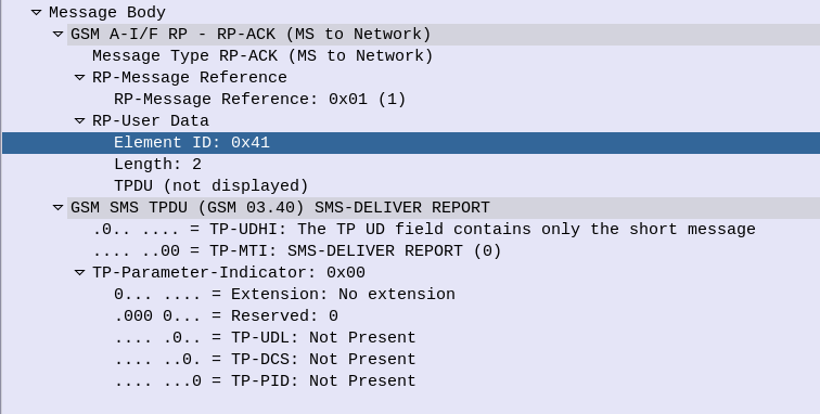
Instead, when the SMS has been delivered or buffered, relayed, etc, the SMSc generates a new SIP request, (as in new Call-ID / Dialog) with the request type MESSAGE, addressed to the Subscriber.
The payload of this request is another application/vnd.3gpp.sms encoded request body, again, containing SM-TP encoded data.
When the UE receives this, it will then consider the message delivered.
SM-TP encoded Delivery Report
Of course things change slightly when delivery reports are enabled, but that’s another story!
PDU Session Type: The type of PDU Session which can be IPv4, IPv6, IPv4v6, Ethernet or Unstructured
ETSI TS 123 501 – System Architecture for the 5G System
No longer are we limited to just IP transport, meaning at long last I can transport my Token Ring traffic over 5G, or in reality, customers can extend Layer 2 networks (Ethernet) over 3GPP technologies, without resorting to overlay networking, and much more importantly, fixed line networks, typically run at Layer 2, can leverage the 5G core architecture.
How does this work?
With TFTs and the N6 interfaces relying on the 5 value tuple with IPs/Ports/Protocol #s to make decisions, transporting Ethernet or Non-IP Data over 5G networks presents a problem.
But with fixed (aka Wireline) networks being able to leverage the 5G core (“Wireline Convergence”), we need a mechanism to handle Ethernet.
For starters in the PDU Session Establishment Request the UE indicates which PDN types, historically this was IPv4/6, but now if supported by the UE, Ethernet or Unstructured are available as PDU types.
We’ll focus on Ethernet as that’s the most defined so far,
Once an Ethernet PDU session has been setup, the N6 interface looks a bit different, for starters how does it know where, or how, to route unstructured traffic?
As far as 3GPP is concerned, that’s your problem:
Regardless of addressing scheme used from the UPF to the DN, the UPF shall be able to map the address used between the UPF and the DN to the PDU Session.
5.6.10.3 Support of Unstructured PDU Session type
In short, the UPF will need to be able to make the routing decisions to support this, and that’s up to the implementer of the UPF.
In the Ethernet scenario, the UPF would need to learn the MAC addresses behind the UE, handle ARP and use this to determine which traffic to send to which UE, encapsulate it into trusty old GTP, fill in the correct TEID and then send it to the gNodeB serving that user (if they are indeed on a RAN not a fixed network).
So where does this leave QoS? Without IPs to apply with TFTs and Packet Filter Sets to, how is this handled? In short, it’s not – Only the default QoS rule exist for a PDU Session of Type Unstructured. The QoS control for Unstructured PDUs is performed at the PDU Session level, meaning you can set the QFI when the PDU session is set up, but not based on traffic through that bearer.
Does this mean 5G RAN can transport Ethernet?
Well, it remains to be seen.
The specifications don’t cover if this is just for wireline scenarios or if it can be used on RAN.
The 5G PDU Creation signaling has a field to indicate if the traffic is Ethernet, but to work over a RAN we would need UE support as well as support on the Core.
And for E-UTRAN?
For the foreseeable future we’re going to be relying on LTE/E-UTRAN as well as 5G. So if you’re mobile with a non-IP PDU, and you enter an area only served by LTE, what happens?
PDU Session types “Ethernet” and “Unstructured” are transferred to EPC as “non-IP” PDN type (when supported by UE and network). … It is assumed that if a UE supports Ethernet PDU Session type and/or Unstructured PDU Session type in 5GS it will also support non-IP PDN type in EPS.
5.17.2 Interworking with EPC
If you were not aware of support in the EPC for Non-IP PDNs, I don’t blame you – So far support the CIoT EPS optimizations were initially for Non-IP PDN type has been for NB-IoT to supporting Non-IP Data Delivery (NIDD) for lightweight LwM2M traffic.
So why is this? Well, it may have to do with WO 2017/032399 Al which is a patent held by Ericsson, regarding “COMMUNICATION OF NON-IP DATA OVER PACKET DATA NETWORKS” which may be restricting wide scale deployment of this,
Give me a lever long enough and a fulcrum on which to place it, and I shall move the world.
For me, the equivalent would be:
Give me a packet capture of the problem occurring and a standards document against which to compare it, and I shall debug the networking world.
And if you’re like me, there’s a good chance when things are really not going your way, you roll up your sleeves, break out Wireshark and the standards docs and begin the painstaking process of trying to work out what’s not right.
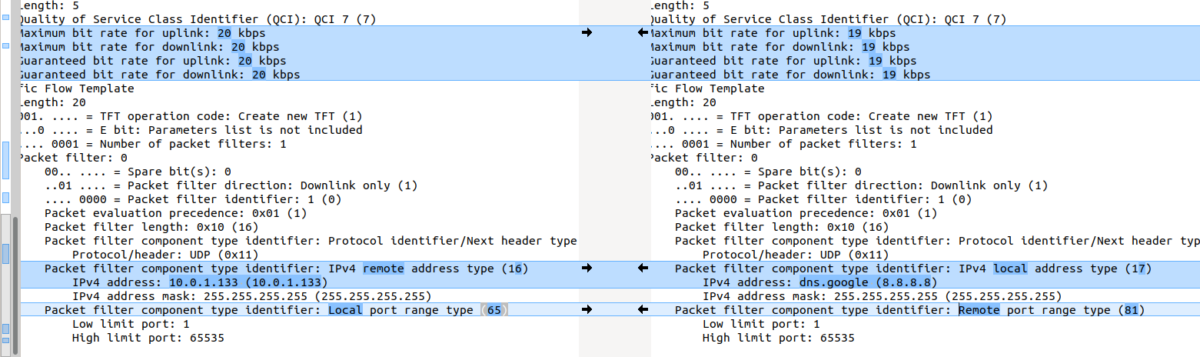
Today’s problem involved a side by side comparison between a pcap of a known good call, and one which is failing, so I just had to compare the two, which is slow and fairly error-prone,
So I started looking for something to diff PCAPs easily. The data I was working with was ASN.1 encoded so I couldn’t export as text like you can with HTTP or SIP based protocols and compare it that way.
In the end I stumbled across something even better to compare frames from packet captures side by side, with the decoding intact!
Turns out yo ucan copy the values including decoding from within Wireshark, which means you can then just paste the contents into a diff tool (I’m using the fabulous Meld on Linux, but any diff tool will do including diff itself) and off you go, side-by-side comparison.
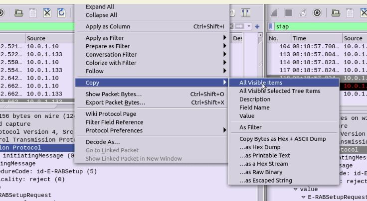
Select the first packet/frame you’re interested in (or even just the section), expand the subkeys, right click, copy “All Visible items”. This copy contains all the decoded data, not just the raw bytes, which is what makes it so great.
Next paste it into your diff tool of choice, repeat with the one to compare against, scroll past the data you know is going to be different (session IDs, IPs, etc) and ta-da, there’s the differences.
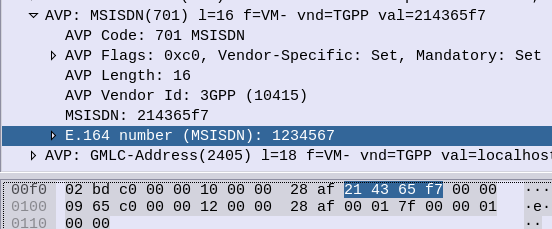
MSISDN AVP 700 / vendor ID 10415, used to advertise the subscriber’s MSISDN in signaling.
I formatted the data as an Octet String, with the MSISDN from the database and moved on my merry way.
Not so fast…
The MSISDN AVP is of type OctetString.
This AVP contains an MSISDN, in international number format as described in ITU-T Rec E.164 [8], encoded as a TBCD-string, i.e. digits from 0 through 9 are encoded 0000 to 1001;
1111 is used as a filler when there is an odd number of digits; bits 8 to 5 of octet n encode digit 2n; bits 4 to 1 of octet n encode digit 2(n-1)+1.
ETSI TS 129 329 / 6.3.2 MSISDN AVP
Come again?
In practice this means if you have an odd lengthed MSISDN value, we need to add some padding to round it out to an even-lengthed value.
This padding happens between the last and second last digit of the MSISDN (because if we added it at the start we’d break the Country Code, etc) and as MSISDNs are variable length subscriber numbers.
1111 in octet string is best known as the letter F,
Ok, admittedly I haven’t actually seen “When a Stranger Calls”, or the less popular sequel “When a stranger Redials” (Ok may have made the last one up).
But the premise (as I read Wikipedia) is that the babysitter gets the call on the landline, and the police trace the call as originating from the landline.
But you can’t phone yourself, that’s not how local loops work – When the murderer goes off hook it loops the circuit, which busys it. You could apply ring current to the line I guess externally but unless our murder has a Ring generator or has setup a PBX inside the house, the call probably isn’t coming from inside the house.
On Topic – The GMLC
The GMLC (Gateway Mobile Location Centre) is a central server that’s used to locate subscribers within the network on different RATs (GSM/UMTS/LTE/NR).
The GMLC typically has interfaces to each of the radio access technologies, there is a link between the GMLC and the CS network elements (used for GSM/UMTS) such as the HLR, MSC & SGSN via Lh & Lg interfaces, and a link to the PS network elements (LTE/NR) via Diameter based SLh and SLg interfaces with the MME and HSS.
The GMLC’s tentacles run out to each of these network elements so it can query them as to a subscriber’s location,
LTE Call Flow
To find a subscriber’s location in LTE Diameter based signaling is used, to query the MME which in turn queries, the eNodeB to find the location.
But which MME to query?
The SLh Diameter interface is used to query the HSS to find out which MME is serving a particular Subscriber (identified by IMSI or MSISDN).
The LCS-Routing-Info-Request is sent by the GMLC to the HSS with the subscriber identifier, and the LCS-Routing-Info-Response is returned by the HSS to the GMLC with the details of the MME serving the subscriber.
Now we’ve got the serving MME, we can use the SLgDiameter interface to query the MME to the location of that particular subscriber.
The MME can report locations to the GMLC periodically, or the GMLC can request the MME provide a location at that point. For the GMLC to request a subscriber’s current location a Provide-Location-Request is set by the GMLC to the MME with the subscriber’s IMSI, and the MME responds after querying the eNodeB and optionally the UE, with the location info in the Provide-Location-Response.
(I’m in the process of adding support for these interfaces to PyHSS and all going well will release some software shortly to act at a GMLC so people can use this.)
Finding the actual Location
There are a few different ways the actual location of the UE is determined,
At the most basic level, Cell Global Identity (CGI) gives the identity of the eNodeB serving a user. If you’ve got a 3 sector site each sector typically has its own Cell Global Identity, so you can determine to a certain extent, with the known radiation pattern, bearing and location of the sector, in which direction a subscriber is. This happens on the network side and doesn’t require any input from the UE. But if we query the UE’s signal strength, this can then be combined with existing RF models and the signal strength reported by the UE to further pinpoint the user with a bit more accuracy. (Uplink and downlink cell coverage based positioning methods) Barometric pressure and humidity can also be reported by the base station as these factors will impact resulting signal strengths.
Timing Advance (TA) and Time of Arrival (TOA) both rely on timing signals to/from a UE to determine it’s distance from the eNodeB. If the UE is only served by a single cell this gives you a distance from the cell and potentially an angle inside which the subscriber is. This becomes far more useful with 3 or more eNodeBs in working range of the UE, where you can “triangulate” the UE’s location. This part happens on the network side with no interaction with the UE. If the UE supports it, EUTRAN can uses Enhanced Observed Time Difference (E-OTD) positioning method, which does TOD calcuation does this in conjunction with the UE.
GPS Assisted (A-GPS) positioning gives good accuracy but requires the devices to get it’s current location using the GPS, which isn’t part of the baseband typically, so isn’t commonly implimented.
Uplink Time Difference of Arrival (UTDOA) can also be used, which is done by the network.
So why do we need to get Subscriber Locations?
The first (and most noble) use case that springs to mind is finding the location of a subscriber making a call to emergency services. Often upon calling an emergency services number the GMLC is triggered to get the subscriber’s location in case the call is cut off, battery dies, etc.
But GMLCs can also be used for lots of other purposes, marketing purposes (track a user’s location and send targeted ads), surveillance (track movements of people) and network analytics (look at subscriber movement / behavior in a specific area for capacity planning).
Different countries have different laws regulating access to the subscriber location functions.
Hack to disable Location Reporting on Mobile Networks
If you’re wondering how you can disable this functionality, you can try the below hack to ensure that your phone does not report your location.
Press the power button on your phone
Turn it off
In reality, no magic super stealth SIM cards, special phones or fancy firmware will prevent the GMLC from finding your location. So far none of the “privacy” products I’ve looked at have actually done anything special at the Baseband level. Most are just snakeoil.
For as long as your device is connected to the network, the passive ways of determining location, such as Uplink Time Difference of Arrival (UTDOA) and the CGI are going to report your location.
Australia is a strange country; As a kid I was scared of dogs, and in response, our family got a dog.
This year started off with adventures working with ASN.1 encoded data, and after a week of banging my head against the table, I was scared of ASN.1 encoding.
But now I love dogs, and slowly, I’m learning to embrace ASN.1 encoding.
What is ASN.1?
ASN.1 is an encoding scheme.
The best analogy I can give is to image a sheet of paper with a form on it, the form has fields for all the different bits of data it needs,
Each of the fields on the form has a data type, and the box is sized to restrict input, and some fields are mandatory.
Now imagine you take this form and cut a hole where each of the text boxes would be.
We’ve made a key that can be laid on top of a blank sheet of paper, then we can fill the details through the key onto the blank paper and reuse the key over and over again to fill the data out many times.
When we remove the key off the top of our paper, and what we have left on the paper below is the data from the form. Without the key on top this data doesn’t make much sense, but we can always add the key back and presto it’s back to making sense.
While this may seem kind of pointless let’s look at the advantages of this method;
The data is validated by the key – People can’t put a name wherever, and country code anywhere, it’s got to be structured as per our requirements. And if we tried to enter a birthday through the key form onto the paper below, we couldn’t.
The data is as small as can be – Without all the metadata on the key above, such as the name of the field, the paper below contains only the pertinent information, and if a field is left blank it doesn’t take up any space at all on the paper.
It’s these two things, rigidly defined data structures (no room for errors or misinterpretation) and the minimal size on the wire (saves bandwidth), that led to 3GPP selecting ASN.1 encoding for many of it’s protocols, such as S1, NAS, SBc, X2, etc.
It’s also these two things that make ASN.1 kind of a jerk; If the data structure you’re feeding into your ASN.1 compiler does not match it will flat-out refuse to compile, and there’s no way to make sense of the data in its raw form.
But working with a super simple ASN.1 definition you’ve created is one thing, using the 3GPP defined ASN.1 definitions is another,
With the aid of the fantastic PyCrate library, which is where the real magic happens, and this was the nut I cracked this week, compiling a 3GPP ASN.1 definition and communicating a standards-based protocol with it.
One of the key advantages of SCTP over TCP is the support for Multihoming,
From an application perspective, this enables one “socket”, to be shared across multiple IP Addresses, allowing multiple IP paths and physical NICs.
Through multihoming we can protect against failures in IP Routing and physical links, from a transport layer protocol.
So let’s take a look at how this actually works,
For starters there’s a few ways multihoming can be implemented, ideally we have multiple IPs on both ends (“client” and “server”), but this isn’t always achievable, so SCTP supports partial multi-homing, where for example the client has only one IP but can contact the server on multiple IP Addresses, and visa-versa.
The below image (Courtesy of Wikimedia) shows the ideal scenario, where both the client and the server have multiple IPs they can be reached on.
This would mean a failure of any one of the IP Addresses or the routing between them, would see the other secondary IP Addresses used for Transport, and the application not even necessarily aware of the interruption to the primary IP Path.
The Process
For starters, our SCTP Client/Server will each need to be aware of the IPs that can be used,
This is advertised in the INIT message, sent by the “client” to a “server” when the SCTP session is established.
SCTP INIT sent by the client at 10.0.1.185, but advertising two IPs
In the above screenshot we can see the two IPs for SCTP to use, the primary IP is the first one (10.0.1.185) and also the from IP, and there is just one additional IP (10.0.1.187) although there could be more.
In a production environment you’d want to ensure each of your IPs is in a different subnet, with different paths, hardware and routes.
So the INIT is then responded to by the client with an INIT_ACK, and this time the server advertises it’s IP addresses, the primary IP is the From IP address (10.0.1.252) and there is just one additional IP of 10.0.1.99,
SCTP INIT ACK showing Server’s Multi-homed IP Options
Next up we have the cookie exchange, which is used to protect against synchronization attacks, and then our SCTP session is up.
So what happens at this point? How do we know if a path is up and working?
Well the answer is heartbeat messages,
Sent from each of the IPs on the client to each of the IPs on the server, to make sure that there’s a path from every IP, to every other IP.
SCTP Heartbeats from each local IP to each remote IP
This means the SCTP stacks knows if a path fails, for example if the route to IP 10.0.1.252 on the server were to fail, the SCTP stack knows it has another option, 10.0.1.99, which it’s been monitoring.
So that’s multi-homed SCTP in action – While a lot of work has historically been done with LACP for aggregating multiple NICs together, and VRRP for ensuring a host is alive, SCTP handles this in a clean and efficient way.
I’ve attached a PCAP showing multi-homing on a Diameter S6a (HSS) interface between an MME and a HSS.
So dedicated appliances are dead and all our network functions are VMs or Containers, but there’s a performance hit when going virtual as the L2 processing has to be handled by the Hypervisor before being passed onto the relevant VM / Container.
If we have a 10Gb NIC in our server, we want to achieve a 10Gbps “Line Speed” on the Network Element / VNF we’re running on.
When we talked about appliances if you purchased an P-GW with 10Gbps NIC, it was a given you could get 10Gbps through it (without DPI, etc), but when we talk about virtualized network functions / network elements there’s a very real chance you won’t achieve the “line speed” of your interfaces without some help.
When you’ve got a Network Element like a S-GW, P-GW or UPF, you want to forward packets as quickly as possible – bottlenecks here would impact the user’s achievable speeds on the network.
To speed things up there are two technologies, that if supported by your software stack and hardware, allows you to significantly increase throughput on network interfaces, DPDK & SR-IOV.
DPDK – Data Plane Development Kit
Usually *Nix OSs handle packet processing on the Kernel level. As I type this the packets being sent to this WordPress server by Firefox are being handled by the Linux 5.8.0-36-generic kernel running on my machine.
The problem is the kernel has other things to do (interrupts), meaning increased delay in processing (due to waiting for processing capability) and decreased capacity.
DPDK shunts this processing to the “user space” meaning your application (the actual magic of the VNF / Network Element) controls it.
To go back to me writing this – If Firefox and my laptop supported DPDK, then the packets wouldn’t traverse the Linux kernel at all, and Firefox would be talking directly to my NIC. (Obviously this isn’t the case…)
So DPDK increases network performance by shifting the processing of packets to the application, bypassing the kernel altogether. You are still limited by the CPU and Memory available, but with enough of each you should reach very near to line speed.
SR-IOV – Single Root Input Output Virtualization
Going back to the me writing this analogy I’m running Linux on my laptop, but let’s imagine I’m running a VM running Firefox under Linux to write this.
If that’s the case then we have an even more convolted packet processing chain!
I type the post into Firefox which sends the packets to the Linux kernel, which waits to be scheduled resources by the hypervisor, which then process the packets in the hypervisor kernel before finally making it onto the NIC.
We could add DPDK which skips some of these steps, but we’d still have the bottleneck of the hypervisor.
With PCIe passthrough we could pass the NIC directly to the VM running the Firefox browser window I’m typing this, but then we have a problem, no other VMs can access these resources.
SR-IOV provides an interface to passthrough PCIe to VMs by slicing the PCIe interface up and then passing it through.
My VM would be able to access the PCIe side of the NIC, but so would other VMs.
So that’s the short of it, SR-IOR and DPDK enable better packet forwarding speeds on VNFs.