While we’ve already covered the inputs required by the authentication elements of the core network (The HSS in LTE/4G, the AuC in UMTS/3G and the AUSF in 5G) to generate an output, it’s worth noting that the Confidentiality Algorithms used in the process determines the output.
This means the Authentication Vector (Also known as an F1 and F1*) generated for a subscriber using Milenage Confidentiality Algorithms will generate a different output to that of Confidentiality Algorithms XOR or Comp128.
To put it another way – given the same input of K key, OPc Key (or OP key), SQN & RAND (Random) a run with Milenage (F1 and F1* algorithm) would yield totally different result (AUTN & XRES) to the same inputs run with a simple XOR.
Technically, as operators control the network element that generates the challenges, and the USIM that responds to them, it is an option for an operator to implement their own Confidentiality Algorithms (Beyond just Milenage or XOR) so long as it produced the same number of outputs. But rolling your own cryptographic anything is almost always a terrible idea.
So what are the differences between the Confidentiality Algorithms and which one to use? Spoiler alert, the answer is Milenage.
Milenage
Milenage is based on AES (Originally called Rijndael) and is (compared to a lot of other crypto implimentations) fairly easy to understand,
AES is very well studied and understood and unlike Comp128 variants, is open for anyone to study/analyse/break, although AES is not without shortcomings, it’s problems are at this stage, fairly well understood and mitigated.
There are a few clean open source examples of Milenage implementations, such as this C example from FreeBSD.
XOR
It took me a while to find the specifications for the XOR algorithm – it turns out XOR is available as an alternate to Milenage available on some SIM cards for testing only, and the mechanism for XOR Confidentiality Algorithm is only employed in testing scenarios, not designed for production.
Instead of using AES under the hood like Milenage, it’s just plan old XOR of the keys.
Comp128 was originally a closed source algorithm, with the maths behind it not publicly available to scrutinise. It is used in GSM A3 and A5 functions, akin to the F1 and F1* in later releases.
Due to its secretive nature it wasn’t able to be studied or analysed prior to deployment, with the idea that if you never said how your crypto worked no one would be able to break it. Spoiler alert; public weaknesses became exposed as far back as 1998, which led to Toll Fraud, SIM cloning and eventually the development of two additional variants, with the original Comp128 renamed Comp128-1, and Comp128-2 (stronger algorithm than the original addressing a few of its flaws) and Comp128-3 (Same as Comp128-2 but with a 64 bit long key generated).
Recently I’ve been wrapping my head around Cell Broadcast in LTE, and thought I’d share my notes on 3GPP TS 38.413.
The interface between the MME and the Cell Broadcast Center (CBC) is the SBc interface, which as two types of “Elementary Procedures”:
Class 1 Procedures are of the request – response nature (Request followed by a Success or Failure response)
Class 2 Procedures do not get a response, and are informational one-way. (Acked by SCTP but not an additional SBc message).
SCTP is used as the transport layer, with the CBC establishing a point to point connection to the MME over SCTP (Unicast only) on port 29168 with SCTP Payload Protocol Identifier 24.
The SCTP associations between the MME and the CBC should normally remain up – meaning the SCTP association / transport connection is up all the time, and not just brought up when needed.
Elementary Procedures
Write-Replace Warning (Class 1 Procedure)
The purpose of Write-Replace Warning procedure is to start, overwrite the broadcasting of warning message, as defined in 3GPP TS 23.041 [14].
Write-Replace Warning procedure, initiated by WRITE-REPLACE WARNING REQUEST sent by the CBC to the MMEs contains the emergency message to be broadcast and the parameters such as TAC to broadcast to, severity level, etc.
A WRITE-REPLACE WARNING RESPONSE is sent back by the MME to the MME, if successful, along with information as to where it was sent out. CBC messages are unacknowledged by UEs, meaning it’s not possible to confirm if a UE has actually received the message.
The request includes the message identifier and serial number, list of TAIs, repetition period, number of broadcasts requested, warning type, and of course, the warning message contents.
Stop Warning Procedure (Class 1 Procedure)
Stop Warning Procedure, initiated by STOP WARNING REQUEST and answered with a STOP WARNING RESPONSE, requests the MME inform the eNodeBs to stop broadcasting the CBC in their SIBs.
Includes TAIs of cells this should apply to and the message identifier,
Error Indication (Class 2)
The ERROR INDICATION is used to indicate an error (duh). Contains a Cause and Criticality IEs and can be sent by the MME or CBC.
Write Replace Warning (Class 2)
The WRITE REPLACE WARNING INDICATION is used to indicate warning scenarios for some instead of a WRITE-REPLACE WARNING RESPONSE,
PWS Restart (Class 2)
The PWS RESTART INDICATION is used to list the eNodeBs / cells, that have become available or have restarted, since the CBC message and have no warning message data – for example eNodeBs that have just come back online during the period when all the other cells are sending Cell Broadcast messages.
Returns a the Restarted-Cell-List IE, containing the Global eNB ID IE and List of TAI, of the restarted / reconnected cells.
PWS Failure Indication (Class 2)
The PWS FAILURE INDICATION is essentially the reverse of PWS RESTART INDICATION, indicating which eNodeBs are no longer available. These cells may continue to send Cell Broadcast messages as the MME has essentially not been able to tell it to stop.
Contains a list of Failed cells (eNodeBs) with the Global-eNodeB-ID of each.
Mobile networks are designed to be redundant and resilient, with N+1 for everything.
Every network element connects to multiple other network elements.
The idea being the network is architected so a failure of any one network element will not impact service.
To take an LTE/EPC example, your eNodeBs connect to multiple MMEs, which in turn connect to multiple HSSs, multiple S-GWs, multiple EIRs, etc. The problem is when each eNodeB connects to 3 MMEs, and you want to add a 4th MME, you have to go and reconfigure all the eNodeBs to point to the new MME, and all the HSSs to accept that MME as a new Diameter Peer, for example.
The more redundant you make the network, the harder it becomes to change.
This led to development of network elements like Diameter Routing Agents (DRAs) and DNS SRV for service discovery, but ultimately adding and removing network elements in previous generations of mobile core, involved changing a lot of config on a lot of different boxes.
The Solution
The NRF – Network Repository Function serves as a central repository for Network Functions (NFs) on the network.
In practice this means when you bring a new Network Function / Network Element online, you only need to point it at the NRF, which will tell it about other Network Functions on the network, register the new Network Function and let every other interested Network Function know about the new guy.
Take for example adding a new AMF to the network, after bringing it online the only bit of information the AMF really needs to start placing itself in the network, is the details of the NRF, so it can find everything it needs to know.
Our new AMF will register itself to the NRF, advertising what Network Functions it can offer (ie AMF service), and it’ll in turn be able to learn about what Network Functions it can consume – for example our AMF would need to know about the UDMs it can query data from.
It is one of the really cool design patterns usually seen in modern software, that 3GPP have adopted as part of the 5GC.
In Practice
Let’s go into a bit more detail and look at how it looks.
The NRF uses HTTP and JSON to communicate (anything not using ASN.1 is a winner), and looks familiar to anyone used to dealing with RESTful APIs.
Let’s take a look at how an AMF looks when registering to a NRF,
NF Register – Providing the NRF a profile for each NF
In order for the NRF to function it has to know about the presence of all the Network Functions on the network, and what they support. So when a new Network Function comes online, it’s got to introduce itself to the NRF.
It does this by providing a “Profile” containing information about the Network Functions it supports, IP Addresses, versions, etc.
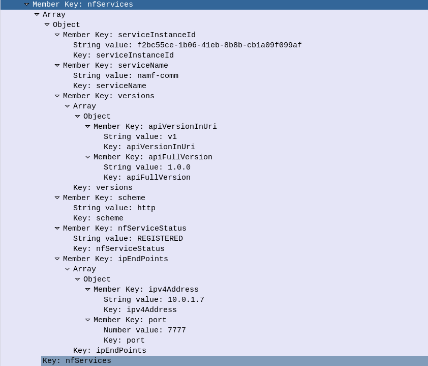
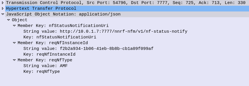
Going back to our AMF example, the AMF sends a HTTP PUT request to our NRF, with a JSON payload describing the functions and capabilities of the AMF, so other Network Functions will be able to find it.
Let’s take a look at what’s in the JSON payload used for the NF Profile.
Each Network Function is identified by a UUID – nfInstanceId, in this example it’s value is “f2b2a934-1b06-41eb-8b8b-cb1a09f099af”
The nfType (Network Function type) is an AMF, and it’s IP Address is 10.0.1.7
The heartBeatTimer sets how often the network function (in this case AMF) sends messages to the NRF to indicate it’s still alive. This prevents a device registering to an NRF and then going offline, and the NRF not knowing.
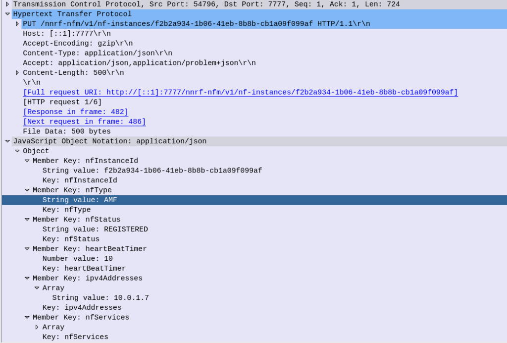
The nfServices key contains an array of services and details of those services, in the below example the key feature is the serviceName which is namf-comm which means the Namf_Communication Service offered by the AMF.
The NRF files this info away for anyone who requests it (more on that later) and in response to this our NRF will indicate (hopefully) that it’s successfully created the entry in its internal database of Network Functions for our AMF, resulting in a HTTP 201 “Created” response back from the NRF to the AMF.
NRF StatusSubscribe – Subscribe & Notify
Simply telling the NRF about the presence of NFs is one thing, but it’s not much use if nothing is done with that data.
A Network Function can subscribe to the NRF to get updates when certain types of NFs enter/leave the network.
Subscribing is done by sending a HTTP POST with a JSON payload indicating which NFs we’re interested in.
Contents of a Subscription message to be notified of all AMFs joining the network
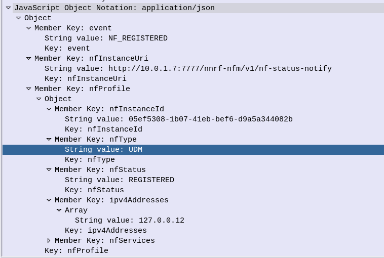
Whenever a Network Function registers on the NRF that related to the type that has been subscribed to, a HTTP POST is sent to each subscriber to let them know.
For example when a UDM registers to the network, our AMF gets a Notification with information about the UDM that’s just joined.
NRF Update – Updating NRF Profiles & Heartbeat
If our AMF wants to update its profile in the NRF – for example a new IP is added to our AMF, a HTTP PATCH request is sent with a JSON payload with the updated details, to the NRF.
The same mechanism is used as the Heartbeat / keepalive mechanism, to indicate the NRF is still there and working.
Summary
The NRF acts as a central repository used for discovery of neighboring network functions.
As the standardisation for 5G-SA has been completed and the first roll outs are happening, I thought I’d cover the basic architecture of the 5G Core Network, for people with a background in EPC/SAE networks for 4G/LTE, covering the key differences, what’s the same and what’s new.
The AMF – Authentication & Mobility Function, serves much the same role as the MME in LTE/EPC/SAE networks.
Like the MME, the AMF only handles Control Plane traffic, and serves as the gatekeeper to the services on the network, connecting the RAN to the core, authenticating subscribers and starting data / PDN connections for the UEs.
While the MME connects to eNodeBs for RAN connectivity, the AMF connects to gNodeBs for RAN.
The Authentication Functions
In EPC the HSS had two functions; it was a database of all subscribers’ profile information and also the authentication centre for generating authentication vectors.
5GC splits this back into two network elements (Akin to the AuC and HLR in 2G/3G).
The UDM (Unified Data Management) provides the AMF with the subscriber profile information (allowed / barred services / networks, etc),
The AUSF (Authentication Server Function) provides the AMF with the authentication vectors for authenticating subscribers.
Like in UMTS/LTE USIMs are used to authenticate subscribers when connecting to the network, again using AKA (Authentication and Key Agreement) for mutual subscriber & network authentication.
Other authentication methods may be implemented, R16 defines 3 suporrted methods, 5G-AKA, EAP-AKA’, and EAP-TLS.
This opens the door for the 5GC to be used for non-mobile usage. There has been early talk of using the 5G architecture for fixed line connectivity as well as mobile, hence supporting a variety of authentication methods beyond classic AKA & USIMs. (For more info about Non-3GPP Access interworking look into the N3IWF)
The Mobility Functions
When a user connects to the network the AMF selects a SMF (Session Management Function) akin to a P-GW-C in EPC CUPS architecture and requests the SMF setup a connection for the UE.
This is similar to the S11 interface in EPC, however there is no S-GW used in 5GC, so would be more like if S11 were instead sent to the P-GW-C.
The SMF selects a UPF (Akin to the P-GW-C selecting a P-GW-U in EPC), which will handle this user’s traffic, as the UPF bridges external data networks (DNs) to the gNodeB serving the UE.
Moving between cells / gNodeBs is handled in much the same way as done previously, with the path the UPF sends traffic to (N3 interface) updated to point to the IP of the new gNodeB.
When a UE attempts to connect to the network their signalling traffic (Using the N1 reference point between the UE and the AMF), is sent to the AMF.
an authentication challenge is issued as in previous generations.
Upon successful authentication the AMF signals the SMF to setup a session for the UE. The SMF selects a UPF to handle the user plane forwarding to the gNodeB serving the UE.
Key Differences
Functions handled by the MME in EPC now handled by AMF in 5GC
Functions of HSS now in two Network Functions – The UDM (Unified Data Management) and AUSF (Authentication Server Function)
Setting up data connections “flatter” (more info on the User Plane differences can be found here)
Non 3GPP access (Potentially used for fixed-line / non mobile networks)
As the standardisation for 5G-SA has been completed and the first roll outs are happening, I thought I’d cover the basic architecture of the 5G Core Network, for people with a background in EPC/SAE networks for 4G/LTE, covering the key differences, what’s the same and what’s new.
The idea behind this, is that by removing the S-GW removes extra hops / latency in the network, and allows users to be connected to the best UPF for their needs, typically one located close to the user.
However, there are often scenarios where an intermediate function is required – for example wanting to anchor a session to keep an IP Address allocated to one UPF associated with a user, while they move around the network. In this scenario a UPF can act as an “Session Anchor” (Akin to a P-GW), and pass through “Intermediate UPFs” (Like S-GWs).
Unlike the EPCs architecture, there is no limit to how many I-UPFs can be chained together between the Session Anchoring UPF and the gNB, and this chaining of UPFs allows for some funky routing options.
The UPF is dumb by design. The primary purpose is just to encapsulate traffic destined from external networks to subscribers into GTP-U packets and forward them onto the gNodeB serving that subscriber, and the same in reverse. Do one thing and do it well.
SMF – Session Management Function
So with dumb UPFs we need something smarter to tell them what to do.
Control of the UPFs is handled by the SMF – Session Management Function, which signals using PFCP down to the UPFs to tell them what to do in terms of setting up connections.
This means the interface between the SMF and UPF (the N4 interface) is more or less the same as the interface between a P-GW-C and a P-GW-U seen in CUPS.
When a subscriber connects to the network and has been authenticated, the AMF (For more info on the AMF see the sister post to this topic covering Control Plane traffic) requests the SMF to setup a connection for the subscriber.
Interworking with EPC
For deployments with an EPC and 5GC interworking between the two is of course required.
The P-GW-C and P-GW-U communications using PFCP are essentially the same as the N4 interface (between the SMF and the UPF) so the P-GW-U is able to act as a UPF.
This means handovers between the two RATs / Cores is seamless as when moving from an LTE RAT and EPC to a 5G RAT and 5G Core, the same UPF/P-GW-U is used, and only the Control Plane signalling around it changes.
When moving from LTE to 5G RAT, the P-GW-C is replaced by the SMF, When moving from 5G RAT to LTE, the SMF is replaced by the P-GW-C. In both scenarios user plane traffic takes the same exit point to external Data Networks (SGi interface in EPC / N6 interface in 5GC).
Interfaces / Reference Points
N3 Interface
N3 interface connects the gNodeB user plane to the UPF, to transport GTP-U packets.
This is a User Plane interface, and only transports user plane traffic.
This is akin to the S1-UP interface in EPC.
N4 Interface
N4 interface connects the Session Management Function (SMF) control plane to the UPF, to setup, modify and delete UPF sessions.
It is a control plane interface, and does not transport User Plane traffic.
This interface relies on PFCP – Packet Forwarding Control Protocol.
This is akin to the SxB interface in EPC with CUPS.
N6 Interface
N6 interface connects the UPF to External Data Networks (DNs), taking packets destined for Subscribers and encapsulating them into GTP-U packets.
This is a User Plane interface, and only transports user plane traffic.
This is akin to the SGi interface in EPC.
N9 Interface
When Session Anchoring is used, and Intermediate-UPFs are used, the connection between these UPFs uses the N9 interface.
This is only used in certain scenarios – the preference is generally to avoid unnecessary hops, so Intermediate-UPF usage is to be avoided where possible.
As this is a User Plane interface, it only transports user plane traffic.
When used this would be akin to the S5 interface in EPC.
N11 Interface
SMFs need to be told when to setup / tear down connections, this information comes from the AMF via the N11 interface.
As this is a Control Plane interface, it only transports control plane traffic.
This is similar to the S11 interface between the MME and the S-GW in EPC, however it would be more like the S11 if the S11 terminated on the P-GW.
Most people think of SIP when it comes to FreeSWITCH, Asterisk and Kamailio, but all three support WebRTC.
FreeSWITCH makes WebRTC fairly easy to use and treats it much the same way as any SIP endpoint, in terms of registration and diaplan.
Setting up the SIP Profile
On the SIP profile we’ll need to activate WebRTC you’ll need to ensure a few lines of config are present:
    <!-- for sip over secure websocket support -->
    <!-- You need wss.pem in $${certs_dir} for wss or one will be created for you -->
    <param name="wss-binding" value=":7443"/>
Next you’ll need to restart FreeSWITCH and a self-signed certificate should get loaded,
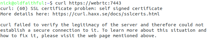
Once you’ve restarted FreeSWITCH will fail to detect any WebSocket certificate and generate a self signed certificate for you. This means that you can verify FreeSWITCH is listening as expected using Curl:
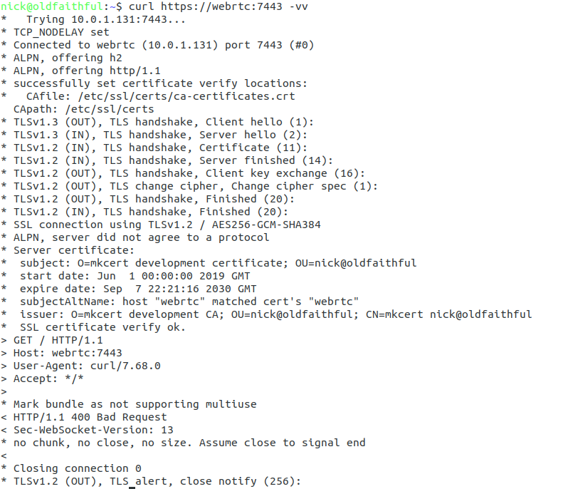
curl https://yourhostname:7443 -vvv
You should see an error regarding the connection failing due to an invalid certificate, if so, great! Let’s put in a valid certificate.
If not double check the firewall on your server allow traffic to port TCP 7443,
Loading your TLS Certificate
WebRTC & websocket are recent standards – this means a valid TLS certificate is mandatory. So to get this to work you’ll need a valid SSL certificate.
When we restarted FreeSWITCH after adding the wss-binding config a certificate was automatically generated in the $${certs_dir} of FreeSWITCH,
You can verify where the certs_dir is by echoing out the variable in FreeSWITCH:
fs_cli -x 'eval $${certs_dir}'
Unless you’ve changed it you’ll probably find your certs in /etc/freeswitch/tls/
The certificate and private key are stored in a single file, with the Certificate and the Private Key appended to the end,
In my case the certificate is called “webrtc.pem” and the private key file is “webrtc-key.pem”,
I’ll need to start by replacing the contents of the current certificate/ key file wss.pem with the certificate I’ve got webrtc.pem, and then appending the private key – webrtc-key.pem to the end of wss.pem,
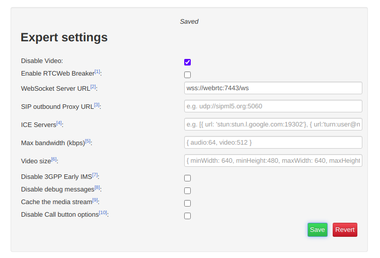
We’ll start by clicking the “Export Mode” button to set our wss:// URL;
Change the WebSocket Server URL to the URL of your FreeSWITCH instance (you must use a domain, not an IP Address)
If you’re running behind a NAT adding ICE servers is probably a good idea, although this will slow down connection times, you can use Google’s public STUN server by pasting in the below value:
[{ url: 'stun:stun.l.google.com:19302'}]
Finally we’ll save those settings and return back to the main tab,
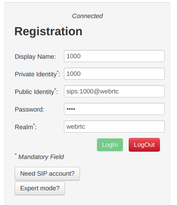
You’ll need to register with a username and password that’s valid on the FreeSWITCH box, in my case I’m using 1000 with the password 1000 (exists by default),
Replace webrtc with the domain name of your FreeSWITCH instance,
Finally you should be able to click Login and see Connected above,
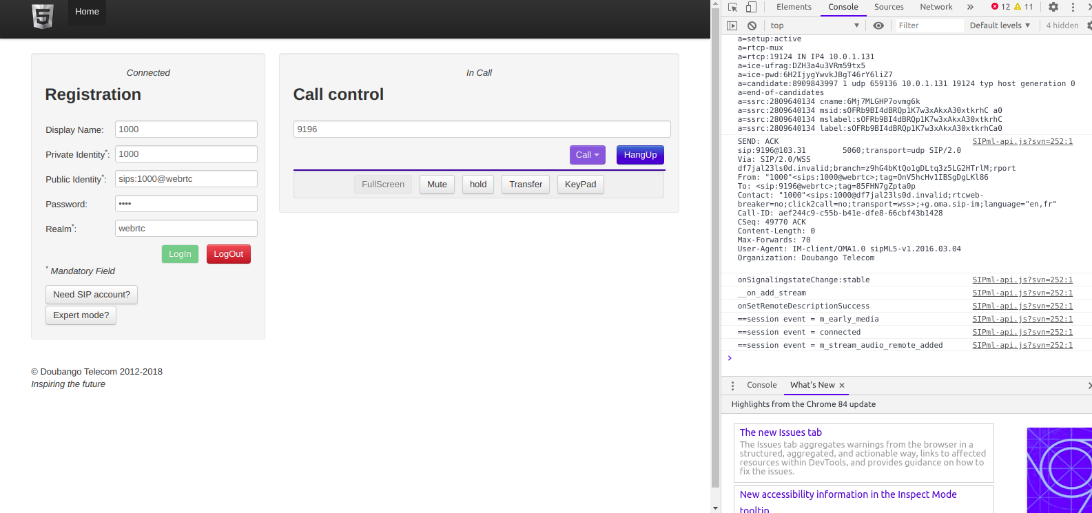
Then we can make calls to endpoints on FreeSWITCH using the dial box;
The Debug console in your browser will provide all the info you need to debug any issues, and you can trace WebSocket traffic using Sofia like any other SIP traffic.
Hopefully this was useful to you – I’ll cover more of WebRTC on Asterisk and also Kamailio in later posts!
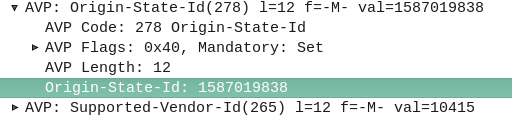
The Origin-State-Id AVP solves a kind of tricky problem – how do you know if a Diameter peer has restarted?
It seems like a simple problem until you think about it. One possible solution would be to add an AVP for “Recently Rebooted”, to be added on the first command queried of it from an endpoint, but what if there are multiple devices connecting to a Diameter endpoint?
The Origin-State AVP is a strikingly simple way to solve this problem. It’s a constantly incrementing counter that resets if the Diameter peer restarts.
If a client receives a Answer/Response where the Origin-State AVP is set to 10, and then the next request it’s set to 11, then the one after that is set to 12, 13, 14, etc, and then a request has the Origin-State AVP set to 5, the client can tell when it’s restarted by the fact 5 is lower than 14, the one before it.
It’s a constantly incrementing counter, that allows Diameter peers to detect if the endpoint has restarted.
Simple but effective.
You can find more about this in RFC3588 – the Diameter Base Protocol.
There’s a lot of layers of signalling in the LTE / EUTRAN attach procedure, but let’s take a look at the UE attach procedure from the Network Perspective.
We won’t touch on the air interface / Uu side of things, just the EPC side of the signaling.
To make life a bit easier I’ve put different signalling messages in different coloured headings:
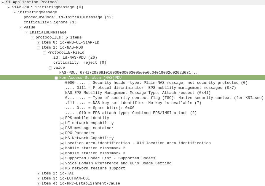
After a UE establishes a connection with a cell, the first step involved in the attach process is for the UE / subscriber to identify themselves and the network to authenticate them.
The TAI, EUTRAN-CGI and GUMME-ID sections all contain information about the serving network, such the tracking area code, cell global identifier and global MME ID to make up the GUTI.
The NAS part of this request contains key information about our UE and it’s capabilities, most importantly it includes the IMSI or TMSI of the subscriber, but also includes important information such as SRVCC support, different bands and RAN technologies it supports, codecs, but most importantly, the identity of the subscriber.
If this is a new subscriber to the network, the IMSI is sent as the subscriber identity, however wherever possible sending the IMSI is avoided, so if the subscriber has connected to the network recently, the M-TMSI is used instead of the IMSI, and the MME has a record of which M-TMSI to IMSI mapping it’s allocated.
Diameter: Authentication Information Request
MME to HSS
The MME does not have a subscriber database or information on the Crypto side of things, instead this functionality is offloaded to the HSS.
I’ve gone on and on about LTE UE/Subscriber authentication, so I won’t go into the details as to how this mechanism works, but the MME will send a Authentication-Information Request via Diameter to the HSS with the Username set to the Subscriber’s IMSI.
Diameter: Authentication Information Response
HSS to MME
Assuming the subscriber exists in the HSS, a Authentication-Information Answer will be sent back from the HSS via Diameter to the MME, containing the authentication vectors to send to the UE / subscriber.
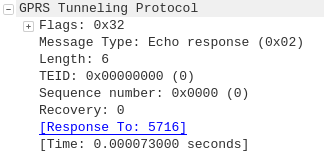
Now the MME has the Authentication vectors for that UE / Subscriber it sends back a DownlinkNASTransport, Authentication response, with the NAS section populated with the RAND and AUTN values generated by the HSS in the Authentication-Information Answer.
The Subscriber / UE’s USIM looks at the AUTN value and RAND to authenticate the network, and then calculates it’s response (RES) from the RAND value to provide a RES to send back to the network.
S1AP: UplinkNASTransport, Authentication response
eNB to MME
The subscriber authenticates the network based on the sent values, and if the USIM is happy that the network identity has been verified, it generates a RES (response) value which is sent in the UplinkNASTransport, Authentication response.
The MME compares the RES sent Subscriber / UE’s USIM against the one sent by the MME in the Authentication-Information Answer (the XRES – Expected RES).
If the two match then the subscriber is authenticated.
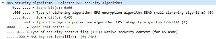
The DownlinkNASTransport, Security mode command is then sent by the MME to the UE to activate the ciphering and integrity protection required by the network, as set in the NAS Security Algorithms section;
The MME and the UE/Subscriber are able to derive the Ciphering Key (CK) and Integrity Key (IK) from the sent crypto variables earlier, and now both know them.
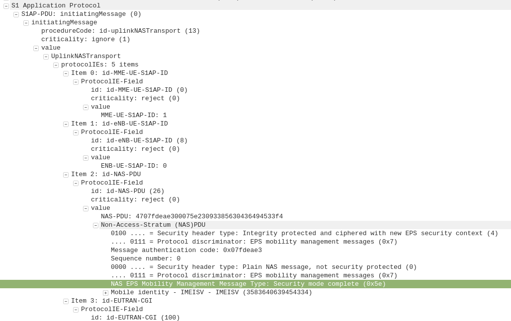
S1AP: UplinkNASTransport, Security mode complete
eNB to MME
After the UE / Subscriber has derived the Ciphering Key (CK) and Integrity Key (IK) from the sent crypto variables earlier, it can put them into place as required by the NAS Security algorithms sent in the Security mode command request.
It indicates this is completed by sending the UplinkNASTransport, Security mode complete.
At this stage the authentication of the subscriber is done, and a default bearer must be established.
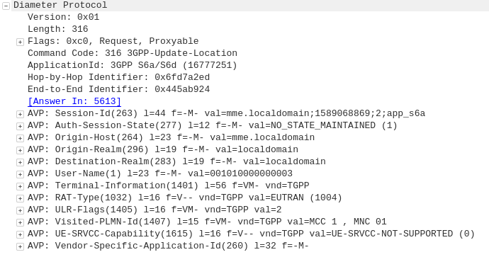
Diameter: Update Location Request
MME to HSS
Once the Security mode has been completed the MME signals to the HSS the Subscriber’s presence on the network and requests their Subscription-Data from the HSS.
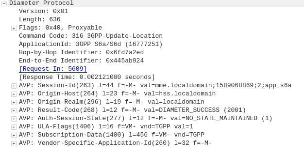
Diameter: Update Location Answer
HSS to MME
The ULA response contains the Subscription Data used to define the data service provided to the subscriber, including the AMBR (Aggregate Maximum Bit Rate), list of valid APNs and TAU Timer.
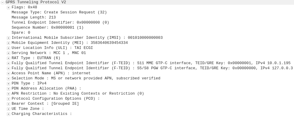
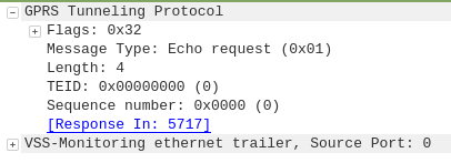
GTP-C: Create Session Request
MME to S-GW
The MME transfers the responsibility of setting up the data bearers to the S-GW in the form of the Create Session Request.
This includes the Tunnel Endpoint Identifier (TEID) to be assigned for this UE’s PDN.
The S-GW looks at the request and forwards it onto a P-GW for IP address assignment and access to the outside world.
GTP-C: Create Session Request
S-GW to P-GW
The S-GW sends a Create Session Request to the P-GW to setup a path to the outside world.
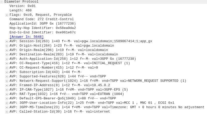
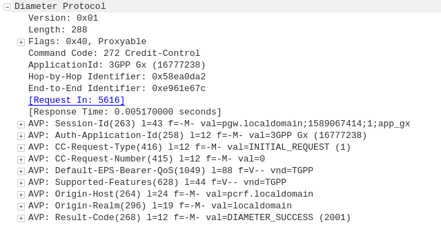
Diameter: Credit Control Request
P-GW to PCRF
To ensure the subscriber is in a state to establish a new PDN connection (not out of credit etc), a Credit Control Request is sent to the HSS.
Diameter: Credit Control Answer
PCRF to P-GW
Assuming the Subscriber has adequate credit for this, a Credit Control Answer is sent and the P-GW and continue the PDN setup for the subscriber.
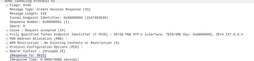
GTP-C: Create Session Response
P-GW to S-GW
The P-GW sends back a Create Session Response, containing the IP address allocated to this PDN (Framed-IP-Address).
GTP-C: Create Session Response
S-GW to MME
The S-GW slightly changes and then relays the Create Session Response back to the MME,
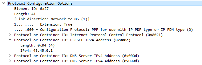
This message is sent to inform the eNB of the details of the PDN connection to be setup, ie AMBR, tracking area list, APN and Protocol Configuration Options,
This contains the Tunnel Endpoint Identifier (TEID) for this PDN to identify the GTP packets.
These posts focus on the use of Diameter and SIP in an IMS / VoLTE context, however these practices can be equally applied to other networks.
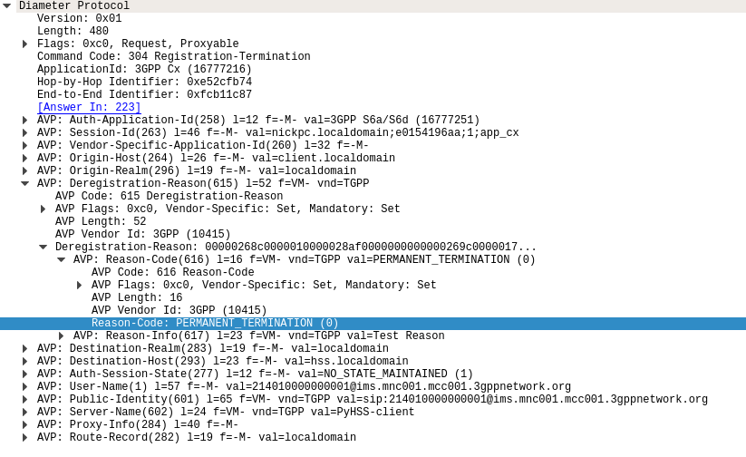
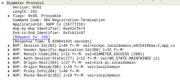
The Registration-Termination Request / Answer allow a Diameter Client (S-CSCF) to indicate to the HSS (Diameter Server) that it is no longer serving that user and the registration has been terminated.
Basics:
The RFC’s definition is actually pretty succinct as to the function of the Server-Assignment Request/Answer:
The Registration-Termination-Request is sent by a Diameter Multimedia server to a Diameter Multimedia client in order to request the de-registration of a user.
Reference: TS 29.229
The Registration-Termination-Request commands are sent by a S-CSCF to indicate to the Diameter server that it is no longer serving a specific subscriber, and therefore this subscriber is now unregistered.
There are a variety of reasons for this, such as PERMANENT_TERMINATION, NEW_SIP_SERVER_ASSIGNED and SIP_SERVER_CHANGE.
The Diameter Server (HSS) will typically send the Diameter Client (S-CSCF) a Registration-Termination-Answer in response to indicate it has updated it’s internal database and will no longer consider the user to be registered at that S-CSCF.
Packet Capture
I’ve included a packet capture of these Diameter Commands from my lab network which you can find below.
These posts focus on the use of Diameter and SIP in an IMS / VoLTE context, however these practices can be equally applied to other networks.
The Diameter User-Authorization-Request and User-Authorization-Answer commands are used as the first line of authorization of a user and to determine which Serving-CSCF to forward a request to.
Basics
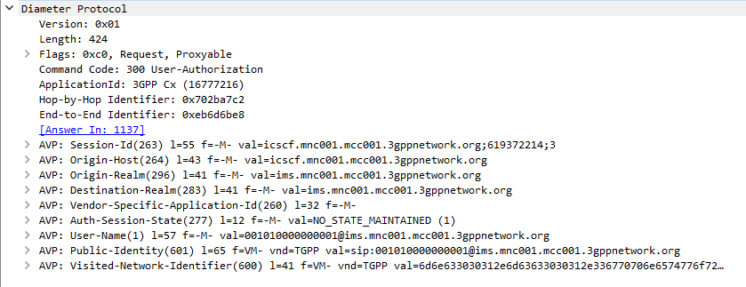
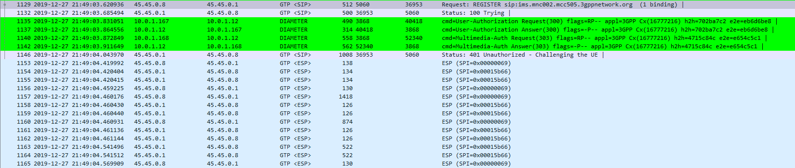
When a SIP Proxy (I-CSCF) receives an incoming SIP REGISTER request, it sends a User-Authorization-Request to a Diameter server to confirm if the user exists on the network, and which S-CSCF to forward the request to.
When the Diameter server receives the User-Authorization-Request it looks at the User-Name (1) AVP to determine if the Domain / Realm is served by the Diameter server and the User specified exists.
Assuming the user & domain are valid, the Diameter server sends back a User-Authorization-Answer, containing a Server-Capabilities (603) AVP with the Server-Name of the S-CSCF the user will be served by.
I always find looking at the packets puts everything in context, so here’s a packet capture of both the User-Authorization-Request and the User-Authorization-Answer.
Wireshark display of User-Authorization-Request packet
Wireshark display of User-Authorization-Answer packet
First Registration
If this is the first time this Username / Domain combination (Referred to in the RFC as an AOR – Address of Record) is seen by the Diameter server in the User-Authorization-Request it will allocate a S-CSCF address for the subscriber to use from it’s pool / internal logic.
The Diameter server will store the S-CSCF it allocated to that Username / Domain combination (AoR) for subsequent requests to ensure they’re routed to the same S-CSCF.
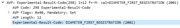
The Diameter server indicates this is the first time it’s seen it by adding the DIAMETER_FIRST_REGISTRATION (2001) AVP to the User-Authorization-Answer.
Subsequent Registration
If the Diameter server receives another User-Authorization-Request for the same Username / Domain (AoR) it has served before, the Diameter server returns the same S-CSCF address as it did in the first User-Authorization-Answer.
It indicates this is a subsequent registration in much the same way the first registration is indicated, by adding an DIAMETER_SUBSEQUENT_REGISTRATION (2002) AVP to the User-Authorization-Answer.
User-Authorization-Type (623) AVP
An optional User-Authorization-Type (623) AVP is available to indicate the reason for the User-Authorization-Request. The possible values / reasons are:
Creating / Updating / Renewing a SIP Registration (REGISTRATION (0))
Establishing Server Capabilities & Registering (CAPABILITIES (2))
Terminating a SIP Registration (DEREGISTRATION (1))
If the User-Authorization-Type is set to DEREGISTRATION (1) then the Diameter server returns the S-CSCF address in the User-Authorization-Answer and then removes the S-SCSF address it had associated with the AoR from it’s own records.
These posts focus on the use of Diameter and SIP in an IMS / VoLTE context, however these practices can be equally applied to other networks.
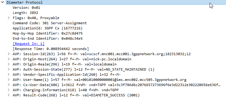
The Server-Assignment-Request/Answer commands are used so a SIP Server can indicate to a Diameter server that it is serving a subscriber and pull the profile information of the subscriber.
Basics:
The RFC’s definition is actually pretty succinct as to the function of the Server-Assignment Request/Answer:
The main functions of the Diameter SAR command are to inform the Diameter server of the URI of the SIP server allocated to the user, and to store or clear it from the Diameter server.
Additionally, the Diameter client can request to download the user profile or part of it.
The Server-Assignment-Request/Answer commands are sent by a S-CSCF to indicate to the Diameter server that it is now serving a specific subscriber, (This information can then be queried using the Location-Info-Request commands) and get the subscriber’s profile, which contains the details and identities of the subscriber.
Typically upon completion of a successful SIP REGISTER dialog (Multimedia-Authentication Request), the SIP Server (S-CSCF) sends the Diameter server a Server-Assignment-Request containing the SIP Username / Domain (referred to as an Address on Record (SIP-AOR) in the RFC) and the SIP Server (S-CSCF)’s SIP-Server-URI.
The Diameter server looks at the SIP-AOR and ensures there are not currently any active SIP-Server-URIs associated with that AoR. If there are not any currently active it then stores the SIP-AOR and the SIP-Server-URI of the SIP Server (S-CSCF) serving that user & sends back a Server-Assignment-Answer.
For most request the Subscriber’s profile is also transfered to the S-SCSF in the Server-Assignment-Answer command.
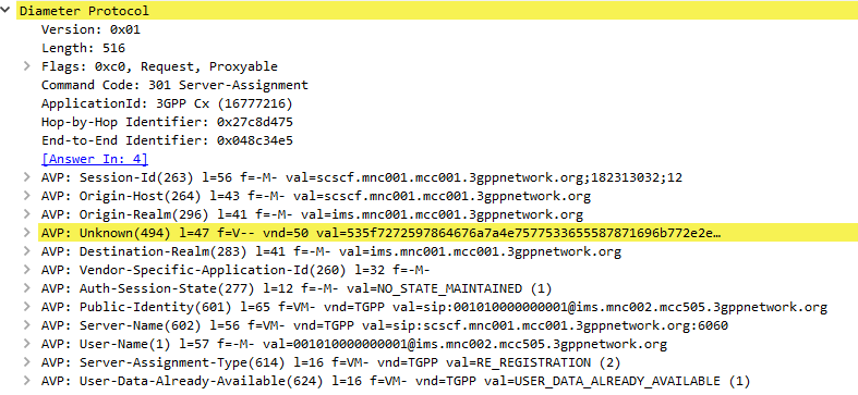
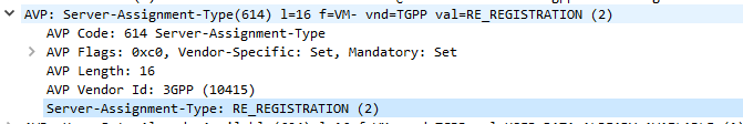
SIP-Server-Assignment-Type AVP
The same Server-Assignment-Request command can be used to register, re-register, remove registration bindings and pull the user profile, through the information in the SIP-Server-Assignment-Type AVP (375),
Common values are:
NO_ASSIGNMENT (0) – Used to pull just the user profile
The Cx-User-Data profile contains the subscriber’s profile from the Diameter server in an XML formatted dataset, that is contained as part of the Server-Assignment-Answer in the Cx-User-Data AVP (606).
The profile his tells the S-CSCF what services are offered to the subscriber, such as the allowed SIP Methods (ie INVITE, MESSAGE, etc), and how to handle calls to the user when the user is not registered (ie send calls to voicemail if the user is not there).
There’s a lot to cover on the user profile which we’ll touch on in a later post.
These posts focus on the use of Diameter and SIP in an IMS / VoLTE context, however these practices can be equally applied to other networks.
The Location-Information-Request/Answer commands are used so a SIP Server query a Diameter to find which P-CSCF a Subscriber is being served by
Basics:
The RFC’s definition is actually pretty succinct as to the function of the Server-Assignment Request/Answer:
The Location-Info-Request is sent by a Diameter Multimedia client to a Diameter Multimedia server in order to request name of the server that is currently serving the user.Reference: 29.229-
The Location-Info-Request is sent by a Diameter Multimedia client to a Diameter Multimedia server in order to request name of the server that is currently serving the user.
Reference: TS 29.229
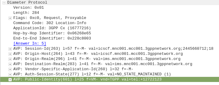
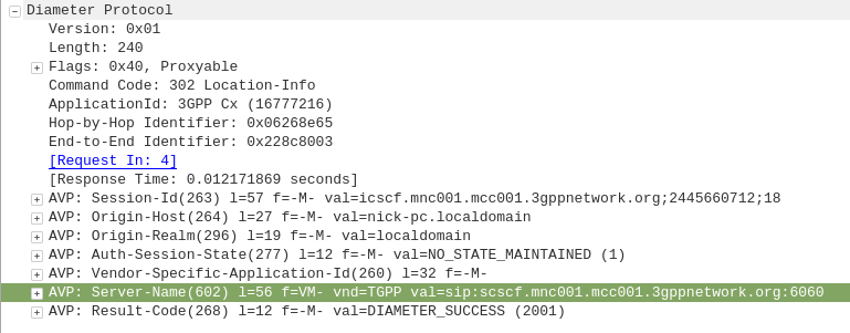
The Location-Info-Request commands is sent by an I-CSCF to the HSS to find out from the Diameter server the FQDN of the S-CSCF serving that user.
The Public-Identity AVP (601) contains the Public Identity of the user being sought.
Here you can see the I-CSCF querying the HSS via Diameter to find the S-CSCF for public identity 12722123
The Diameter server sends back the Location-Info-Response containing the Server-Name AVP (602) with the FQDN of the S-CSCF.
Packet Capture
I’ve included a packet capture of these Diameter Commands from my lab network which you can find below.
These posts focus on the use of Diameter and SIP in an IMS / VoLTE context, however these practices can be equally applied to other networks.
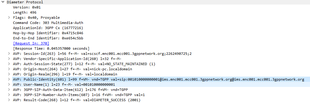
The Multimedia-Authentication-Request/Answer commands are used to Authenticate subscribers / UAs using a variety of mechanisms such as straight MD5 and AKAv1-MD5.
Basics:
When a SIP Server (S-CSCF) receives a SIP INVITE, SIP REGISTER or any other SIP request, it needs a way to Authenticate the Subscriber / UA who sent the request.
We’ve already looked at the Diameter User-Authorization-Request/Answer commands used to Authorize a user for access, but the Multimedia-Authentication-Request / Multimedia-Authentication-Answer it used to authenticate the user.
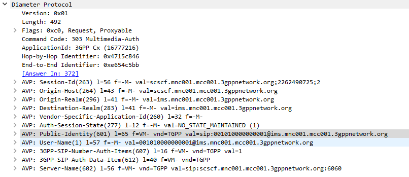
The SIP Server (S-CSCF) sends a Multimedia-Authentication-Request to the Diameter server, containing the Username of the user attempting to authenticate and their Public Identity.
The Diameter server generates “Authentication Vectors” – these are Precomputed cryptographic challenges to challenge the user, and the correct (“expected”) responses to the challenges. The Diameter puts these Authentication Vectors in the 3GPP-SIP-Auth-Data (612) AVP, and sends them back to the SIP server in the Multimedia-Authentication-Answer command.
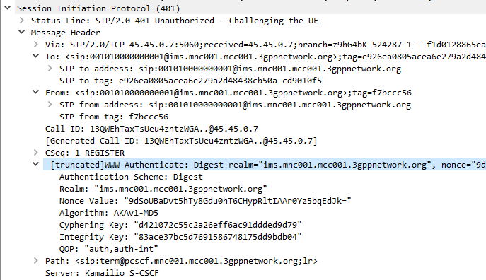
The SIP server sends the Subscriber / UA a SIP 401 Unauthorized response to the initial request, containing a WWW-Authenticate header containing the challenges.
SIP 401 Response with WWW-Authenticate header populated with values from Multimedia-Auth-Answer
The Subscriber / UA sends back the initial request with the WWW-Authenticate header populated to include a response to the challenges. If the response to the challenge matches the correct (“expected”) response, then the user is authenticated.
Multimedia-Authentication-Request
Multimedia-Authentication-Answer
I always find it much easier to understand what’s going on through a packet capture, so here’s a packet capture showing the two Diameter commands,
Note: There is a variant of this process allows for stateless proxies to handle this by not storing the expected authentication values sent by the Diameter server on the SIP Proxy, but instead sending the received authentication values sent by the Subscriber/UA to the Diameter server to compare against the expected / correct values.
The Cryptography
The Cryptography for IMS Authentication relies on AKAv1-MD5 which I’ve written about before,
Essentially it’s mutual network authentication, meaning the network authenticates the subscriber, but the subscriber also authenticates the network.
A lot of people think there’s a one-to-one relationship between a registration Address on Record, and a username.
That doesn’t have to be the case, there are some platforms that only allow a single registration for a single username, but the RFC itself allows multiple registrations for a single username.
REGISTER requests add, remove, and query bindings.
A REGISTER request can add a new binding between an address-of-record and one or more contact addresses.
Registration on behalf of a particular address-of-record can be performed by a suitably authorized third party.
A client can also remove previous bindings or query to determine which bindings are currently in place for an address-of-record.
Let’s say you’ve got a SIP phone on your desk at the office and at home.
What we could do is create a different username and password for home & work, and then setup some time based forward rules to ring the office from 9-5 and home outside of that.
You could register both with the same username and password, and then unplug the one at home before you leave to work, get to work, plug in your office phone, unplug it before you leave to go home, and when you get home plug back in your home phone, or if multi-device registration is supported, register both and have incoming calls ring on both.
Admittedly, platforms that support this are the exception, not the rule, but the RFC does allow it.
The other little known feature in SIP Registration is that you can query the SIP Registrar to get the list of Addresses on Record.
So there you go, factoids about SIP REGISTER method!
I’ve been working on a ePDG for VoWiFi access to my IMS core.
This has led to a bit of a deep dive into GTP (easy enough) and GTPv2 (Bit harder).
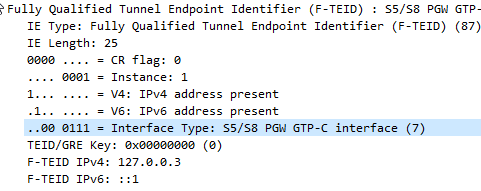
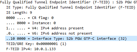
The Fully Qualified Tunnel Endpoint Identifier includes an information element for the Interface Type, identified by a two digit number.
Here we see S2b is 32
In the end I found the answer in 3GPP TS 29.274, but thought I’d share it here.
0
S1-U eNodeB GTP-U interface
1
S1-U SGW GTP-U interface
2
S12 RNC GTP-U interface
3
S12 SGW GTP-U interface
4
S5/S8 SGW GTP-U interface
5
S5/S8 PGW GTP-U interface
6
S5/S8 SGW GTP-C interface
7
S5/S8 PGW GTP-C interface
8
S5/S8 SGW PMIPv6 interface (the 32 bit GRE key is encoded in 32 bit TEID field and since alternate CoA is not used the control plane and user plane addresses are the same for PMIPv6)
9
S5/S8 PGW PMIPv6 interface (the 32 bit GRE key is encoded in 32 bit TEID field and the control plane and user plane addresses are the same for PMIPv6)
10
S11 MME GTP-C interface
11
S11/S4 SGW GTP-C interface
12
S10 MME GTP-C interface
13
S3 MME GTP-C interface
14
S3 SGSN GTP-C interface
15
S4 SGSN GTP-U interface
16
S4 SGW GTP-U interface
17
S4 SGSN GTP-C interface
18
S16 SGSN GTP-C interface
19
eNodeB GTP-U interface for DL data forwarding
20
eNodeB GTP-U interface for UL data forwarding
21
RNC GTP-U interface for data forwarding
22
SGSN GTP-U interface for data forwarding
23
SGW GTP-U interface for DL data forwarding
24
Sm MBMS GW GTP-C interface
25
Sn MBMS GW GTP-C interface
26
Sm MME GTP-C interface
27
Sn SGSN GTP-C interface
28
SGW GTP-U interface for UL data forwarding
29
Sn SGSN GTP-U interface
30
S2b ePDG GTP-C interface
31
S2b-U ePDG GTP-U interface
32
S2b PGW GTP-C interface
33
S2b-U PGW GTP-U interface
I also found how this data is encoded on the wire is a bit strange,
In the example above the Interface Type is 7,
This is encoded in binary which give us 111.
This is then padded to 6 bits to give us 000111.
This is prefixed by two additional bits the first denotes if IPv4 address is present, the second bit is for if IPv6 address is present.
Bit 1
Bit 2
Bit 3-6
IPv4 Address Present
IPv4 Address Present
Interface Type
1
1
000111
This is then encoded to hex to give us 87
Here’s my Python example;
interface_type = int(7)
interface_type = "{0:b}".format(interface_type).zfill(6)   #Produce binary bits
ipv4ipv6 = "10" #IPv4 only
interface_type = ipv4ipv6 + interface_type #concatenate the two
interface_type  = format(int(str(interface_type), 2),"x") #convert to hex
I’ve been working for some time on open source mobile network cores, and one feature that has been a real struggle for a lot of people (Myself included) is getting VoLTE / IMS working.
Here’s some of the issues I’ve faced, and the lessons I learned along the way,
Sadly on most UEs / handsets, there’s no “Make VoLTE work now” switch, you’ve got a satisfy a bunch of dependencies in the OS before the baseband will start sending SIP anywhere.
Get the right Hardware
Your eNB must support additional bearers (dedicated bearers I’ve managed to get away without in my testing) so the device can setup an APN for the IMS traffic.
Sadly at the moment this rules our Software Defined eNodeBs, like srsENB.
ISIM – When you thought you understood USIMs – Guess again
According to the 3GPP IMS docs, an ISIM (IMS SIM) is not a requirement for IMS to work.
However in my testing I found Android didn’t have the option to enable VoLTE unless an ISIM was present the first time.
In a weird quirk I found once I’d inserted an ISIM and connected to the VoLTE network, I could put a USIM in the UE and also connect to the VoLTE network.
Obviously the parameters you can set on the USIM, such as Domain, IMPU, IMPI & AD, are kind of “guessed” but the AKAv1-MD5 algorithm does run.
Getting the APN Config Right
There’s a lot of things you’ll need to have correct on your UE before it’ll even start to think about sending SIP messaging.
I was using commercial UE (Samsung handsets) without engineering firmware so I had very limited info on what’s going on “under the hood”. There’s no “Make VoLTE do” tickbox, there’s VoLTE enable, but that won’t do anything by default.
If your P-GW doesn’t know the IP of your P-CSCF, it’s not going to be able to respond to it in the Protocol Configuration Options (PCO) request sent by the UE with that nice new bearer for IMS we just setup.
There’s no way around Mutual Authentication
Coming from a voice background, and pretty much having RFC 3261 tattooed on my brain, when I finally got the SIP REGISTER request sent to the Proxy CSCF I knocked something up in Kamailio to send back a 200 OK, thinking that’d be the end of it.
For any other SIP endpoint this would have been fine, but IMS Clients, nope.
Reading the specs drove home the same lesson anyone attempting to setup their own LTE network quickly learns – Mutual authentication means both the network and the UE need to verify each other, while I (as the network) can say the UE is OK, the UE needs to check I’m on the level.
I saw my 401 response go back to the UE and then no response. Nada.
This led to my next lesson…
There’s no way around IPsec
According to the 3GPP docs, support for IPsec is optional, but I found this not to be the case on the handsets I’ve tested.
After sending back my 401 response the UE looks for the IPsec info in the 401 response, then tries to setup an IPsec SA and sends ESP packets back to the P-CSCF address.
Even with my valid AKAv1-MD5 auth, I found my UE wasn’t responding until I added IPsec support on the P-CSCF, hence why I couldn’t see the second REGISTER with the Authentication Info.
After setting up IPsec support, I finally saw the UE’s REGISTER with the AKAv1-MD5 authentication, and was able to send a 200 OK.
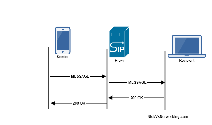
People think SIP they think VoIP & phone calls, but SIP it’s the Phone Call Initiation Protocol it’s the Session Initiation Protocol – Sure VoIP guys like me love SIP, but it’s not just about VoIP.
Have you sent an SMS on a modern mobile phone recently? Chances are you sent a SMS over SIP using SIP MESSAGE method.
So let’s look a bit at SIP SIMPLE, the catchily titled acronym translates to Session Initiation Protocol for Instant Messaging and Presence Leveraging Extensions (Admittedly less catchy in it’s full form).
There’s two way SIP SIMPLE can be used to implement Instant Messaging, Paging Mode with each message sent as a single transaction, and Session Mode where a session is setup between users and IMs exchanged with the same Call ID / transaction.
I’m going to cover the Paging Mode implementation because it’s simpler easier to understand.
Before we get too far this is another example of confusing terminology, let’s just clear this up; According to the RFC any SIP request is a SIP Message, like a SIP OPTIONS message, a SIP INVITE message. But the method of a SIP INVITE message is INVITE, the method of a SIP OPTIONS message is OPTIONS. There’s a SIP MESSAGE method, meaning you can send a SIP MESSAGE message using the MESSAGE method. Clear as mud? I’ll always refer to the SIP Method in Capitals, like MESSAGE, INVITE, UPDATE, etc.
The SIP MESSAGE method looks / acts very similar to a SIP INVITE, in that it’s got all the standard SIP headers, but also a Message Body, in which our message body lives (funny about that), typically we’ll send messages using the Content-Type: text/plain to denote we’re sending a plaintext message.
Example MESSAGE Message Flow
Like a SIP OPTIONS Method, the MESSAGE method is simply answered with a 200 OK (No Ack).
Let’s have a look at how the MESSAGE message looks:
For most Voice / Telco engineers IPsec is a VPN technology, maybe something used when backhauling over an untrusted link, etc, but voice over IP traffic is typically secured with TLS and SRTP.
IMS / Voice over LTE handles things a bit differently, it encapsulates the SIP & RTP traffic between the UE and the P-CSCF in IPsec Encapsulating Security Payload (ESP) payloads.
In this post we’ll take a look at how it works and what it looks like.
It’s worth noting that Kamailio recently added support for IPsec encapsulation on a P-CSCF, in the IMS IPSec-Register module. I’ll cover usage of this at a later date.
The Message Exchange
The exchange starts off looking like any other SIP Registration session, in this case using TCP for transport. The UE sends a REGISTER to the Proxy-CSCF which eventually forwards the request through to a Serving-CSCF.
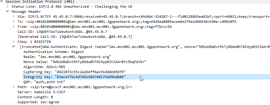
This is where we diverge from the standard SIP REGISTER message exchange. The Serving-CSCF generates a 401 Unauthorized response, containing an authentication challenge in the WWW-Authenticate header, and also a Ciphering Key & Integrity Key (ck= and ik=) also in the WWW-Authenticate header.
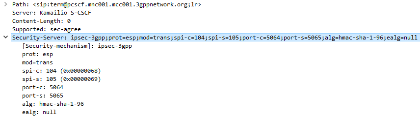
The Serving-CSCF sends the Proxy-CSCF the 401 response it created. The Proxy-CSCF assigns a SPI for the IPsec ESP to use, a server port and client port and indicates the used encryption algorithm (ealg) and algorithm to use (In this case HMAC-SHA-1-96.) and adds a new header to the 401 Unauthorized called Security–Server header to share this information with the UE.
The Proxy-CSCF also strips the Ciphering Key (ck=) and Integrity Key (ik=) headers from the SIP authentication challenge (WWW-Auth) and uses them as the ciphering and integrity keys for the IPsec connection.
Finally after setting up the IPsec server side of things, it forwards the 401 Unauthorized response onto the UE.
Upon receipt of the 401 response, the UE looks at the authentication challenge.
If the network is considered authenticated by the UE it generates a response to the Authentication Challenge, but it doesn’t deliver it over TCP. Using the information generated in the authentication challenge the UE encapsulates everything from the network layer (IPv4) up and sends it to the P-CSCF in an IPsec ESP.
Communication between the UE and the P-CSCF is now encapsulated in IPsec.
Wireshark trace of IPsec IMS Traffic between UE and P-CSCF