Category Archives: EPC

Screenshot of packet capture of Diameter Multimedia-Auth-Request (Diameter Command Code 303) used for IMS authentication

Diameter and SIP: Multimedia-Authentication-Request/Answer

These posts focus on the use of Diameter and SIP in an IMS / VoLTE context, however these practices can be equally applied to other networks.

The Multimedia-Authentication-Request/Answer commands are used to Authenticate subscribers / UAs using a variety of mechanisms such as straight MD5 and AKAv1-MD5.

Basics:

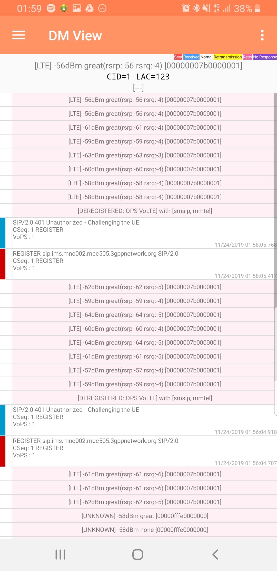
When a SIP Server (S-CSCF) receives a SIP INVITE, SIP REGISTER or any other SIP request, it needs a way to Authenticate the Subscriber / UA who sent the request.

We’ve already looked at the Diameter User-Authorization-Request/Answer commands used to Authorize a user for access, but the Multimedia-Authentication-Request / Multimedia-Authentication-Answer it used to authenticate the user.

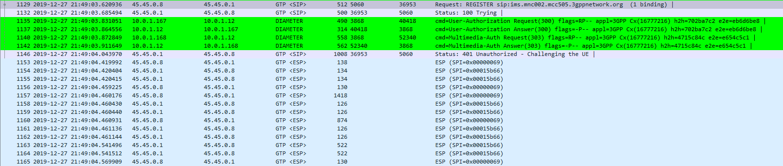
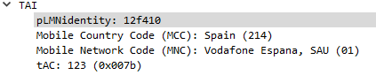
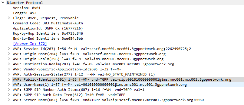
The SIP Server (S-CSCF) sends a Multimedia-Authentication-Request to the Diameter server, containing the Username of the user attempting to authenticate and their Public Identity.

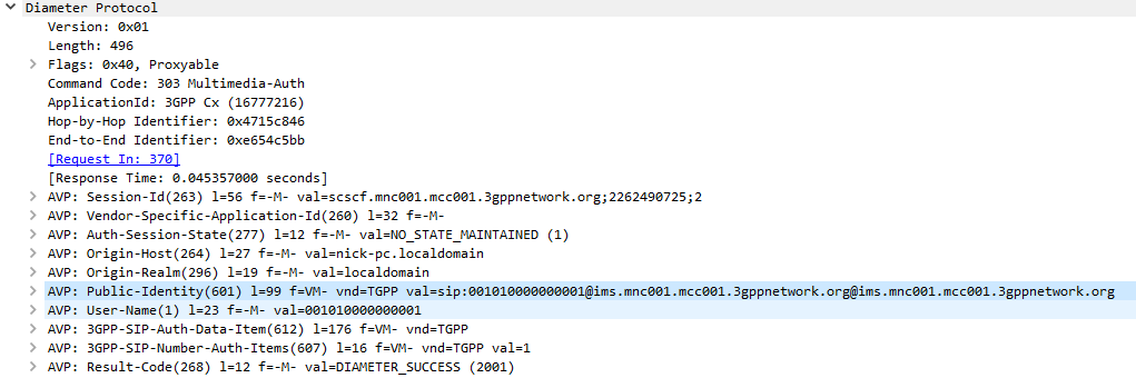
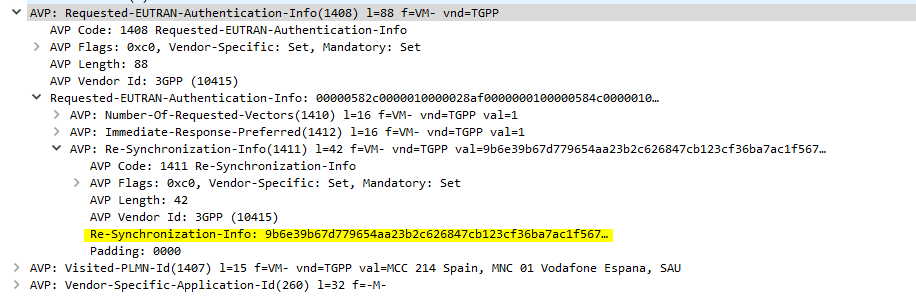
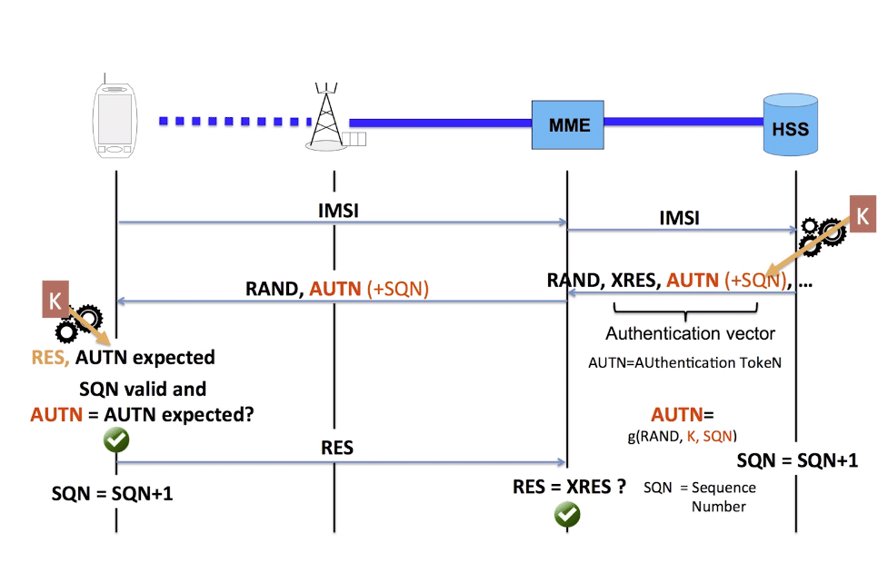
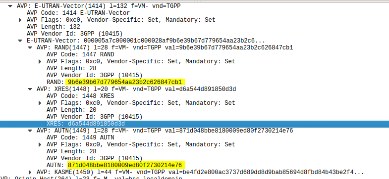
The Diameter server generates “Authentication Vectors” – these are Precomputed cryptographic challenges to challenge the user, and the correct (“expected”) responses to the challenges. The Diameter puts these Authentication Vectors in the 3GPP-SIP-Auth-Data (612) AVP, and sends them back to the SIP server in the Multimedia-Authentication-Answer command.

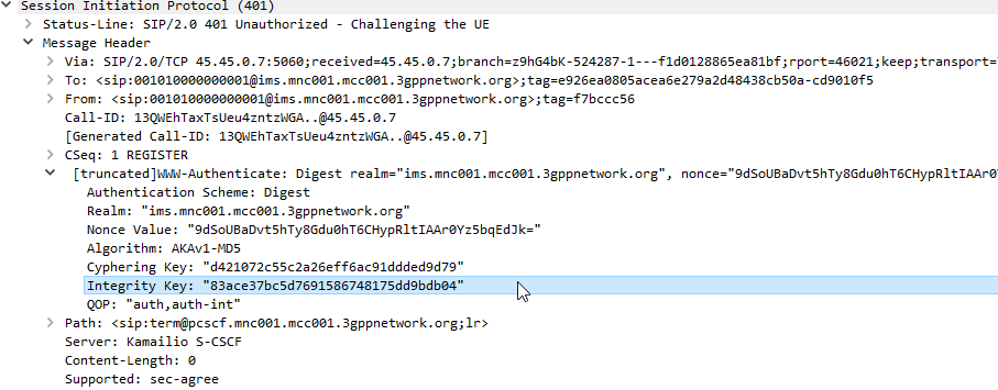
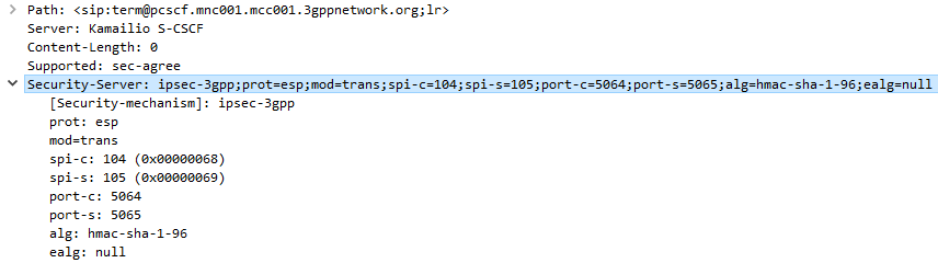
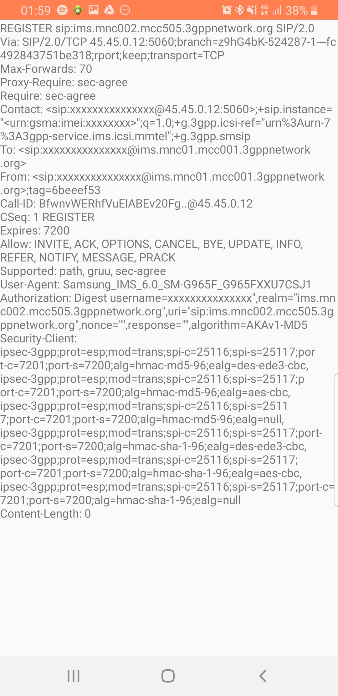
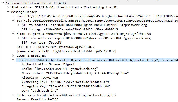
The SIP server sends the Subscriber / UA a SIP 401 Unauthorized response to the initial request, containing a WWW-Authenticate header containing the challenges.

SIP 401 Response with WWW-Authenticate header populated with values from Multimedia-Auth-Answer

The Subscriber / UA sends back the initial request with the WWW-Authenticate header populated to include a response to the challenges. If the response to the challenge matches the correct (“expected”) response, then the user is authenticated.

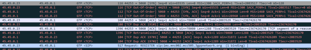
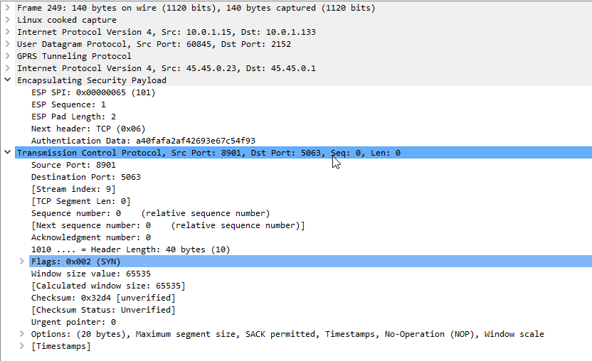
I always find it much easier to understand what’s going on through a packet capture, so here’s a packet capture showing the two Diameter commands,

Note: There is a variant of this process allows for stateless proxies to handle this by not storing the expected authentication values sent by the Diameter server on the SIP Proxy, but instead sending the received authentication values sent by the Subscriber/UA to the Diameter server to compare against the expected / correct values.

The Cryptography

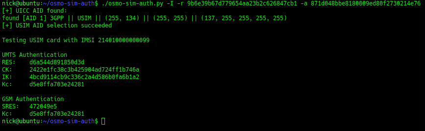
The Cryptography for IMS Authentication relies on AKAv1-MD5 which I’ve written about before,

Essentially it’s mutual network authentication, meaning the network authenticates the subscriber, but the subscriber also authenticates the network.

LTE USIM Authentication - Mutual Authentication of the Network and Subscriber

Other Diameter Cx (IMS) Calls

User-Authorization-Request / User-Authorization-Answer
Server-Assignment-Request / Server-Assignment-Answer
Location-Info-Request / Location-Info-Answer
Multimedia-Auth-Request / Multimedia-Auth-Answer
Registration-Termination-Request / Registration-Termination-Answer
Push-Profile-Request / Push-Profile-Answer

References:

3GPP Specification #: 29.229

RFC 4740 – Diameter Session Initiation Protocol (SIP) Application

Connecting any 3rd Party HSS to Open5GS MME

You may want to connect Open5GS’ MME to a different Home Subscriber Server (HSS),

To do it we need a few bits of information:

  • The Domain Name of the HSS
  • The Realm of the HSS
  • The IP of the HSS
  • The Transport Used (TCP/SCTP)
  • If TLS is used

With these bits of information we can go about modifying the Open5GS MME config to talk to our different HSS.

Edit FreeDiameter Config

The config for the Open5GS MME’s Diameter peers is handled by the FreeDimaeter library,

You can find it’s config files in:

/etc/freediameter/mme.conf

We’ll start by changing the realm to match the realm of the HSS and the identity to match the identity configured as the MME peer on the HSS.

We’ll next set the ListenOn address to be a reachable IP address isntead of just a loopback address,

If you’re using TLS you’ll need to put your certificates and private key files into the TLS config,

Finally we’ll put our HSS details in the Peer Configuration;

Once all this is done we’ll need to restart our MME and you should see the Diameter Capabilities Exchange / Answer commands between the HSS and the MME if all was successful,

systemctl restart open5gs-mmed

In the /var/log/open5gs/mme.log I can now see:

05/11 23:25:46.896: [app] INFO: MME initialize…done (../src/mme/app-init.c:33)
05/11 23:25:46.898: [diam] INFO: CONNECTED TO 'hss.nickexamplenet' (SCTP,soc#15): (../lib/diameter/common/logger.c:108)

And that’s it! We’re connected to an external HSS.

Through the freeDiameter config file you can specify multiple ConnectPeer() entries to connect to multiple HSS (like a pool of them), and requests will be distributed evenly between them.

SMS over SGi interface on Open5GS MME and OsmoMSC

Sending SMS in Open5GS LTE Networks using the SGs Interface and OsmoMSC with SMSoS

We recently covered Circuit Switched fallback between LTE EUTRAN and GSM GERAN, and the SGs interface between the MME and the MSC.

One nifty feature of this interface is that you can send SMS using the MSC to switch the SMS traffic and the LTE/EUTRAN to transfer the messaging.

This means you don’t need Circuit Switched Fallback to send or receive SMS on LTE.

I assume this functionality was added to avoid the signalling load of constantly changing RAN technologies each time a subscriber sent or received an SMS, but I couldn’t find much about it’s history.

In order to get this to work you’ll essentially need the exact same setup I outlined in my CSFB example (Osmo-MSC, Osmo-STP, Osmo-HLR populated with the IMSI and MSISDN values you want to use for SMS), although you won’t actually need a GERAN / GSM radio network.

Once that’s in place you can just send SMS between subscribers,

Plus from the VTY terminal of OsmoMSC you can send SMS too:

OsmoMSC# subscriber msisdn 61487654321 sms sender msisdn 61412341234 send Hello World
Using the SGs interface for Circuit Switched Fallback (CSFB) Calls from LTE falling back to GSM

OsmoMSC and Open5GS MME – SGs Interface for InterRAT Handover & SMS

I’ve talked about how LTE’s EUTRAN / EPC has no knowledge about voice calls or SMS and instead relies on IMS/VoLTE for these services.

Circuit Switched Fallback allows UEs to use a 2G or 3G network (Circuit Switched network) if their device isn’t connected to the IMS network to make calls as the 2G/3G network can handle the voice call or SMS routing via the Mobile Switching Center in the 2G/3G network.

However for incoming calls destined to the UE (Mobile Terminated) the MSC needs a way to keep track of which MME is serving the UE so it can get a message to the MME and the MME can relay it to the UE, to tell it to drop to a 2G or 3G network (Circuit Switched network).

The signalling between the MME (In the LTE EPC) and the MSC (In the GSM/UTRAN core) is done over the SGs interface.

While the SGs interface is primarily for managing user location state across multiple RAN types, it’s got a useful function for sending SMS over SGi, allowing users on an LTE RAN to send SMS via the MSC of the 2G/3G network (GSM/UTRAN core).

How it Works:

When a UE connects to the LTE RAN (EUTRAN) the MME signals the GSM/UMTS MSC with an SGsAP-LOCATION-UPDATE-REQUEST,

This request includes the IMSI of the subscriber that just attached and the FQDN of the MME serving that UE.

The MSC now knows that IMSI 001010000000003 is currently on LTE RAN served by MME mmec01.mmegi0002.mme.epc.mnc001.mcc001.3gppnetwork.org,

If a call or SMS comes into the MSC destined for the MSISDN of that IMSI, the MSC can page the UE on the LTE RAN to tell it to do an inter-RAN handover to GSM/UMTS.

Setting it Up

In order to get this working you’ll need OsmoMSC in place, your subscribers to exist on OsmoHLR and the LTE HSS – For example Open5GS-HSS.

If you’re not familiar with OsmoMSC or the Osmocom stack I did a series of posts covering them you can find here. If you want to get this setup I’d suggest following the posts on installing the Osmocom Software, setting up the MSC, the STP and the HLR.

Once you’ve done that the additional config on OsmoMSC is fairly simple, we just define a new SGs interface to listen on:

OsmoMSC Config:

sgs
  local-port 29118
  local-ip 0.0.0.0
  vlr-name vlr.msc001.mnc001.mcc001.3gppnetwork.org
end

On the Open5GS side we’ve got to include the SGs info the MME config. Keep in mind the Tracking Area Code (TAC) in LTE must exist as the Location Area code (LAC) in GSM, here’s an extract of the MME section of YAML config in the Open5GS MME config:

mme:
    freeDiameter: /etc/freeDiameter/mme.conf
    s1ap:
    gtpc:

    sgsap:
      addr: 10.0.1.9
      map:
        tai:
          plmn_id:
            mcc: 001
            mnc: 01
          tac: 7
        lai:
          plmn_id:
            mcc: 001
            mnc: 01
          lac: 7


    gummei: 
      plmn_id:
        mcc: 001
        mnc: 01
      mme_gid: 2
      mme_code: 1
    tai:
      plmn_id:
        mcc: 001
        mnc: 01
      tac: 7
    security:
        integrity_order : [ EIA1, EIA2, EIA0 ]
        ciphering_order : [ EEA0, EEA1, EEA2 ]
    network_name:
        full: Open5GS
sgw:
    gtpc:
      addr: 127.0.0.2
      addr: 10.0.1.252

pgw:
    gtpc:
      addr:
        - 127.0.0.3
        - ::1

Neighbours Configured

The EUTRAN will need to advertise the presence of it’s GERAN neighbours and vise-versa so the UE/terminals know what ARFCN to move to so they don’t need to scan for the presence of other RATs when performing the handover.

Setting this up will depend on your eNB / BSC and goes beyond the scope of this post.

I’ll cover setting up neighbours in a later post as it’s a big topic.

If you don’t have neighbours configured, the handover will still work but will be much slower as the UE will have to scan to find the serving cell it’s reselecting to.

Example Packet Capture

Kamailio Proxy-CSCF Pull

I had a few headaches getting the example P-CSCF example configs from the Kamailio team to run, recent improvements with the IPsec support and code evolution meant that the example config just didn’t run.

So, after finally working out the changes I needed to make to get Kamailio to function as a P-CSCF, I took the plunge and made my first pull request on the Kamailio project.

And here it is!

https://github.com/kamailio/kamailio/pull/2203

It’s now in the master branch, so if you want to setup a P-CSCF using Kamailio, give it a shot, as the example config finally works!

Multi Operator Core-Networks (MOCN) for RAN Sharing

MOCN is one of those great concepts I’d not really come across,

Multi-tenancy on the RAN side of the network, allowing an eNB to broadcast multiple PLMN IDs (MCC/MNC) in the System Information Block (SIB).

It allows site sharing not just on the tower itself, but site sharing on the RAN side, allowing customers of MNO A to see themselves connected to MNO A, and customers from MNO B see themselves as connected to MNO B, but they’re both connected to the same RAN hardware.

Setup in my lab was a breeze; your RAN hardware will probably be different.

In terms of signaling it’s a standard S1AP Setup Request except with multiple broadcast PLMN keys:

Now when I run a manual cell selection on my UE I can see the PLMN 460/11 as well as the Open5gs 00101 PLMN:

Forsk Atoll 101 – Part 3 – Manual Site Placement

In our last post we talked about getting our geospatial data right, and in our first post we covered the basics of adding sites and transmitters.

There’s a bit of a chicken-and-egg problem with site placement, antenna orientation, type and down-tilt.

If all our sites were populated and in place, we could look at optimizing coverage by changing azimuths / orientations, plug in our data and run some predictions / modeling and coming up with some solutions. Likewise if we’ve already done that we might want to calculate ideal down-tilt angles to get the most out of network.

But we’ve got no sites, no transmitters and no coverage predictions yet, so we’re probably going to need to ask ourselves a more basic, but harder question: Where will we put the cell sites?

To keep this easy we’ll focus on providing the South Western corner of the Island, a town called Tankerton, with only 3 cell sites.

Manual Site Selection

In the very first post we put up a few sites, we’ll do the same, let’s place 3 sites in the bottom right of the island and attempt to provide contiguous coverage for the town with them;

We’ll pick our Station Template and set it to FDD Rural as this is pretty remote.

Next we’ll add some sites and transmitters:

Click to place it on the map and add our cell sites;

When we’re looking at where to place it, it’s good to remember that height (elevation) is good (To an extent), so when looking at where to place sites, keep an eye on the Z (Height) value in the bottom right, and try and pick sites with a good elevation.

Setting Computation Zone

As we’re only focusing on a small part of the island we’ll set a Computation Zone to limit the calculations / computations Atoll has to do to a set region.

I’ve chosen to draw a Polygon around the area, but you could also just get away with drawing a Rectangle, around the area we’re interested in.

This just constrains everything so we’re only crunching numbers inside that area.

Predictions

So now we’ve put our 3 sites out & constrained to the Tankerton area, let’s see how much of the area we’ve covered, we’ll jump to the Network tab, right click on Predictions and select New Prediction

There’s a lot of predictions we can run, but we’ll go simple and select Effective Service Area Analysis (UL + DL) & click Calculate

Atoll will crunch the numbers and give us a simple overlay, showing the areas with and without coverage.

The areas in red are predicted to have coverage, and the areas with no shading will be our blackspots / “notspots”.

We’ve covered most of the area, but we can improve.

Manually Tweaking Attributes

So there’s still some holes in our coverage, so let’s adjust the azimuth of some of the antennas and see if we can fill them.

Click on each of the arrows on the site, each of these represents an antenna / cell and we can change the angles.

So after a bit of fiddling I think I’ve got a better antenna azimuth for each of the sectors on each of my 3 sites.

Let’s compare that to what we had before to see if we’ve made it better or worse,

We’ll Duplicate the Effective Service Area Analysis prediction we created before & calculate it.

To make viewing a bit easier we’ll edit the properties of the copy and set it to a different colour:

Now I can see at a glance how much better we’re looking;

The obvious problem here is I could tweak and tweak and improve some things, make others worse, and we’d be here forever.

Luckily Atoll can do a better job of fiddling with each parameter for us and selecting the configuration that leads to the best performance in our RAN.

Automatic Cell Planning

Enter Automatic Cell Planning, to adjust the parameters we set to find the most optimal setup,

We’ll right click on ACP – Automatic Cell Planning and create a new one.

From here we set how many iterations we want to try out (more leads to better results but takes longer to compute), the parameters we want to change (ie Azimuth, Tilt, Antenna type, etc).

Setting number of iterations – Higher leads to better results but takes longer to calculate and has diminishing returns
We’ll allow the Tilt (Electrical & Mechanical) to be adjusted as well as the Azimuth of each antenna.

When you’ve set the parameters you want, click Run and Atoll will start running through possible parameter combinations and measuring how they perform.

Once it’s run you’ll be able to view the Optomization

The report shows you the results, improvements in RSSI and RSSQ;

Here we can see we boosted the RSRQ (The quality of the signal) by 9.5%, but had to sacrifice RSRP (Signal power) by 1%.

Sacrificies have to be made, and if you’re happy with this you can view the details of the changes, and commit the adjustments.

Committing the changes adjusts all the Transmitters in the area to the listed values, after which we can run our Predictions again to compare like we did earlier.

So that’s what we’ve got when we randomly place sites, we can use Atoll to optomize what we’ve already got, but what if we left the picking of cell sites up to Atoll to look for better options?

In our next post we’ll look at Site Selection using ACP, and constraining it. This means we can tell Atoll to just find the best sites, or load in a list of possible sites and let Atoll determine which are the best candidates.

Ansible for Scaling and Deployment of Evolved Packet Core NEs

There’s always lots of talk of Network Function Virtualization (NFV) in the Telco space, but replacing custom hardware with computing resources is only going to get you so far, if every machine has to be configured manually.

Ansible is a topic I’ve written a little bit about in terms of network automation / orchestration.

I wanted to test limits of Open5gs EPC, which led me to creating a lot of Packet Gateways, so I thought I’d share a little Ansible Playbook I wrote for deploying P-GWs.

It dynamically sets the binding address and DHCP servers, and points to each PCRF in the defined pool.

You can obviously build upon this too, creating another playbook to deploy PCRFs, MMEs and S-GWs will allow you to reference the hosts in each group to populate the references.

The Playbook

---
- name: Install & configure Open5GS EPC (P-GW)

  hosts: epc

  become: yes
  become_method: sudo

  vars:
    dns_servers: ['8.8.8.8','1.1.1.1']
    diameter_realm: 'nickvsnetworking.com'
    pcrf_hosts: ['pcrf1.nickvsnetworking.com', 'pcrf2.nickvsnetworking.com']
  tasks:
    - name: Set Hostname to {{inventory_hostname}}
      hostname:
        name: "{{inventory_hostname}}"
      register: rebootrequired

    - name: Updating hotnamectl
      command: "hostnamectl set-hostname {{inventory_hostname}}"
      become: True
      become: True
      when: rebootrequired.changed

    - name: Reboot VM due to Hostname Change
      reboot:
        reboot_timeout: 180
      when: rebootrequired.changed

    - name: Add Software common
      apt:
        name: software-properties-common

    - name: Add Repository
      apt_repository:
        repo: ppa:open5gs/latest

    - name: Install Open5gs P-GW
      apt:
        update_cache: true
        name: open5gs-pgw

    - name: Fill in GTP Addresses in Config
      template:
        src: pgw.yaml.j2
        dest: /etc/open5gs/pgw.yaml
        backup: true
      register: config_changed

    - name: Fill in P-GW Diameter Config
      template:
        src: pgw.conf.j2
        dest: /etc/freeDiameter/pgw.conf
        backup: true
      register: config_changed


    - name: Restart P-GW Service if Config Changed
      service:
        name: open5gs-pgwd
        state: restarted
      when: config_changed.changed

Jinja2 Template

P-GW Config (pgw.yaml.jn2)

logger:
    file: /var/log/open5gs/pgw.log

parameter:

pgw:
    freeDiameter: /etc/freeDiameter/pgw.conf
    gtpc:
      - addr: {{hostvars[inventory_hostname]['ansible_default_ipv4']['address']}}

    gtpu:
      - addr: {{hostvars[inventory_hostname]['ansible_default_ipv4']['address']}}

    ue_pool:
      - addr: 45.45.0.1/16
      - addr: cafe::1/64
    dns:
{% for dns in dns_servers %}
      - {{ dns }}
{% endfor %}

Diameter Config (pgw.conf.j2)

# This is a sample configuration file for freeDiameter daemon.

# Most of the options can be omitted, as they default to reasonable values.
# Only TLS-related options must be configured properly in usual setups.

# It is possible to use "include" keyword to import additional files
# e.g.: include "/etc/freeDiameter.d/*.conf"
# This is exactly equivalent as copy & paste the content of the included file(s)
# where the "include" keyword is found.


##############################################################
##  Peer identity and realm

# The Diameter Identity of this daemon.
# This must be a valid FQDN that resolves to the local host.
# Default: hostname's FQDN
#Identity = "aaa.koganei.freediameter.net";
Identity = "{{ inventory_hostname  }}.{{ diameter_realm }}";

# The Diameter Realm of this daemon.
# Default: the domain part of Identity (after the first dot).
#Realm = "koganei.freediameter.net";
Realm = "{{ diameter_realm }}";
##############################################################
##  Transport protocol configuration

# The port this peer is listening on for incoming connections (TCP and SCTP).
# Default: 3868. Use 0 to disable.
#Port = 3868;

# The port this peer is listening on for incoming TLS-protected connections (TCP and SCTP).
# See TLS_old_method for more information about TLS flavours.
# Note: we use TLS/SCTP instead of DTLS/SCTP at the moment. This will change in future version of freeDiameter.
# Default: 5868. Use 0 to disable.
#SecPort = 5868;

# Use RFC3588 method for TLS protection, where TLS is negociated after CER/CEA exchange is completed
# on the unsecure connection. The alternative is RFC6733 mechanism, where TLS protects also the
# CER/CEA exchange on a dedicated secure port.
# This parameter only affects outgoing connections.
# The setting can be also defined per-peer (see Peers configuration section).
# Default: use RFC6733 method with separate port for TLS.
#TLS_old_method;

# Disable use of TCP protocol (only listen and connect over SCTP)
# Default : TCP enabled
#No_TCP;

# Disable use of SCTP protocol (only listen and connect over TCP)
# Default : SCTP enabled
#No_SCTP;
# This option is ignored if freeDiameter is compiled with DISABLE_SCTP option.

# Prefer TCP instead of SCTP for establishing new connections.
# This setting may be overwritten per peer in peer configuration blocs.
# Default : SCTP is attempted first.
#Prefer_TCP;

# Default number of streams per SCTP associations.
# This setting may be overwritten per peer basis.
# Default : 30 streams
#SCTP_streams = 30;

##############################################################
##  Endpoint configuration

# Disable use of IP addresses (only IPv6)
# Default : IP enabled
#No_IP;

# Disable use of IPv6 addresses (only IP)
# Default : IPv6 enabled
#No_IPv6;

# Specify local addresses the server must bind to
# Default : listen on all addresses available.
#ListenOn = "202.249.37.5";
#ListenOn = "2001:200:903:2::202:1";
#ListenOn = "fe80::21c:5ff:fe98:7d62%eth0";
ListenOn = "{{hostvars[inventory_hostname]['ansible_default_ipv4']['address']}}";


##############################################################
##  Server configuration

# How many Diameter peers are allowed to be connecting at the same time ?
# This parameter limits the number of incoming connections from the time
# the connection is accepted until the first CER is received.
# Default: 5 unidentified clients in paralel.
#ThreadsPerServer = 5;

##############################################################
##  TLS Configuration

# TLS is managed by the GNUTLS library in the freeDiameter daemon.
# You may find more information about parameters and special behaviors
# in the relevant documentation.
# http://www.gnu.org/software/gnutls/manual/

# Credentials of the local peer
# The X509 certificate and private key file to use for the local peer.
# The files must contain PKCS-1 encoded RSA key, in PEM format.
# (These parameters are passed to gnutls_certificate_set_x509_key_file function)
# Default : NO DEFAULT
#TLS_Cred = "<x509 certif file.PEM>" , "<x509 private key file.PEM>";
#TLS_Cred = "/etc/ssl/certs/freeDiameter.pem", "/etc/ssl/private/freeDiameter.key";
TLS_Cred = "/etc/freeDiameter/pgw.cert.pem", "/etc/freeDiameter/pgw.key.pem";

# Certificate authority / trust anchors
# The file containing the list of trusted Certificate Authorities (PEM list)
# (This parameter is passed to gnutls_certificate_set_x509_trust_file function)
# The directive can appear several times to specify several files.
# Default : GNUTLS default behavior
#TLS_CA = "<file.PEM>";
TLS_CA = "/etc/freeDiameter/cacert.pem";

# Certificate Revocation List file
# The information about revoked certificates.
# The file contains a list of trusted CRLs in PEM format. They should have been verified before.
# (This parameter is passed to gnutls_certificate_set_x509_crl_file function)
# Note: openssl CRL format might have interoperability issue with GNUTLS format.
# Default : GNUTLS default behavior
#TLS_CRL = "<file.PEM>";

# GNU TLS Priority string
# This string allows to configure the behavior of GNUTLS key exchanges
# algorithms. See gnutls_priority_init function documentation for information.
# You should also refer to the Diameter required TLS support here:
#   http://tools.ietf.org/html/rfc6733#section-13.1
# Default : "NORMAL"
# Example: TLS_Prio = "NONE:+VERS-TLS1.1:+AES-128-CBC:+RSA:+SHA1:+COMP-NULL";
#TLS_Prio = "NORMAL";

# Diffie-Hellman parameters size
# Set the number of bits for generated DH parameters
# Valid value should be 768, 1024, 2048, 3072 or 4096.
# (This parameter is passed to gnutls_dh_params_generate2 function,
# it usually should match RSA key size)
# Default : 1024
#TLS_DH_Bits = 1024;

# Alternatively, you can specify a file to load the PKCS#3 encoded
# DH parameters directly from. This accelerates the daemon start
# but is slightly less secure. If this file is provided, the
# TLS_DH_Bits parameters has no effect.
# Default : no default.
#TLS_DH_File = "<file.PEM>";


##############################################################
##  Timers configuration

# The Tc timer of this peer.
# It is the delay before a new attempt is made to reconnect a disconnected peer.
# The value is expressed in seconds. The recommended value is 30 seconds.
# Default: 30
#TcTimer = 30;

# The Tw timer of this peer.
# It is the delay before a watchdog message is sent, as described in RFC 3539.
# The value is expressed in seconds. The default value is 30 seconds. Value must
# be greater or equal to 6 seconds. See details in the RFC.
# Default: 30
#TwTimer = 30;

##############################################################
##  Applications configuration

# Disable the relaying of Diameter messages?
# For messages not handled locally, the default behavior is to forward the
# message to another peer if any is available, according to the routing
# algorithms. In addition the "0xffffff" application is advertised in CER/CEA
# exchanges.
# Default: Relaying is enabled.
#NoRelay;

# Number of server threads that can handle incoming messages at the same time.
# Default: 4
#AppServThreads = 4;

# Other applications are configured by loaded extensions.

##############################################################
##  Extensions configuration

#  The freeDiameter framework merely provides support for
# Diameter Base Protocol. The specific application behaviors,
# as well as advanced functions, are provided
# by loadable extensions (plug-ins).
#  These extensions may in addition receive the name of a
# configuration file, the format of which is extension-specific.
#
# Format:
#LoadExtension = "/path/to/extension" [ : "/optional/configuration/file" ] ;
#
# Examples:
#LoadExtension = "extensions/sample.fdx";
#LoadExtension = "extensions/sample.fdx":"conf/sample.conf";

# Extensions are named as follow:
# dict_* for extensions that add content to the dictionary definitions.
# dbg_*  for extensions useful only to retrieve more information on the framework execution.
# acl_*  : Access control list, to control which peers are allowed to connect.
# rt_*   : routing extensions that impact how messages are forwarded to other peers.
# app_*  : applications, these extensions usually register callbacks to handle specific messages.
# test_* : dummy extensions that are useful only in testing environments.


# The dbg_msg_dump.fdx extension allows you to tweak the way freeDiameter displays some
# information about some events. This extension does not actually use a configuration file
# but receives directly a parameter in the string passed to the extension. Here are some examples:
## LoadExtension = "dbg_msg_dumps.fdx" : "0x1111"; # Removes all default hooks, very quiet even in case of errors.
## LoadExtension = "dbg_msg_dumps.fdx" : "0x2222"; # Display all events with few details.
## LoadExtension = "dbg_msg_dumps.fdx" : "0x0080"; # Dump complete information about sent and received messages.
# The four digits respectively control: connections, routing decisions, sent/received messages, errors.
# The values for each digit are:
#  0 - default - keep the default behavior
#  1 - quiet   - remove any specific log
#  2 - compact - display only a summary of the information
#  4 - full    - display the complete information on a single long line
#  8 - tree    - display the complete information in an easier to read format spanning several lines.

LoadExtension = "/usr/lib/x86_64-linux-gnu/freeDiameter/dbg_msg_dumps.fdx" : "0x8888";
LoadExtension = "/usr/lib/x86_64-linux-gnu/freeDiameter/dict_rfc5777.fdx";
LoadExtension = "/usr/lib/x86_64-linux-gnu/freeDiameter/dict_mip6i.fdx";
LoadExtension = "/usr/lib/x86_64-linux-gnu/freeDiameter/dict_nasreq.fdx";
LoadExtension = "/usr/lib/x86_64-linux-gnu/freeDiameter/dict_nas_mipv6.fdx";
LoadExtension = "/usr/lib/x86_64-linux-gnu/freeDiameter/dict_dcca.fdx";
LoadExtension = "/usr/lib/x86_64-linux-gnu/freeDiameter/dict_dcca_3gpp.fdx";


##############################################################
##  Peers configuration

#  The local server listens for incoming connections. By default,
# all unknown connecting peers are rejected. Extensions can override this behavior (e.g., acl_wl).
#
#  In addition to incoming connections, the local peer can
# be configured to establish and maintain connections to some
# Diameter nodes and allow connections from these nodes.
#  This is achieved with the ConnectPeer directive described below.
#
# Note that the configured Diameter Identity MUST match
# the information received inside CEA, or the connection will be aborted.
#
# Format:
#ConnectPeer = "diameterid" [ { parameter1; parameter2; ...} ] ;
# Parameters that can be specified in the peer's parameter list:
#  No_TCP; No_SCTP; No_IP; No_IPv6; Prefer_TCP; TLS_old_method;
#  No_TLS;       # assume transparent security instead of TLS. DTLS is not supported yet (will change in future versions).
#  Port = 5868;  # The port to connect to
#  TcTimer = 30;
#  TwTimer = 30;
#  ConnectTo = "202.249.37.5";
#  ConnectTo = "2001:200:903:2::202:1";
#  TLS_Prio = "NORMAL";
#  Realm = "realm.net"; # Reject the peer if it does not advertise this realm.
# Examples:
#ConnectPeer = "aaa.wide.ad.jp";
#ConnectPeer = "old.diameter.serv" { TcTimer = 60; TLS_old_method; No_SCTP; Port=3868; } ;
{% for pcrf in pcrf_hosts %}
ConnectPeer = "{{ pcrf }}" { ConnectTo = "{{ pcrf }}"; No_TLS; };
{% endfor %}


##############################################################

GTPv2 – F-TEID Interface Types

I’ve been working on a ePDG for VoWiFi access to my IMS core.

This has led to a bit of a deep dive into GTP (easy enough) and GTPv2 (Bit harder).

The Fully Qualified Tunnel Endpoint Identifier includes an information element for the Interface Type, identified by a two digit number.

Here we see S2b is 32

In the end I found the answer in 3GPP TS 29.274, but thought I’d share it here.

0S1-U eNodeB GTP-U interface
1S1-U SGW GTP-U interface
2S12 RNC GTP-U interface
3S12 SGW GTP-U interface
4S5/S8 SGW GTP-U interface
5S5/S8 PGW GTP-U interface
6S5/S8 SGW GTP-C interface
7S5/S8 PGW GTP-C interface
8S5/S8 SGW PMIPv6 interface (the 32 bit GRE key is encoded in 32 bit TEID field and since alternate CoA is
not used the control plane and user plane addresses are the same for PMIPv6)
9S5/S8 PGW PMIPv6 interface (the 32 bit GRE key is encoded in 32 bit TEID field and the control plane and
user plane addresses are the same for PMIPv6)
10S11 MME GTP-C interface
11S11/S4 SGW GTP-C interface
12S10 MME GTP-C interface
13S3 MME GTP-C interface
14S3 SGSN GTP-C interface
15S4 SGSN GTP-U interface
16S4 SGW GTP-U interface
17S4 SGSN GTP-C interface
18S16 SGSN GTP-C interface
19eNodeB GTP-U interface for DL data forwarding
20eNodeB GTP-U interface for UL data forwarding
21RNC GTP-U interface for data forwarding
22SGSN GTP-U interface for data forwarding
23SGW GTP-U interface for DL data forwarding
24Sm MBMS GW GTP-C interface
25Sn MBMS GW GTP-C interface
26Sm MME GTP-C interface
27Sn SGSN GTP-C interface
28SGW GTP-U interface for UL data forwarding
29Sn SGSN GTP-U interface
30S2b ePDG GTP-C interface
31S2b-U ePDG GTP-U interface
32S2b PGW GTP-C interface
33S2b-U PGW GTP-U interface

I also found how this data is encoded on the wire is a bit strange,

In the example above the Interface Type is 7,

This is encoded in binary which give us 111.

This is then padded to 6 bits to give us 000111.

This is prefixed by two additional bits the first denotes if IPv4 address is present, the second bit is for if IPv6 address is present.

Bit 1Bit 2Bit 3-6
IPv4 Address Present IPv4 Address PresentInterface Type
11 000111

This is then encoded to hex to give us 87

Here’s my Python example;

interface_type = int(7)
interface_type = "{0:b}".format(interface_type).zfill(6)   #Produce binary bits
ipv4ipv6 = "10" #IPv4 only
interface_type = ipv4ipv6 + interface_type #concatenate the two
interface_type  = format(int(str(interface_type), 2),"x") #convert to hex

VoLTE Logo on Samsung Galaxy Handset

Things I wish I knew about setting up private VoLTE Networks

I’ve been working for some time on open source mobile network cores, and one feature that has been a real struggle for a lot of people (Myself included) is getting VoLTE / IMS working.

Here’s some of the issues I’ve faced, and the lessons I learned along the way,

Sadly on most UEs / handsets, there’s no “Make VoLTE work now” switch, you’ve got a satisfy a bunch of dependencies in the OS before the baseband will start sending SIP anywhere.

Get the right Hardware

Your eNB must support additional bearers (dedicated bearers I’ve managed to get away without in my testing) so the device can setup an APN for the IMS traffic.

Sadly at the moment this rules our Software Defined eNodeBs, like srsENB.

In the end I opted for a commercial eNB which has support for dedicated bearers.

ISIM – When you thought you understood USIMs – Guess again

According to the 3GPP IMS docs, an ISIM (IMS SIM) is not a requirement for IMS to work.

However in my testing I found Android didn’t have the option to enable VoLTE unless an ISIM was present the first time.

In a weird quirk I found once I’d inserted an ISIM and connected to the VoLTE network, I could put a USIM in the UE and also connect to the VoLTE network.

Obviously the parameters you can set on the USIM, such as Domain, IMPU, IMPI & AD, are kind of “guessed” but the AKAv1-MD5 algorithm does run.

Getting the APN Config Right

There’s a lot of things you’ll need to have correct on your UE before it’ll even start to think about sending SIP messaging.

I was using commercial UE (Samsung handsets) without engineering firmware so I had very limited info on what’s going on “under the hood”. There’s no “Make VoLTE do” tickbox, there’s VoLTE enable, but that won’t do anything by default.

In the end I found adding a new APN called ims with type ims and enabling VoLTE in the settings finally saw the UE setup an IMS dedicated bearer, and request the P-CSCF address in the Protocol Configuration Options.

Also keep in mind on Android at least, what you specify as your APN might be ignored if your UE thinks it knows best – Thanks to the Android Master APN Config – which guesses the best APN for you to use, which is a useful feature to almost any Android user, except the very small number who see fit to setup their own network.

Get the P-GW your P-CSCF Address

If your P-GW doesn’t know the IP of your P-CSCF, it’s not going to be able to respond to it in the Protocol Configuration Options (PCO) request sent by the UE with that nice new bearer for IMS we just setup.

There’s no way around Mutual Authentication

Coming from a voice background, and pretty much having RFC 3261 tattooed on my brain, when I finally got the SIP REGISTER request sent to the Proxy CSCF I knocked something up in Kamailio to send back a 200 OK, thinking that’d be the end of it.

For any other SIP endpoint this would have been fine, but IMS Clients, nope.

Reading the specs drove home the same lesson anyone attempting to setup their own LTE network quickly learns – Mutual authentication means both the network and the UE need to verify each other, while I (as the network) can say the UE is OK, the UE needs to check I’m on the level.

For anyone not familiar with the intricacies of 3GPP USIM Network Authentication, I’ve written about Mutual Network Authentication in this post.

In the end I added Multimedia Authentication support to PyHSS, and responded with a Crypto challenge using the AKAv1-MD5 auth,

For anyone curious about what goes on under the hood with this, I wrote about how the AKAv1-MD5 Authentication algorithm works in this post,

I saw my 401 response go back to the UE and then no response. Nada.

This led to my next lesson…

There’s no way around IPsec

According to the 3GPP docs, support for IPsec is optional, but I found this not to be the case on the handsets I’ve tested.

After sending back my 401 response the UE looks for the IPsec info in the 401 response, then tries to setup an IPsec SA and sends ESP packets back to the P-CSCF address.

Even with my valid AKAv1-MD5 auth, I found my UE wasn’t responding until I added IPsec support on the P-CSCF, hence why I couldn’t see the second REGISTER with the Authentication Info.

After setting up IPsec support, I finally saw the UE’s REGISTER with the AKAv1-MD5 authentication, and was able to send a 200 OK.

For some more info on ESP, IPsec SAs and how it works between the UE and the P-CSCF there’s a post on that too.

Get Good at Mind Reading (Or an Engineering Firmware)

To learn all these lessons took a long time,

One thing I worked out a bit late but would have been invaluable was cracking into the Engineering Debug options on the UEs I was testing with.

Samsung UEs feature a Sysdump utility that has an IMS Debugging tool, sadly it’s only their for carriers doing IMS interop testing.

After a bit of work I detailed in this post – Reverse Engineering Samsung Sysdump Utils to Unlock IMS Debug & TCPdump on Samsung Phones – I managed to create a One-Time-Password generator for this to generate valid Samsung OTP keys to unlock the IMS Debugging feature on these handsets.

I outlined turning on these features in this post.

This means without engineering firmware you’re able to pull a bunch of debugging info off the UE.

If you’ve recently gone through this, are going through this or thinking about it, I’d love to hear your experiences.

I’ll be continuing to share my adventures here and elsewhere to help others get their own VoLTE networks happening.

If you’re leaning about VoLTE & IMS networks, or building your own, I’d suggest checking out my other posts on the topic.

VoLTE / IMS – P-CSCF Assignment

The Proxy-Call Session Control Function is the first network element a UE sends it’s SIP REGISTER message to, but how does it get there?

To begin with our UE connects as it would normally, getting a default bearer, an IP address and connectivity.

Overview

If the USIM has an ISIM application on it (or IMS is enabled on the UE using USIM for auth) and an IMS APN exists on the UE for IMS, the UE will set up another bearer in addition to the default bearer.

This bearer will carry our IMS traffic and allow QoS to be managed through the QCI values set on the bearer.

While setting up the bearer the UE requests certain parameters from the network in the Protocol Configuration Options element, including the P-CSCF address.

When setting up the bearer the network responds with this information, which if supported includes the P-CSCF IPv4 &/or IPv6 addresses.

The Message Exchange

We’ll start assuming the default bearer is in place & our UE is configured with the APN for IMS and supports IMS functionality.

The first step is to begin the establishment of an additional bearer for the IMS traffic.

This is kicked off through the Uplink NAS Transport, PDN Connectivity Request from the UE to the network. This includes the IMS APN information, and the UE’s NAS Payload includes the Protocol Configuration Options element (PCO), with a series of fields the UE requires responses from the network. including DNS Server, MTU, etc.

In the PCO the UE also includes the P-CSCF address request, so the network can tell the UE the IP of the P-CSCF to use.

If this is missing it’s because either your APN settings for IMS are not valid, or your device doesn’t have IMS support or isn’t enabling it.(that could be for a few reasons).

Protocol Configuration Options (Unpopulated) used to request information from the Network by the UE

The MME gets this information from the P-GW, and the network responds in the E-RAB Setup Request, Activate default EPS bearer Context Request and includes the Protocol Configuration Options again, this time the fields are populated with their respective values, including the P-CSCF Address;

Once the UE has this setup, the eNB confirms it’s setup the radio resources through the E-RAB Setup Response.

One the eNB has put the radio side of things in place, the UE confirms the bearer assignment has completed successfully through the Uplink NAS Transport, Activate default EPS Bearer Accept, denoting the bearer is now in place.

Now the UE has the IP address(s) of the P-CSCF and a bearer to send it over, the UE establishes a TCP socket with the address specified in the P-CSCF IPv4 or IPv6 address, to start communicating with the P-CSCF.

The SIP REGISTER request can now be sent and the REGISTRATION procedure can begin.

I’ve attached a PCAP of the full exchange here.

I’ve written a bit about the Gm REGISTER procedure and how IPsec is implemented between the UE and the P-CSCF in this post.

If you’re leaning about VoLTE & IMS networks, or building your own, I’d suggest checking out my other posts on the topic.

PyHSS Update – IMS Cx Support!

As I’ve been doing more and more work with IMS / VoLTE, the requirements / features on PyHSS has grown.

Some key features I’ve added recently:

IMS HSS Features

IMS Cx Server Assignment Request / Answer

IMS Cx Multimedia Authentication Request / Answer

IMS Cx User Authentication Request / Answer

IMS Cx Location Information Request / Answer

General HSS Features

Better logging (IPs instead of Diameter hostnames)

Better Resync Support (For USIMs with different sync windows)

ToDo

There’s still some functions in the 3GPP Cx interface description I need to implement:

IMS Cx Registration-Termination Request / Answer

IMS Cx Push-Profile-Request / Answer

Support for Resync in IMS Cx Multimedia Authentication Answer

Keep an eye on the GitLab repo where I’m pushing the changes.

If you’re leaning about VoLTE & IMS networks, or building your own, I’d suggest checking out my other posts on the topic.

IMS / VoLTE IPsec on the Gm Interface

For most Voice / Telco engineers IPsec is a VPN technology, maybe something used when backhauling over an untrusted link, etc, but voice over IP traffic is typically secured with TLS and SRTP.

IMS / Voice over LTE handles things a bit differently, it encapsulates the SIP & RTP traffic between the UE and the P-CSCF in IPsec Encapsulating Security Payload (ESP) payloads.

In this post we’ll take a look at how it works and what it looks like.

It’s worth noting that Kamailio recently added support for IPsec encapsulation on a P-CSCF, in the IMS IPSec-Register module. I’ll cover usage of this at a later date.

The Message Exchange

The exchange starts off looking like any other SIP Registration session, in this case using TCP for transport. The UE sends a REGISTER to the Proxy-CSCF which eventually forwards the request through to a Serving-CSCF.

This is where we diverge from the standard SIP REGISTER message exchange. The Serving-CSCF generates a 401 Unauthorized response, containing an authentication challenge in the WWW-Authenticate header, and also a Ciphering Key & Integrity Key (ck= and ik=) also in the WWW-Authenticate header.

The Serving-CSCF sends the Proxy-CSCF the 401 response it created. The Proxy-CSCF assigns a SPI for the IPsec ESP to use, a server port and client port and indicates the used encryption algorithm (ealg) and algorithm to use (In this case HMAC-SHA-1-96.) and adds a new header to the 401 Unauthorized called SecurityServer header to share this information with the UE.

The Proxy-CSCF also strips the Ciphering Key (ck=) and Integrity Key (ik=) headers from the SIP authentication challenge (WWW-Auth) and uses them as the ciphering and integrity keys for the IPsec connection.

Finally after setting up the IPsec server side of things, it forwards the 401 Unauthorized response onto the UE.

Upon receipt of the 401 response, the UE looks at the authentication challenge.

Keep in mind that the 3GPP specs dictate that IMS / VoLTE authentication requires mutual network authentication meaning the UE authenticates the network as well as the network authenticating the UE. I’ve written a bit about mutual network authentication in this post for anyone not familiar with it.

If the network is considered authenticated by the UE it generates a response to the Authentication Challenge, but it doesn’t deliver it over TCP. Using the information generated in the authentication challenge the UE encapsulates everything from the network layer (IPv4) up and sends it to the P-CSCF in an IPsec ESP.

Communication between the UE and the P-CSCF is now encapsulated in IPsec.

Wireshark trace of IPsec IMS Traffic between UE and P-CSCF

If you’re leaning about VoLTE & IMS networks, or building your own, I’d suggest checking out my other posts on the topic.

Using Wireshark to peer inside IPsec ESP VoLTE data from the P-CSCF

IPsec ESP can be used in 3 different ways on the Gm interface between the Ue and the P-CSCF:

  • Integrity Protection – To prevent tampering
  • Ciphering – To prevent inception / eavesdropping
  • Integrity Protection & Ciphering

On Wireshark, you’ll see the ESP, but you won’t see the payload contents, just the fact it’s an Encapsulated Security Payload, it’s SPI and Sequence number.

By default, Kamailio’s P-CSCF only acts in Integrity Protection mode, meaning the ESP payloads aren’t actually encrypted, with a few clicks we can get Wireshark to decode this data;

Just open up Wireshark Preferences, expand Protocols and jump to ESP

Now we can set the decoding preferences for our ESP payloads,

In our case we’ll tick the “Attempt to detect/decode NULL encrypted ESP payloads” box and close the box by clicking OK button.

Now Wireshark will scan through all the frames again, anything that’s an ESP payload it will attempt to parse.

Now if we go back to the ESP payload with SQN 1 I showed a screenshot of earlier, we can see the contents are a TCP SYN.

Now we can see what’s going on inside this ESP data between the P-CSCF and the UE!

As a matter of interest if you can see the IK and CK values in the 401 response before they’re stripped you can decode encrypted ESP payloads from Wireshark, from the same Protocol -> ESP section you can load the Ciphering and Integrity keys used in that session to decrypt them.

If you’re leaning about VoLTE & IMS networks, or building your own, I’d suggest checking out my other posts on the topic.

Kamailio Bytes – Configuring Diameter Peers with CDP

I’ve talked a little about my adventures with Diameter in the past, the basics of Diameter, the packet structure and the Python HSS I put together.

Kamailio is generally thought of as a SIP router, but it can in fact handle Diameter signaling as well.

Everything to do with Diameter in Kamailio relies on the C Diameter Peer and CDP_AVP modules which abstract the handling of Diameter messages, and allow us to handle them sort of like SIP messages.

CDP on it’s own doesn’t actually allow us to send Diameter messages, but it’s relied upon by other modules, like CDP_AVP and many of the Kamailio IMS modules, to handle Diameter signaling.

Before we can start shooting Diameter messages all over the place we’ve first got to configure our Kamailio instance, to bring up other Diameter peers, and learn about their capabilities.

C Diameter Peer (Aka CDP) manages the Diameter connections, the Device Watchdog Request/Answers etc, all in the background.

We’ll need to define our Diameter peers for CDP to use so Kamailio can talk to them. This is done in an XML file which lays out our Diameter peers and all the connection information.

In our Kamailio config we’ll add the following lines:

loadmodule "cdp.so"
modparam("cdp", "config_file", "/etc/kamailio/diametercfg.xml")
loadmodule "cdp_avp.so"

This will load the CDP modules and instruct Kamailio to pull it’s CDP info from an XML config file at /etc/kamailio/diametercfg.xml

Let’s look at the basic example given when installed:

<?xml version="1.0" encoding="UTF-8"?>
<!-- 

 DiameterPeer Parameters 
  - FQDN - FQDN of this peer, as it should apper in the Origin-Host AVP
  - Realm - Realm of this peer, as it should apper in the Origin-Realm AVP
  - Vendor_Id - Default Vendor-Id to appear in the Capabilities Exchange
  - Product_Name - Product Name to appear in the Capabilities Exchange 
  - AcceptUnknownPeers - Whether to accept (1) or deny (0) connections from peers with FQDN 
    not configured below
  - DropUnknownOnDisconnect - Whether to drop (1) or keep (0) and retry connections (until restart)
    unknown peers in the list of peers after a disconnection.
  - Tc - Value for the RFC3588 Tc timer - default 30 seconds
  - Workers - Number of incoming messages processing workers forked processes.
  - Queue - Length of queue of tasks for the workers:
     - too small and the incoming messages will be blocked too often;
     - too large and the senders of incoming messages will have a longer feedback loop to notice that
     this Diameter peer is overloaded in processing incoming requests;
     - a good choice is to have it about 2 times the number of workers. This will mean that each worker
     will have about 2 tasks in the queue to process before new incoming messages will start to block.
  - ConnectTimeout - time in seconds to wait for an outbound TCP connection to be established.
  - TransactionTimeout - time in seconds after which the transaction timeout callback will be fired,
    when using transactional processing.
  - SessionsHashSize - size of the hash-table to use for the Diameter sessions. When searching for a 
    session, the time required for this operation will be that of sequential searching in a list of 
    NumberOfActiveSessions/SessionsHashSize. So higher the better, yet each hashslot will consume an
    extra 2xsizeof(void*) bytes (typically 8 or 16 bytes extra).
  - DefaultAuthSessionTimeout - default value to use when there is no Authorization Session Timeout 
  AVP present.
  - MaxAuthSessionTimeout - maximum Authorization Session Timeout as a cut-out measure meant to
  enforce session refreshes.
      
 -->
<DiameterPeer 
        FQDN="pcscf.ims.smilecoms.com"
        Realm="ims.smilecoms.com"
        Vendor_Id="10415"
        Product_Name="CDiameterPeer"
        AcceptUnknownPeers="0"
        DropUnknownOnDisconnect="1"
        Tc="30"
        Workers="4"
        QueueLength="32"
        ConnectTimeout="5"
        TransactionTimeout="5"
        SessionsHashSize="128"
        DefaultAuthSessionTimeout="60"
        MaxAuthSessionTimeout="300"
>

        <!--
                Definition of peers to connect to and accept connections from. For each peer found in here
                a dedicated receiver process will be forked. All other unkwnown peers will share a single
                receiver. NB: You must have a peer definition for each peer listed in the realm routing section
        -->
        <Peer FQDN="pcrf1.ims.smilecoms.com" Realm="ims.smilecoms.com" port="3868"/>
        <Peer FQDN="pcrf2.ims.smilecoms.com" Realm="ims.smilecoms.com" port="3868"/>
        <Peer FQDN="pcrf3.ims.smilecoms.com" Realm="ims.smilecoms.com" port="3868"/>
        <Peer FQDN="pcrf4.ims.smilecoms.com" Realm="ims.smilecoms.com" port="3868"/>
        <Peer FQDN="pcrf5.ims.smilecoms.com" Realm="ims.smilecoms.com" port="3868"/>
        <Peer FQDN="pcrf6.ims.smilecoms.com" Realm="ims.smilecoms.com" port="3868"/>

        <!--
                Definition of incoming connection acceptors. If no bind is specified, the acceptor will bind
                on all available interfaces.
        -->
        <Acceptor port="3868"  />
        <Acceptor port="3869" bind="127.0.0.1" />
        <Acceptor port="3870" bind="192.168.1.1" />

        <!--
                Definition of Auth (authorization) and Acct (accounting) supported applications. This
                information is sent as part of the Capabilities Exchange procedures on connecting to
                peers. If no common application is found, the peers will disconnect. Messages will only
                be sent to a peer if that peer actually has declared support for the application id of 
                the message.
        -->
        <Acct id="16777216" vendor="10415" />
        <Acct id="16777216" vendor="0" />
        <Auth id="16777216" vendor="10415"/>
        <Auth id="16777216" vendor="0" />

        <!-- 
                Supported Vendor IDs - list of values which will be sent in the CER/CEA in the
                Supported-Vendor-ID AVPs
        -->
        <SupportedVendor vendor="10415" />

        <!--
                Realm routing definition.
                Each Realm can have a different table of peers to route towards. In case the Destination
                Realm AVP contains a Realm not defined here, the DefaultRoute entries will be used.

                Note: In case a message already contains a Destination-Host AVP, Realm Routeing will not be
                applied.
                Note: Routing will only happen towards connected and application id supporting peers.
                
                The metric is used to order the list of prefered peers, while looking for a connected and
                application id supporting peer. In the end, of course, just one peer will be selected.
        -->
        <Realm name="ims.smilecoms.com">
                <Route FQDN="pcrf1.ims.smilecoms.com" metric="3"/>
                <Route FQDN="pcrf2.ims.smilecoms.com" metric="5"/>
        </Realm>

        <Realm name="temp.ims.smilecoms.com">
                <Route FQDN="pcrf3.ims.smilecoms.com" metric="7"/>
                <Route FQDN="pcrf4.ims.smilecoms.com" metric="11"/>
        </Realm>
        <DefaultRoute FQDN="pcrf5.ims.smilecoms.com" metric="15"/>
        <DefaultRoute FQDN="pcrf6.ims.smilecoms.com" metric="13"/>


</DiameterPeer>

First we need to start by telling CDP about the Diameter peer it’s going to be – we do this in the <DiameterPeer section where we define the FQDN and Diameter Realm we’re going to use, as well as some general configuration parameters.

<Peers are of course, Diameter peers. Defining them here will mean a connection is established to each one, Capabilities exchanged and Watchdog request/responses managed. We define the usage of each Peer further on in the config.

The Acceptor section – fairly obviously – sets the bindings for the addresses and ports we’ll listen on.

Next up we need to define the Diameter applications we support in the <Acct id=” /> and <SupportedVendor> parameters, this can be a little unintuitive as we could list support for every Diameter application here, but unless you’ve got a module that can handle those applications, it’s of no use.

Instead of using Dispatcher to manage sending Diameter requests, CDP handles this for us. CDP keeps track of the Peers status and it’s capabilities, but we can group like Peers together, for example we may have a pool of PCRF NEs, so we can group them together into a <Realm >. Instead of calling a peer directly we can call the realm and CDP will dispatch the request to an up peer inside the realm, similar to Dispatcher Groups.

Finally we can configure a <DefaultRoute> which will be used if we don’t specify the peer or realm the request needs to be sent to. Multiple default routes can exist, differentiated based on preference.

We can check the status of peers using Kamcmd’s cdp.list_peers command which lists the peers, their states and capabilities.

Samsung-Sysdump-IMS-Debug-DM-View_Cropped

VoLTE/IMS Debugging on Samsung Handsets using Sysdump & Samsung IMS Logger

Samsung handsets have a feature built in to allow debugging from the handset, called Sysdump.

Entering *#9900# from the Dialing Screen will bring up the Sysdump App, from here you can dump logs from the device, and run a variety of debugging procedures.

Samsung share information about this app publicly on their website,

Sysdump App in Samsung handsets used for debugging the device

But for private LTE operators, the two most interesting options are by far the TCPDUMP START option and IMS Logger, but both are grayed out.

Tapping on them asks for a one-time password and has a challenge key.

OTP Authentication required to unlock IMS Debugging and TCPDUMP on Samsung Sysdump tool

These options are not available in the commercial version of the OS and need to be unlocked with a one time key generated by a tool Samsung for unlocking engineering firmware on handsets.

Luckily this authentication happens client side, which means we can work out the password it’s expecting.

For those interested I’ve done a write up of how I reversed the password validation algorithm to take the key given in the OTP challenge and generate a valid response.

For those who just want to unlock these features you can click here to run the tool that generates the response.

Once you’ve entered the code and successfully unlocked the IMS Debugging tool there’s a few really cool features in the hamburger menu in the top right.

DM View

This shows the SIP / IMS Messaging and the current signal strength parameters (used to determine which RAN type to use (Ie falling back from VoLTE to UMTS / Circuit Switched when the LTE signal strength drops).

Screenshot of Samsung Sysdump tool in the IMS Debug - DM View section

Tapping on the SIP messages expands them and allows you to see the contents of the SIP messages.

Viewing SIP Messaging directly from the handset

Interesting the actual nitty-gritty parameters in the SIP headers are missing, replaced with X for anything “private” or identifiable.

Luckily all this info can be found in the Pcap.

The DM View is great for getting a quick look at what’s going on, on the mobile device itself, without needing a PC.

Logging

The real power comes in the logging functions,

There’s a lot of logging options, including screen recording, TCPdump (as in Packet Captures) and Syslog logging.

From the hamburger menu we can select the logging parameters we want to change.

Settings for Samsung IMS Logger

From the Filter Options menu we can set what info we’re going to log,

Filter options used in Dump output of Samsung IMS Logger application

If you’re leaning about VoLTE & IMS networks, or building your own, I’d suggest checking out my other posts on the topic.

PLMN Identity from Wireshark in Hex Form

PLMN Identifier Calculation (MCC & MNC to PLMN)

Note: This didn’t handle 3 digit MNCs, an updated version is available here and in the code sample below.

The PLMN Identifier is used to identify the radio networks in use, it’s made up of the MCC – Mobile Country Code and MNC – Mobile Network Code.

But sadly it’s not as simple as just concatenating MCC and MNC like in the IMSI, there’s a bit more to it.

In the example above the Tracking Area Identity includes the PLMN Identity, and Wireshark has been kind enough to split it out into MCC and MNC, but how does it get that from the value 12f410?

This one took me longer to work out than I’d like to admit, and saw me looking through the GSM spec, but here goes:

PLMN Contents: Mobile Country Code (MCC) followed by the Mobile Network Code (MNC).
Coding: according to TS GSM 04.08 [14].

If storage for fewer than the maximum possible number n is required, the excess bytes shall be set to ‘FF’. For instance, using 246 for the MCC and 81 for the MNC and if this is the first and only PLMN, the contents reads as follows: Bytes 1-3: ’42’ ‘F6′ ’18’ Bytes 4-6: ‘FF’ ‘FF’ ‘FF’ etc.

TS GSM 04.08 [14].

Making sense to you now? Me neither.

Here’s the Python code I wrote to encode MCC and MNCs to PLMN Identifiers and to decode PLMN into MCC and MNC, and then we’ll talk about what’s happening:

def Reverse(str):
    stringlength=len(str)
    slicedString=str[stringlength::-1]
    return (slicedString)    

def DecodePLMN(plmn):
    print("Decoding PLMN: " + str(plmn))
    
    if "f" in plmn:
        mcc = Reverse(plmn[0:2]) + Reverse(plmn[2:4]).replace('f', '')
        print("Decoded MCC: " + str(mcc))
        mnc = Reverse(plmn[4:6])
    else:
        mcc = Reverse(plmn[0:2]) + Reverse(plmn[2:4][1])
        print("Decoded MCC: " + str(mcc))
        mnc = Reverse(plmn[4:6]) + str(Reverse(plmn[2:4][0]))
    print("Decoded MNC: " + str(mnc))
    return mcc, mnc

def EncodePLMN(mcc, mnc):
        plmn = list('XXXXXX')
        if len(mnc) == 2:
            plmn[0] = Reverse(mcc)[1]
            plmn[1] = Reverse(mcc)[2]
            plmn[2] = "f"
            plmn[3] = Reverse(mcc)[0]
            plmn[4] = Reverse(mnc)[0]
            plmn[5] = Reverse(mnc)[1]
            plmn_list = plmn
            plmn = ''
        else:
            plmn[0] = Reverse(mcc)[1]
            plmn[1] = Reverse(mcc)[2]
            plmn[2] = Reverse(mnc)[0]
            plmn[3] = Reverse(mcc)[0]
            plmn[4] = Reverse(mnc)[1]
            plmn[5] = Reverse(mnc)[2]
            plmn_list = plmn
            plmn = ''
        for bits in plmn_list:
            plmn = plmn + bits
        print("Encoded PLMN: " + str(plmn))
        return plmn

EncodePLMN('505', '93')
EncodePLMN('310', '410')

DecodePLMN("05f539")
DecodePLMN("130014")

In the above example I take MCC 505 (Australia) and MCC 93 and generate the PLMN ID 05f539.

The first step in decoding is to take the first two bits (in our case 05 and reverse them – 50, then we take the third and fourth bits (f5) and reverse them too, and strip the letter f, now we have just 5. We join that with what we had earlier and there’s our MCC – 505.

Next we get our MNC, for this we take bytes 5 & 6 (39) and reverse them, and there’s our MNC – 93.

Together we’ve got MCC 505 and MNC 93.

The one answer I’m still looking for; why not just encode 50593? What is gained by encoding it as 05f539?

PyHSS Update – MongoDB Backend & SQN Resync

After a few quiet months I’m excited to say I’ve pushed through some improvements recently to PyHSS and it’s growing into a more usable HSS platform.

MongoDB Backend

This has a few obvious advantages – More salable, etc, but also opens up the ability to customize more of the subscriber parameters, like GBR bearers, etc, that simple flat text files just wouldn’t support, as well as the obvious issues with threading and writing to and from text files at scale.

Knock knock.

Race condition.

Who’s there?

— Threading Joke.

For now I’m using the Open5GS MongoDB schema, so the Open5Gs web UI can be used for administering the system and adding subscribers.

The CSV / text file backend is still there and still works, the MongoDB backend is only used if you enable it in the YAML file.

The documentation for setting this up is in the readme.

SQN Resync

If you’re working across multiple different HSS’ or perhaps messing with some crypto stuff on your USIM, there’s a chance you’ll get the SQN (The Sequence Number) on the USIM out of sync with what’s on the HSS.

This manifests itself as an Update Location Request being sent from the UE in response to an Authentication Information Answer and coming back with a Re-Syncronization-Info AVP in the Authentication Info AVP. I’ll talk more about how this works in another post, but in short PyHSS now looks at this value and uses it combined with the original RAND value sent in the Authentication Information Answer, to find the correct SQN value and update whichever database backend you’re using accordingly, and then send another Authentication Information Answer with authentication vectors with the correct SQN.

SQN Resync is something that’s really cryptographically difficult to implement / confusing, hence this taking so long.

What’s next? – IMS / Multimedia Auth

The next feature that’s coming soon is the Multimedia Authentication Request / Answer to allow CSCFs to query for IMS Registration and manage the Cx and Dx interfaces.

Code for this is already in place but failing some tests, not sure if that’s to do with the MAA response or something on my CSCFs,

Keep an eye on the GitLab repo!

Authentication Vectors and Key Distribution in LTE

Querying Auth Credentials from USIM/SIM cards

LTE has great concepts like NAS that abstract the actual transport layers, so the NAS packet is generated by the UE and then read by the MME.

One thing that’s a real headache about private LTE is the authentication side of things. You’ll probably bash your head against a SIM programmer for some time.

As your probably know when connecting to a network, the UE shares it’s IMSI / TIMSI with the network, and the MME requests authentication information from the HSS using the Authentication Information Request over Diameter.

The HSS then returns a random value (RAND), expected result (XRES), authentication token (AUTN) and a KASME  for generating further keys,

The RAND and AUTN values are sent to the UE, the USIM in the UE calculates the RES (result) and sends it back to the MME. If the RES value received by the MME is equal to the expected RES (XRES) then the subscriber is mutually authenticated.

The osmocom guys have created a cool little utility called osmo-sim-auth, which allows you to simulate the UE’s baseband module’s calls to the USIM to authenticate.

Using this tool I was able to plug a USIM into my USIM reader, using the Diameter client built into PyHSS I was able to ask for Authentication vectors for a UE using the Authentication Information Request to the HSS and was sent back the Authentication Information Answer containing the RAND and AUTN values, as well as the XRES value.

Wireshark Diameter Authentication Information Response message body looking at the E-UTRAN vectors
Diameter – Authentication Information Response showing E-UTRAN Vectors

Then I used the osmo-sim-auth app to query the RES and RAND values against the USIM.

Osmocom's USIM Test tool - osmo-sim-auth

The RES I got back matched the XRES, meaning the HSS and the USIM are in sync (SQNs match) and they mutually authenticated.

Handy little tool!