Every now and then when looking into a problem I have to really stop and think about how things work low down, that I haven’t thought about for a long time, and MTU is one of those things.
I faced with an LTE MTU issue recently I thought I’d go back and brush up on my MTU knowhow and do some experimenting.
Note: This is an IPv4 discussion, IPv6 does not support fragmentation.
The very, very basics
MTU is the Maximum Transmission Unit.
In practice this is the largest datagram the layer can handle, and more often than not, this is based on a physical layer constraint, in that different physical layers can only stuff so much into a frame.
“The Internet” from a consumer perspective typically has an MTU of 1500 bytes or perhaps a bit under depending on their carrier, such as 1472 bytes.
SANs in data centers typically use an MTU of around 9000 bytes,
Out of the box, most devices if you don’t specify, will use an MTU of 1500 bytes.
As a general rule, service providers typically try to offer an MTU as close to 1500 as possible.
Messages that are longer than the Maximum Transmission Unit need to be broken up in a process known as “Fragmenting”.
Fragmenting allows large frames to be split into smaller frames to make their way across hops with a lower MTU.
All about Fragmentation
So we can break up larger packets into smaller ones by Fragmenting them, so case closed on MTU right? Sadly not.
Fragmentation leads to reduced efficiency – Fragmenting frames takes up precious CPU cycles on the router performing it, and each time a frame is broken up, additional overhead is added by the device breaking it up, and by the receiver to reassemble it.
Fragmentation can happen multiple times across a path (Multi-Stage Fragmentation).
For example if a frame is sent with a length of 9000 bytes, and needs to traverse a hop with an MTU of 4000, it would need to be fragmented (broken up) into 3 frames (Frame 1 and Frame 2 would be ~4000 bytes long and frame 3 would be ~1000 bytes long).
If it then needs to traverse another hop with an MTU of 1500, then the 3 fragmented frame would each need to be further fragmented, with the first frame of ~4000 bytes being split up into 3 more fragmented frames.
Lost track of what just happened? Spare a thought for the routers having to to do the fragmentation and the recipient having to reassemble their packets.
Fragmented frames are reassembled by the end recipient, other devices along the transmission path don’t reassemble packets.
In the end it boils down to this trade off:
The larger the packet can be, the more user data we can stuff into each one as a percentage of the overall data. We want the percentage of user data for each packet to be as high as can be.
This means we want to use the largest MTU possible, without having to fragment packets.
Overhead eats into our MTU
A 1500 byte MTU that has to be encapsulated in IPsec, GTP or PPP, is no longer a 1500 byte MTU as far as the customer is concerned.
Any of these encapsulation techniques add overhead, which shrinks the MTU available to the end customer.
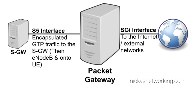
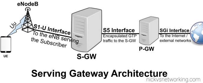
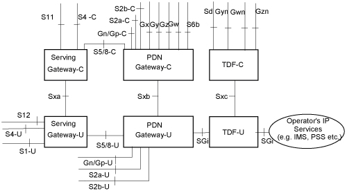
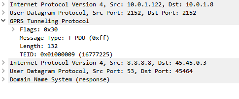
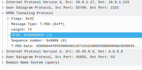
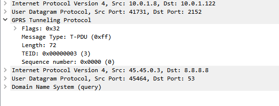
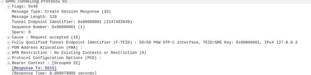
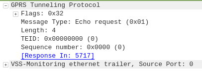
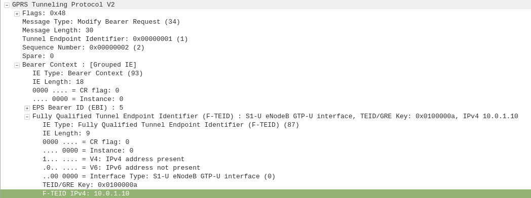
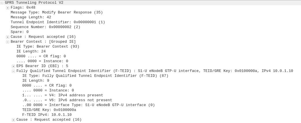
Keep in mind we’re going to be encapsulating our subscriber’s data in GTP before it’s transmitted across LTE/NR, and this means we’ll be adding:
- 8 bytes for the GTP header
- 8 bytes for the transport UDP header
- 20 bytes for the transport IPv4 header
- 14 bytes if our transport is using Ethernet
This means we’ve got 50 bytes of transmission / transport overhead. This will be important later on!
How do subscribers know what to use as MTU?
Typically when a subscriber buys a DSL service or HFC connection, they’ll either get a preconfigured router from their carrier, or they will be given a list of values to use that includes MTU.
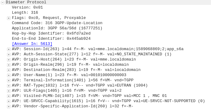
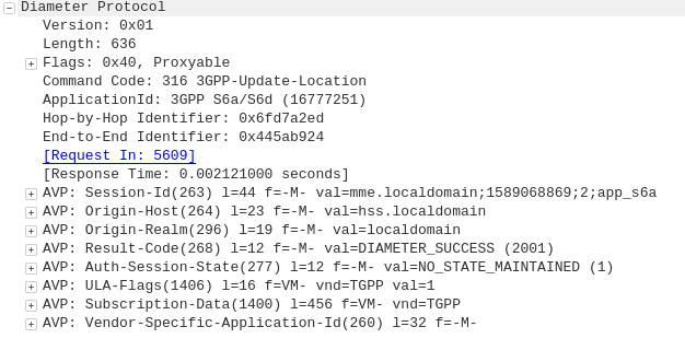
LTE and 5G on the other hand tell us the value we should use.
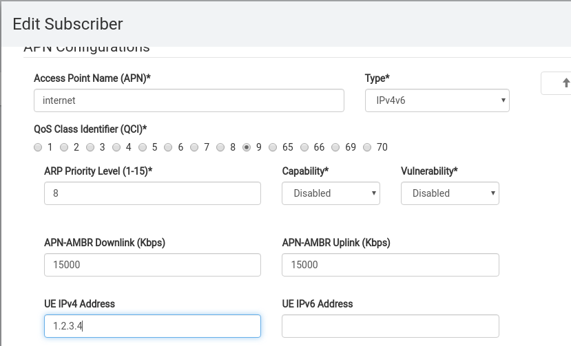
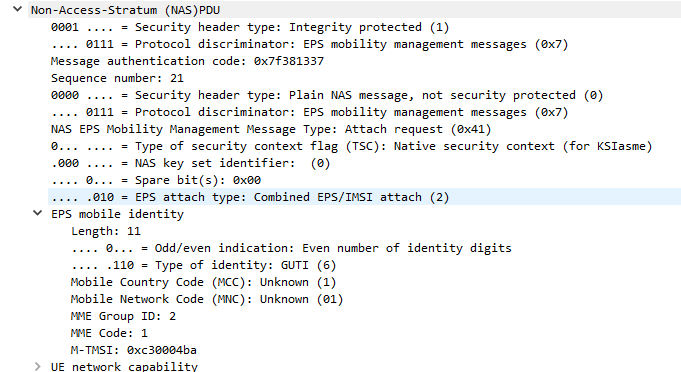
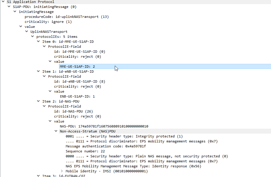
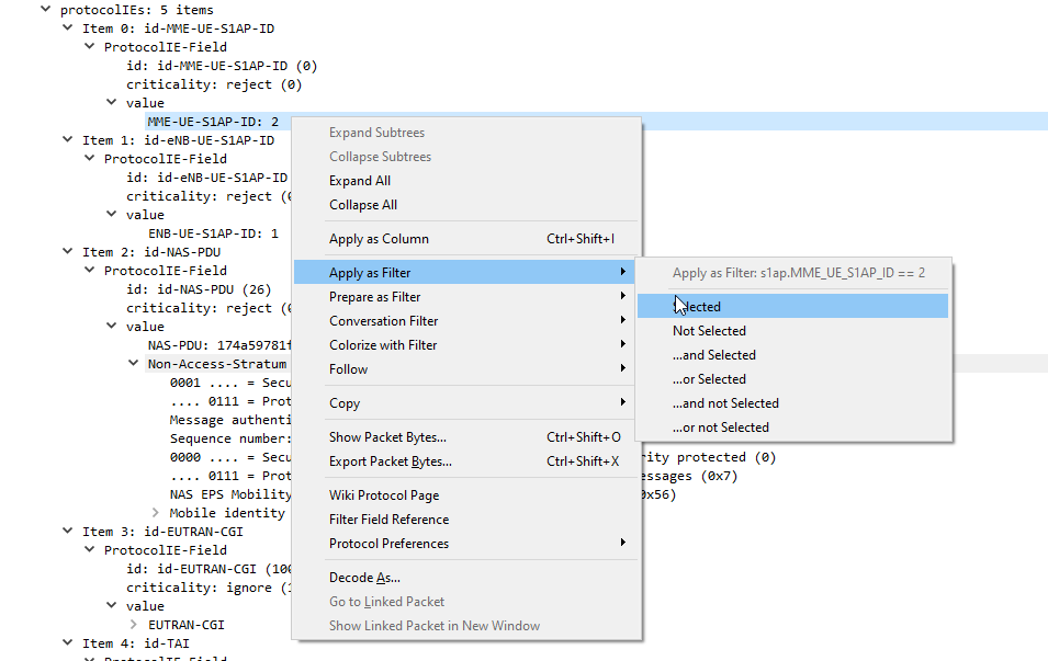
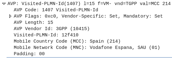
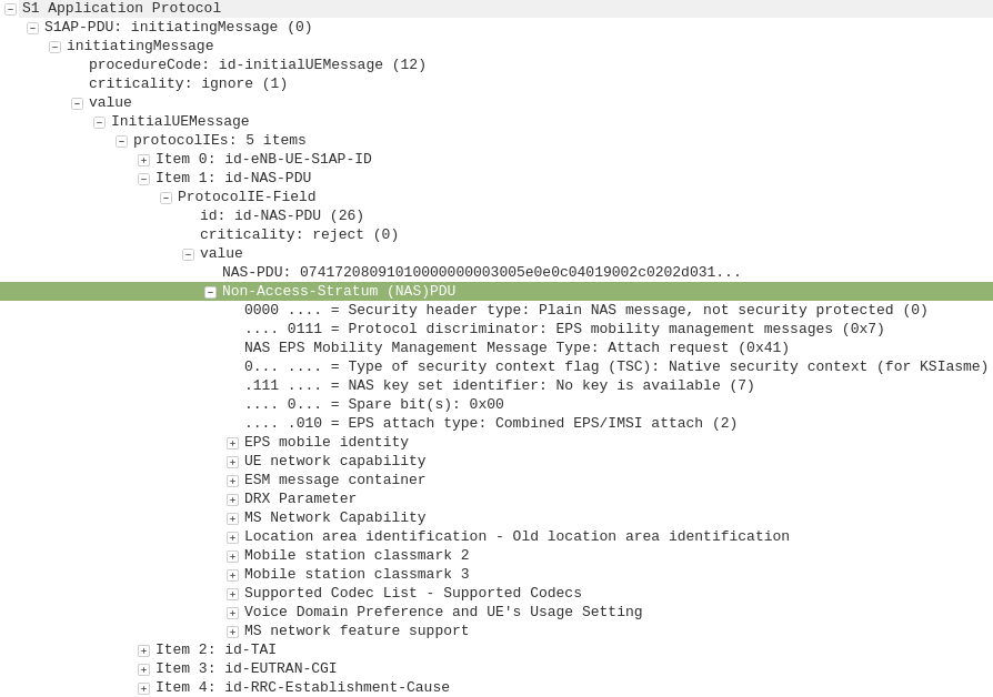
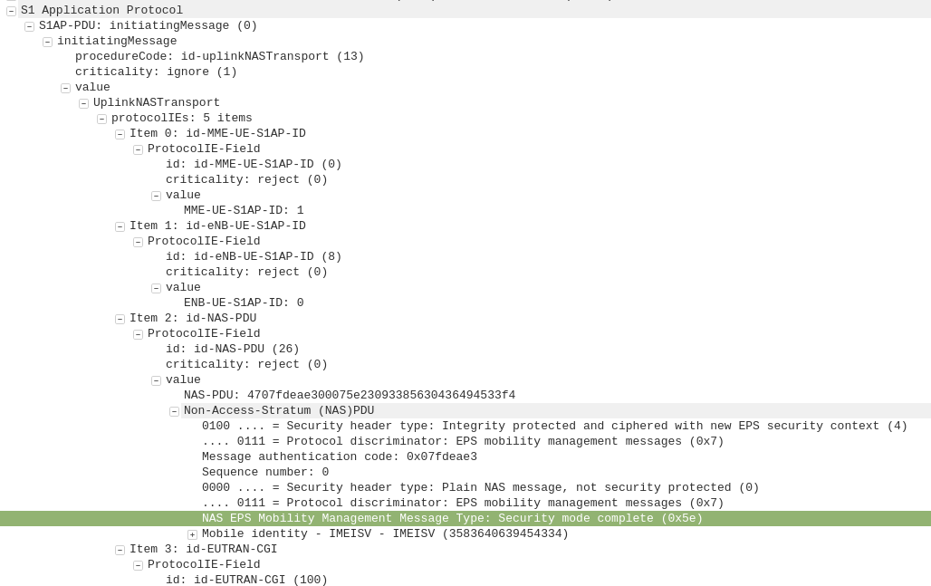
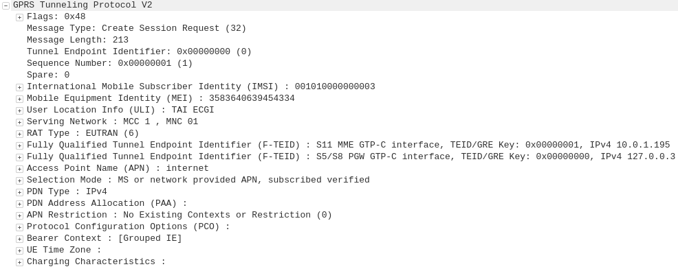
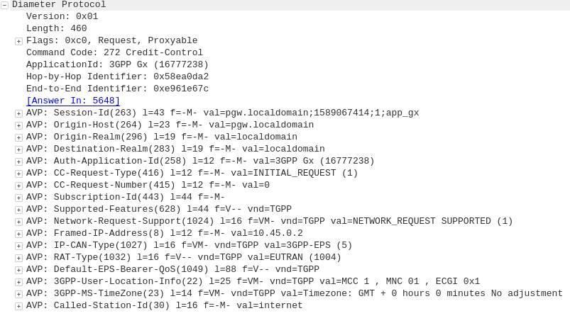
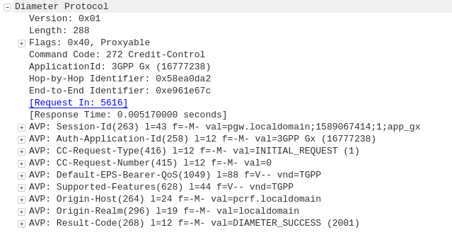
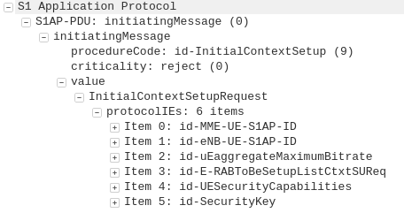
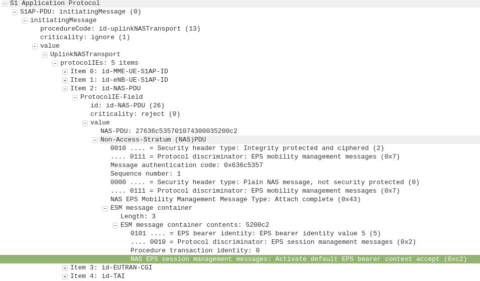
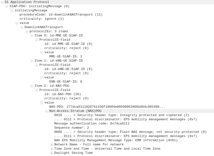
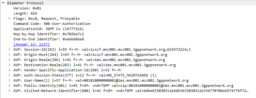
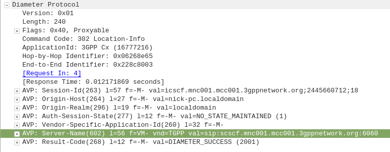
Inside the Protocol Configuration Options in the NAS PDU, the UE requests the MTU and DNS server to be used, and is provided back from the network.
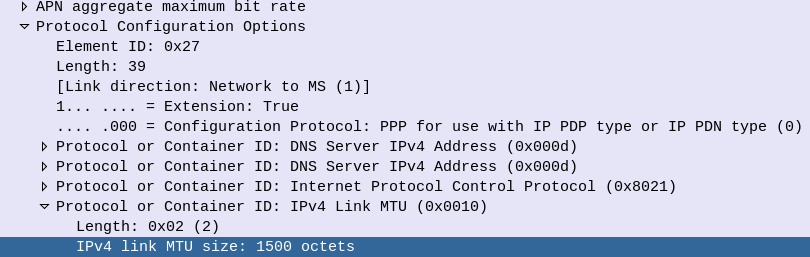
This MTU value is actually set on the MME, not the P-GW. As the MME doesn’t actually know the maximum MTU of the network, it’s up to the operator to configure this to be a value that represents the network.
Why this Matters for LTE & 5G Transmission
As we covered earlier, fragmentation is costly. If we’re fragmenting packets we are:
- Wasting resources on our transmission network / core networks – as we fragment Subscriber packets it’s taking up compute resources and therefore limiting throughput
- Wasting radio resources as additional overhead is introduced for fragmented packets, and additional RBs need to be scheduled to handle the fragmented packets
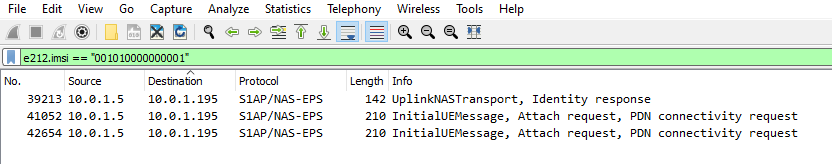
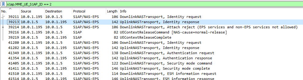
To test this I’ve setup a scenario in the lab, and we’ll look at the packet captures to see how the MTU is advertised, and see how big we can make our MTU on the subscriber side.