All the gear I’ve got so far for my DIY RAN Project requires -48vDC to power it up.
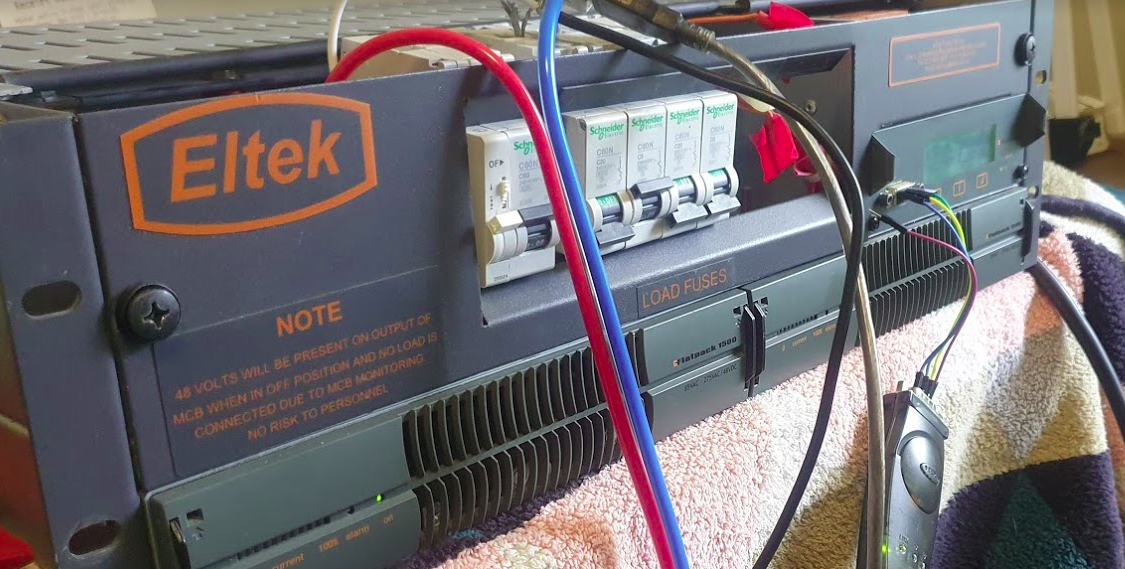
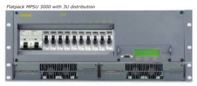
Back to online auction websites and preso I’ve ended up with an Eltek MPSU3000, from the mid 2000s.
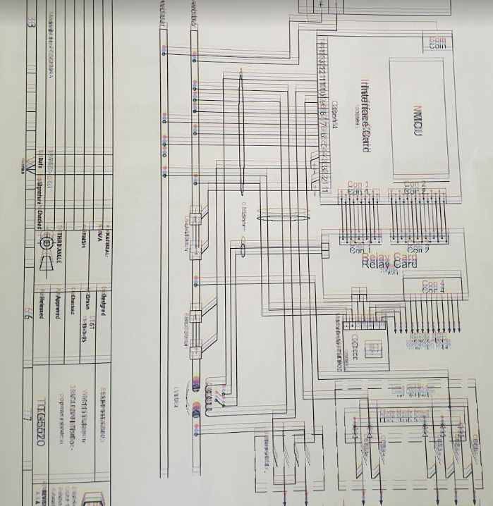
The fellow I bought it from was even nice enough to throw a binder full of printed documentation, which included a full circuit layout diagram, however this was obviously in the days of old school printers, and each of the colours were offset, providing a literal headache when reading and a bit of a reminder of what printed documents were like to deal with…
I get a headache just looking at the colours in this…
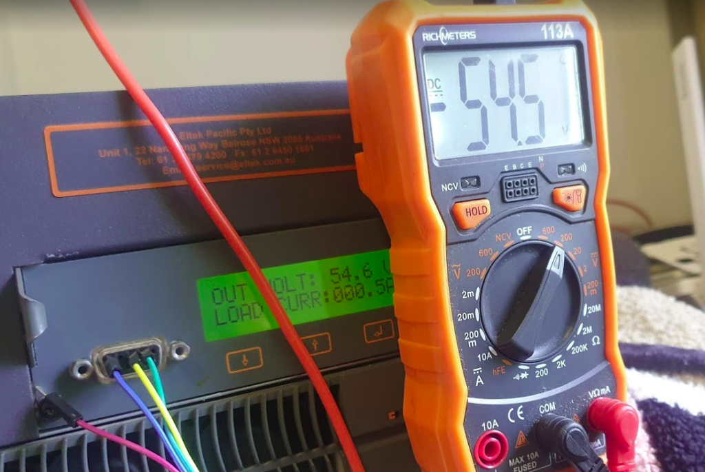
So after a bit of tinkering, wiring and reconnecting the temperature probe, I managed to fire the unit up,
While it complained about the absence of batteries (As well as rectifying AC to DC it manages and maintains banks of batteries to provide a backup power supply), it worked, and provided a very stable, clean -54v DC.
I’ve got a very old (1948) Ring Generator / Ring Machine, (same as this one) so I wired it into the rectifier and it came to life, drawing 3 amps in the process.
The Huawei gear uses proprietary power connectors, I’ve managed to start it using crocodile clips and good luck to get it powered up, but I’ve got to work out a more permanent solution before I can rack all the gear and have it setup properly.
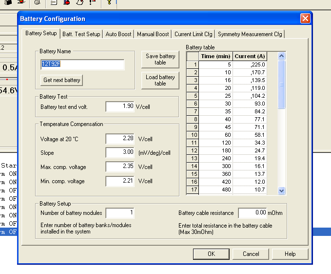
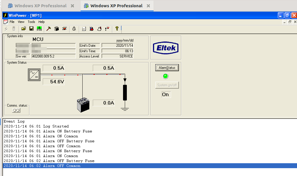
The Eltek rectifier has a number of relay contacts in the unit that can be programed to trigger in different conditions, ie mains power lost, battery fault, over temperature, etc.
These relay contacts are then wired into some sort of alarm input, to share alarm state with external monitoring equipment. (Modern rectifiers just have Ethernet and connect over TCP/IP, but this one just has a serial port and an AT command set for connecting it to a dialup modem.)
The BTS3900 has the Universal Power and Environment Unit (UPEU), which allows me to connect external alarm inputs, for things like this, water sensors, smoke detectors and intruder alarms, so hopefully I’ll get that in place when I’m further down the line.
But to program these requires the software, which I couldn’t find anywhere online. As a last ditch attempt I reached out to the manufacturer, Eltek, and asked if they’d be so kind as to send me a copy. I wasn’t expecting much, but the next day, they sent me back all the manuals and the software the next day, for a 15 year old, long surpassed product. Very impressed!
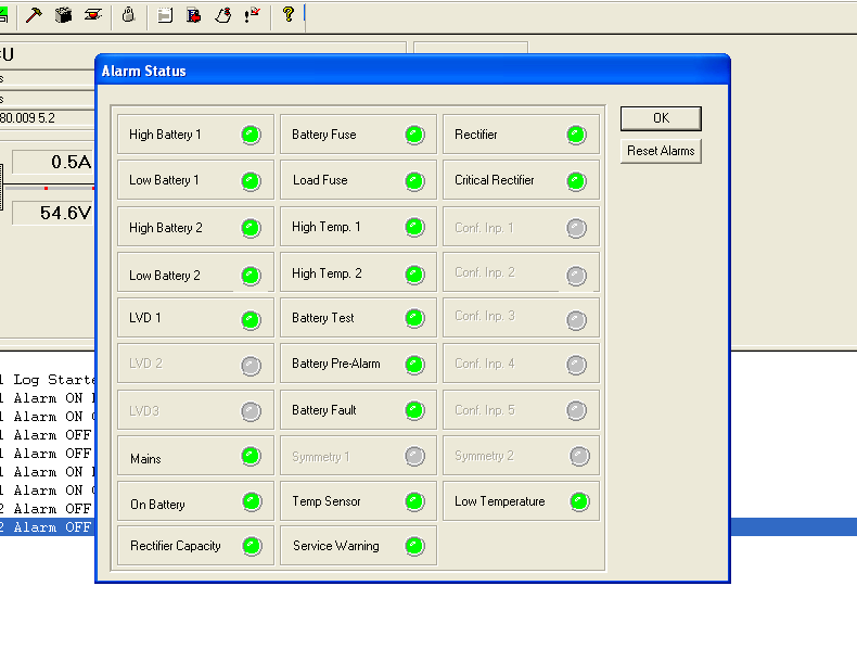
So with the aid of VMware, Windows XP, USB-Serial adapters and jumper wires, I managed to connect to the Rectifier Controller with the software and had a poke around.
Pretty impressive functionality for something this old, but no ability to monitor if MCBs have been tripped or remotely power off/on outputs.
While the unit can do some very clever things with battery management, for my lab setup I can’t see myself going to the effort of adding batteries. So for now the Rectifier’s just converting AC mains into -48vDC, but I may string some batteries in the future.
For anyone who’s ended up here looking for info on these units, or the first generation Eltek Flatpacks, I’ve attached some documentation below. The software isn’t readily available online, so I won’t post it here, but you can get it from Eltek directly.
The SUPI (Subscription Permanent Identifier) replaces the IMSI as the unique identifier for each Subscriber in 5G.
One of the issues with using IMSI in LTE/EUTRAN is there were a few occasions where the IMSI was sent over the clear – meaning the IMSIs of subscribers nearby could be revealed to anyone listening.
So what is a SUPI and what does it look like? Well, most likely it’ll look like an IMSI – 15 or 16 digits long, with the MCC/MNC as the prefix.
If you’re using a non-3GPP RAT it could be a RFC 4282 Network Access Identifier, but if it’s on a SIM card or in a Mobile Device, it’s probably exactly the same as the IMSI.
SUCI Subscription Concealed Identifier
Our SUPI is never sent over the air in the clear / plaintext, instead we rely on the SUCI (Subscription Concealed Identifier) for this, which replaces the GUTI/TMSI/IMSI for all plaintext transactions over the air.
Either the UE or the SIM generate the SUCI (if it’s done by the SIM it’s much slower), based on a set of parameters defined on the SIM.
The SUCI has to be generated by the UE or SIM in a way the Network can identify the SUPI behind the SUCI, but no one else can.
In LTE/EUTRAN this was done by the network randomly assigning a value (T-MSI / GUTI) and the network keeping track of which randomly assigned value mapped to which user, but initial attach and certain handovers revealed the real IMSI in the clear, so for 5G this isn’t an option.
So let’s take a look at how SUCI is calculated in a way that only the network can reveal the SUPI belonging to a SUCI.
The Crypto behind SUCI Calculation
As we’ll see further down, SUCI is actually made up of several values concatenated together. The most complicated of these values is the Protection Scheme Output, the cryptographically generated part of the SUCI that can be used to determine the SUPI by the network.
Currently 3GPP defines 3 “Protection Scheme Profiles” for calculating the SUCI.
Protection Scheme Identifier 1 – null-scheme
Does nothing. Doesn’t conceal the SUPI at all. If this scheme is used then the Protection Scheme Output is going to just be the SUPI, for anyone to sniff off the air.
Protection Scheme Identifier 2 & 3 – ECIES scheme profile A & B
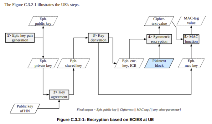
The other two Protection Scheme Identifiers both rely on Elliptic Curve Integrated Encryption Scheme (ECIES) for generation.
So if both Profile A & Profile B rely on Elliptic Curve Integrated Encryption Scheme, then what’s the difference between the two?
Well dear reader, the answer is semantics! There’s lots of parameters and variables that go into generating a resulting value from a cryptographic function, and Profile A & Profile B are just different parameters being used to generate the results.
For crypto nerds you can find the specifics in C.3.4.1 Profile A and C.3.4.1 Profile B outlined in 3GPP TS 33.501.
For non crypto nerds we just need to know this;
When the SIM is generating the SUCI the UE just asks for an identity by executing the GET IDENTITY command ADF against the SIM and uses the response as the SUCI.
When the UE is generating the SUCI, the UE gets the SUCI_Calc_Info EF contents from the SIM and extracts the Home Network Public Key from it’s reply. It uses this Home Network Public Key and a freshly created ephemeral public/private key pair to generate a SUCI value to use.
Creating the SUCI
After generating a Protection Scheme Output, we’ll need to add some extra info into it to make it useful.
The first digit of the SUCI is the SUPI type, a value of 0 denotes the value contained in the Protection Scheme Output is an IMSI, while 1 is used for Network Access Indicator for Non 3GPP access.
Next up we have the Home Network Identifier, which in a mobile environment is our PLMN (MCC/MCC).
Then a Routing Indicator, 1-4 digits long, is used with the Home Network Identifier to route the Authentication traffic to the UDM that contains that subscriber’s information, ie you may have MVNOs with their own UDM. If the routing indicator of 10 is assigned to the MVNOs SIMs then the AMF can be set to route traffic with a routing indicator of 10 to the UDM of the VMNO.
The Protection Scheme we covered earlier, with the 3 types of protection scheme (Null & two relying on Elliptic Curve Integrated Encryption Scheme).
Home Network Public Key Identifier identifies which Public Key was used to generate the Protection Scheme Output.
Finally we have the Protection Scheme Output which we covered generating in the previous session.
Usage in Signaling
The SUPI is actually rarely used beyond the initial attach to the network.
After authenticating to the network using AKA and the SUCI, in 5GC, like in LTE/EUTRAN, a shorter GUTI is used which further protects the subscriber’s identity and changes frequently.
Note: This is one part of a series of posts where I cover my adventures attempting to bring on air a commercial Macro cell site for my lab, with scrounged components.
So the Huawei BTS3900 unit I’ve ended up with, is only one part of the overall picture for building a working LTE RAN. Power systems, feeders, connectors, CPRI, antennas, baseband processing and transmission are all hurdles I’ve still got to overcome. So today, let’s talk about antennas!
For the output/TX side (downlink) of the RF Unit, I’ve ordered some 25w 50 ohm dummy loads (I’ll still need to work out how to turn down the RF power to less than 25w on the RF units). Even with the dummy load, a tiny bit of RF power is leaked, which should be enough to provide the downlink signal for my UEs – Time will tell if this works…
This option is fine for the power being pushed out of the RF unit, into the dummy load, where we have a lot of power available (too much power), but what about our very weak uplink signals from UEs?
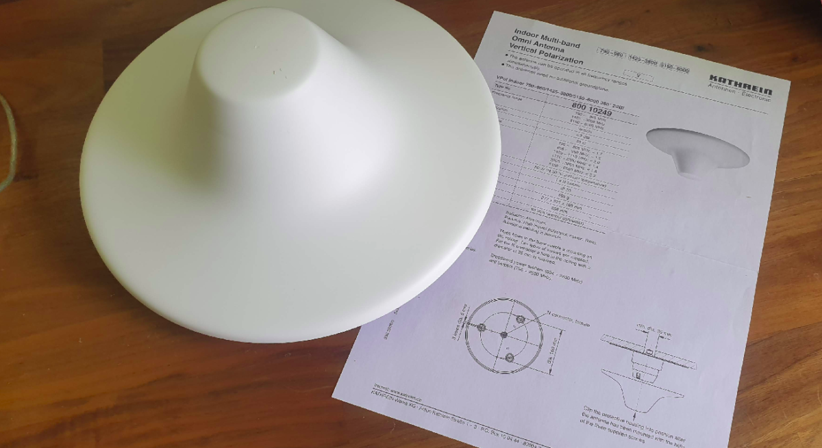
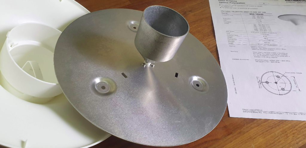
For this I’d need some decent antennas to pickup the signals from the UEs, so I ended up with some Kathrein (Now owned by Ericsson) indoor multi-band omni antennas I found on an online auction site for $10 each. (I bought 4 so I can play with MIMO.)
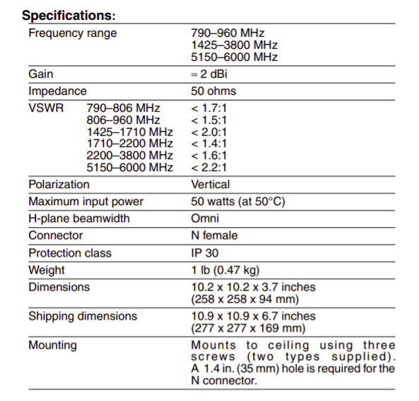
Unfortunately, the RFUs I have are Band 28 (roughly 700Mhz-750Mhz uplink and 758Mhz to 798Mhz downlink), and reading the datasheet it seems this doesn’t cover the bands I need;
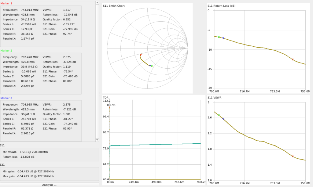
But beggars can’t be choosers, so I ran a calibration on the NanoVNA and swept the antenna from 700Mhz-750Mhz (Band 28 uplink frequencies) to see how it will perform when I get the rest of the solution together;
At the upper end of Band 28 Uplink (748Mhz) I’m getting a fairly respectable VSWR of 1.6 (Return Loss of -12.4dB), so I should be able to get away with these for what I’m doing,
I’v seen these white domes inside shopping centers and office buildings, so I was keen to crack open the case and see what magic inside, what I found was kind of underwhelming, just an aluminum plate with an aluminum reflector cone…
My ideas of putting the parts into the lathe and trying to lower it’s operating frequency by taking material off, were dashed when I realised taking material off would raise the operating frequency, not lower it…
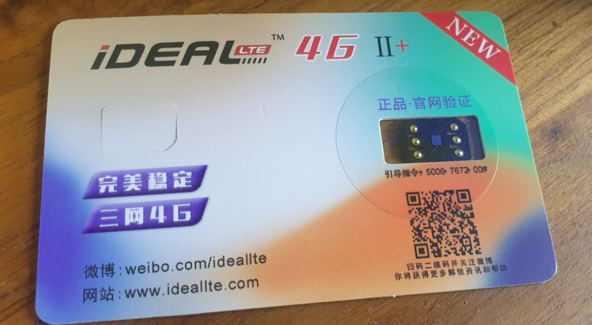
There’s a lot of “Magic Unlock SIM” products online; IdeaLTE, U-SIM LTE 4G Pro II (sic), UltraSIM, TurboSIM etc, with no real description as to what they are or how they work,
They claim to do something to do with unlocking iPhones, but with little other info.
Being interested in SIM technology, and with no real idea what they are I ordered a few.
What are they?
They’re man-in-the-middle SIM card devices that are able to intercept requests from the UE / baseband of the device.
They sit on top of the real SIM card, between it and the SIM Slot.
One of the ones I bought had a sticker on it that helped stick it into place, the other just sat above the SIM below the phone.
This means when the UE sends the APDU to request some data from the card, the SIM-shim device analyses the request, and if it matches the rules on the SIM-Shim, intercepts it and responds with something else, ignoring the data the real SIM card would send back and injecting its own,
The use for this seems to be to do with how Apple does Carrier Locking on the iPhone. It seems in the iPhone carrier settings are ranges of ICCIDs used by the different carriers for their SIMs, and uses that to identify the carrier of the SIM.
With this information it’s able to determine if the SIM card is from the carrier the iPhone is locked to or not,
Now you’re probably seeing the value in this attack – By intercepting the request for the ICCID of the card, and instead of responding with the real ICCID, the SIM-Shim intercepts the request and sending back an ICCID of a card the iPhone is carrier locked to, the iPhone is tricked into thinking it’s talking to a card from the carrier the phone is locked to.
So let’s say we’ve got an iPhone from Carrier A, and they’ve told Apple their SIM cards have ICCIDs in the range from 0001 to 0005, If I put a SIM card with the ICCID 0003 the iPhone knows it’s a SIM from Carrier A, If I put in a SIM card with ICCID 9999 the iPhone knows the SIM is not from carrier A, and therefore prevents me from using the iPhone, But if I put in one of these SIM Shims, when the iPhone ask the ICCID of the card, the SIM Shim will respond with an ICCID we set on it, so if we want to use SIM with ICCID 9999 in a phone locked to Carrier A, all we’ve got to do is setup the SIM-Shim to respond with ICCID of 0001 for example.
Phew. Ok, that’s the short run down on how it works (There’s more to activating iPhones but we’re here to talk about SIMs!).
The Hardware
So physically these are “shims” – they sit between the real SIM and the mobile phone and intercept the communications.
It blows my mind that someone’s been able to manufacture these in such a small form factor.
But there is one rather glaring flaw in having a tiny wafer that sits on top of your regular SIM, and that is if it pops up/down/ get loose and become hellish to get out.
I found their insertion and removal is a bit of a game of Russian roulette as to if it will go in, or come out, without brute force and potential damage to the device.
In the end on one iPhone I had to force the SIM tray out with a set of needle nose pliers, and my little SIM-shim was pretty beaten up and no longer useable. RIP SIM-Shim 1.
I think this may have been an early version of the same thing? Or possibly to allow dual SIM on an iPhone?
The Software
Interacting with the IdealLTE for example, is via SIM Toolkit Application for managing ICCIDs.
You can set any ICCID you want, which is cool, but limited.
Unfortunately I haven’t been able to find any way of messing with these to allow interception / replacement for other APDUs, for example if you could change the Administrative Domain to get higher access to the network.
I will at some stage put these into a SIMtrace and compare the output, and have a poke around and see if I can find anyway to change / update these, or if there’s any APDUs it responds interestingly to.
Unfortunately I’ve actually lost the new unit I had to replace the one I broke, they are very very small…
I reached out to the developer / vendor but they seem to go dark and popup under a different name, I’m not holding my breath…
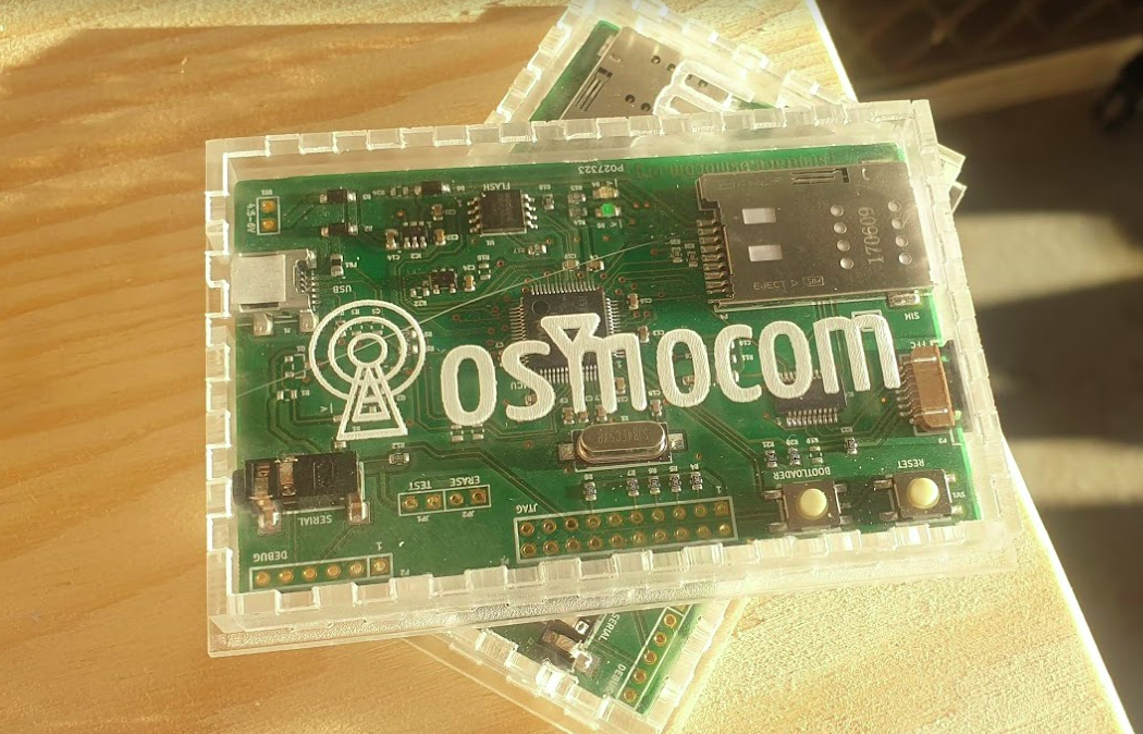
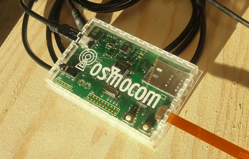
In our last Osmocom post we talked about the basics of packet data, and configuring our BTSs to support it.
In this post we’ll take a look at using Osmocom’s Serving Gateway Support Node (SGSN) named OsmoSGSN.
At the BSC traffic is divided into two categories, Circuit Switched (CS) traffic (Like voice calls & SMS) which is handed by the MSC, and Packet Switched (PS) traffic (Mobile data) is handled by the SGSN.
The SGSN acts as an anchor point for our packet data, it connects our BSC (that handles our RAN) to the GGSN (that handles the connection to external data networks).
Although it’s not technically possible to run a data only 2G/3G network (you require the MSC) it almost could be. The SGSN handles authentication of subscribers, and runs the PS network completely standalone from the CS network. The SGSN does it’s own handover management, authentication, etc, without any connection to the MSC.
Basic SGSN Config
Like the previous Osmocom network elements we’ve covered, we’ll access the SGSN via Telnet on localhost (the server running the Osmocom stack) on port 4254.
Once we’ve accessed the terminal we’ll escalate our privileges using the enable command, and run configure terminal to start configuring,
We’ll begin by setting the local IP our SGSN will listen on, the gtp local-ip, we’ll need this to be externally accessible for our BTSs, so set it to the IP of the server.
sgsn
  gtp local-ip 10.0.1.201
Next we’ll need to configure the IP of our GGSN. It gets a bit messy if we’re running everything on one box, as we’re going to have the SGSN and the GGSN trying to communicate on the same ports for GTP, so best to assign an IP in the loopback range, like 127.0.0.2 in my case, for the GGSN:
We can also steer GGSN selection based on the APN, for example an APN for a corporate network, you may want to have a dedicated GGSN for, for example, we could create a second GGSN – GGSN 1 and route any traffic on our “special.access.net” APN to that GGSN, and everything else to GGSN0:
You may notice that APNs look like domain names – that’s because they can be,
If we owned the domain special.access.net we could set it to resolve to the GGSN IP we’re using for the special.access.net GGSN at 10.0.1.99, and instead of hardcoding the IP in our config use a DNS server (like 8.8.8.8) to resolve these.
To learn more about setting up compression and encryption of the data, take a look in the Osmo-SGSN Manual.
Charging
Charging in mobile networks is a topic we could spend weeks on, but we’re not going to!
OsmoSGSN implements a simple CDR based charging mechanism that writes to a text file a simple CSV file with most importantly the IMSI and bytes in / out for each subscriber, that can be used to implement offline charging (Post paid) if required, and with some hacky scripts can even cut off sessions after reaching a certain amount of throughput (online charging aka pre-paid).
By adding the below to our config OsmoSGSN will write CDRs into /home/nick/sgsn.cdr every 60 seconds.
Note: As this space develops so quickly I’ve refreshed the original post from November 2021 in March 2021 with updated instructions.
While 5G SA devices are still in their early stages, and 5G RAN hardware / gNodeBs are hard to come by, so today we’ll cover using UERANSIM to simulate UEs and 5G RAN, to put test calls through our 5GC.
Bringing your 5G Core Online
We’ll use Open5Gs for all the 5GC components, and install on any recent Ubuntu distribution.
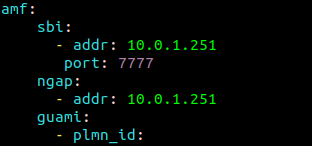
The first point of contact we’ll need to talk about is the AMF,
The AMF – the Access and Mobility Function is reached by the gNodeB over the N2 interface. The AMF handles our 5G NAS messaging, which is the messaging used by the UEs / Devices to request data services, manage handovers between gNodeBs when moving around the network, and authenticate to the network.
By default the AMF binds to a loopback IP, which is fine if everything is running on the same box, but becomes an issue for real gNodeBs or if we’re running UERANSIM on a different machine.
This means we’ll need to configure our AMF to bind to the IP of the machine it’s running on, by configuring the AMF in /etc/open5gs/amf.yaml, so we’ll change the ngap addr to bind the AMF to the machine’s IP, for me this is 10.0.1.207,
ngap:
  - addr: 10.0.1.207
In the amf.conf there’s a number of things we can change and configure; such as the PLMN and network name, the NRF parameters, however for now we’ll keep it simple and leave everything else as default.
To allow the changes to take effect, we’ll restart the Open5GS AMF service to make our changes take effect;
$ sudo systemcl restart open5gs-amfd
Setting up the Simulator
We’re using UERANSIM as our UE & RAN Simulator, so we’ll need to get it installed. I’m doing this on an Ubuntu system as we’re using Snaps.
Once we’ve got the software installed we’ll need to put together the basic settings.
You should see these files in the /build/ directory and they should be executable.
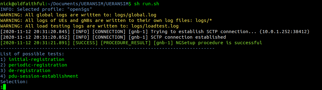
Running the Simulator (UERANSIM)
UERANSIM has two key parts, like any RAN,
The first is the gNodeB, that connects to our AMF and handles subscriber traffic over our (simulated) radio link,
The other is our subscribers themselves – the UEs.
Both are defined and setup through config files in the config/ directory,
Configuring & Starting the gNodeB
While we’re not actually going to bring anything “on air” in the RF sense, we’ll still need to configure and start our gNodeB.
All the parameters for our gNodeB are set in the config/open5gs-gnb.yaml file,
Inside here we’ll need to set the the parameters of our simulated gNodeB, for us this means (unless you’ve changed the PLMN etc) just changing the Link IPs that the gNodeB binds to, and the IP of the AMFs (for me it’s 10.0.1.207) – you’ll need to substitute these IPs with your own of course.
Now we should be able to start the gNodeB service and see the connection, let’s take a look,
We’ll start the gNodeB service from the UERANSIM directory by running the nr-gnb service with the config file we just configured in config/open5gs-gnb.yaml
$ build/nr-gnb -c config/open5gs-gnb.yaml
All going well you’ll see something like:
[2021-03-08 12:33:46.433] [ngap] [info] NG Setup procedure is successful
And if you’re running Wireshark you should see the NG-AP (N2) traffic as well;
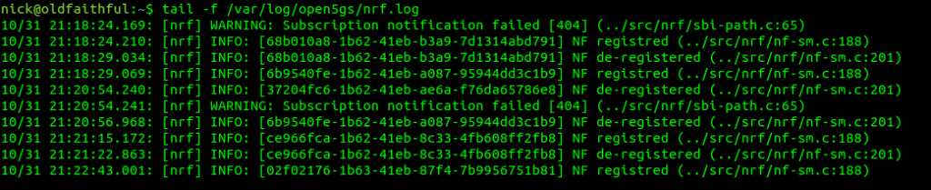
If we tail the logs on the Open5GS AMF we should also see the connection too:
Configuring the UE Simulator
So with our gNodeB “On the air” next up we’ll connect a simulated UE to our simulated gNodeB.
We’ll leave the nr-gnb service running and open up a new terminal to start the UE with:
$ build/nr-gnb -c config/open5gs-gnb.yaml
But if you run it now, you’ll just see errors regarding the PLMN search failing,
So why is this? We need to tell our UE the IP of the gNodeB (In reality the UE would scan the bands to find a gNB to serve it, but we’re simulating hre).
So let’s correct this by updating the config file to point to the IP of our gNodeB, and trying again,
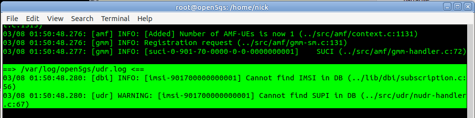
So better but not working, we see the RRC was released with error “FIVEG_SERVICES_NOT_ALLOWED”, so why is this?
A quick look at the logs on Open5Gs provides the answer,
Of course, we haven’t configured the subscriber in Open5Gs’s UDM/UDR.
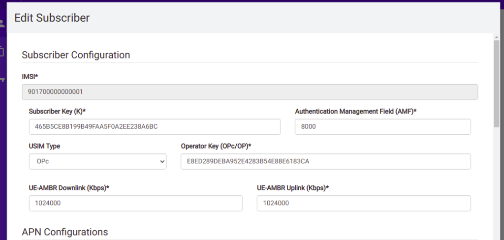
So we’ll browse to the web interface for Open5GS HSS/UDR and add a subscriber,
We’ll enter the IMSI, K key and OP key (make sure you’ve selected OPc and not OP), and save. You may notice the values match the defaults in the Open5GS Web UI, just without the spaces.
Running the UE Simulator
So now we’ve got all this configured we can run the UE simulator again, this time as Sudo, and we should get a very different ouput;
$ build/nr-gnb -c config/open5gs-gnb.yaml
Now when we run it we should see the session come up, and a new NIC is present on the machine, uesimtun0,
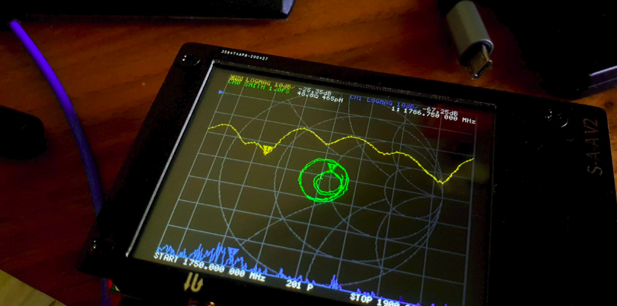
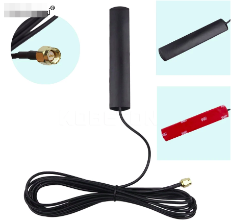
These antennas claimed to operate on 900/1800/2100MHz and this time had the correct connector (SMA not RP-SMA)…
I ordered two of these antennas for the princely sum of $3 and hooked them onto the NanoVNA to analyse the antennas – the poor man’s Anritsu SiteMaster!
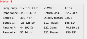
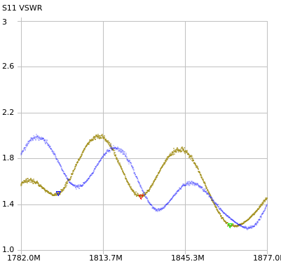
I was operating the GSM network using ARFCN 871 with the SDR which translates to 1782 MHz for Uplink and 1877 MHz for Downlink, so I plugged in the values into the VNA to take a look at how it performs in those ranges,
Performance is actually pretty on point,
On the Uplink frequency we’ve got a VSWR of 1.15 which is about as good as it gets,
And in the downlink we’ve got a VSWR of 1.221, still pretty good.
Performance on the remainder of the 1800MHz band is pretty decent, with clear drops in VSWR where the Uplink and Downlink channels lie.
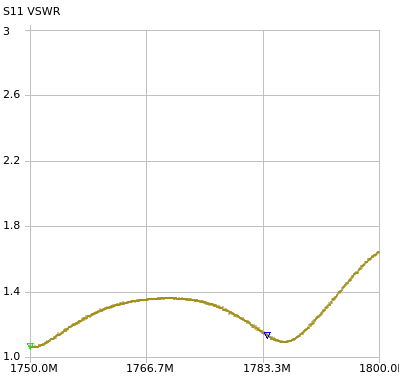
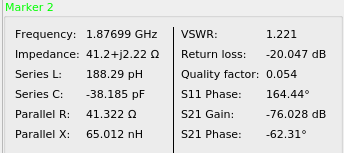
I measured the full band for Uplink on the 1800Mhz band (1710Mhz – 1785Mhz):
Analysis of Uplink Bands
Which shows not all channels are created equal, if you were looking for real performance on these antennas and not just playing, you’d probably want to put your uplink channel on one of the frequencies shown by the marker,
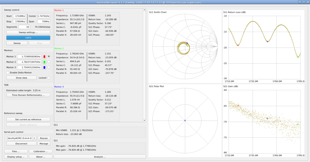
And the full band for Downlink on the 1800Mhz band (1805Mhz – 1890Mhz):
Again, varied performance, but the peaks and troughs line up on the uplink and downlink, so a lower ARFCN in the 1800Mhz band would put you about on the red marker for both,
Comparing the output of each of the antennas I’ve got
In reality I could be using a bent coat hanger for an antenna, the signals shouldn’t be able to leave the room, but it’s a good excuse to use the toys!
Next up we’ll need to configure the NRF on the domain “nrf.5gc.mnc001.mcc001.3gppnetwork.org”, for this we’ll edit /etc/open5gs/nrf.conf and set the binding IP.
nrf:
  sbi:
    - addr:
       - 10.0.1.252
      port: 7777
Now for each Network Element we’re bringing online we’ll need to point it at our NRF’s address (or IP).
Mobile networks are designed to be redundant and resilient, with N+1 for everything.
Every network element connects to multiple other network elements.
The idea being the network is architected so a failure of any one network element will not impact service.
To take an LTE/EPC example, your eNodeBs connect to multiple MMEs, which in turn connect to multiple HSSs, multiple S-GWs, multiple EIRs, etc. The problem is when each eNodeB connects to 3 MMEs, and you want to add a 4th MME, you have to go and reconfigure all the eNodeBs to point to the new MME, and all the HSSs to accept that MME as a new Diameter Peer, for example.
The more redundant you make the network, the harder it becomes to change.
This led to development of network elements like Diameter Routing Agents (DRAs) and DNS SRV for service discovery, but ultimately adding and removing network elements in previous generations of mobile core, involved changing a lot of config on a lot of different boxes.
The Solution
The NRF – Network Repository Function serves as a central repository for Network Functions (NFs) on the network.
In practice this means when you bring a new Network Function / Network Element online, you only need to point it at the NRF, which will tell it about other Network Functions on the network, register the new Network Function and let every other interested Network Function know about the new guy.
Take for example adding a new AMF to the network, after bringing it online the only bit of information the AMF really needs to start placing itself in the network, is the details of the NRF, so it can find everything it needs to know.
Our new AMF will register itself to the NRF, advertising what Network Functions it can offer (ie AMF service), and it’ll in turn be able to learn about what Network Functions it can consume – for example our AMF would need to know about the UDMs it can query data from.
It is one of the really cool design patterns usually seen in modern software, that 3GPP have adopted as part of the 5GC.
In Practice
Let’s go into a bit more detail and look at how it looks.
The NRF uses HTTP and JSON to communicate (anything not using ASN.1 is a winner), and looks familiar to anyone used to dealing with RESTful APIs.
Let’s take a look at how an AMF looks when registering to a NRF,
NF Register – Providing the NRF a profile for each NF
In order for the NRF to function it has to know about the presence of all the Network Functions on the network, and what they support. So when a new Network Function comes online, it’s got to introduce itself to the NRF.
It does this by providing a “Profile” containing information about the Network Functions it supports, IP Addresses, versions, etc.
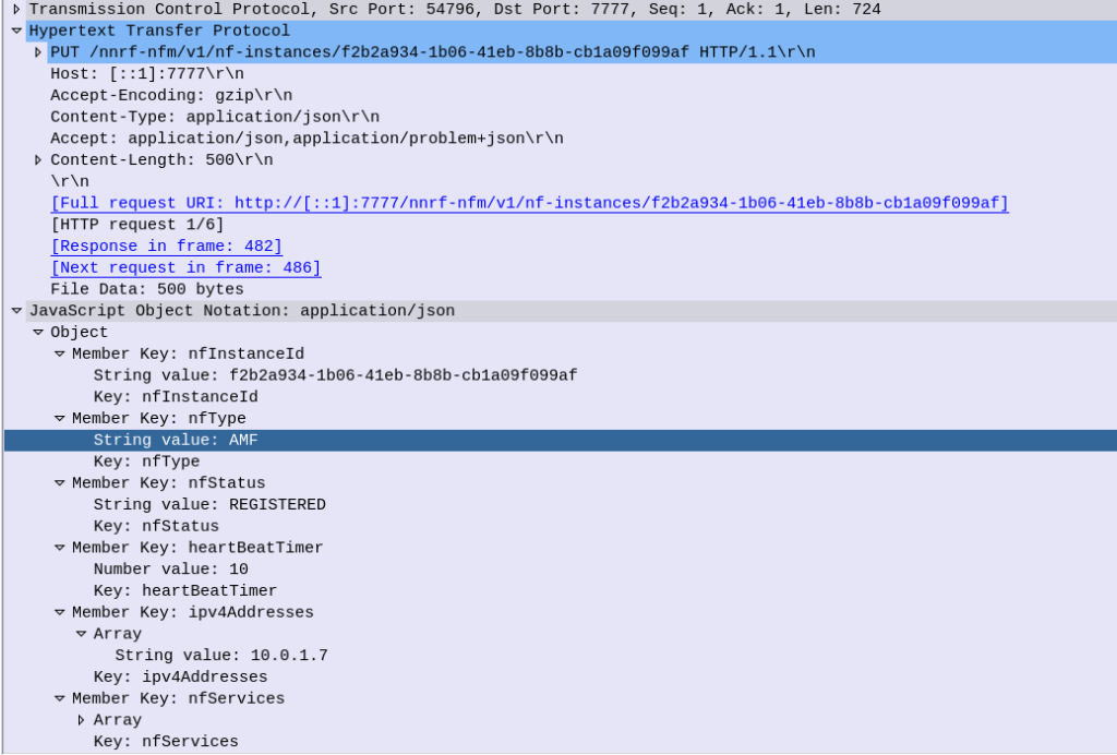
Going back to our AMF example, the AMF sends a HTTP PUT request to our NRF, with a JSON payload describing the functions and capabilities of the AMF, so other Network Functions will be able to find it.
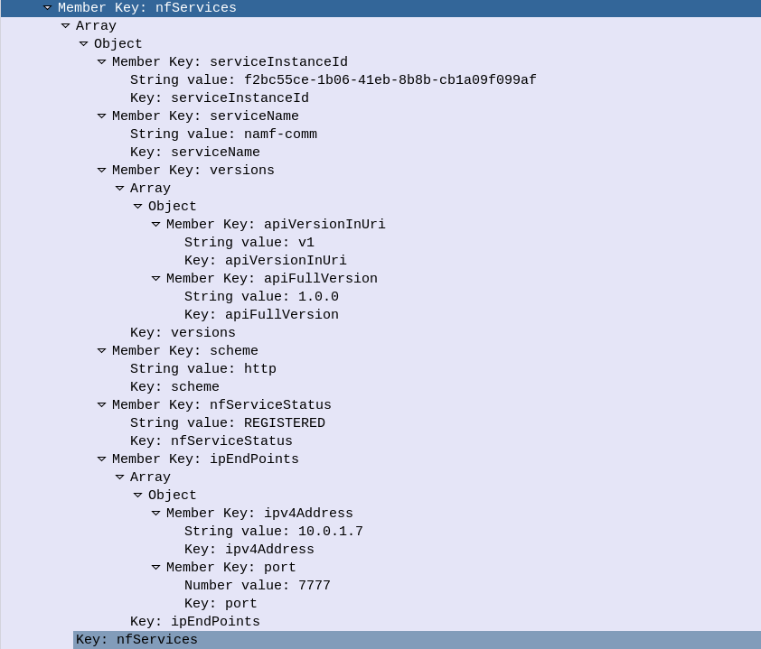
Let’s take a look at what’s in the JSON payload used for the NF Profile.
Each Network Function is identified by a UUID – nfInstanceId, in this example it’s value is “f2b2a934-1b06-41eb-8b8b-cb1a09f099af”
The nfType (Network Function type) is an AMF, and it’s IP Address is 10.0.1.7
The heartBeatTimer sets how often the network function (in this case AMF) sends messages to the NRF to indicate it’s still alive. This prevents a device registering to an NRF and then going offline, and the NRF not knowing.
The nfServices key contains an array of services and details of those services, in the below example the key feature is the serviceName which is namf-comm which means the Namf_Communication Service offered by the AMF.
The NRF files this info away for anyone who requests it (more on that later) and in response to this our NRF will indicate (hopefully) that it’s successfully created the entry in its internal database of Network Functions for our AMF, resulting in a HTTP 201 “Created” response back from the NRF to the AMF.
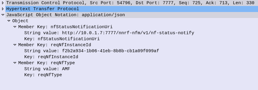
NRF StatusSubscribe – Subscribe & Notify
Simply telling the NRF about the presence of NFs is one thing, but it’s not much use if nothing is done with that data.
A Network Function can subscribe to the NRF to get updates when certain types of NFs enter/leave the network.
Subscribing is done by sending a HTTP POST with a JSON payload indicating which NFs we’re interested in.
Contents of a Subscription message to be notified of all AMFs joining the network
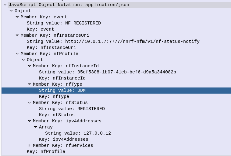
Whenever a Network Function registers on the NRF that related to the type that has been subscribed to, a HTTP POST is sent to each subscriber to let them know.
For example when a UDM registers to the network, our AMF gets a Notification with information about the UDM that’s just joined.
NRF Update – Updating NRF Profiles & Heartbeat
If our AMF wants to update its profile in the NRF – for example a new IP is added to our AMF, a HTTP PATCH request is sent with a JSON payload with the updated details, to the NRF.
The same mechanism is used as the Heartbeat / keepalive mechanism, to indicate the NRF is still there and working.
Summary
The NRF acts as a central repository used for discovery of neighboring network functions.
Meta: The Australian government made up it’s mind some time ago that Huawei would be blacklisted from providing equipment for 5G networks. Several other countries have adopted the same policy in regards, and as such, deployed Huawei tech is being replaced, and some of it filters down to online auction sites…
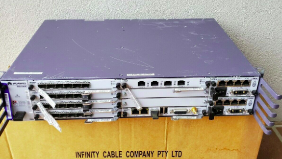
So I kind of purchased an item described as “Huawei BBU3900” with a handful of unknown cards and 2 LRFU units, for just over $100.
My current lab setup is a single commercial picocell and a draw of SDR hardware that works with mixed results, so the idea of having a commercial macro cell to play with seemed like a great idea, I put lowball offer in and the seller accepted.
Now would be a good time to point out I don’t know much about RAN and it’s been a long time since I’ve been working on power systems, so this is shaping up to be a fun project.
Photo from the listing
Photo from the listing
I did a Huawei RAN course years ago and remembered the rough ingredients required for LTE:
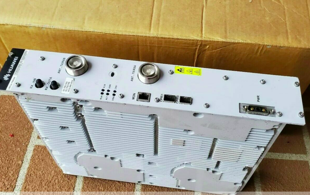
You needed either RRUs (Remote Radio Units) or RFUs (Radio Frequency Units) to handle the RF side of things. RRUs are designed for outdoor use (such as mounting on the tower) and RFUs are designed for indoor use, like mounting in a cabinet. I’ve ended up with two LRFUe units, which I can join together for 2x MIMO, operate on Band 28 and can put out a whopping 80W of transmit power, yes I’m going to need some big attenuators…
You need a Baseband Processor card to tell the Radio units what do do. The card connects the CPRIs (Typically optic fiber links) between the radio units and the baseband. The chassis I purchased came with a stack of WBBP (For WCDMA) cards and a single LBBP card for LTE. The LBBP card has 6 SFP ports for the CPRI interfaces, which is more than enough for my little lab. (You can also daisy-chain CPRIs so I’m not even limited to 6 Radio Units.)
You need a backplane and a place for the cards to live – this is the BBU3900 chassis. It’s got basic switching to allow communication between cards, a chassis to distribute power and cooling. (Unlike the Ericson units there is actually a backplane for communications in the Huawei chassis – the Ericsson RBS series has is just power and cooling in the chassis)
Optional – Dedicated transmission card, I’ve ended up with a Universal Transmission Processor (UTRP9) with 2x Gig Ethernet and 2x Fast Ethernet ports for transmission. This will only work for GSM and UMTS though, not LTE, so not much use for me.
You need something to handle main processing (LTE / Universal Main Processing and Transmission Unit (LMPT / UMPT)). Unfortunately the unit I’ve ended up with only came with a WMPT (For WCDMA), so back online to find either an LMPT (LTE) or UMPT (Universal (2G/3G/4G))…
You need a Universal Power and Environment Module (UPEU) to power up the chassis and handle external IO for things like temperature alarms, door sensors and fire detectors. This chassis has two for redundancy / extra IO & extra power capacity.
So in order to get this running I still need quite a few components:
Attenuators – I’ll be able to turn the power down, sure, but not to the levels required to be legal.
Antennas – These are FDD units, so I’ll need two antennas for each RFU, on Band 28
Feeder Cables – To connect the antennas
SMF cables and SFPs – I’ve got a pile in my toolbox, but I’ll need to work out what’s supported by these units
A big -48vDC rectifier (I got the BBU3900 unit powered up with an existing supply I had, but I’m going to need something bigger for the power hungry RFUs)
DC Distribution Unit – Something to split the DC between the RFUs and the BBU, and protect against overload / short
USB-Network adapter – For OAM access to the unit – Found these cheaply online and got one on the way
The LTE Main Processing & Transmission (LMPT) card – Ordered a second hand one from another seller
I powered up the BTA3900 and sniffed the traffic, and can see it trying to reach an RNC.
Unfortunately with no open source RNC options I won’t be posting much on the topic of UMTS or getting the UMTS/WCDMA side of things on the air anytime soon…
So that’s the start of the adventure.
I don’t know if I’ll get this all working, but I’m learning a lot in the process, and that’s all that really matters…
As the standardisation for 5G-SA has been completed and the first roll outs are happening, I thought I’d cover the basic architecture of the 5G Core Network, for people with a background in EPC/SAE networks for 4G/LTE, covering the key differences, what’s the same and what’s new.
The AMF – Authentication & Mobility Function, serves much the same role as the MME in LTE/EPC/SAE networks.
Like the MME, the AMF only handles Control Plane traffic, and serves as the gatekeeper to the services on the network, connecting the RAN to the core, authenticating subscribers and starting data / PDN connections for the UEs.
While the MME connects to eNodeBs for RAN connectivity, the AMF connects to gNodeBs for RAN.
The Authentication Functions
In EPC the HSS had two functions; it was a database of all subscribers’ profile information and also the authentication centre for generating authentication vectors.
5GC splits this back into two network elements (Akin to the AuC and HLR in 2G/3G).
The UDM (Unified Data Management) provides the AMF with the subscriber profile information (allowed / barred services / networks, etc),
The AUSF (Authentication Server Function) provides the AMF with the authentication vectors for authenticating subscribers.
Like in UMTS/LTE USIMs are used to authenticate subscribers when connecting to the network, again using AKA (Authentication and Key Agreement) for mutual subscriber & network authentication.
Other authentication methods may be implemented, R16 defines 3 suporrted methods, 5G-AKA, EAP-AKA’, and EAP-TLS.
This opens the door for the 5GC to be used for non-mobile usage. There has been early talk of using the 5G architecture for fixed line connectivity as well as mobile, hence supporting a variety of authentication methods beyond classic AKA & USIMs. (For more info about Non-3GPP Access interworking look into the N3IWF)
The Mobility Functions
When a user connects to the network the AMF selects a SMF (Session Management Function) akin to a P-GW-C in EPC CUPS architecture and requests the SMF setup a connection for the UE.
This is similar to the S11 interface in EPC, however there is no S-GW used in 5GC, so would be more like if S11 were instead sent to the P-GW-C.
The SMF selects a UPF (Akin to the P-GW-C selecting a P-GW-U in EPC), which will handle this user’s traffic, as the UPF bridges external data networks (DNs) to the gNodeB serving the UE.
Moving between cells / gNodeBs is handled in much the same way as done previously, with the path the UPF sends traffic to (N3 interface) updated to point to the IP of the new gNodeB.
When a UE attempts to connect to the network their signalling traffic (Using the N1 reference point between the UE and the AMF), is sent to the AMF.
an authentication challenge is issued as in previous generations.
Upon successful authentication the AMF signals the SMF to setup a session for the UE. The SMF selects a UPF to handle the user plane forwarding to the gNodeB serving the UE.
Key Differences
Functions handled by the MME in EPC now handled by AMF in 5GC
Functions of HSS now in two Network Functions – The UDM (Unified Data Management) and AUSF (Authentication Server Function)
Setting up data connections “flatter” (more info on the User Plane differences can be found here)
Non 3GPP access (Potentially used for fixed-line / non mobile networks)
As the standardisation for 5G-SA has been completed and the first roll outs are happening, I thought I’d cover the basic architecture of the 5G Core Network, for people with a background in EPC/SAE networks for 4G/LTE, covering the key differences, what’s the same and what’s new.
The idea behind this, is that by removing the S-GW removes extra hops / latency in the network, and allows users to be connected to the best UPF for their needs, typically one located close to the user.
However, there are often scenarios where an intermediate function is required – for example wanting to anchor a session to keep an IP Address allocated to one UPF associated with a user, while they move around the network. In this scenario a UPF can act as an “Session Anchor” (Akin to a P-GW), and pass through “Intermediate UPFs” (Like S-GWs).
Unlike the EPCs architecture, there is no limit to how many I-UPFs can be chained together between the Session Anchoring UPF and the gNB, and this chaining of UPFs allows for some funky routing options.
The UPF is dumb by design. The primary purpose is just to encapsulate traffic destined from external networks to subscribers into GTP-U packets and forward them onto the gNodeB serving that subscriber, and the same in reverse. Do one thing and do it well.
SMF – Session Management Function
So with dumb UPFs we need something smarter to tell them what to do.
Control of the UPFs is handled by the SMF – Session Management Function, which signals using PFCP down to the UPFs to tell them what to do in terms of setting up connections.
This means the interface between the SMF and UPF (the N4 interface) is more or less the same as the interface between a P-GW-C and a P-GW-U seen in CUPS.
When a subscriber connects to the network and has been authenticated, the AMF (For more info on the AMF see the sister post to this topic covering Control Plane traffic) requests the SMF to setup a connection for the subscriber.
Interworking with EPC
For deployments with an EPC and 5GC interworking between the two is of course required.
The P-GW-C and P-GW-U communications using PFCP are essentially the same as the N4 interface (between the SMF and the UPF) so the P-GW-U is able to act as a UPF.
This means handovers between the two RATs / Cores is seamless as when moving from an LTE RAT and EPC to a 5G RAT and 5G Core, the same UPF/P-GW-U is used, and only the Control Plane signalling around it changes.
When moving from LTE to 5G RAT, the P-GW-C is replaced by the SMF, When moving from 5G RAT to LTE, the SMF is replaced by the P-GW-C. In both scenarios user plane traffic takes the same exit point to external Data Networks (SGi interface in EPC / N6 interface in 5GC).
Interfaces / Reference Points
N3 Interface
N3 interface connects the gNodeB user plane to the UPF, to transport GTP-U packets.
This is a User Plane interface, and only transports user plane traffic.
This is akin to the S1-UP interface in EPC.
N4 Interface
N4 interface connects the Session Management Function (SMF) control plane to the UPF, to setup, modify and delete UPF sessions.
It is a control plane interface, and does not transport User Plane traffic.
This interface relies on PFCP – Packet Forwarding Control Protocol.
This is akin to the SxB interface in EPC with CUPS.
N6 Interface
N6 interface connects the UPF to External Data Networks (DNs), taking packets destined for Subscribers and encapsulating them into GTP-U packets.
This is a User Plane interface, and only transports user plane traffic.
This is akin to the SGi interface in EPC.
N9 Interface
When Session Anchoring is used, and Intermediate-UPFs are used, the connection between these UPFs uses the N9 interface.
This is only used in certain scenarios – the preference is generally to avoid unnecessary hops, so Intermediate-UPF usage is to be avoided where possible.
As this is a User Plane interface, it only transports user plane traffic.
When used this would be akin to the S5 interface in EPC.
N11 Interface
SMFs need to be told when to setup / tear down connections, this information comes from the AMF via the N11 interface.
As this is a Control Plane interface, it only transports control plane traffic.
This is similar to the S11 interface between the MME and the S-GW in EPC, however it would be more like the S11 if the S11 terminated on the P-GW.
I had a discussion with a friend the other day about if hold is signified with a=sendonly or a=recvonly, which led me to revisiting the RFC to confirm, so here’s an overview of how “Call Hold” works in SIP.
By the Book
According to RFC 6337 a user can hold calls by sending a new SDP offer in an established session (Re-INVITE on active call), with an SDP payload of a=sendonly for each media stream the user want’s to hold.
The SIP Switch / PBX / UAS replies with an updated SDP where each media stream’s SDP contains a=recvonly.
So it’s both, depending on which leg you’re looking at.
In Common Practice
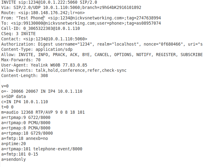
When a UAC puts a call in hold, it does so by sending a SIP re-INVITE, updating the SDP to include the attribute line “sendonly”
See the bottom line of the SDP is a=sendonly ? That’s denoting the call is to be put on hold,
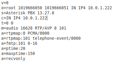
If the call hold was sucesful the UAS sends back a 200 Ok, with the SDP attribute set to recvonly
The a=recvonly denotes the call has been held.
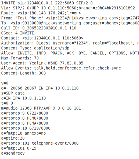
To retrieve the call another SIP re-invite is sent by the UAC, this time setting the media attribute back to sendrecv
If sucesful a 200 OK is sent by the UAS with the a=sendrecv also set.
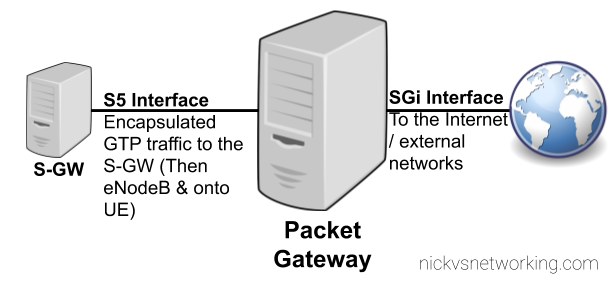
The Packet Gateway connects users of an LTE network to external networks like the Internet, by encapsulating IP packets inside GTP and forwarding them on to reach our subscriber wherever in the network they are.
So we use GTP to encapsulate user’s traffic, making it easy to carry it transparently from outside networks (Like the Internet) to the eNodeB and onto our UE / mobile phones, and more importantly redirect where the user’s traffic it’s going while keeping the same IP address.
But we need a network element to take plain old IP from external networks / Internet, and encapsulate the traffic into the GTP packets we’ll send to the subscriber.
This network element will have to do the same in reverse and decapsulate traffic coming from the subscriber to put it back onto the external networks / Internet.
That’s the role of the Packet Gateway (P-GW). The P-GW sits on the border between the outside network (An interface / reference point known as the SGi Interface) and the rest of the packet core (Serving-Gateway then onto eNodeB & UE) via the S5 Interface.
Let’s look at how the P-GW handles an incoming packet:
An IP packet comes in from the Internet destined for IP 1.2.3.4 and routed to the P-GW.
The P-GW looks up in it’s internal database what Tunnel Endpoint Identifier (TEID) IP Address 1.2.3.4 is associated with.
The P-GW encapsulates the IP packet (Layer 3 & up) into a GTP packet, adding the Tunnel Endpoint Identifier (TEID) to the GTP header.
The P-GW looks up in it’s internal database which Serving Gateway is handling traffic for that TEID.
The P-GW then sends this GTP packet containing our IP packet to the Serving Gateway.
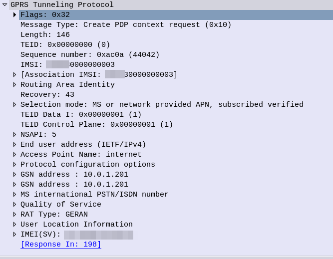
In order to start relaying traffic to/from the S5 & SGi interfaces, the P-GW needs a set of procedures for setting up these sessions, (IP Address allocation and TEID allocation) known as bearers. This is managed using GTPv2 (aka GTPv2-Control Plane / GTPv2-C).
GTPv2-C has a set of procedures for creating these sessions, the key ones used by the P-GW are:
The Create Session Request is sent by the S-GW to the P-GW and contains the APN of the network to be setup, the IP Address to be assigned (if static) and information regarding the maximum throughput the user will be permitted to achieve.
If the P-GW was able to setup the connection as requested, a Create Session Response is sent back to the P-GW, with the IP Address for the UE to use, and the TEID (Tunnel Endpoint Identifier).
At this stage the tunnel is up and ready to go, traffic to the P-GW to the IP of the UE will be encapsulated in GTP-U packets with the TEID for this bearer, and forwarded on to the S-GW serving the user.
As our subscribers are mobile, moving between base stations / cells, the destination of the incoming GTP-U packets needs to be updated every time the subscriber moves from one cell to another.
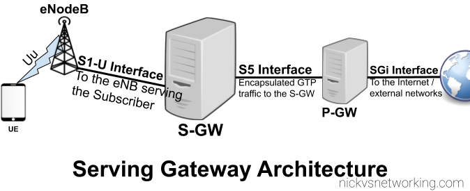
As we covered in the last post, the Packet Gateway (P-GW) handles decapsulating and encapsulating this traffic into GTP from external networks, and vise-versa. The Packet Gateway sends the traffic onto a Serving Gateway, that forwards the GTP-U traffic onto the eNodeB serving the user.
So why not just route the traffic from the Packet Gateway directly to the eNodeB?
As our users are inherently mobile, the signalling load to keep updating the destination of the incoming GTP-U traffic to the correct eNB, would put an immense load on the P-GW. So an intermediary gateway – the Serving Gateway (S-GW), is introduced.
The S-GW handles the mobility between cells, and takes the load of the P-GW. The P-GW just hands the traffic to a S-GW and let’s the S-GW handle the mobility.
It’s worth keeping in mind that most LTE connections are not “always on”. Subscribers (UEs) go into “Idle Mode”, in which the data connection and the radio connection is essentially paused, and able to be bought back at a moments notice (this allows us to get better battery life on the UE and better frequency utilisation).
When a user enters Idle Mode, an incoming packet needs to be buffered until the Subscriber/UE can get paged and come back online. Again this function is handled by the S-GW; buffering packets until the UE comes available then forwarding them on.
Most people think of SIP when it comes to FreeSWITCH, Asterisk and Kamailio, but all three support WebRTC.
FreeSWITCH makes WebRTC fairly easy to use and treats it much the same way as any SIP endpoint, in terms of registration and diaplan.
Setting up the SIP Profile
On the SIP profile we’ll need to activate WebRTC you’ll need to ensure a few lines of config are present:
    <!-- for sip over secure websocket support -->
    <!-- You need wss.pem in $${certs_dir} for wss or one will be created for you -->
    <param name="wss-binding" value=":7443"/>
Next you’ll need to restart FreeSWITCH and a self-signed certificate should get loaded,
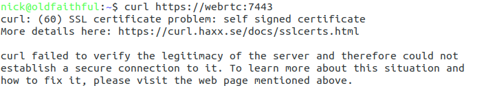
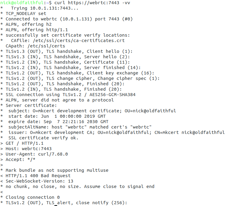
Once you’ve restarted FreeSWITCH will fail to detect any WebSocket certificate and generate a self signed certificate for you. This means that you can verify FreeSWITCH is listening as expected using Curl:
curl https://yourhostname:7443 -vvv
You should see an error regarding the connection failing due to an invalid certificate, if so, great! Let’s put in a valid certificate.
If not double check the firewall on your server allow traffic to port TCP 7443,
Loading your TLS Certificate
WebRTC & websocket are recent standards – this means a valid TLS certificate is mandatory. So to get this to work you’ll need a valid SSL certificate.
When we restarted FreeSWITCH after adding the wss-binding config a certificate was automatically generated in the $${certs_dir} of FreeSWITCH,
You can verify where the certs_dir is by echoing out the variable in FreeSWITCH:
fs_cli -x 'eval $${certs_dir}'
Unless you’ve changed it you’ll probably find your certs in /etc/freeswitch/tls/
The certificate and private key are stored in a single file, with the Certificate and the Private Key appended to the end,
In my case the certificate is called “webrtc.pem” and the private key file is “webrtc-key.pem”,
I’ll need to start by replacing the contents of the current certificate/ key file wss.pem with the certificate I’ve got webrtc.pem, and then appending the private key – webrtc-key.pem to the end of wss.pem,
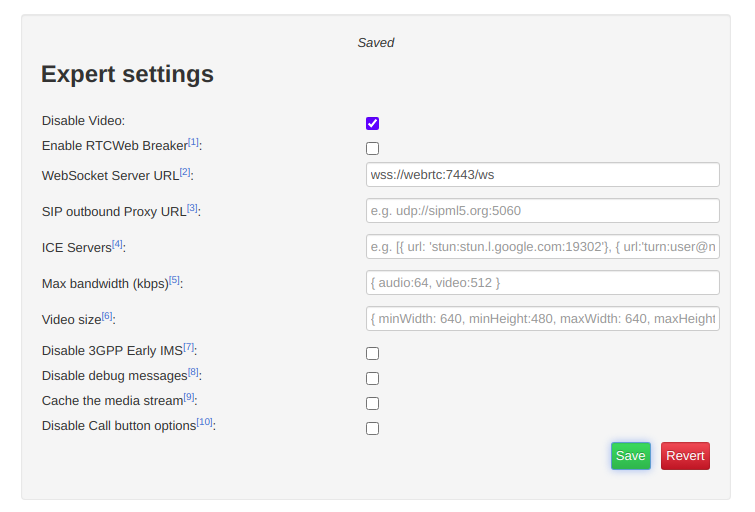
We’ll start by clicking the “Export Mode” button to set our wss:// URL;
Change the WebSocket Server URL to the URL of your FreeSWITCH instance (you must use a domain, not an IP Address)
If you’re running behind a NAT adding ICE servers is probably a good idea, although this will slow down connection times, you can use Google’s public STUN server by pasting in the below value:
[{ url: 'stun:stun.l.google.com:19302'}]
Finally we’ll save those settings and return back to the main tab,
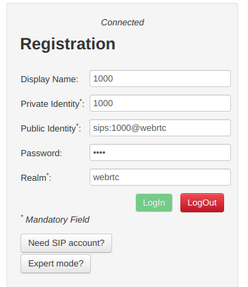
You’ll need to register with a username and password that’s valid on the FreeSWITCH box, in my case I’m using 1000 with the password 1000 (exists by default),
Replace webrtc with the domain name of your FreeSWITCH instance,
Finally you should be able to click Login and see Connected above,
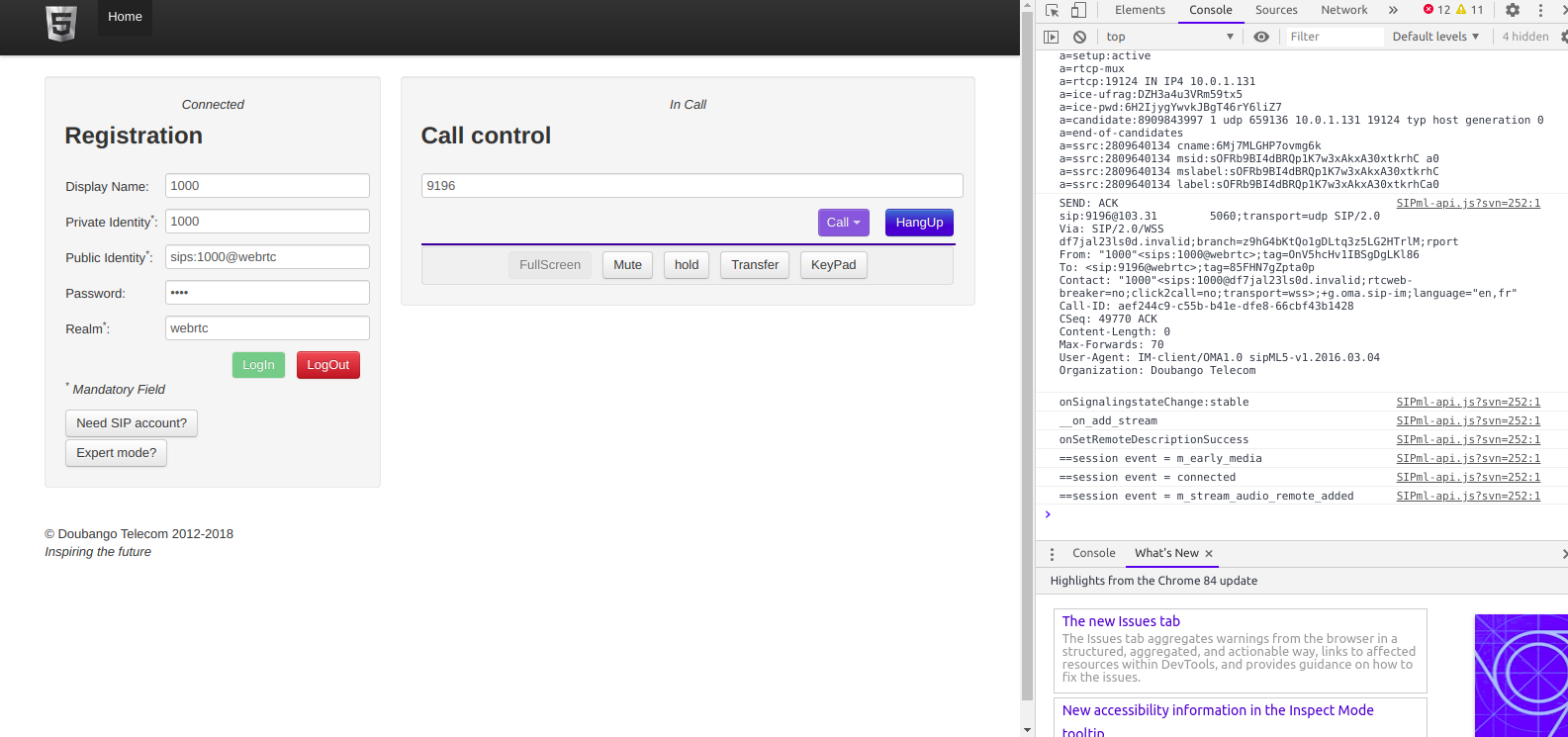
Then we can make calls to endpoints on FreeSWITCH using the dial box;
The Debug console in your browser will provide all the info you need to debug any issues, and you can trace WebSocket traffic using Sofia like any other SIP traffic.
Hopefully this was useful to you – I’ll cover more of WebRTC on Asterisk and also Kamailio in later posts!
It’s a seemingly simple question, the answer to which is – however you want, sorry if that’s not a simple answer.
I’ve talked about the strengths and weaknesses of Kamailio and Asterisk in my post Kamailio vs Asterisk, so how about we use them to work together?
The State of Play
So before we go into the nitty gritty, let’s imagine we’ve got an Asterisk box with a call queue with Alice and Bob in it, set to ring those users if they’re not already on a call.
Each time a call comes in, Asterisk looks at who in the queue is not already on a call, and rings their phone.
Now let’s imagine we’re facing a scenario where the single Asterisk box we’ve got is struggling, and we want to add a second to share the load.
We do it, and now we’ve got two Asterisk boxes and a Kamailio load balancer to split the traffic between the two boxes.
Now each time a call comes in, Kamailio sends the SIP INVITE to one of the two Asterisk boxes, and when it does, that Asterisk box looks at who is in the queue and not already on a call, and then rings their phone.
Let’s imagine a scenario where a Alice & Bob are both on calls on Asterisk box A, and another call comes in this call is routed to Asterisk box B. Asterisk box B looks at who is in the queue and who is already on a call, the problem is Alice and Bob are on calls on Asterisk box A, so Asterisk box B doesn’t know they’re both on a call and tries to ring them.
We have a problem.
Scaling stateful apps is a real headache,
So have a good long hard think about how to handle these issues before going down this path!