SIP routing is complicated, there’s edge cases, traffic that can be switched locally and other traffic that needs to be proxied off to another Proxy or Application server. How can you define these rules and logic in a flexible way, that allows these rules to be distributed out to multiple different network elements and adjusted on a per-subscriber basis?
Enter iFCs – The Initial Filter Criteria.
iFCs are XML encoded rules to define which servers should handle traffic matching a set of rules.
Let’s look at some example rules we might want to handle through iFCs:
- Send all SIP NOTIFY, SUBSCRIBE and PUBLISH requests to a presence server
- Any Mobile Originated SMS to an SMSc
- Calls to a specific destination to a MGC
- Route any SIP INVITE requests with video codecs present to a VC bridge
- Send calls to Subscribers who aren’t registered to a Voicemail server
- Use 3rd party registration to alert a server that a Subscriber has registered
All of these can be defined and executed through iFCs, so let’s take a look,
iFC Structure
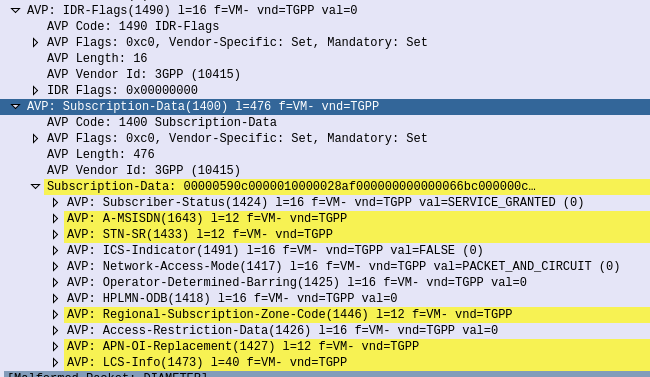
iFCs are encoded in XML and typically contained in the Cx-user-data AVP presented in a Cx Server Assignment Answer response.
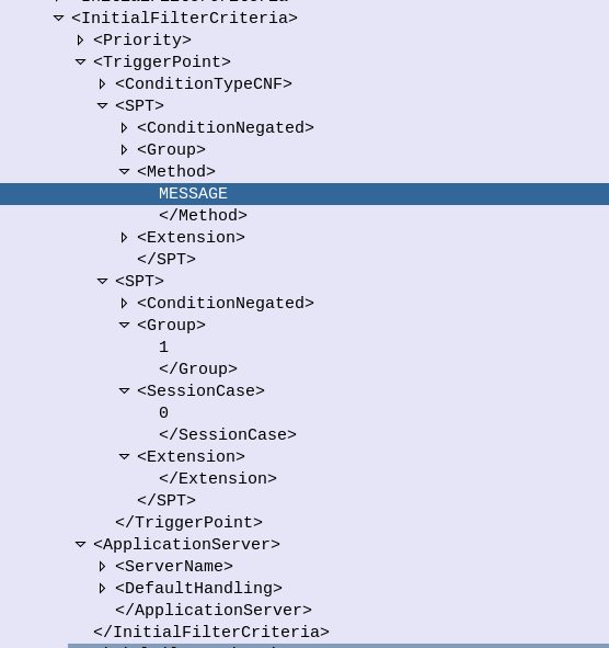
Let’s take a look at an example iFC and then break down the details as to what we’re specifying.
<InitialFilterCriteria>
    <Priority>10</Priority>
    <TriggerPoint>
        <ConditionTypeCNF>1</ConditionTypeCNF>
        <SPT>
            <ConditionNegated>0</ConditionNegated>
            <Group>0</Group>
            <Method>MESSAGE</Method>
        </SPT>
        <SPT>
            <ConditionNegated>0</ConditionNegated>
            <Group>1</Group>
            <SessionCase>0</SessionCase>
        </SPT>
    </TriggerPoint>
    <ApplicationServer>
        <ServerName>sip:smsc.mnc001.mcc001.3gppnetwork.org:5060</ServerName>
        <DefaultHandling>0</DefaultHandling>
    </ApplicationServer>
</InitialFilterCriteria>
Each rule in an iFC is made up of a Priority, TriggerPoint and ApplicationServer.
So for starters we’ll look at the Priority tag.
The Priority tag allows us to have multiple-tiers of priority and multiple levels of matching,
For example if we had traffic matching the conditions outlined in this rule (TriggerPoint) but also matching another rule with a lower priority, the lower priority rule would take precedence.
Inside our <TriggerPoint> tag contains the specifics of the rules and how the rules will be joined / matched, which is what we’ll focus on predominantly, and is followed by the <ApplicationServer> which is where we will route the traffic to if the TriggerPoint is matched / triggered.
So let’s look a bit more about what’s going on inside the TriggerPoint.
Each TriggerPoint is made up of Service Point Trigger (SPTs) which are individual rules that are matched or not matched, that are either combined as logical AND or logical OR statements when evaluated.
By using fairly simple building blocks of SPTs we can create a complex set of rules by joining them together.
Service Point Triggers (SPTs)
Let’s take a closer look at what goes on in an SPT.
Below is a simple SPT that will match all SIP requests using the SIP MESSAGE method request type:
        <SPT>
            <ConditionNegated>0</ConditionNegated>
            <Group>0</Group>
            <Method>MESSAGE</Method>
        </SPT>
So as you may have guessed, the <Method> tag inside the SPT defines what SIP request method we’re going to match.
But Method is only one example of the matching mechanism we can use, but we can also match on other attributes, such as Request URI, SIP Header, Session Case (Mobile Originated vs Mobile Terminated) and Session Description such as SDP.
Or an example of a SPT for anything Originating from the Subscriber utilizing the <SessionCase> tag inside the SPT.
        <SPT>
            <ConditionNegated>0</ConditionNegated>
            <Group>0</Group>
            <SessionCase>0</SessionCase>
        </SPT>
Below is another SPT that’s matching any requests where the request URI is sip:[email protected] by setting the <RequestURI> tag inside the SPT:
        <SPT>
            <ConditionNegated>0</ConditionNegated>
            <Group>0</Group>
            <RequestURI>sip:[email protected]</RequestURI>
        </SPT>
We can match SIP headers, either looking for the existence of a header or the value it is set too,
        <SPT>
            <ConditionNegated>0</ConditionNegated>
            <Group>0</Group>
            <SIPHeader>
              <Header>To</Header>
              <Content>"Nick"</Content>
            </SIPHeader>
        </SPT>
Having <Header> will match if the header is present, while the optional Content tag can be used to match
In terms of the Content this is matched using Regular Expressions, but in this case, not so regular regular expressions. 3GPP selected Extended Regular Expressions (ERE) to be used (IEEE POSIX) which are similar to the de facto standard PCRE Regex, but with a few fewer parameters.
Condition Negated
The <ConditionNegated> tag inside the SPT allows us to do an inverse match.
In short it will match anything other than what is specified in the SPT.
For example if we wanted to match any SIP Methods other than MESSAGE, setting <ConditionNegated>1</ConditionNegated> would do just that, as shown below:
        <SPT>
            <ConditionNegated>1</ConditionNegated>
            <Group>0</Group>
            <Method>MESSAGE</Method>
        </SPT>
And another example of ConditionNegated in use, this time we’re matching anything where the Request URI is not sip:[email protected]:
        <SPT>
            <ConditionNegated>1</ConditionNegated>
            <Group>0</Group>
            <RequestURI>sip:[email protected]</RequestURI>
        </SPT>
Finally the <Group> tag allows us to group together a group of rules for the purpose of evaluating.
We’ll go into it more in in the below section.
ConditionTypeCNF / ConditionTypeDNF
As we touched on earlier, <TriggerPoints> contain all the SPTs, but also, very importantly, specify how they will be interpreted.
SPTs can be joined in AND or OR conditions.
For some scenarios we may want to match where METHOD is MESSAGE and RequestURI is sip:[email protected], which is different to matching where the METHOD is MESSAGE or RequestURI is sip:[email protected].
This behaviour is set by the presence of one of the ConditionTypeCNF (Conjunctive Normal Form) or ConditionTypeDNF (Disjunctive Normal Form) tags.
If each SPT has a unique number in the GroupTag and ConditionTypeCNF is set then we evaluate as AND.
If each SPT has a unique number in the GroupTag and ConditionTypeDNF is set then we evaluate as OR.
Let’s look at how the below rule is evaluated as AND as ConditionTypeCNF is set:
<InitialFilterCriteria>
    <Priority>10</Priority>
    <TriggerPoint>
        <ConditionTypeCNF>1</ConditionTypeCNF>
        <SPT>
            <ConditionNegated>0</ConditionNegated>
            <Group>0</Group>
            <Method>MESSAGE</Method>
        </SPT>
        <SPT>
            <ConditionNegated>0</ConditionNegated>
            <Group>1</Group>
            <SessionCase>0</SessionCase>
        </SPT>
    </TriggerPoint>
    <ApplicationServer>
        <ServerName>sip:smsc.mnc001.mcc001.3gppnetwork.org:5060</ServerName>
        <DefaultHandling>0</DefaultHandling>
    </ApplicationServer>
</InitialFilterCriteria>
This means we will match if the method is MESSAGE and Session Case is 0 (Mobile Originated) as each SPT is in a different Group which leads to “and” behaviour.
If we were to flip to ConditionTypeDNF each of the SPTs are evaluated as OR.
<InitialFilterCriteria>
    <Priority>10</Priority>
    <TriggerPoint>
        <ConditionTypeDNF>1</ConditionTypeDNF>
        <SPT>
            <ConditionNegated>0</ConditionNegated>
            <Group>0</Group>
            <Method>MESSAGE</Method>
        </SPT>
        <SPT>
            <ConditionNegated>0</ConditionNegated>
            <Group>1</Group>
            <SessionCase>0</SessionCase>
        </SPT>
    </TriggerPoint>
    <ApplicationServer>
        <ServerName>sip:smsc.mnc001.mcc001.3gppnetwork.org:5060</ServerName>
        <DefaultHandling>0</DefaultHandling>
    </ApplicationServer>
</InitialFilterCriteria>
This means we will match if the method is MESSAGE and Session Case is 0 (Mobile Originated).
Where this gets a little bit more complex is when we have multiple entries in the same Group tag.
Let’s say we have a trigger point made up of:
<SPT><Method>MESSAGE</Method><Group>1</Group></SPT>
<SPT><SessionCase>0</SessionCase><Group>1</Group></SPT>

<SPT><Header>P-Some-Header</Header><Group>2</Group></SPT>
How would this be evaluated?
If we use ConditionTypeDNF every SPT inside the same Group are matched as AND, and SPTs with distinct are matched as OR.
Let’s look at our example rule evaluated as ConditionTypeDNF:
<ConditionTypeDNF>1</ConditionTypeDNF>
  <SPT><Method>MESSAGE</Method><Group>1</Group></SPT>
  <SPT><SessionCase>0</SessionCase><Group>1</Group></SPT>

  <SPT><Header>P-Some-Header</Header><Group>2</Group></SPT>
This means the two entries in Group 1 are evaluated as AND – So Method is message and Session Case is 0, OR the header “P-Some-Header” is present.
Let’s do another one, this time as ConditionTypeCNF:
<ConditionTypeCNF>1</ConditionTypeCNF>
  <SPT><Method>MESSAGE</Method><Group>1</Group></SPT>
  <SPT><SessionCase>0</SessionCase><Group>1</Group></SPT>

  <SPT><Header>P-Some-Header</Header><Group>2</Group></SPT>
This means the two entries in Group 1 are evaluated as OR – So Method is message OR Session Case is 0, AND the header “P-Some-Header” is present.