As Open5Gs has introduced network slicing, which led to a change in the database used,
Alas many users had subscribers provisioned in the old DB schema and no way to migrate the SDM data between the old and new schema,
If you’ve created subscribers on the old schema, and now after the updates your Subscriber Authentication is failing, check out this tool I put together, to migrate your data over.
A seperate server (hss_sctp.py) is run to handle SCTP connections, and if you’re looking for Multihoming, we got you dawg – Just edit the config file and set the bind_ip list to include each of your IPs to multi home listen on.
Every now and then when looking into a problem I have to really stop and think about how things work low down, that I haven’t thought about for a long time, and MTU is one of those things.
I faced with an LTE MTU issue recently I thought I’d go back and brush up on my MTU knowhow and do some experimenting.
Note: This is an IPv4 discussion, IPv6 does not support fragmentation.
The very, very basics
MTU is the Maximum Transmission Unit.
In practice this is the largest datagram the layer can handle, and more often than not, this is based on a physical layer constraint, in that different physical layers can only stuff so much into a frame.
“The Internet” from a consumer perspective typically has an MTU of 1500 bytes or perhaps a bit under depending on their carrier, such as 1472 bytes. SANs in data centers typically use an MTU of around 9000 bytes, Out of the box, most devices if you don’t specify, will use an MTU of 1500 bytes.
As a general rule, service providers typically try to offer an MTU as close to 1500 as possible.
Messages that are longer than the Maximum Transmission Unit need to be broken up in a process known as “Fragmenting”. Fragmenting allows large frames to be split into smaller frames to make their way across hops with a lower MTU.
All about Fragmentation
So we can break up larger packets into smaller ones by Fragmenting them, so case closed on MTU right? Sadly not.
Fragmentation leads to reduced efficiency – Fragmenting frames takes up precious CPU cycles on the router performing it, and each time a frame is broken up, additional overhead is added by the device breaking it up, and by the receiver to reassemble it.
Fragmentation can happen multiple times across a path (Multi-Stage Fragmentation). For example if a frame is sent with a length of 9000 bytes, and needs to traverse a hop with an MTU of 4000, it would need to be fragmented (broken up) into 3 frames (Frame 1 and Frame 2 would be ~4000 bytes long and frame 3 would be ~1000 bytes long). If it then needs to traverse another hop with an MTU of 1500, then the 3 fragmented frame would each need to be further fragmented, with the first frame of ~4000 bytes being split up into 3 more fragmented frames. Lost track of what just happened? Spare a thought for the routers having to to do the fragmentation and the recipient having to reassemble their packets.
Fragmented frames are reassembled by the end recipient, other devices along the transmission path don’t reassemble packets.
In the end it boils down to this trade off: The larger the packet can be, the more user data we can stuff into each one as a percentage of the overall data. We want the percentage of user data for each packet to be as high as can be. This means we want to use the largest MTU possible, without having to fragment packets.
Overhead eats into our MTU
A 1500 byte MTU that has to be encapsulated in IPsec, GTP or PPP, is no longer a 1500 byte MTU as far as the customer is concerned.
Any of these encapsulation techniques add overhead, which shrinks the MTU available to the end customer.
This means we’ve got 50 bytes of transmission / transport overhead. This will be important later on!
How do subscribers know what to use as MTU?
Typically when a subscriber buys a DSL service or HFC connection, they’ll either get a preconfigured router from their carrier, or they will be given a list of values to use that includes MTU.
LTE and 5G on the other hand tell us the value we should use.
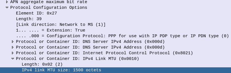
Inside the Protocol Configuration Options in the NAS PDU, the UE requests the MTU and DNS server to be used, and is provided back from the network.
This MTU value is actually set on the MME, not the P-GW. As the MME doesn’t actually know the maximum MTU of the network, it’s up to the operator to configure this to be a value that represents the network.
Why this Matters for LTE & 5G Transmission
As we covered earlier, fragmentation is costly. If we’re fragmenting packets we are:
Wasting resources on our transmission network / core networks – as we fragment Subscriber packets it’s taking up compute resources and therefore limiting throughput
Wasting radio resources as additional overhead is introduced for fragmented packets, and additional RBs need to be scheduled to handle the fragmented packets
To test this I’ve setup a scenario in the lab, and we’ll look at the packet captures to see how the MTU is advertised, and see how big we can make our MTU on the subscriber side.
Our BTS is going to need an accurate clock source in order to run, so without access to crazy accurate Timing over Packet systems or TDM links to use as reference sources, I’ve opted to use the GPS/GLONASS receiver built into the LMPT card.
Add new GPS with ID 0 on LMPT in slot 7 of cabinet 1:
Check GPS has sync (May take some time) using the Display GPS command;
DSP GPS: GN=0;
Assuming you’ve got an antenna connected and can see the sky, after ~10 minutes running the DSP GPS:; command again should show you an output like this:
+++    4-PAL0089624        2020-11-28 01:06:55
O&M    #806355684
%%DSP GPS: GN=0;%%
RETCODE = 0  Operation succeeded.

Display GPS State
-----------------
                 GPS Clock No.  =  0
                GPS Card State  =  Normal
                 GPS Card Type  =  M12M
                 GPS Work Mode  =  GPS
                   Hold Status  =  UNHOLDED
         GPS Satellites Traced  =  4
     GLONASS Satellites Traced  =  0
         BDS Satellites Traced  =  0
Antenna Longitude(1e-6 degree)  =  144599999
 Antenna Latitude(1e-6 degree)  =  -37000000
           Antenna Altitude(m)  =  613
         Antenna Angle(degree)  =  5
             Link Active State  =  Activated
              Feeder Delay(ns)  =  15
                   GPS Version  =  NULL
(Number of results = 1)


---    END
Showing the GPS has got sync and a location fix,
Next we set BTS to use GPS as time source,
SET TIMESRC: TIMESRC=GPS;
Finally we’ll verify the Time is in sync on the BTS using the list time command:
DSP TIME:;
+++    4-PAL0089624        2020-11-28 01:09:22
O&M    #806355690
%%DSP TIME:;%%
RETCODE = 0  Operation succeeded.

Time Information
----------------
Time  =  2020-11-28 01:09:22 GMT+00:00

---    END
Optionally you may wish to add a timezone, using the SET TZ:; command, but I’ve opted to keep it in UTC for simplicity.
Recently I’ve been wrapping my head around Cell Broadcast in LTE, and thought I’d share my notes on 3GPP TS 38.413.
The interface between the MME and the Cell Broadcast Center (CBC) is the SBc interface, which as two types of “Elementary Procedures”:
Class 1 Procedures are of the request – response nature (Request followed by a Success or Failure response)
Class 2 Procedures do not get a response, and are informational one-way. (Acked by SCTP but not an additional SBc message).
SCTP is used as the transport layer, with the CBC establishing a point to point connection to the MME over SCTP (Unicast only) on port 29168 with SCTP Payload Protocol Identifier 24.
The SCTP associations between the MME and the CBC should normally remain up – meaning the SCTP association / transport connection is up all the time, and not just brought up when needed.
Elementary Procedures
Write-Replace Warning (Class 1 Procedure)
The purpose of Write-Replace Warning procedure is to start, overwrite the broadcasting of warning message, as defined in 3GPP TS 23.041 [14].
Write-Replace Warning procedure, initiated by WRITE-REPLACE WARNING REQUEST sent by the CBC to the MMEs contains the emergency message to be broadcast and the parameters such as TAC to broadcast to, severity level, etc.
A WRITE-REPLACE WARNING RESPONSE is sent back by the MME to the MME, if successful, along with information as to where it was sent out. CBC messages are unacknowledged by UEs, meaning it’s not possible to confirm if a UE has actually received the message.
The request includes the message identifier and serial number, list of TAIs, repetition period, number of broadcasts requested, warning type, and of course, the warning message contents.
Stop Warning Procedure (Class 1 Procedure)
Stop Warning Procedure, initiated by STOP WARNING REQUEST and answered with a STOP WARNING RESPONSE, requests the MME inform the eNodeBs to stop broadcasting the CBC in their SIBs.
Includes TAIs of cells this should apply to and the message identifier,
Error Indication (Class 2)
The ERROR INDICATION is used to indicate an error (duh). Contains a Cause and Criticality IEs and can be sent by the MME or CBC.
Write Replace Warning (Class 2)
The WRITE REPLACE WARNING INDICATION is used to indicate warning scenarios for some instead of a WRITE-REPLACE WARNING RESPONSE,
PWS Restart (Class 2)
The PWS RESTART INDICATION is used to list the eNodeBs / cells, that have become available or have restarted, since the CBC message and have no warning message data – for example eNodeBs that have just come back online during the period when all the other cells are sending Cell Broadcast messages.
Returns a the Restarted-Cell-List IE, containing the Global eNB ID IE and List of TAI, of the restarted / reconnected cells.
PWS Failure Indication (Class 2)
The PWS FAILURE INDICATION is essentially the reverse of PWS RESTART INDICATION, indicating which eNodeBs are no longer available. These cells may continue to send Cell Broadcast messages as the MME has essentially not been able to tell it to stop.
Contains a list of Failed cells (eNodeBs) with the Global-eNodeB-ID of each.
This post is one in a series documenting my adventures attempting to configure a used BTS 3900 to function as a eNB in my lab.
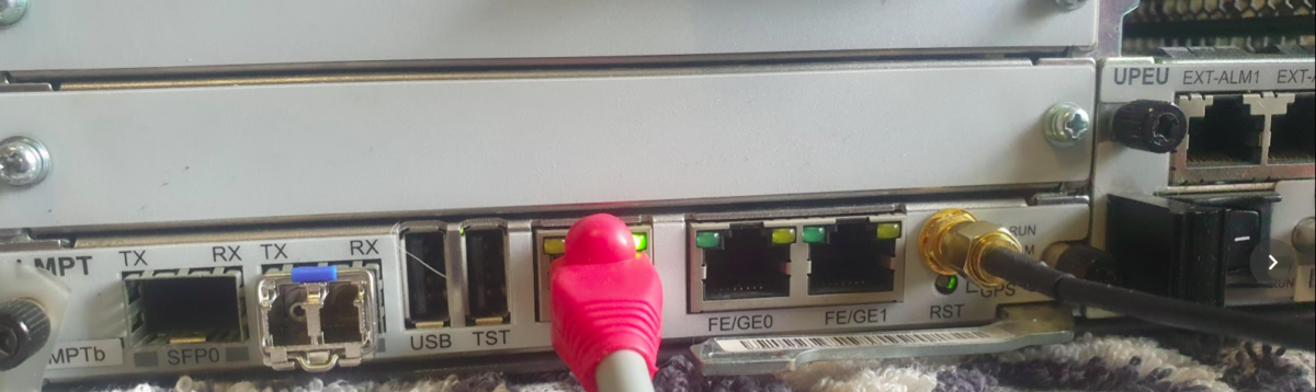
There are 5 network ports on the LMPT card:
2x SFP cages – SFP 0 and SFP 1
1x 10/100 Ethernet port – ETH – Used to access the Local Maintenance terminal
2x Fe/Ge ports – Fe/Ge0 and Fe/Ge1
Configuring the Ethernet Ports
What took me a little while to realise is that SFP0 and Fe/Ge0 are paired, they’re really only one interface. This means you can only use one at a time – you can’t use SFP0 and Fe/Ge0 simultaneously- Same with SFP1 and Fe/Ge1.
Before we get started we’ll list the current interfaces:
DSP ETHPORT:;
Assuming the interfaces aren’t there, we’ll need to add the interfaces, in my case the LMPT card is in Chassis 1, Slot number 7.
And then we’ve got to add an IP to one of the interfaces, in the below example I’ve added 10.0.1.210/24 to port 0 (which can be either SFP0 or Fe/Ge0).
At this point I plugged into the Fe/Ge0 port into my switch, and from my laptop on the same 10.0.1.0/24 subnet, I was able to ping the eNodeB.
And now we can check the status of the port:
DSP ETHPORT: SRN=1, SN=7, SBT=BASE_BOARD, PN=0;
+++    4-PAL0089624        2020-11-28 00:19:13
O&M    #806355532
%%DSP ETHPORT: SRN=1, SN=7, SBT=BASE_BOARD;%%
RETCODE = 0  Operation succeeded.

DSP ETHPORT Result
------------------
                           Cabinet No.  =  0
                           Subrack No.  =  1
                              Slot No.  =  7
                         Subboard Type  =  Base Board
                              Port No.  =  0
                        Port Attribute  =  Copper
                           Port Status  =  Up
                 Physical Layer Status  =  Up
       Maximum Transmission Unit(byte)  =  1500
                             ARP Proxy  =  Enable
                          Flow Control  =  Open
                           MAC Address  =  DCD2-07FC-A9E8
                       Loopback Status  =  No Loop
               In Loopback Mode or Not  =  No
                 Ethernet OAM 3AH Flag  =  Disable
          Number of RX Packets(packet)  =  1682
              Number of RX Bytes(byte)  =  163929
Number of RX CRC Error Packets(packet)  =  2
                    RX Traffic(byte/s)  =  259
          Number of TX Packets(packet)  =  53
              Number of TX Bytes(byte)  =  13952
                    TX Traffic(byte/s)  =  0
  Local Configuration Negotiation Mode  =  Automatic Negotiation
         Local Actual Negotiation Mode  =  Automatic Negotiation
                           Local Speed  =  100M
                          Local Duplex  =  Full Duplex
          Peer Actual Negotiation Mode  =  Automatic Negotiation
                            Peer Speed  =  100M
                           Peer Duplex  =  Full Duplex
                         Number of IPs  =  1
                       IP Address List  =  10.0.1.210 255.255.255.0
(Number of results = 1)


---    END
And with that, you’ve got the network side of the config done on the eNodeB.
At this stage you’re able to unplug from the ETH port you’ve got the WebLMT connection to, and just connect to it like any other network device.
There’s a few more steps before we bring cells on the air, we’ve got to set timing sources, configure a connection to an MME and S-GW, configure the Carrier settings and add the radios and sectors, but this will get you to the stage where you no longer need to plug directly into the eNB to configure it.
How do humans talk to base stations? For Huawei at least the answer to this is through MML – Man-Machine-Language,
It’s command-response based, which is a throwback to my Nortel days (DMS100 anyone?),
So we’re not configuring everything through a series of parameters broken up into sections with config, it’s more statements to the BTS along the lines of “I want you to show me this”, or “Please add that” or “Remove this bit”,
The instruction starts of with an operation word, telling the BTS what we want to do, there’s a lot of them, but some common examples are; DSP (Display), LST (List), SET (Set), MOD (Modify) and ADD (Add).
After the operation word we’ve got the command word, to tell the BTS on what part we want to execute this command,
A nice simple example would be to list the software version that’s running on the BTS. For this we’d run
LST SOFTWARE:;
And press F9 to execute, which will return a list of software on the BTS and show it in the terminal.
Note at the end the :; – the : (colon) denotes the end of a command word, and after it comes the paratmeters for the command, and then the command ends with the ; (semi-colon). We’ll need to put this after every command.
Let’s look at one more example, and then we’ll roll up our sleves and get started.
Note: I’m trying out GIFs to share screen recordings instead of screenshots. Please let me know if you’re having issues with them.
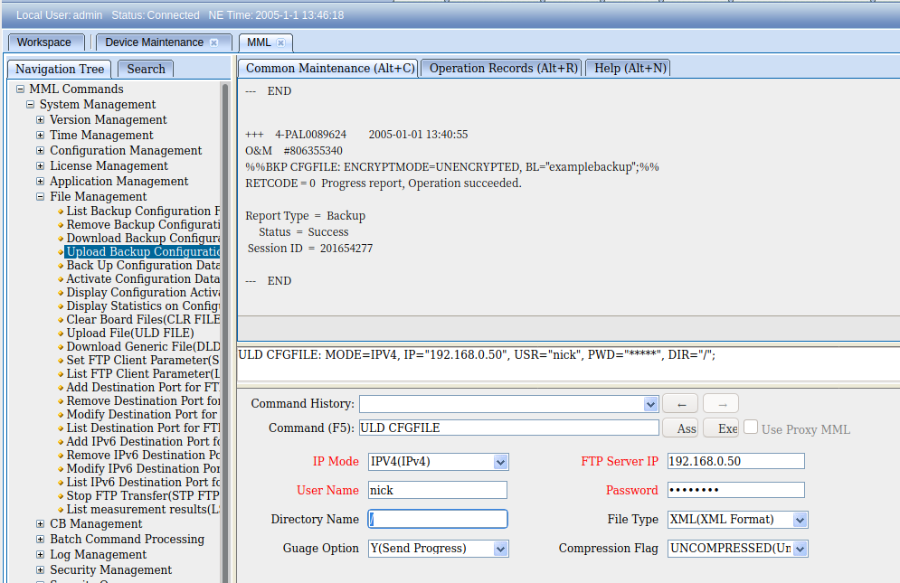
So once you’ve logged into WebLMT, selecting MML is where we’ll do all our config, let’s log in and list the running applications.
So far we’ve only got some fairly basic data, listing and displaying values, so let’s try something a bit more complex, taking a backup of the config, in encrypted mode, with the backup label “blogexamplebackup”,
If you’ve made it this far there’s a good chance you’re thinking there’s no way you can remember all these commands and parameters – But I’ve got some good news, we don’t really need to remember anything, there’s a form for this!
And if we want to upload the backup file to an FTP server, we can do this as well, in the navigation tree we find Upload Backup Configuration, fill in the fields and click the Exec button to execute the command, or press F9.
These forms, combined with a healthy dose of the search tab, allow us to view and configure our BTS.
I’ve still got a lot to learn about getting end-to-end configuration in place, but this seems like a good place to start,
Note: This is one part of a series of posts where I cover my adventures attempting to bring on air a commercial Macro cell site for my lab, with scrounged components.
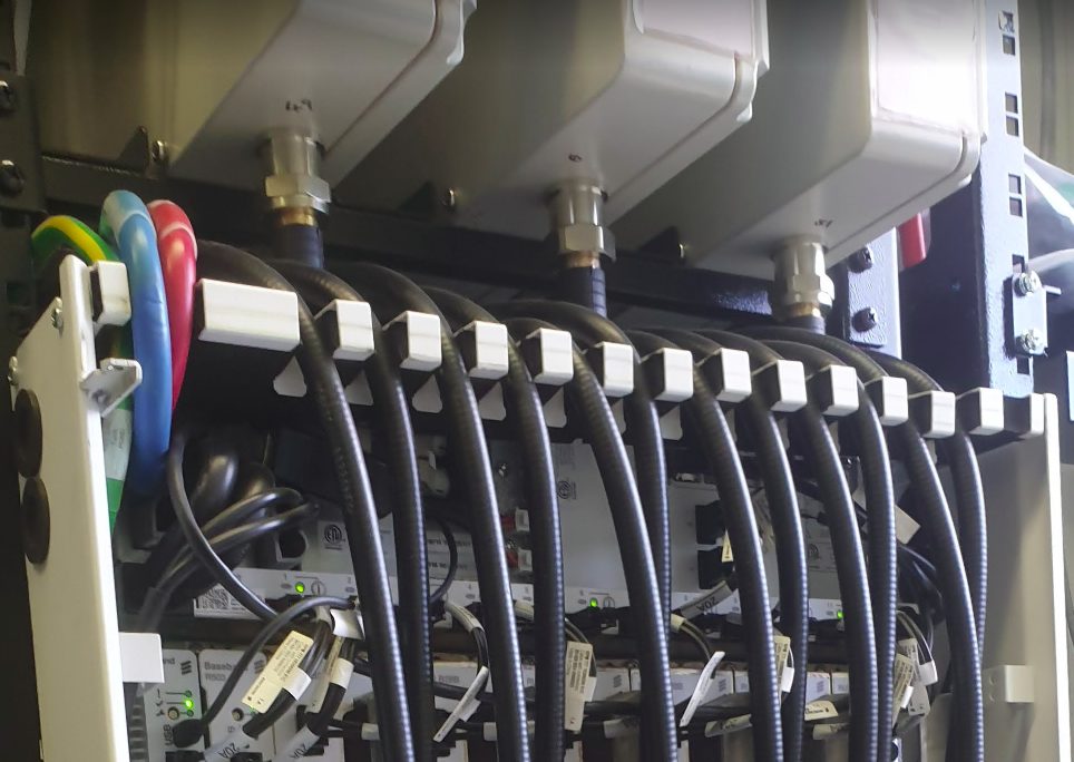
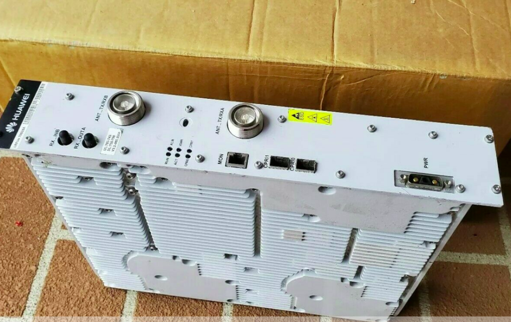
So the Huawei BTS3900 unit I’ve ended up with, is only one part of the overall picture for building a working LTE RAN. Power systems, feeders, connectors, CPRI, antennas, baseband processing and transmission are all hurdles I’ve still got to overcome. So today, let’s talk about antennas!
For the output/TX side (downlink) of the RF Unit, I’ve ordered some 25w 50 ohm dummy loads (I’ll still need to work out how to turn down the RF power to less than 25w on the RF units). Even with the dummy load, a tiny bit of RF power is leaked, which should be enough to provide the downlink signal for my UEs – Time will tell if this works…
This option is fine for the power being pushed out of the RF unit, into the dummy load, where we have a lot of power available (too much power), but what about our very weak uplink signals from UEs?
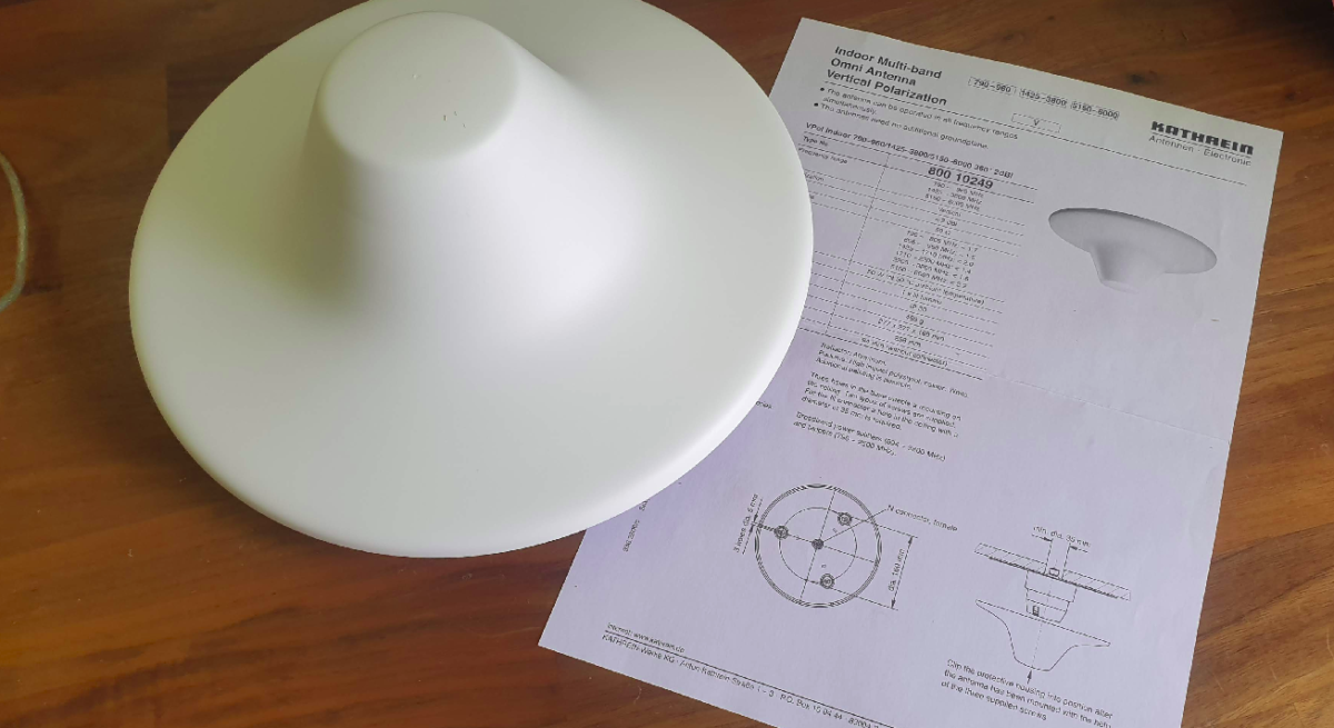
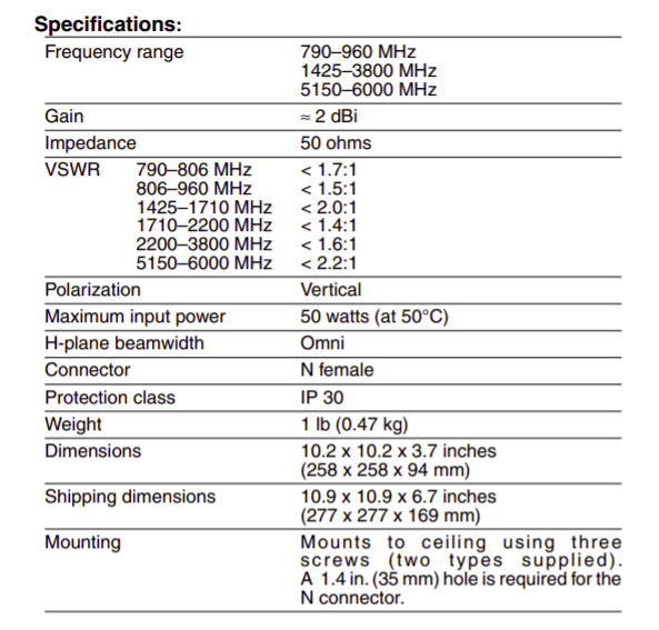
For this I’d need some decent antennas to pickup the signals from the UEs, so I ended up with some Kathrein (Now owned by Ericsson) indoor multi-band omni antennas I found on an online auction site for $10 each. (I bought 4 so I can play with MIMO.)
Unfortunately, the RFUs I have are Band 28 (roughly 700Mhz-750Mhz uplink and 758Mhz to 798Mhz downlink), and reading the datasheet it seems this doesn’t cover the bands I need;
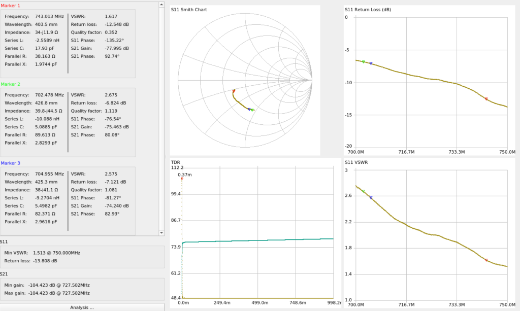
But beggars can’t be choosers, so I ran a calibration on the NanoVNA and swept the antenna from 700Mhz-750Mhz (Band 28 uplink frequencies) to see how it will perform when I get the rest of the solution together;
At the upper end of Band 28 Uplink (748Mhz) I’m getting a fairly respectable VSWR of 1.6 (Return Loss of -12.4dB), so I should be able to get away with these for what I’m doing,
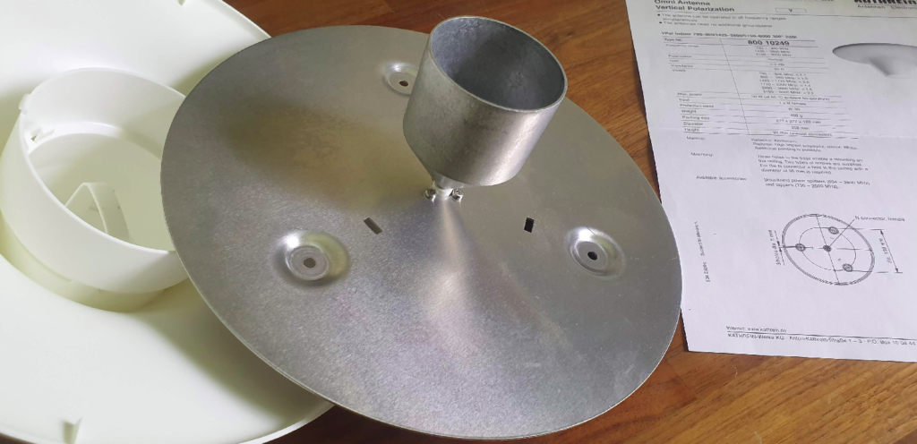
I’v seen these white domes inside shopping centers and office buildings, so I was keen to crack open the case and see what magic inside, what I found was kind of underwhelming, just an aluminum plate with an aluminum reflector cone…
My ideas of putting the parts into the lathe and trying to lower it’s operating frequency by taking material off, were dashed when I realised taking material off would raise the operating frequency, not lower it…
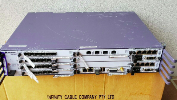
Meta: The Australian government made up it’s mind some time ago that Huawei would be blacklisted from providing equipment for 5G networks. Several other countries have adopted the same policy in regards, and as such, deployed Huawei tech is being replaced, and some of it filters down to online auction sites…
So I kind of purchased an item described as “Huawei BBU3900” with a handful of unknown cards and 2 LRFU units, for just over $100.
My current lab setup is a single commercial picocell and a draw of SDR hardware that works with mixed results, so the idea of having a commercial macro cell to play with seemed like a great idea, I put lowball offer in and the seller accepted.
Now would be a good time to point out I don’t know much about RAN and it’s been a long time since I’ve been working on power systems, so this is shaping up to be a fun project.
Photo from the listing
Photo from the listing
I did a Huawei RAN course years ago and remembered the rough ingredients required for LTE:
You needed either RRUs (Remote Radio Units) or RFUs (Radio Frequency Units) to handle the RF side of things. RRUs are designed for outdoor use (such as mounting on the tower) and RFUs are designed for indoor use, like mounting in a cabinet. I’ve ended up with two LRFUe units, which I can join together for 2x MIMO, operate on Band 28 and can put out a whopping 80W of transmit power, yes I’m going to need some big attenuators…
You need a Baseband Processor card to tell the Radio units what do do. The card connects the CPRIs (Typically optic fiber links) between the radio units and the baseband. The chassis I purchased came with a stack of WBBP (For WCDMA) cards and a single LBBP card for LTE. The LBBP card has 6 SFP ports for the CPRI interfaces, which is more than enough for my little lab. (You can also daisy-chain CPRIs so I’m not even limited to 6 Radio Units.)
You need a backplane and a place for the cards to live – this is the BBU3900 chassis. It’s got basic switching to allow communication between cards, a chassis to distribute power and cooling. (Unlike the Ericson units there is actually a backplane for communications in the Huawei chassis – the Ericsson RBS series has is just power and cooling in the chassis)
Optional – Dedicated transmission card, I’ve ended up with a Universal Transmission Processor (UTRP9) with 2x Gig Ethernet and 2x Fast Ethernet ports for transmission. This will only work for GSM and UMTS though, not LTE, so not much use for me.
You need something to handle main processing (LTE / Universal Main Processing and Transmission Unit (LMPT / UMPT)). Unfortunately the unit I’ve ended up with only came with a WMPT (For WCDMA), so back online to find either an LMPT (LTE) or UMPT (Universal (2G/3G/4G))…
You need a Universal Power and Environment Module (UPEU) to power up the chassis and handle external IO for things like temperature alarms, door sensors and fire detectors. This chassis has two for redundancy / extra IO & extra power capacity.
So in order to get this running I still need quite a few components:
Attenuators – I’ll be able to turn the power down, sure, but not to the levels required to be legal.
Antennas – These are FDD units, so I’ll need two antennas for each RFU, on Band 28
Feeder Cables – To connect the antennas
SMF cables and SFPs – I’ve got a pile in my toolbox, but I’ll need to work out what’s supported by these units
A big -48vDC rectifier (I got the BBU3900 unit powered up with an existing supply I had, but I’m going to need something bigger for the power hungry RFUs)
DC Distribution Unit – Something to split the DC between the RFUs and the BBU, and protect against overload / short
USB-Network adapter – For OAM access to the unit – Found these cheaply online and got one on the way
The LTE Main Processing & Transmission (LMPT) card – Ordered a second hand one from another seller
I powered up the BTA3900 and sniffed the traffic, and can see it trying to reach an RNC.
Unfortunately with no open source RNC options I won’t be posting much on the topic of UMTS or getting the UMTS/WCDMA side of things on the air anytime soon…
So that’s the start of the adventure.
I don’t know if I’ll get this all working, but I’m learning a lot in the process, and that’s all that really matters…
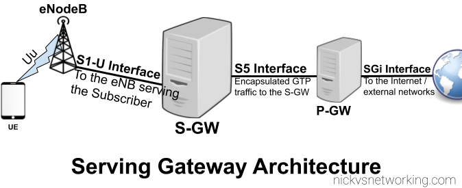
As our subscribers are mobile, moving between base stations / cells, the destination of the incoming GTP-U packets needs to be updated every time the subscriber moves from one cell to another.
As we covered in the last post, the Packet Gateway (P-GW) handles decapsulating and encapsulating this traffic into GTP from external networks, and vise-versa. The Packet Gateway sends the traffic onto a Serving Gateway, that forwards the GTP-U traffic onto the eNodeB serving the user.
So why not just route the traffic from the Packet Gateway directly to the eNodeB?
As our users are inherently mobile, the signalling load to keep updating the destination of the incoming GTP-U traffic to the correct eNB, would put an immense load on the P-GW. So an intermediary gateway – the Serving Gateway (S-GW), is introduced.
The S-GW handles the mobility between cells, and takes the load of the P-GW. The P-GW just hands the traffic to a S-GW and let’s the S-GW handle the mobility.
It’s worth keeping in mind that most LTE connections are not “always on”. Subscribers (UEs) go into “Idle Mode”, in which the data connection and the radio connection is essentially paused, and able to be bought back at a moments notice (this allows us to get better battery life on the UE and better frequency utilisation).
When a user enters Idle Mode, an incoming packet needs to be buffered until the Subscriber/UE can get paged and come back online. Again this function is handled by the S-GW; buffering packets until the UE comes available then forwarding them on.
The S1 interface can be pretty noisy, which makes it hard to find the info you’re looking for.
So how do we find all the packets relating to a single subscriber / IMSI amidst a sea of S1 packets?
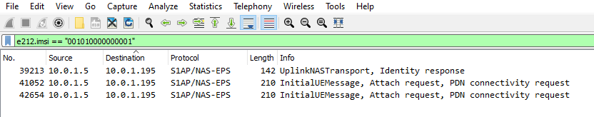
The S1 interface only contains the IMSI in certain NAS messages, so the first step in tracing a subscriber is to find the initial attach request from that subscriber containing the IMSI.
Luckily we can filter in Wireshark to find the IMSI we’re after;
Quick note – Not all IntialUEMessages will contain the IMSI – If the subscriber has already established comms with the MME it’ll instead be using a temporary identifier – M-TMSI, unless you’ve got a way to see the M-TMSI -> IMSI mapping on the MME you’ll be out of luck.
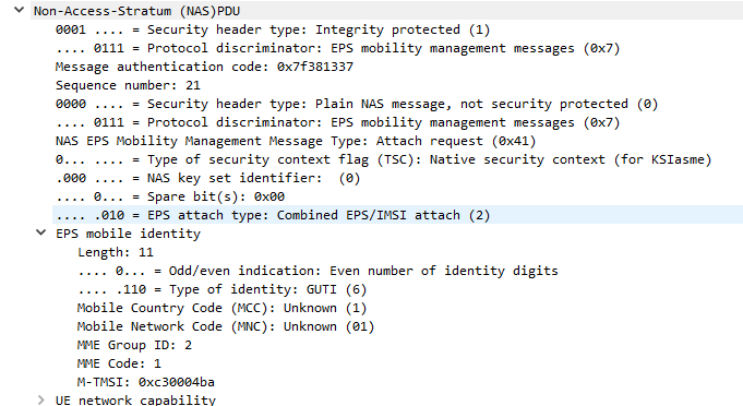
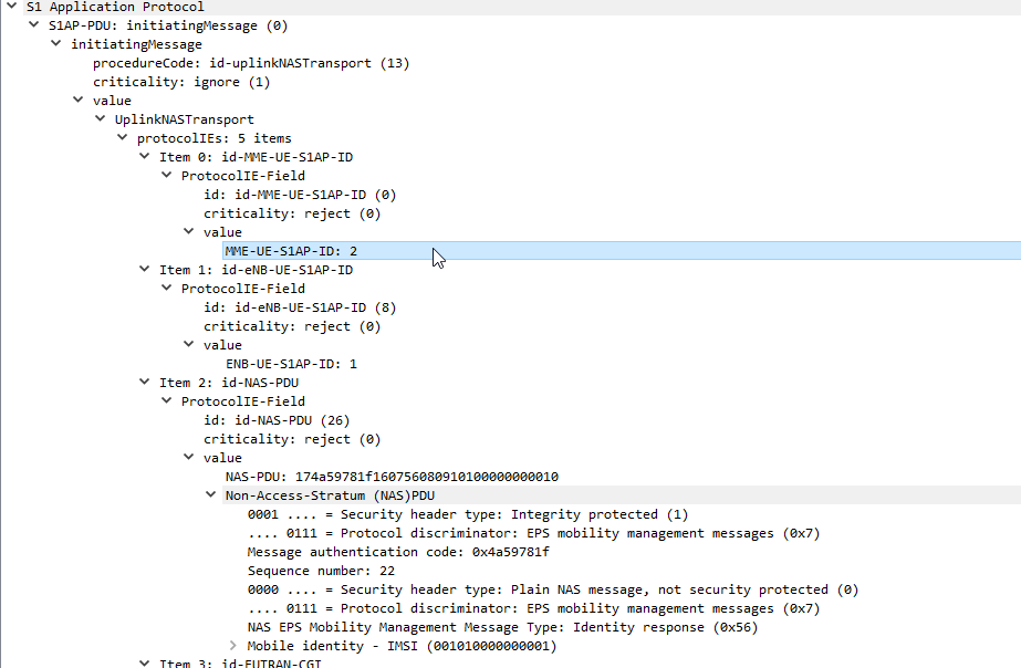
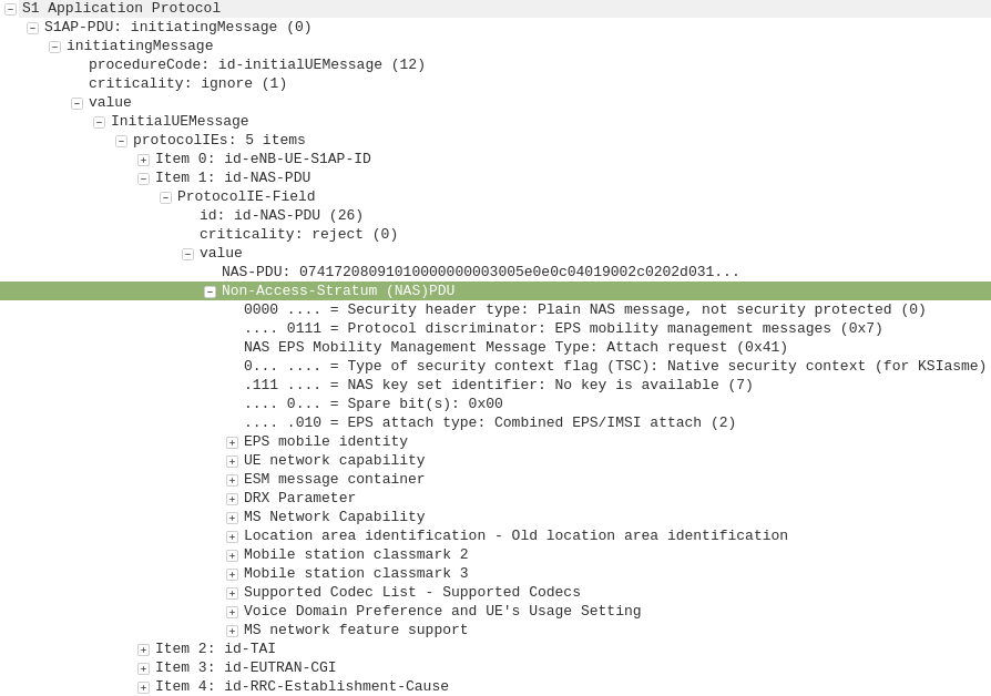
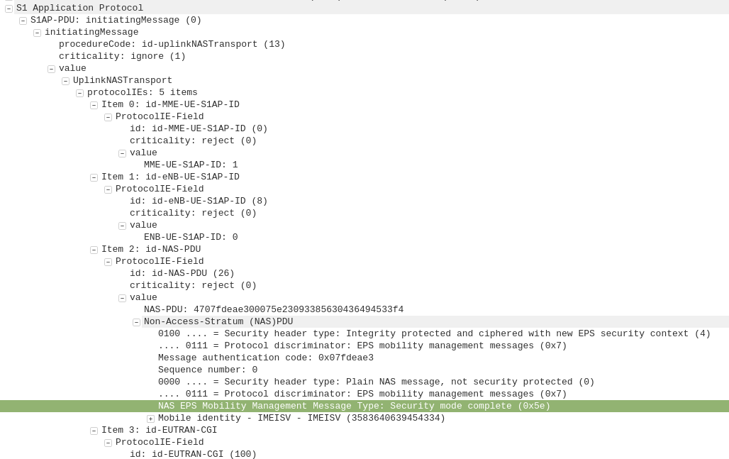
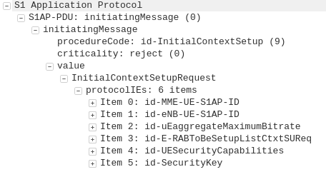
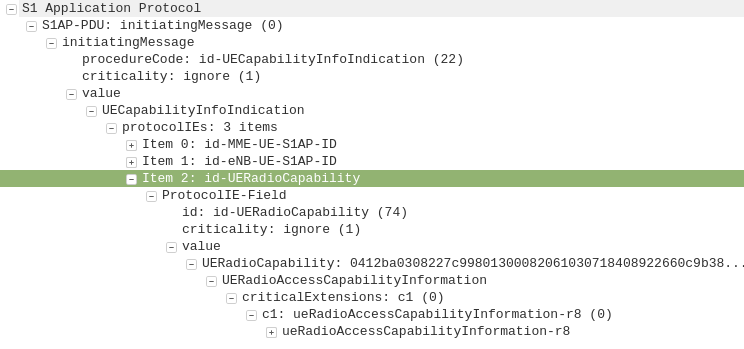
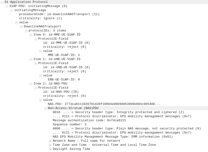
Next up let’s take a look at the contents of one of these packets,
Inside the protocolIEs is the MME_UE_S1AP_ID – This unique identifier will identify all S1 signalling for a single user.
The MME_UE_S1AP_ID is a unique identifier, assigned by the MME to identify which signaling messages are for which subscriber.
(It’s worth noting the MME_UE_S1AP_ID is only unique to the MME – If you’ve got multiple MMEs the same MME_UE_S1AP_ID could be assigned by each).
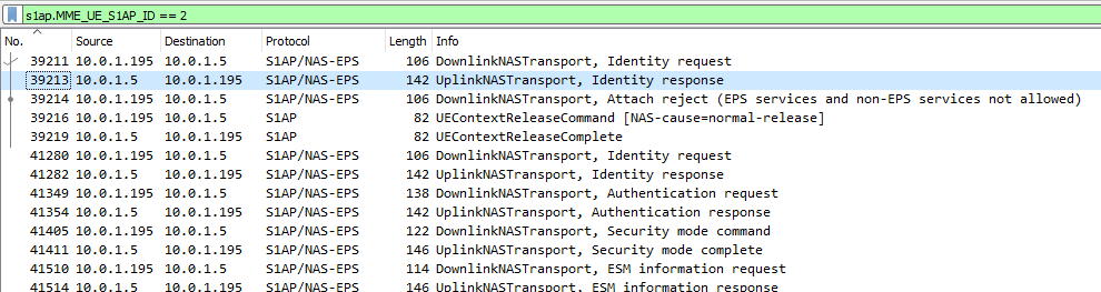
So now we have the MME_UE_S1AP_ID, we can filter all S1 messaging containing that MME_UE_S1AP_ID, we’ll use this Wireshark filter to get it:
s1ap.MME_UE_S1AP_ID == 2
Boom, there’s a all the signalling for that subscriber.
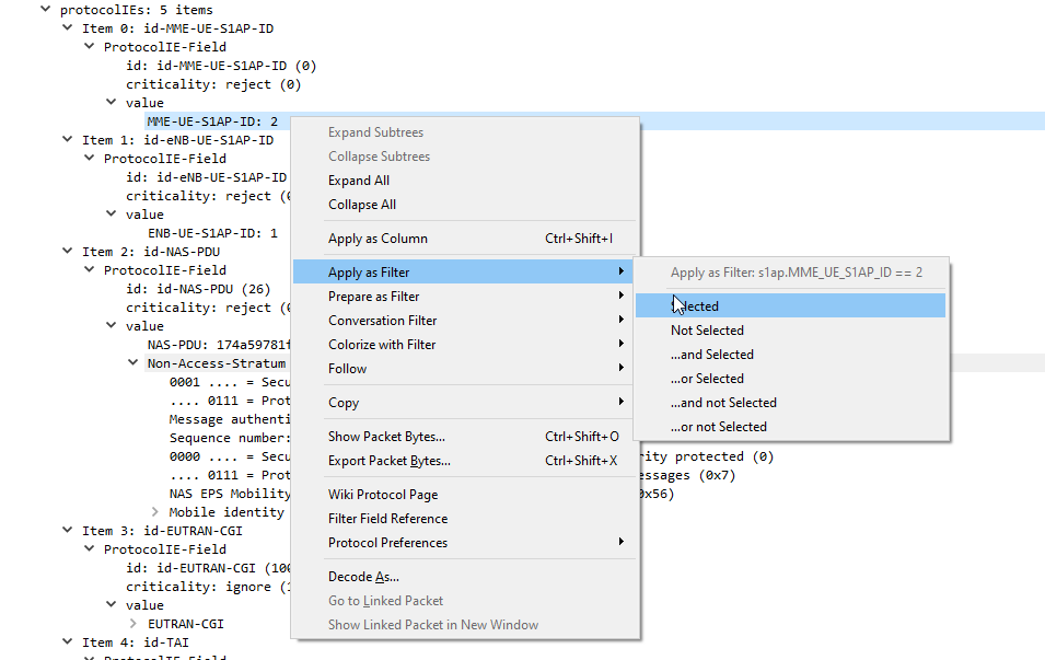
Alternatively you can just right click on the value and apply it as a filter instead of typing everything in,
Hopefully that’ll help you filter to find what you’re looking for!
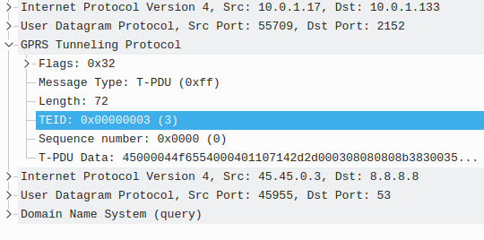
If you’re using an GSM / GPRS, UMTS, LTE or NR network, there’s a good chance all your data to and from the terminal is encapsulated in GTP.
GTP encapsulates user’s data into a GTP PDU / packet that can be redirected easily. This means as users of the network roam around from one part of the network to another, the destination IP of the GTP tunnel just needs to be updated, but the user’s IP address doesn’t change for the duration of their session as the user’s data is in the GTP payload.
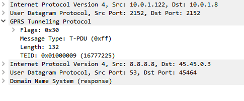
One thing that’s a bit confusing is the TEID – Tunnel Endpoint Identifier.
Each tunnel has a sender TEID and transmitter TEID pair, as setup in the Create Session Request / Create Session Response, but in our GTP packet we only see one TEID.
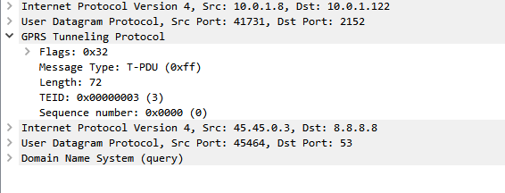
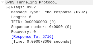
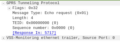
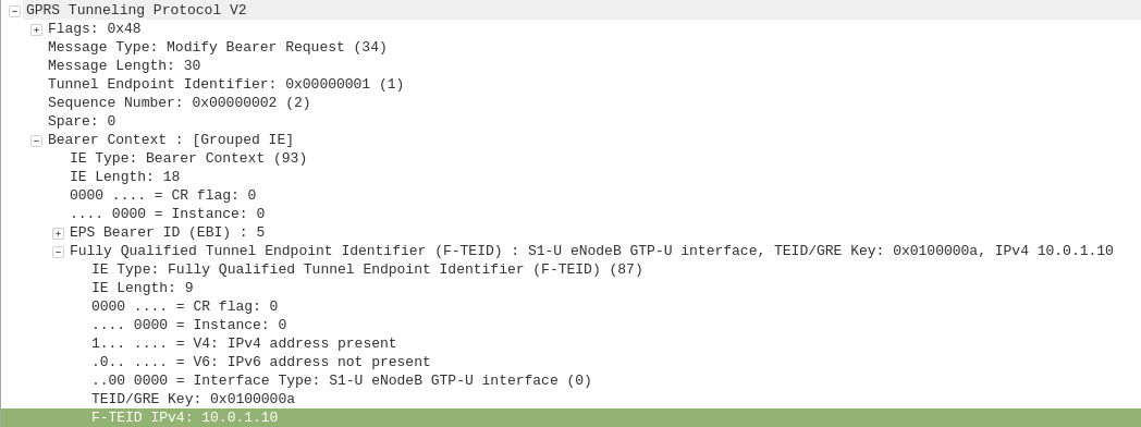
There’s not much to a GTP-U header; at 8 bytes in all it’s pretty lightweight. Flags, message type and length are all pretty self explanatory. There’s an optional sequence number, the TEID value and the payload itself.
So the TEID identifies the tunnel, but it’s worth keeping in mind that the TEID only identifies a data flow from one Network Element to another, for example eNB to S-GW would have one TEID, while S-GW to P-GW would have another TEID.
Each tunnel has two TEIDs, a sending TEID and a receiving TEID. For some reason (Minimize overhead on backhaul maybe?) only the sender TEID is included in the GTP header;
This means a packet that’s coming from a mobile / UE will have one TEID, while a packet that’s going to the same mobile / UE will have a different TEID.
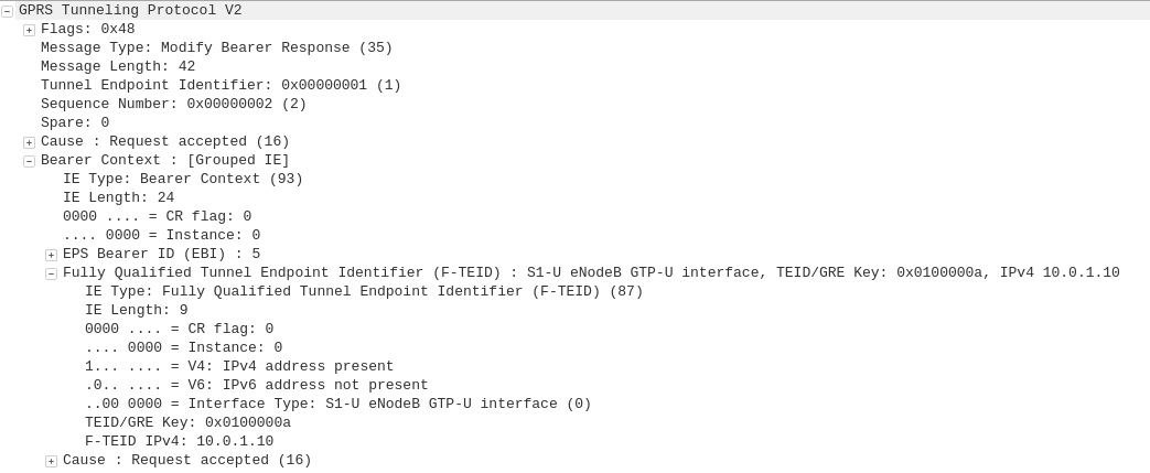
Mapping out TIEDs is typically done by looking at the Create Session Request / Responses, the Create Session Request will have one TIED, while the Create Session Response will have a different TIED, thus giving you your TIED pair.
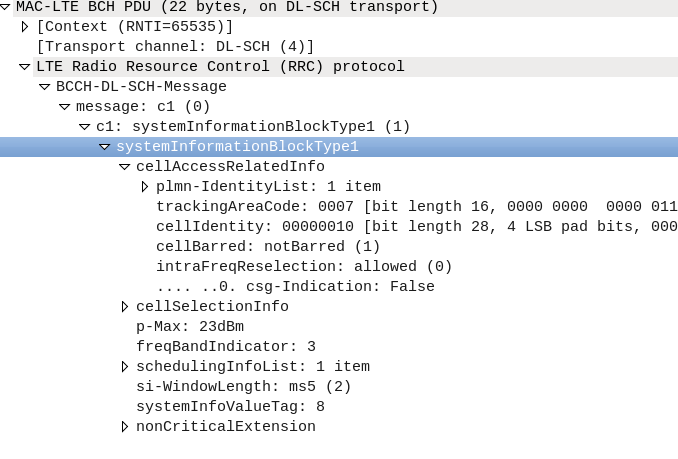
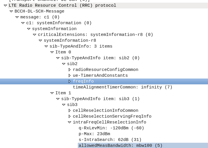
I’ve been experimenting with Inter-RAT & Inter-Frequency handovers recetly, and had an issue where what I thought was configured on the eNB I wasn’t seeing reflected on the UEs.
I understood the Neighbouring Cell reelection parameters are broadcast in the System Information Blocks, but how could I view them?
The answer – srsUE!
I can’t get over how cool the stuff coming out of Software Radio Systems is, but being able to simulate a UE and eNB on SDR hardware is pretty awesome, and also allows you to view low layer traces the vast majority of commercial UEs will never expose to a user.
After running srsUE with the PCAP option I let it scan for networks and find mine. I didn’t actually need to authenticate with the network, just lock to the cell.
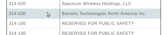
If you’re using BaiCells hardware you may have noticed the new eNBs and USIMs are shipping with the PLMN of MCC 314 / MNC 030.
First thing I do is change the PLMN, but I was curious as to why the change.
It seems 314 / 030 was never assigned to BaiCells to use and when someone picked this up they were forced to change it.
The MCC (Mobile Country Code) part is dictated by the country / geographic area the subscribers’ are in, as defined by ITU, whereas the MNC (Mobile Network Code) allocation is managed by the regional authority and ITU are informed as to what the allocations are and publish in their bulletins.
Well, SIM cards will have a different IMSI / PLMN, but the hardware supports Multi-Operator Core Network which allows one eNB to broadcast multiple PLMNs, so if you update your eNB it can broadcast both!
There’s a lot of layers of signalling in the LTE / EUTRAN attach procedure, but let’s take a look at the UE attach procedure from the Network Perspective.
We won’t touch on the air interface / Uu side of things, just the EPC side of the signaling.
To make life a bit easier I’ve put different signalling messages in different coloured headings:
After a UE establishes a connection with a cell, the first step involved in the attach process is for the UE / subscriber to identify themselves and the network to authenticate them.
The TAI, EUTRAN-CGI and GUMME-ID sections all contain information about the serving network, such the tracking area code, cell global identifier and global MME ID to make up the GUTI.
The NAS part of this request contains key information about our UE and it’s capabilities, most importantly it includes the IMSI or TMSI of the subscriber, but also includes important information such as SRVCC support, different bands and RAN technologies it supports, codecs, but most importantly, the identity of the subscriber.
If this is a new subscriber to the network, the IMSI is sent as the subscriber identity, however wherever possible sending the IMSI is avoided, so if the subscriber has connected to the network recently, the M-TMSI is used instead of the IMSI, and the MME has a record of which M-TMSI to IMSI mapping it’s allocated.
Diameter: Authentication Information Request
MME to HSS
The MME does not have a subscriber database or information on the Crypto side of things, instead this functionality is offloaded to the HSS.
I’ve gone on and on about LTE UE/Subscriber authentication, so I won’t go into the details as to how this mechanism works, but the MME will send a Authentication-Information Request via Diameter to the HSS with the Username set to the Subscriber’s IMSI.
Diameter: Authentication Information Response
HSS to MME
Assuming the subscriber exists in the HSS, a Authentication-Information Answer will be sent back from the HSS via Diameter to the MME, containing the authentication vectors to send to the UE / subscriber.
Now the MME has the Authentication vectors for that UE / Subscriber it sends back a DownlinkNASTransport, Authentication response, with the NAS section populated with the RAND and AUTN values generated by the HSS in the Authentication-Information Answer.
The Subscriber / UE’s USIM looks at the AUTN value and RAND to authenticate the network, and then calculates it’s response (RES) from the RAND value to provide a RES to send back to the network.
S1AP: UplinkNASTransport, Authentication response
eNB to MME
The subscriber authenticates the network based on the sent values, and if the USIM is happy that the network identity has been verified, it generates a RES (response) value which is sent in the UplinkNASTransport, Authentication response.
The MME compares the RES sent Subscriber / UE’s USIM against the one sent by the MME in the Authentication-Information Answer (the XRES – Expected RES).
If the two match then the subscriber is authenticated.
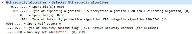
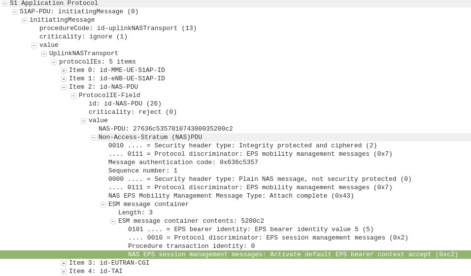
The DownlinkNASTransport, Security mode command is then sent by the MME to the UE to activate the ciphering and integrity protection required by the network, as set in the NAS Security Algorithms section;
The MME and the UE/Subscriber are able to derive the Ciphering Key (CK) and Integrity Key (IK) from the sent crypto variables earlier, and now both know them.
S1AP: UplinkNASTransport, Security mode complete
eNB to MME
After the UE / Subscriber has derived the Ciphering Key (CK) and Integrity Key (IK) from the sent crypto variables earlier, it can put them into place as required by the NAS Security algorithms sent in the Security mode command request.
It indicates this is completed by sending the UplinkNASTransport, Security mode complete.
At this stage the authentication of the subscriber is done, and a default bearer must be established.
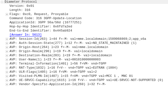
Diameter: Update Location Request
MME to HSS
Once the Security mode has been completed the MME signals to the HSS the Subscriber’s presence on the network and requests their Subscription-Data from the HSS.
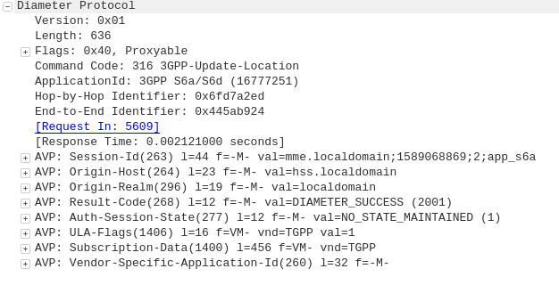
Diameter: Update Location Answer
HSS to MME
The ULA response contains the Subscription Data used to define the data service provided to the subscriber, including the AMBR (Aggregate Maximum Bit Rate), list of valid APNs and TAU Timer.
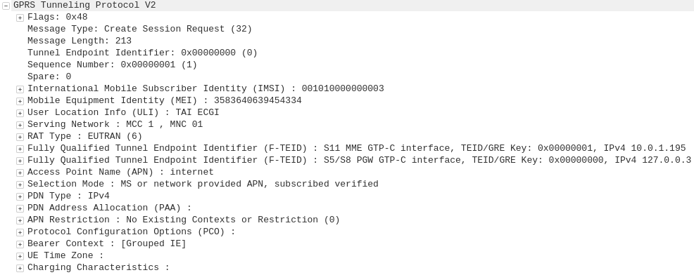
GTP-C: Create Session Request
MME to S-GW
The MME transfers the responsibility of setting up the data bearers to the S-GW in the form of the Create Session Request.
This includes the Tunnel Endpoint Identifier (TEID) to be assigned for this UE’s PDN.
The S-GW looks at the request and forwards it onto a P-GW for IP address assignment and access to the outside world.
GTP-C: Create Session Request
S-GW to P-GW
The S-GW sends a Create Session Request to the P-GW to setup a path to the outside world.
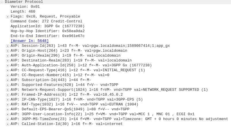
Diameter: Credit Control Request
P-GW to PCRF
To ensure the subscriber is in a state to establish a new PDN connection (not out of credit etc), a Credit Control Request is sent to the HSS.
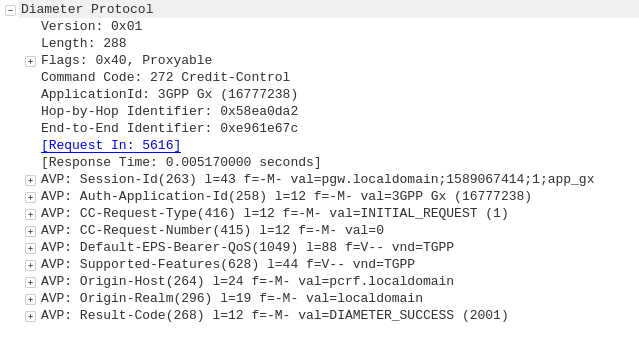
Diameter: Credit Control Answer
PCRF to P-GW
Assuming the Subscriber has adequate credit for this, a Credit Control Answer is sent and the P-GW and continue the PDN setup for the subscriber.
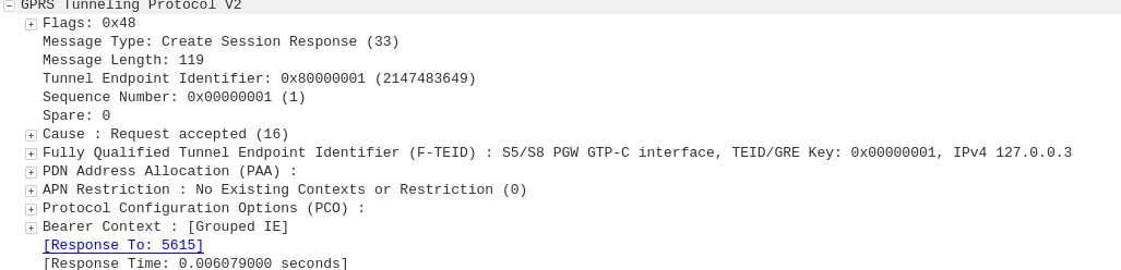
GTP-C: Create Session Response
P-GW to S-GW
The P-GW sends back a Create Session Response, containing the IP address allocated to this PDN (Framed-IP-Address).
GTP-C: Create Session Response
S-GW to MME
The S-GW slightly changes and then relays the Create Session Response back to the MME,
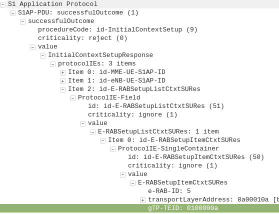
This message is sent to inform the eNB of the details of the PDN connection to be setup, ie AMBR, tracking area list, APN and Protocol Configuration Options,
This contains the Tunnel Endpoint Identifier (TEID) for this PDN to identify the GTP packets.
These posts focus on the use of Diameter and SIP in an IMS / VoLTE context, however these practices can be equally applied to other networks.
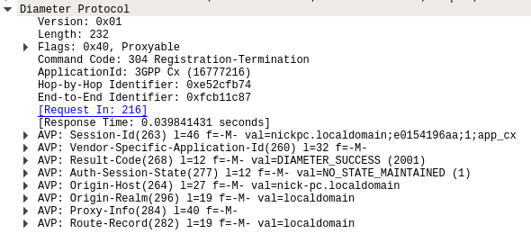
The Registration-Termination Request / Answer allow a Diameter Client (S-CSCF) to indicate to the HSS (Diameter Server) that it is no longer serving that user and the registration has been terminated.
Basics:
The RFC’s definition is actually pretty succinct as to the function of the Server-Assignment Request/Answer:
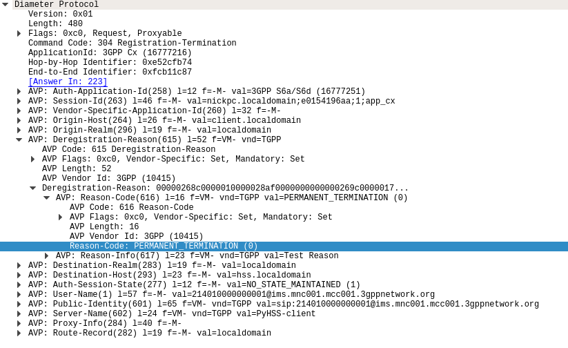
The Registration-Termination-Request is sent by a Diameter Multimedia server to a Diameter Multimedia client in order to request the de-registration of a user.
Reference: TS 29.229
The Registration-Termination-Request commands are sent by a S-CSCF to indicate to the Diameter server that it is no longer serving a specific subscriber, and therefore this subscriber is now unregistered.
There are a variety of reasons for this, such as PERMANENT_TERMINATION, NEW_SIP_SERVER_ASSIGNED and SIP_SERVER_CHANGE.
The Diameter Server (HSS) will typically send the Diameter Client (S-CSCF) a Registration-Termination-Answer in response to indicate it has updated it’s internal database and will no longer consider the user to be registered at that S-CSCF.
Packet Capture
I’ve included a packet capture of these Diameter Commands from my lab network which you can find below.
These posts focus on the use of Diameter and SIP in an IMS / VoLTE context, however these practices can be equally applied to other networks.
The Diameter User-Authorization-Request and User-Authorization-Answer commands are used as the first line of authorization of a user and to determine which Serving-CSCF to forward a request to.
Basics
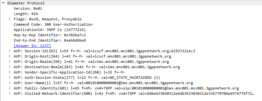
When a SIP Proxy (I-CSCF) receives an incoming SIP REGISTER request, it sends a User-Authorization-Request to a Diameter server to confirm if the user exists on the network, and which S-CSCF to forward the request to.
When the Diameter server receives the User-Authorization-Request it looks at the User-Name (1) AVP to determine if the Domain / Realm is served by the Diameter server and the User specified exists.
Assuming the user & domain are valid, the Diameter server sends back a User-Authorization-Answer, containing a Server-Capabilities (603) AVP with the Server-Name of the S-CSCF the user will be served by.
I always find looking at the packets puts everything in context, so here’s a packet capture of both the User-Authorization-Request and the User-Authorization-Answer.
Wireshark display of User-Authorization-Request packet
Wireshark display of User-Authorization-Answer packet
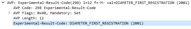
First Registration
If this is the first time this Username / Domain combination (Referred to in the RFC as an AOR – Address of Record) is seen by the Diameter server in the User-Authorization-Request it will allocate a S-CSCF address for the subscriber to use from it’s pool / internal logic.
The Diameter server will store the S-CSCF it allocated to that Username / Domain combination (AoR) for subsequent requests to ensure they’re routed to the same S-CSCF.
The Diameter server indicates this is the first time it’s seen it by adding the DIAMETER_FIRST_REGISTRATION (2001) AVP to the User-Authorization-Answer.
Subsequent Registration
If the Diameter server receives another User-Authorization-Request for the same Username / Domain (AoR) it has served before, the Diameter server returns the same S-CSCF address as it did in the first User-Authorization-Answer.
It indicates this is a subsequent registration in much the same way the first registration is indicated, by adding an DIAMETER_SUBSEQUENT_REGISTRATION (2002) AVP to the User-Authorization-Answer.
User-Authorization-Type (623) AVP
An optional User-Authorization-Type (623) AVP is available to indicate the reason for the User-Authorization-Request. The possible values / reasons are:
Creating / Updating / Renewing a SIP Registration (REGISTRATION (0))
Establishing Server Capabilities & Registering (CAPABILITIES (2))
Terminating a SIP Registration (DEREGISTRATION (1))
If the User-Authorization-Type is set to DEREGISTRATION (1) then the Diameter server returns the S-CSCF address in the User-Authorization-Answer and then removes the S-SCSF address it had associated with the AoR from it’s own records.
These posts focus on the use of Diameter and SIP in an IMS / VoLTE context, however these practices can be equally applied to other networks.
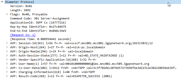
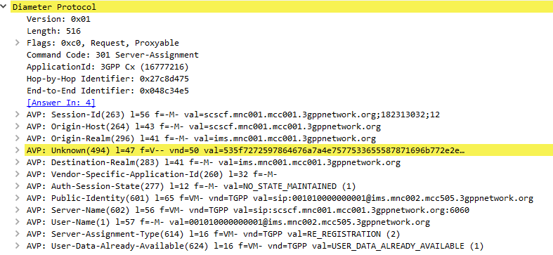
The Server-Assignment-Request/Answer commands are used so a SIP Server can indicate to a Diameter server that it is serving a subscriber and pull the profile information of the subscriber.
Basics:
The RFC’s definition is actually pretty succinct as to the function of the Server-Assignment Request/Answer:
The main functions of the Diameter SAR command are to inform the Diameter server of the URI of the SIP server allocated to the user, and to store or clear it from the Diameter server.
Additionally, the Diameter client can request to download the user profile or part of it.
The Server-Assignment-Request/Answer commands are sent by a S-CSCF to indicate to the Diameter server that it is now serving a specific subscriber, (This information can then be queried using the Location-Info-Request commands) and get the subscriber’s profile, which contains the details and identities of the subscriber.
Typically upon completion of a successful SIP REGISTER dialog (Multimedia-Authentication Request), the SIP Server (S-CSCF) sends the Diameter server a Server-Assignment-Request containing the SIP Username / Domain (referred to as an Address on Record (SIP-AOR) in the RFC) and the SIP Server (S-CSCF)’s SIP-Server-URI.
The Diameter server looks at the SIP-AOR and ensures there are not currently any active SIP-Server-URIs associated with that AoR. If there are not any currently active it then stores the SIP-AOR and the SIP-Server-URI of the SIP Server (S-CSCF) serving that user & sends back a Server-Assignment-Answer.
For most request the Subscriber’s profile is also transfered to the S-SCSF in the Server-Assignment-Answer command.
SIP-Server-Assignment-Type AVP
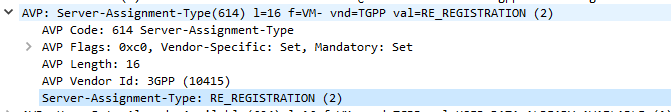
The same Server-Assignment-Request command can be used to register, re-register, remove registration bindings and pull the user profile, through the information in the SIP-Server-Assignment-Type AVP (375),
Common values are:
NO_ASSIGNMENT (0) – Used to pull just the user profile
The Cx-User-Data profile contains the subscriber’s profile from the Diameter server in an XML formatted dataset, that is contained as part of the Server-Assignment-Answer in the Cx-User-Data AVP (606).
The profile his tells the S-CSCF what services are offered to the subscriber, such as the allowed SIP Methods (ie INVITE, MESSAGE, etc), and how to handle calls to the user when the user is not registered (ie send calls to voicemail if the user is not there).
There’s a lot to cover on the user profile which we’ll touch on in a later post.
These posts focus on the use of Diameter and SIP in an IMS / VoLTE context, however these practices can be equally applied to other networks.
The Location-Information-Request/Answer commands are used so a SIP Server query a Diameter to find which P-CSCF a Subscriber is being served by
Basics:
The RFC’s definition is actually pretty succinct as to the function of the Server-Assignment Request/Answer:
The Location-Info-Request is sent by a Diameter Multimedia client to a Diameter Multimedia server in order to request name of the server that is currently serving the user.Reference: 29.229-
The Location-Info-Request is sent by a Diameter Multimedia client to a Diameter Multimedia server in order to request name of the server that is currently serving the user.
Reference: TS 29.229
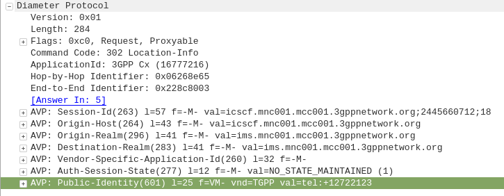
The Location-Info-Request commands is sent by an I-CSCF to the HSS to find out from the Diameter server the FQDN of the S-CSCF serving that user.
The Public-Identity AVP (601) contains the Public Identity of the user being sought.
Here you can see the I-CSCF querying the HSS via Diameter to find the S-CSCF for public identity 12722123
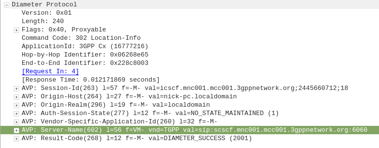
The Diameter server sends back the Location-Info-Response containing the Server-Name AVP (602) with the FQDN of the S-CSCF.
Packet Capture
I’ve included a packet capture of these Diameter Commands from my lab network which you can find below.