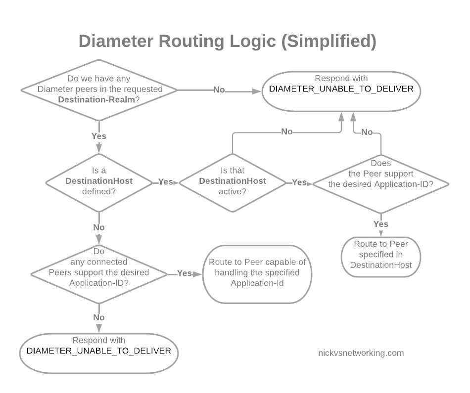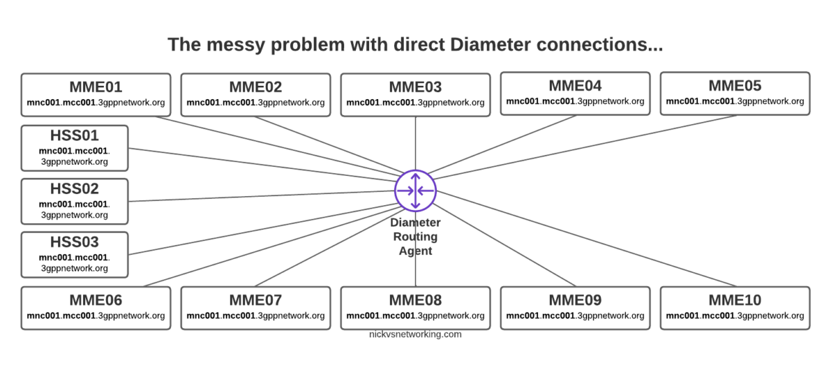
Way back in part 2 we discussed the basic routing logic a DRA handles, but what if we want to do something a bit outside of the box in terms of how we route?
For me, one of the most useful use cases for a DRA is to route traffic based on IMSI / Username.
This means I can route all the traffic for MVNO X to MVNO X’s HSS, or for staging / test subs to the test HSS enviroment.
FreeDiameter has a bunch of built in logic that handles routing based on a weight, but we can override this, using the rt_default module.
In our last post we had this module commented out, but let’s uncomment it and start playing with it:
#Basic Diameter config for this box
Identity = "dra.mnc001.mcc001.3gppnetwork.org";
Realm = "mnc001.mcc001.3gppnetwork.org";
Port = 3868;

LoadExtension = "dbg_msg_dumps.fdx" : "0x8888";
LoadExtension = "rt_redirect.fdx":"0x0080";
LoadExtension = "rt_default.fdx":"rt_default.conf";

TLS_Cred = "/etc/freeDiameter/cert.pem", "/etc/freeDiameter/privkey.pem";
TLS_CA = "/etc/freeDiameter/cert.pem";
TLS_DH_File = "/etc/freeDiameter/dh.pem";

ConnectPeer = "mme01.mnc001.mcc001.3gppnetwork.org" { ConnectTo = "10.98.0.10"; No_TLS; };
ConnectPeer = "hss01" { ConnectTo = "10.0.1.252"; No_TLS; Port = 3868; Realm = "mnc001.mcc001.3gppnetwork.org";};
ConnectPeer = "hss02" { ConnectTo = "10.0.1.253"; No_TLS; Port = 3868; Realm = "mnc001.mcc001.3gppnetwork.org";};
ConnectPeer = "hss-mvno-x" { ConnectTo = "10.98.0.22"; No_TLS; Port = 3868; Realm = "mnc001.mcc001.3gppnetwork.org";};
ConnectPeer = "hss-lab" { ConnectTo = "10.0.2.2"; No_TLS; Port = 3868; Realm = "mnc001.mcc001.3gppnetwork.org";};
In the above code we’ve uncommented rt_default and rt_redirect.
You’ll notice that rt_default references a config file, so we’ll create a new file in our /etc/freeDiameter directory called rt_default.conf, and this is where the magic will happen.
A few points before we get started:
- This overrides the default routing priorities, but in order for a peer to be selected, it has to be in an Open (active) state
- The peer still has to have advertised support for the requested application in the CER/CEA dialog
- The peers will still need to have all been defined in the freeDiameter.conf file in order to be selected
So with that in mind, and the 5 peers we have defined in our config above (assuming all are connected), let’s look at some rules we can setup using rt_default.
Intro to rt_default Rules
The rt_default.conf file contains a list of rules, each rule has a criteria that if matched, will result in the specified action being taken. The actions all revolve around how to route the traffic.
So what can these criteria match on?
Here’s the options:
| Item to Match | Code |
| Any | * |
| Origin-Host | oh=”STR/REG” |
| Origin-Realm | or=”STR/REG” |
| Destination-Host | dh=”STR/REG” |
| Destination-Realm | dr=”STR/REG” |
| User-Name | un=”STR/REG” |
| Session-Id | si=”STR/REG” |
We can either match based on a string or a regex, for example, if we want to match anything where the Destination-Realm is “mnc001.mcc001.3gppnetwork.org” we’d use something like:
#Low score to HSS02
dr="mnc001.mcc001.3gppnetwork.org" : dh="hss02" += -70 ;
Now you’ll notice there is some stuff after this, let’s look at that.
We’re matching anything where the destination-host is set to hss02 (that’s the bit before the colon), but what’s the bit after that?
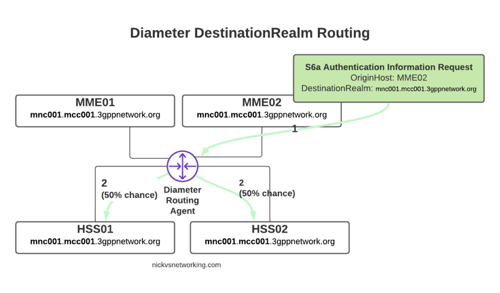
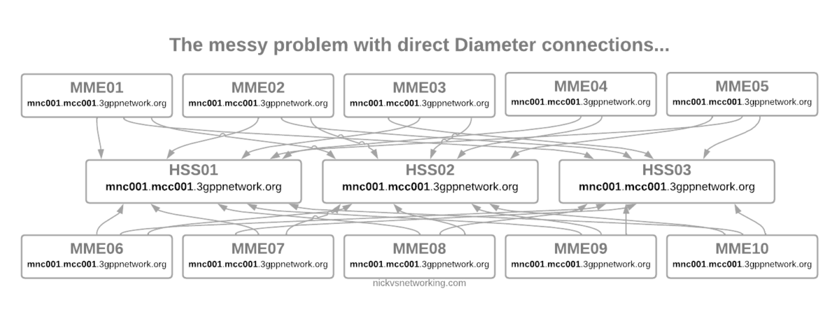
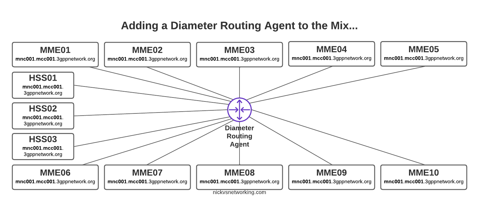
Well if we imagine that all our Diameter peers are up, when a message comes in with Destination-Realm “mnc001.mcc001.3gppnetwork.org”, looking for an HSS, then in our example setup, we have 4 HHS instances to choose from (assuming they’re all online).
In default Diameter routing, all of these peers are in the same realm, and as they’re all HSS instances, they all support the same applications – Our request could go to any of them.
But what we set in the above example is simply the following:
If the Destination-Realm is set to mnc001.mcc001.3gppnetwork.org, then set the priority for routing to hss02 to the lowest possible value.
So that leaves the 3 other Diameter peers with a higher score than HSS02, so HSS02 won’t be used.
Let’s steer this a little more,
Let’s specify that we want to use HSS01 to handle all the requests (if it’s available), we can do that by adding a rule like this:
#Low score to HSS02
dr="mnc001.mcc001.3gppnetwork.org" : dh="hss02" += -70 ;
#High score to HSS01
dr="mnc001.mcc001.3gppnetwork.org" : dh="hss01" += 100 ;
But what if we want to route to hss-lab if the IMSI matches a specific value, well we can do that too.
#Low score to HSS02
dr="mnc001.mcc001.3gppnetwork.org" : dh="hss02" += -70 ;
#High score to HSS01
dr="mnc001.mcc001.3gppnetwork.org" : dh="hss01" += 100 ;
#Route traffic for IMSI to Lab HSS
un="001019999999999999" : dh="hss-lab" += 200 ;
Now that we’ve set an entry with a higher score than hss01 that will be matched if the username (IMSI) equals 001019999999999999, the traffic will get routed to hss-lab.
But that’s a whole IMSI, what if we want to match only part of a field?
Well, we can use regex in the Criteria as well, so let’s look at using some Regex, let’s say for example all our MVNO SIMs start with 001012xxxxxxx, let’s setup a rule to match that, and route to the MVNO HSS with a higher priority than our normal HSS:
#Low score to HSS02
dr="mnc001.mcc001.3gppnetwork.org" : dh="hss02" += -70 ;
#High score to HSS01
dr="mnc001.mcc001.3gppnetwork.org" : dh="hss01" += 100 ;
#Route traffic for IMSI to Lab HSS
un="001019999999999999" : dh="hss-lab" += 200 ;
#Route traffic where IMSI starts with 001012 to MVNO HSS
un=["^001012.*"] : dh="hss-mvno-x" += 200 ;
Let’s imagine that down the line we introduce HSS03 and HSS04, and we only want to use HSS01 if HSS03 and HSS04 are unavailable, and only to use HSS02 no other HSSes are available, and we want to split the traffic 50/50 across HSS03 and HSS04.
Firstly we’d need to add HSS03 and HSS04 to our FreeDiameter.conf file:
...
ConnectPeer = "hss02" { ConnectTo = "10.0.1.253"; No_TLS; Port = 3868; Realm = "mnc001.mcc001.3gppnetwork.org";};
ConnectPeer = "hss03" { ConnectTo = "10.0.3.3"; No_TLS; Port = 3868; Realm = "mnc001.mcc001.3gppnetwork.org";};
ConnectPeer = "hss04" { ConnectTo = "10.0.4.4"; No_TLS; Port = 3868; Realm = "mnc001.mcc001.3gppnetwork.org";};
...
Then in our rt_default.conf we’d need to tweak our scores again:
#Low score to HSS02
dr="mnc001.mcc001.3gppnetwork.org" : dh="hss02" += 10 ;
#Medium score to HSS01
dr="mnc001.mcc001.3gppnetwork.org" : dh="hss01" += 20 ;
#Route traffic for IMSI to Lab HSS
un="001019999999999999" : dh="hss-lab" += 200 ;
#Route traffic where IMSI starts with 001012 to MVNO HSS
un=["^001012.*"] : dh="hss-mvno-x" += 200 ;
#High Score for HSS03 and HSS04
dr="mnc001.mcc001.3gppnetwork.org" : dh="hss02" += 100 ;
dr="mnc001.mcc001.3gppnetwork.org" : dh="hss04" += 100 ;
One quick tip to keep your logic a bit simpler, is that we can set a variety of different values based on keywords (listed below) rather than on a weight/score:
| Behaviour | Name | Score |
| Do not deliver to peer (set lowest priority) | NO_DELIVERY | -70 |
| The peer is a default route for all messages | DEFAULT | 5 |
| The peer is a default route for this realm | DEFAULT_REALM | 10 |
| REALM | 15 | |
| Route to the specified Host with highest priority | FINALDEST | 100 |
In our next post we’ll look at using FreeDiameter based DRA in roaming scenarios where we route messages across Diameter Realms.