If you’re using BaiCells hardware you may have noticed the new eNBs and USIMs are shipping with the PLMN of MCC 314 / MNC 030.
First thing I do is change the PLMN, but I was curious as to why the change.
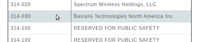
It seems 314 / 030 was never assigned to BaiCells to use and when someone picked this up they were forced to change it.
The MCC (Mobile Country Code) part is dictated by the country / geographic area the subscribers’ are in, as defined by ITU, whereas the MNC (Mobile Network Code) allocation is managed by the regional authority and ITU are informed as to what the allocations are and publish in their bulletins.
Well, SIM cards will have a different IMSI / PLMN, but the hardware supports Multi-Operator Core Network which allows one eNB to broadcast multiple PLMNs, so if you update your eNB it can broadcast both!
There’s a lot of layers of signalling in the LTE / EUTRAN attach procedure, but let’s take a look at the UE attach procedure from the Network Perspective.
We won’t touch on the air interface / Uu side of things, just the EPC side of the signaling.
To make life a bit easier I’ve put different signalling messages in different coloured headings:
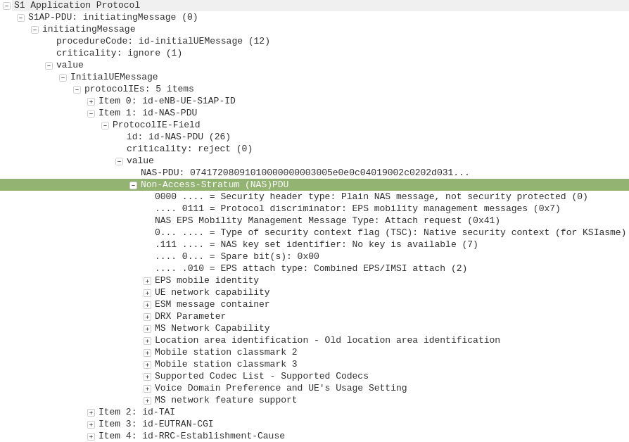
After a UE establishes a connection with a cell, the first step involved in the attach process is for the UE / subscriber to identify themselves and the network to authenticate them.
The TAI, EUTRAN-CGI and GUMME-ID sections all contain information about the serving network, such the tracking area code, cell global identifier and global MME ID to make up the GUTI.
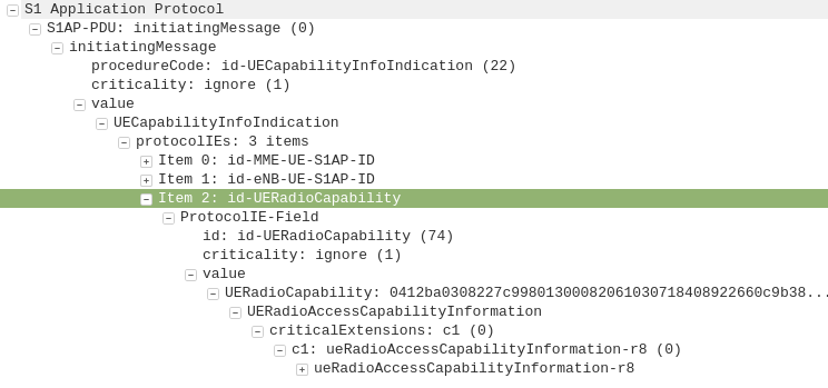
The NAS part of this request contains key information about our UE and it’s capabilities, most importantly it includes the IMSI or TMSI of the subscriber, but also includes important information such as SRVCC support, different bands and RAN technologies it supports, codecs, but most importantly, the identity of the subscriber.
If this is a new subscriber to the network, the IMSI is sent as the subscriber identity, however wherever possible sending the IMSI is avoided, so if the subscriber has connected to the network recently, the M-TMSI is used instead of the IMSI, and the MME has a record of which M-TMSI to IMSI mapping it’s allocated.
Diameter: Authentication Information Request
MME to HSS
The MME does not have a subscriber database or information on the Crypto side of things, instead this functionality is offloaded to the HSS.
I’ve gone on and on about LTE UE/Subscriber authentication, so I won’t go into the details as to how this mechanism works, but the MME will send a Authentication-Information Request via Diameter to the HSS with the Username set to the Subscriber’s IMSI.
Diameter: Authentication Information Response
HSS to MME
Assuming the subscriber exists in the HSS, a Authentication-Information Answer will be sent back from the HSS via Diameter to the MME, containing the authentication vectors to send to the UE / subscriber.
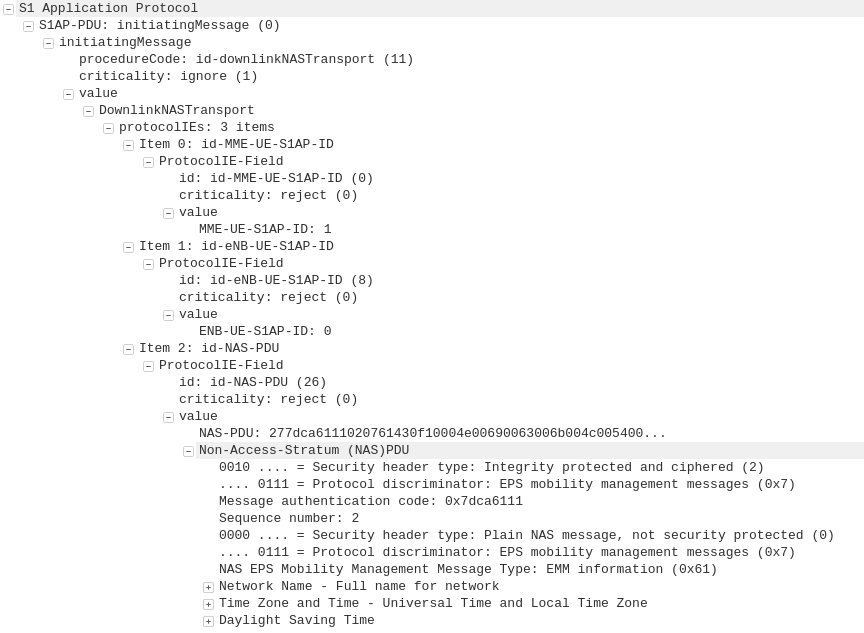
Now the MME has the Authentication vectors for that UE / Subscriber it sends back a DownlinkNASTransport, Authentication response, with the NAS section populated with the RAND and AUTN values generated by the HSS in the Authentication-Information Answer.
The Subscriber / UE’s USIM looks at the AUTN value and RAND to authenticate the network, and then calculates it’s response (RES) from the RAND value to provide a RES to send back to the network.
S1AP: UplinkNASTransport, Authentication response
eNB to MME
The subscriber authenticates the network based on the sent values, and if the USIM is happy that the network identity has been verified, it generates a RES (response) value which is sent in the UplinkNASTransport, Authentication response.
The MME compares the RES sent Subscriber / UE’s USIM against the one sent by the MME in the Authentication-Information Answer (the XRES – Expected RES).
If the two match then the subscriber is authenticated.
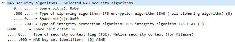
The DownlinkNASTransport, Security mode command is then sent by the MME to the UE to activate the ciphering and integrity protection required by the network, as set in the NAS Security Algorithms section;
The MME and the UE/Subscriber are able to derive the Ciphering Key (CK) and Integrity Key (IK) from the sent crypto variables earlier, and now both know them.
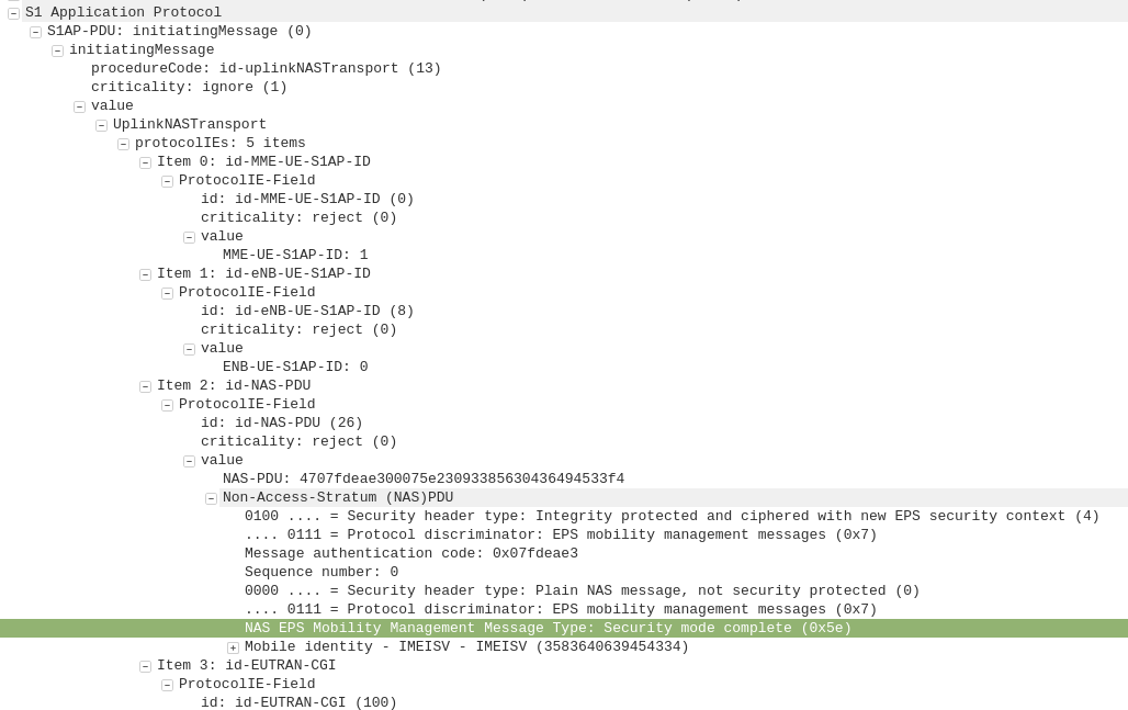
S1AP: UplinkNASTransport, Security mode complete
eNB to MME
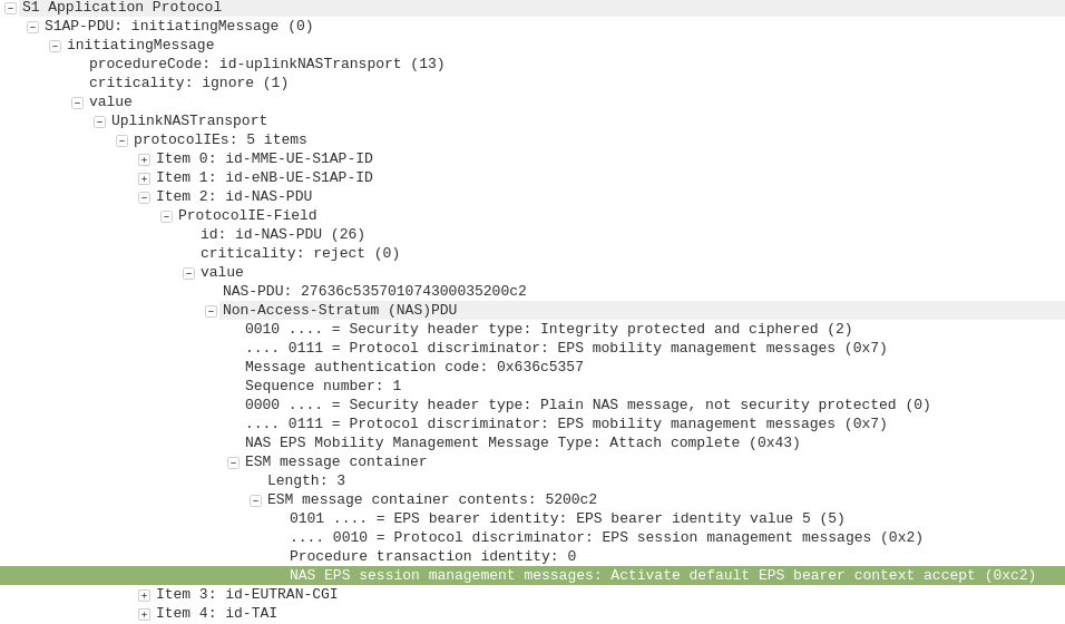
After the UE / Subscriber has derived the Ciphering Key (CK) and Integrity Key (IK) from the sent crypto variables earlier, it can put them into place as required by the NAS Security algorithms sent in the Security mode command request.
It indicates this is completed by sending the UplinkNASTransport, Security mode complete.
At this stage the authentication of the subscriber is done, and a default bearer must be established.
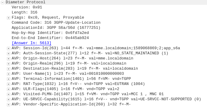
Diameter: Update Location Request
MME to HSS
Once the Security mode has been completed the MME signals to the HSS the Subscriber’s presence on the network and requests their Subscription-Data from the HSS.
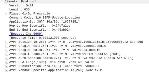
Diameter: Update Location Answer
HSS to MME
The ULA response contains the Subscription Data used to define the data service provided to the subscriber, including the AMBR (Aggregate Maximum Bit Rate), list of valid APNs and TAU Timer.
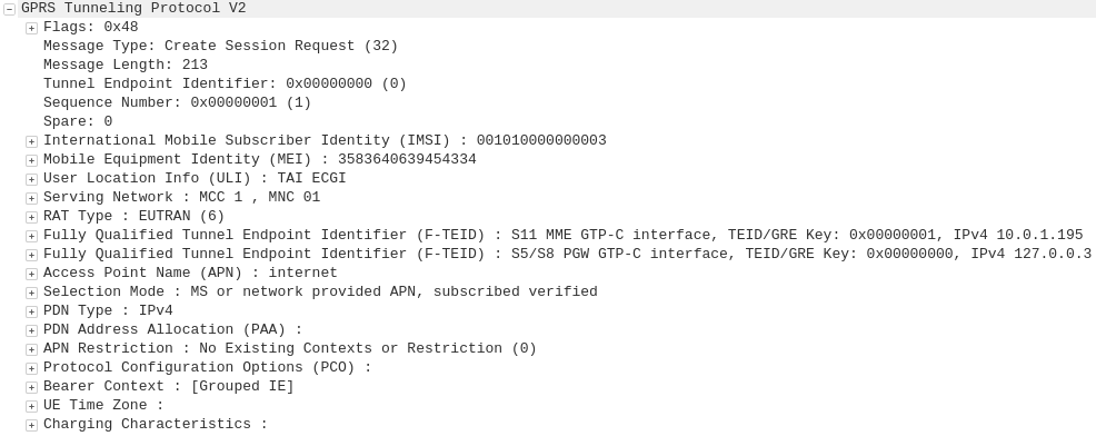
GTP-C: Create Session Request
MME to S-GW
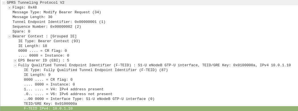
The MME transfers the responsibility of setting up the data bearers to the S-GW in the form of the Create Session Request.
This includes the Tunnel Endpoint Identifier (TEID) to be assigned for this UE’s PDN.
The S-GW looks at the request and forwards it onto a P-GW for IP address assignment and access to the outside world.
GTP-C: Create Session Request
S-GW to P-GW
The S-GW sends a Create Session Request to the P-GW to setup a path to the outside world.
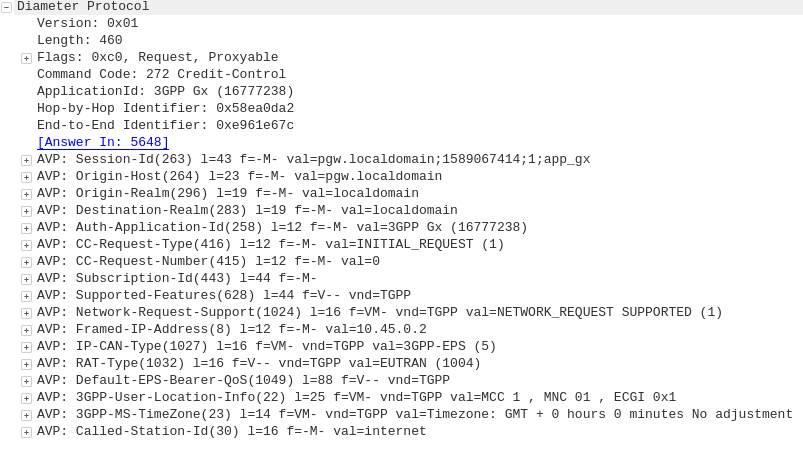
Diameter: Credit Control Request
P-GW to PCRF
To ensure the subscriber is in a state to establish a new PDN connection (not out of credit etc), a Credit Control Request is sent to the HSS.
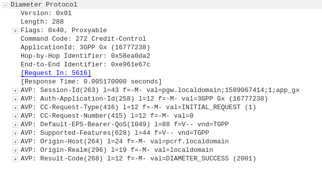
Diameter: Credit Control Answer
PCRF to P-GW
Assuming the Subscriber has adequate credit for this, a Credit Control Answer is sent and the P-GW and continue the PDN setup for the subscriber.
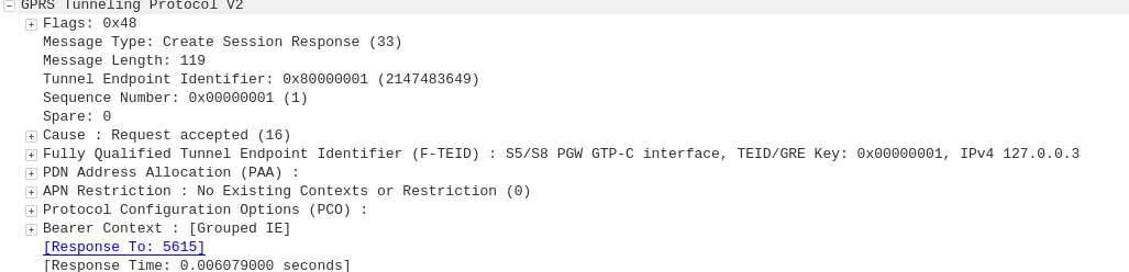
GTP-C: Create Session Response
P-GW to S-GW
The P-GW sends back a Create Session Response, containing the IP address allocated to this PDN (Framed-IP-Address).
GTP-C: Create Session Response
S-GW to MME
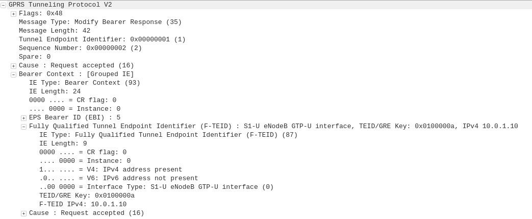
The S-GW slightly changes and then relays the Create Session Response back to the MME,
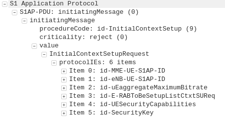
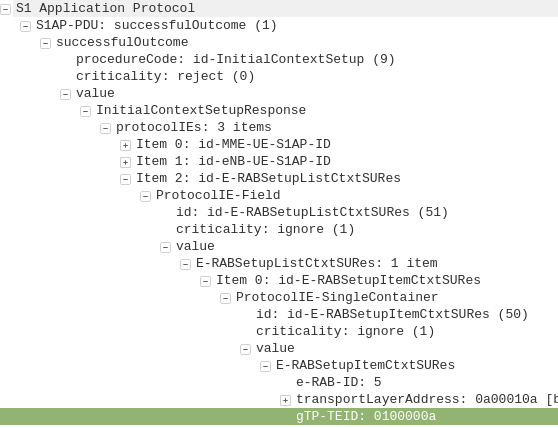
This message is sent to inform the eNB of the details of the PDN connection to be setup, ie AMBR, tracking area list, APN and Protocol Configuration Options,
This contains the Tunnel Endpoint Identifier (TEID) for this PDN to identify the GTP packets.
These posts focus on the use of Diameter and SIP in an IMS / VoLTE context, however these practices can be equally applied to other networks.
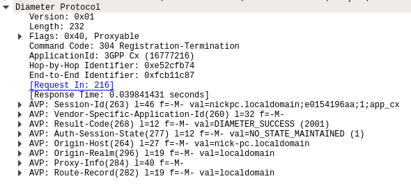
The Registration-Termination Request / Answer allow a Diameter Client (S-CSCF) to indicate to the HSS (Diameter Server) that it is no longer serving that user and the registration has been terminated.
Basics:
The RFC’s definition is actually pretty succinct as to the function of the Server-Assignment Request/Answer:
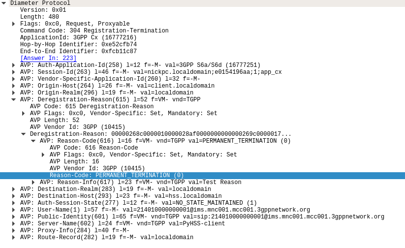
The Registration-Termination-Request is sent by a Diameter Multimedia server to a Diameter Multimedia client in order to request the de-registration of a user.
Reference: TS 29.229
The Registration-Termination-Request commands are sent by a S-CSCF to indicate to the Diameter server that it is no longer serving a specific subscriber, and therefore this subscriber is now unregistered.
There are a variety of reasons for this, such as PERMANENT_TERMINATION, NEW_SIP_SERVER_ASSIGNED and SIP_SERVER_CHANGE.
The Diameter Server (HSS) will typically send the Diameter Client (S-CSCF) a Registration-Termination-Answer in response to indicate it has updated it’s internal database and will no longer consider the user to be registered at that S-CSCF.
Packet Capture
I’ve included a packet capture of these Diameter Commands from my lab network which you can find below.
These posts focus on the use of Diameter and SIP in an IMS / VoLTE context, however these practices can be equally applied to other networks.
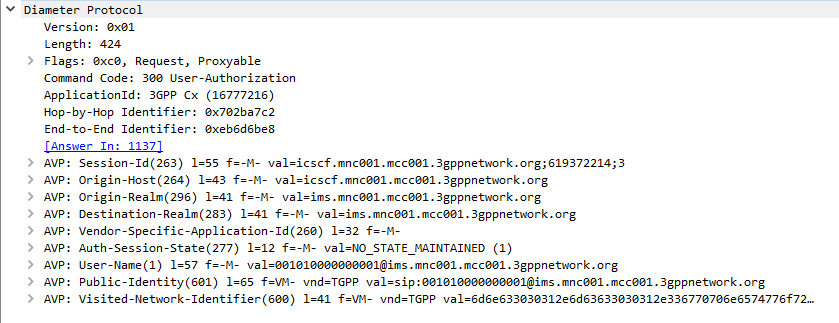
The Diameter User-Authorization-Request and User-Authorization-Answer commands are used as the first line of authorization of a user and to determine which Serving-CSCF to forward a request to.
Basics
When a SIP Proxy (I-CSCF) receives an incoming SIP REGISTER request, it sends a User-Authorization-Request to a Diameter server to confirm if the user exists on the network, and which S-CSCF to forward the request to.
When the Diameter server receives the User-Authorization-Request it looks at the User-Name (1) AVP to determine if the Domain / Realm is served by the Diameter server and the User specified exists.
Assuming the user & domain are valid, the Diameter server sends back a User-Authorization-Answer, containing a Server-Capabilities (603) AVP with the Server-Name of the S-CSCF the user will be served by.
I always find looking at the packets puts everything in context, so here’s a packet capture of both the User-Authorization-Request and the User-Authorization-Answer.
Wireshark display of User-Authorization-Request packet
Wireshark display of User-Authorization-Answer packet
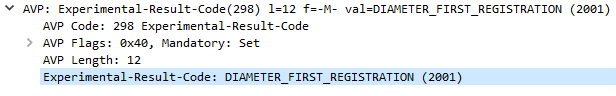
First Registration
If this is the first time this Username / Domain combination (Referred to in the RFC as an AOR – Address of Record) is seen by the Diameter server in the User-Authorization-Request it will allocate a S-CSCF address for the subscriber to use from it’s pool / internal logic.
The Diameter server will store the S-CSCF it allocated to that Username / Domain combination (AoR) for subsequent requests to ensure they’re routed to the same S-CSCF.
The Diameter server indicates this is the first time it’s seen it by adding the DIAMETER_FIRST_REGISTRATION (2001) AVP to the User-Authorization-Answer.
Subsequent Registration
If the Diameter server receives another User-Authorization-Request for the same Username / Domain (AoR) it has served before, the Diameter server returns the same S-CSCF address as it did in the first User-Authorization-Answer.
It indicates this is a subsequent registration in much the same way the first registration is indicated, by adding an DIAMETER_SUBSEQUENT_REGISTRATION (2002) AVP to the User-Authorization-Answer.
User-Authorization-Type (623) AVP
An optional User-Authorization-Type (623) AVP is available to indicate the reason for the User-Authorization-Request. The possible values / reasons are:
Creating / Updating / Renewing a SIP Registration (REGISTRATION (0))
Establishing Server Capabilities & Registering (CAPABILITIES (2))
Terminating a SIP Registration (DEREGISTRATION (1))
If the User-Authorization-Type is set to DEREGISTRATION (1) then the Diameter server returns the S-CSCF address in the User-Authorization-Answer and then removes the S-SCSF address it had associated with the AoR from it’s own records.
These posts focus on the use of Diameter and SIP in an IMS / VoLTE context, however these practices can be equally applied to other networks.
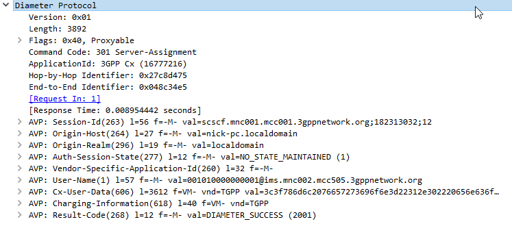
The Server-Assignment-Request/Answer commands are used so a SIP Server can indicate to a Diameter server that it is serving a subscriber and pull the profile information of the subscriber.
Basics:
The RFC’s definition is actually pretty succinct as to the function of the Server-Assignment Request/Answer:
The main functions of the Diameter SAR command are to inform the Diameter server of the URI of the SIP server allocated to the user, and to store or clear it from the Diameter server.
Additionally, the Diameter client can request to download the user profile or part of it.
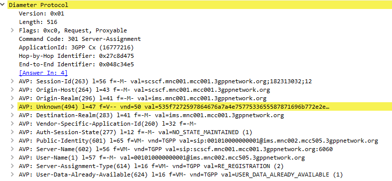
The Server-Assignment-Request/Answer commands are sent by a S-CSCF to indicate to the Diameter server that it is now serving a specific subscriber, (This information can then be queried using the Location-Info-Request commands) and get the subscriber’s profile, which contains the details and identities of the subscriber.
Typically upon completion of a successful SIP REGISTER dialog (Multimedia-Authentication Request), the SIP Server (S-CSCF) sends the Diameter server a Server-Assignment-Request containing the SIP Username / Domain (referred to as an Address on Record (SIP-AOR) in the RFC) and the SIP Server (S-CSCF)’s SIP-Server-URI.
The Diameter server looks at the SIP-AOR and ensures there are not currently any active SIP-Server-URIs associated with that AoR. If there are not any currently active it then stores the SIP-AOR and the SIP-Server-URI of the SIP Server (S-CSCF) serving that user & sends back a Server-Assignment-Answer.
For most request the Subscriber’s profile is also transfered to the S-SCSF in the Server-Assignment-Answer command.
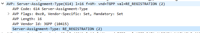
SIP-Server-Assignment-Type AVP
The same Server-Assignment-Request command can be used to register, re-register, remove registration bindings and pull the user profile, through the information in the SIP-Server-Assignment-Type AVP (375),
Common values are:
NO_ASSIGNMENT (0) – Used to pull just the user profile
The Cx-User-Data profile contains the subscriber’s profile from the Diameter server in an XML formatted dataset, that is contained as part of the Server-Assignment-Answer in the Cx-User-Data AVP (606).
The profile his tells the S-CSCF what services are offered to the subscriber, such as the allowed SIP Methods (ie INVITE, MESSAGE, etc), and how to handle calls to the user when the user is not registered (ie send calls to voicemail if the user is not there).
There’s a lot to cover on the user profile which we’ll touch on in a later post.
These posts focus on the use of Diameter and SIP in an IMS / VoLTE context, however these practices can be equally applied to other networks.
The Location-Information-Request/Answer commands are used so a SIP Server query a Diameter to find which P-CSCF a Subscriber is being served by
Basics:
The RFC’s definition is actually pretty succinct as to the function of the Server-Assignment Request/Answer:
The Location-Info-Request is sent by a Diameter Multimedia client to a Diameter Multimedia server in order to request name of the server that is currently serving the user.Reference: 29.229-
The Location-Info-Request is sent by a Diameter Multimedia client to a Diameter Multimedia server in order to request name of the server that is currently serving the user.
Reference: TS 29.229
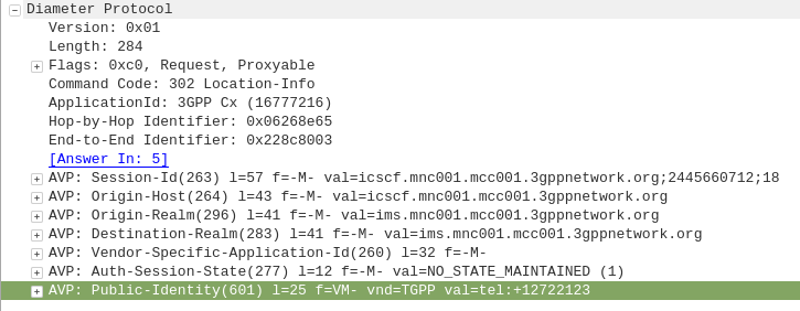
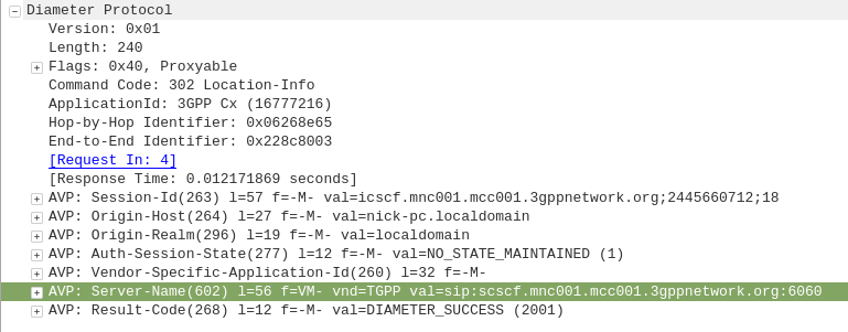
The Location-Info-Request commands is sent by an I-CSCF to the HSS to find out from the Diameter server the FQDN of the S-CSCF serving that user.
The Public-Identity AVP (601) contains the Public Identity of the user being sought.
Here you can see the I-CSCF querying the HSS via Diameter to find the S-CSCF for public identity 12722123
The Diameter server sends back the Location-Info-Response containing the Server-Name AVP (602) with the FQDN of the S-CSCF.
Packet Capture
I’ve included a packet capture of these Diameter Commands from my lab network which you can find below.
These posts focus on the use of Diameter and SIP in an IMS / VoLTE context, however these practices can be equally applied to other networks.
The Multimedia-Authentication-Request/Answer commands are used to Authenticate subscribers / UAs using a variety of mechanisms such as straight MD5 and AKAv1-MD5.
Basics:
When a SIP Server (S-CSCF) receives a SIP INVITE, SIP REGISTER or any other SIP request, it needs a way to Authenticate the Subscriber / UA who sent the request.
We’ve already looked at the Diameter User-Authorization-Request/Answer commands used to Authorize a user for access, but the Multimedia-Authentication-Request / Multimedia-Authentication-Answer it used to authenticate the user.
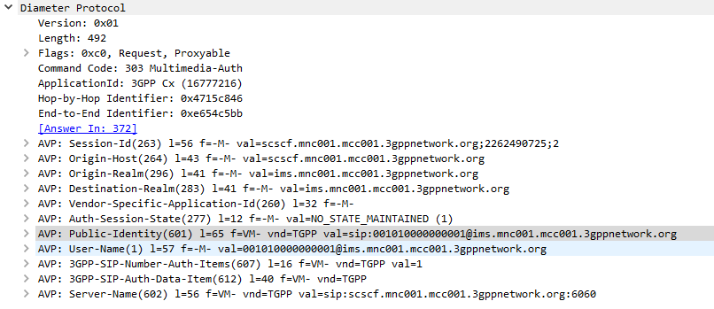
The SIP Server (S-CSCF) sends a Multimedia-Authentication-Request to the Diameter server, containing the Username of the user attempting to authenticate and their Public Identity.
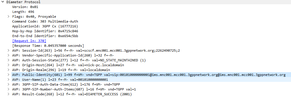
The Diameter server generates “Authentication Vectors” – these are Precomputed cryptographic challenges to challenge the user, and the correct (“expected”) responses to the challenges. The Diameter puts these Authentication Vectors in the 3GPP-SIP-Auth-Data (612) AVP, and sends them back to the SIP server in the Multimedia-Authentication-Answer command.
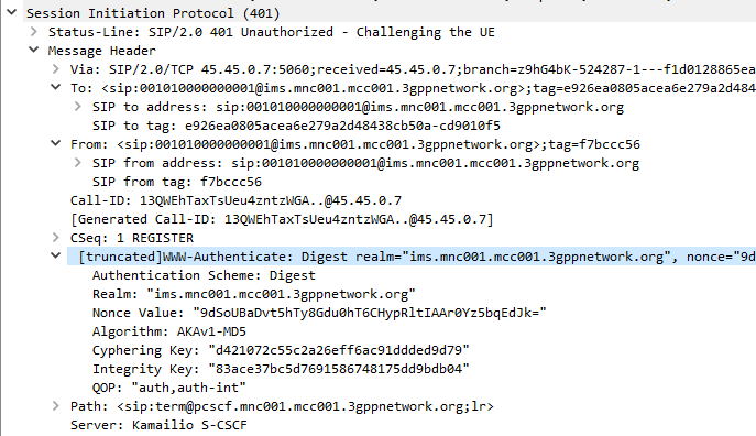
The SIP server sends the Subscriber / UA a SIP 401 Unauthorized response to the initial request, containing a WWW-Authenticate header containing the challenges.
SIP 401 Response with WWW-Authenticate header populated with values from Multimedia-Auth-Answer
The Subscriber / UA sends back the initial request with the WWW-Authenticate header populated to include a response to the challenges. If the response to the challenge matches the correct (“expected”) response, then the user is authenticated.
Multimedia-Authentication-Request
Multimedia-Authentication-Answer
I always find it much easier to understand what’s going on through a packet capture, so here’s a packet capture showing the two Diameter commands,
Note: There is a variant of this process allows for stateless proxies to handle this by not storing the expected authentication values sent by the Diameter server on the SIP Proxy, but instead sending the received authentication values sent by the Subscriber/UA to the Diameter server to compare against the expected / correct values.
The Cryptography
The Cryptography for IMS Authentication relies on AKAv1-MD5 which I’ve written about before,
Essentially it’s mutual network authentication, meaning the network authenticates the subscriber, but the subscriber also authenticates the network.
You may want to connect Open5GS’ MME to a different Home Subscriber Server (HSS),
To do it we need a few bits of information:
The Domain Name of the HSS
The Realm of the HSS
The IP of the HSS
The Transport Used (TCP/SCTP)
If TLS is used
With these bits of information we can go about modifying the Open5GS MME config to talk to our different HSS.
Edit FreeDiameter Config
The config for the Open5GS MME’s Diameter peers is handled by the FreeDimaeter library,
You can find it’s config files in:
/etc/freediameter/mme.conf
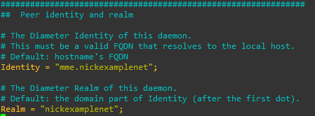
We’ll start by changing the realm to match the realm of the HSS and the identity to match the identity configured as the MME peer on the HSS.
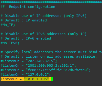
We’ll next set the ListenOn address to be a reachable IP address isntead of just a loopback address,
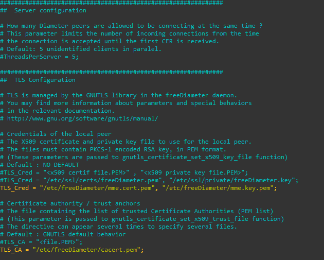
If you’re using TLS you’ll need to put your certificates and private key files into the TLS config,
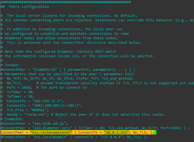
Finally we’ll put our HSS details in the Peer Configuration;
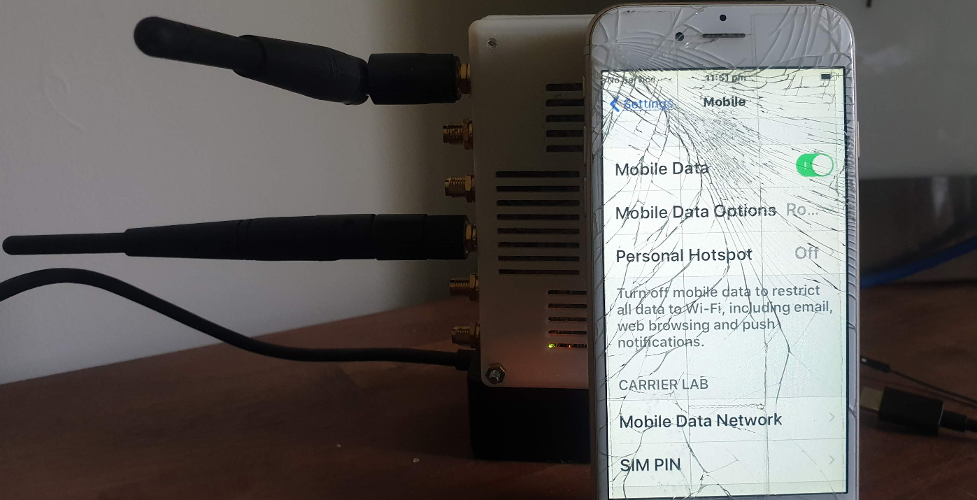
Once all this is done we’ll need to restart our MME and you should see the Diameter Capabilities Exchange / Answer commands between the HSS and the MME if all was successful,
And that’s it! We’re connected to an external HSS.
Through the freeDiameter config file you can specify multiple ConnectPeer() entries to connect to multiple HSS (like a pool of them), and requests will be distributed evenly between them.
Note: I’m running version 19.12.0 which I installed from the repos due to issues with 20.4.0 (latest when I wrote this) and stability on LimeSDR.
I wrote the other day about installing SRS LTE stack,
But installing it is one thing, meeting all the requirements to use it with your SDR hardware turns out to be another whole thing all together.
srsENB is a software defined eNodeB, allowing you to use a Software Defined Radio to serve as an eNodeB, UE and a few other utilities.
SRS’ implementation of the eNB is supposed to be 3GPP R10 compliant and supports eMBMS to boot.
Meeting Dependencies
Installing prerequisites
I’m using a LimeSDR, but these instructions also for for the BladeRF. I found the frequency stability of my BladeRF X40 wasn’t great, meaning when running SRS’s eNodeB the cell wasn’t visible to my UE.
sudo apt install tree vim git g++ make cmake pkg-config python-numpy swig libi2c-dev libusb-1.0-0-dev libfftw3-dev libmbedtls-dev libboost-program-options-dev libconfig++-dev libsctp-dev gnuradio
Install SoapySDR from Source
git clone https://github.com/pothosware/SoapySDR.git
pushd SoapySDR
git checkout tags/soapy-sdr-0.7.2 -b soapy-sdr-0.7.2
mkdir build
cd build
cmake ..
make
sudo make install
sudo ldconfig
popd
Install LimeSuite
You can skip this if you’re using a BladeRF
git clone https://github.com/myriadrf/LimeSuite.git
pushd LimeSuite
#git checkout tags/v19.04.0 -b v19.04.0
mkdir builddir
cd builddir
cmake ..
make
sudo make install
sudo ldconfig
cd ../udev-rules
sudo sh ./install.sh
popd
Install BladeRF
You can skip this if using a LimeSDR
git clone https://github.com/Nuand/bladeRF.git
pushd bladeRF/host/
mkdir build
cd build/
cmake -DCMAKE_BUILD_TYPE=Release -DCMAKE_INSTALL_PREFIX=/usr/local -DINSTALL_UDEV_RULES=ON -DBLADERF_GROUP=plugdev ..
make
sudo make install
sudo ldconfig
sudo mkdir -p /etc/Nuand/bladeRF/
sudo wget https://www.nuand.com/fpga/hostedx40-latest.rbf --output-document /etc/Nuand/bladeRF/hostedx40.rbf
popd


git clone https://github.com/pothosware/SoapyBladeRF.git
pushd SoapyBladeRF
mkdir build
cd build
cmake ..
make
sudo make install
popd
Install SRS GUI
(Optional but makes life easier and has to be done prior to installing SRSLTE)
sudo apt-get install libboost-system-dev libboost-test-dev libboost-thread-dev libqwt-qt5-dev qtbase5-dev
git clone https://github.com/srsLTE/srsGUI.git
pushd srsGUI
mkdir build
cd build
cmake ..
make
sudo make install
popd
Install SRSLTE (SRSenb & SRSue)
pushd srsLTEmkdir build cd build cmake ../ make make test sudo make install sudo ldconfig sudo ./srslte_install_configs.sh service popd
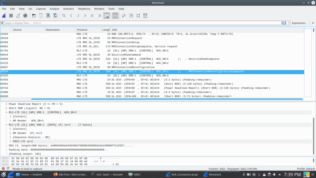
One nifty feature of this interface is that you can send SMS using the MSC to switch the SMS traffic and the LTE/EUTRAN to transfer the messaging.
This means you don’t need Circuit Switched Fallback to send or receive SMS on LTE.
I assume this functionality was added to avoid the signalling load of constantly changing RAN technologies each time a subscriber sent or received an SMS, but I couldn’t find much about it’s history.
In order to get this to work you’ll essentially need the exact same setup I outlined in my CSFB example (Osmo-MSC, Osmo-STP, Osmo-HLR populated with the IMSI and MSISDN values you want to use for SMS), although you won’t actually need a GERAN / GSM radio network.
Once that’s in place you can just send SMS between subscribers,
Plus from the VTY terminal of OsmoMSC you can send SMS too:
I’ve talked about how LTE’s EUTRAN / EPC has no knowledge about voice calls or SMS and instead relies on IMS/VoLTE for these services.
Circuit Switched Fallback allows UEs to use a 2G or 3G network (Circuit Switched network) if their device isn’t connected to the IMS network to make calls as the 2G/3G network can handle the voice call or SMS routing via the Mobile Switching Center in the 2G/3G network.
However for incoming calls destined to the UE (Mobile Terminated) the MSC needs a way to keep track of which MME is serving the UE so it can get a message to the MME and the MME can relay it to the UE, to tell it to drop to a 2G or 3G network (Circuit Switched network).
The signalling between the MME (In the LTE EPC) and the MSC (In the GSM/UTRAN core) is done over the SGs interface.
While the SGs interface is primarily for managing user location state across multiple RAN types, it’s got a useful function for sending SMS over SGi, allowing users on an LTE RAN to send SMS via the MSC of the 2G/3G network (GSM/UTRAN core).
How it Works:
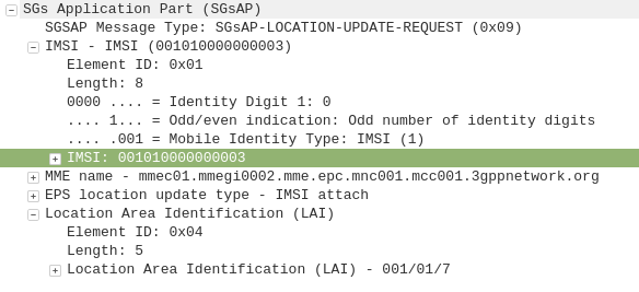
When a UE connects to the LTE RAN (EUTRAN) the MME signals the GSM/UMTS MSC with an SGsAP-LOCATION-UPDATE-REQUEST,
This request includes the IMSI of the subscriber that just attached and the FQDN of the MME serving that UE.
The MSC now knows that IMSI 001010000000003 is currently on LTE RAN served by MME mmec01.mmegi0002.mme.epc.mnc001.mcc001.3gppnetwork.org,
If a call or SMS comes into the MSC destined for the MSISDN of that IMSI, the MSC can page the UE on the LTE RAN to tell it to do an inter-RAN handover to GSM/UMTS.
Setting it Up
In order to get this working you’ll need OsmoMSC in place, your subscribers to exist on OsmoHLR and the LTE HSS – For example Open5GS-HSS.
Once you’ve done that the additional config on OsmoMSC is fairly simple, we just define a new SGs interface to listen on:
OsmoMSC Config:
sgs
  local-port 29118
  local-ip 0.0.0.0
  vlr-name vlr.msc001.mnc001.mcc001.3gppnetwork.org
end
On the Open5GS side we’ve got to include the SGs info the MME config. Keep in mind the Tracking Area Code (TAC) in LTE must exist as the Location Area code (LAC) in GSM, here’s an extract of the MME section of YAML config in the Open5GS MME config:
The EUTRAN will need to advertise the presence of it’s GERAN neighbours and vise-versa so the UE/terminals know what ARFCN to move to so they don’t need to scan for the presence of other RATs when performing the handover.
Setting this up will depend on your eNB / BSC and goes beyond the scope of this post.
I’ll cover setting up neighbours in a later post as it’s a big topic.
If you don’t have neighbours configured, the handover will still work but will be much slower as the UE will have to scan to find the serving cell it’s reselecting to.
I had a few headaches getting the example P-CSCF example configs from the Kamailio team to run, recent improvements with the IPsec support and code evolution meant that the example config just didn’t run.
So, after finally working out the changes I needed to make to get Kamailio to function as a P-CSCF, I took the plunge and made my first pull request on the Kamailio project.
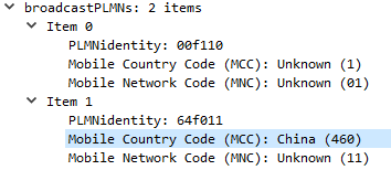
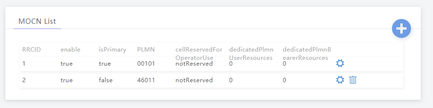
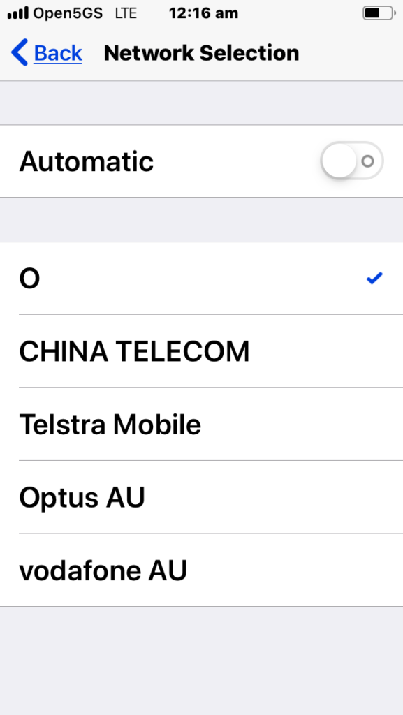
MOCN is one of those great concepts I’d not really come across,
Multi-tenancy on the RAN side of the network, allowing an eNB to broadcast multiple PLMN IDs (MCC/MNC) in the System Information Block (SIB).
It allows site sharing not just on the tower itself, but site sharing on the RAN side, allowing customers of MNO A to see themselves connected to MNO A, and customers from MNO B see themselves as connected to MNO B, but they’re both connected to the same RAN hardware.
Setup in my lab was a breeze; your RAN hardware will probably be different.
In terms of signaling it’s a standard S1AP Setup Request except with multiple broadcast PLMN keys:
This series of post covers RF Planning using Forsk Atoll. We cover the basics of RF Planning in the process of learning how to use the software.
Forsk Atoll is software for RF Planning and Optimization of mobile networks.
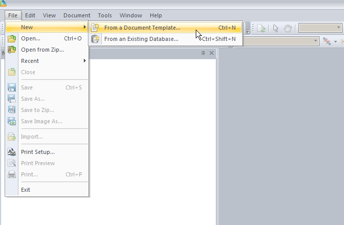
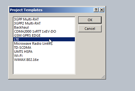
We’ll start by creating a new document from template:
In our example we’re working with LTE, so, we’ll pick the LTE template.
(The templates setup the basic information on what we’re looking at, prediction models and defaults.)
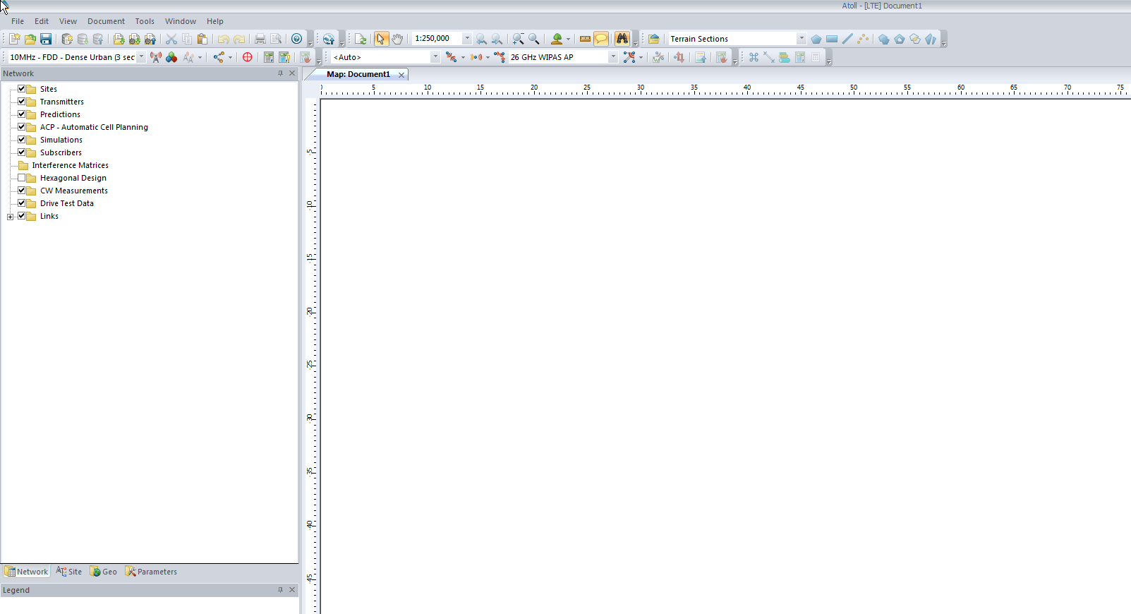
So now we’ll be looking at a blank white document, showing our map, with no data on it, Atoll doesn’t know if the area is hilly, heavily populated, densely treed, what we’re dealing with is a flat void with no features – “flatland” a perfect place to start.
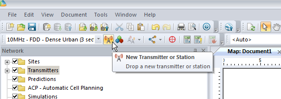
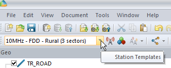
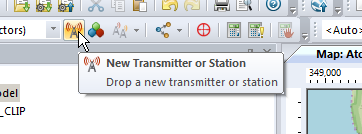
We’ll add an eNodeB (Transmitter Station and Site) from the top menu bar, clicking the transmitter icon to add a new Transmitter or Station.
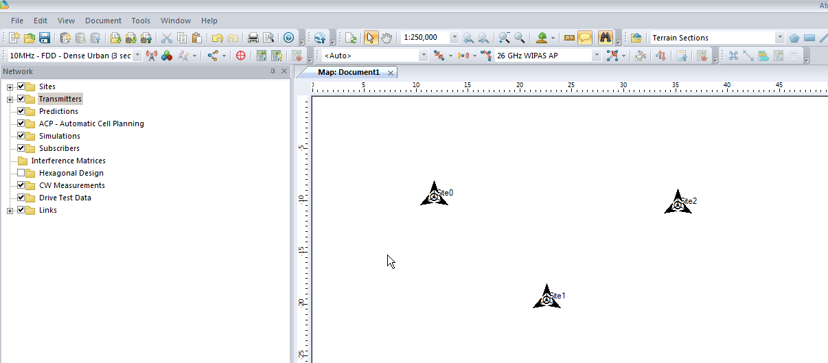
Now we’ll click in the white of our map to place the transmitter site, and repeat this a few times.
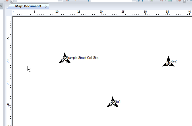
Now we’ve added a few transmitter sites, let’s take a bit of a look at one.
If we take a closer look we’ll see it’s actually created us a 3 sector site, and each of the arrows coming from the site is a cell sector.
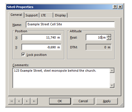
Double clicking on the transmitter will allow us to change the basic info about the site, such as it’s location, as well as display parameters, etc.
In the General tab I’ve renamed Site0 to “Example Street Cell Site”, given it an altitude (for the base of the site) and some comments,
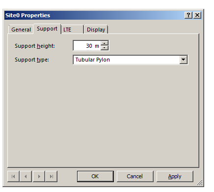
In the Support tab I’ve put some information about the support structure the antennas are one, in our case it’s on a 30m pylon / monopole.
In the LTE tab we can specify S1 throughput (backhaul) and in the Display tab we can set the color / icon used to display this site, but we’ll keep it simple for now and confirm these changes by pressing OK.
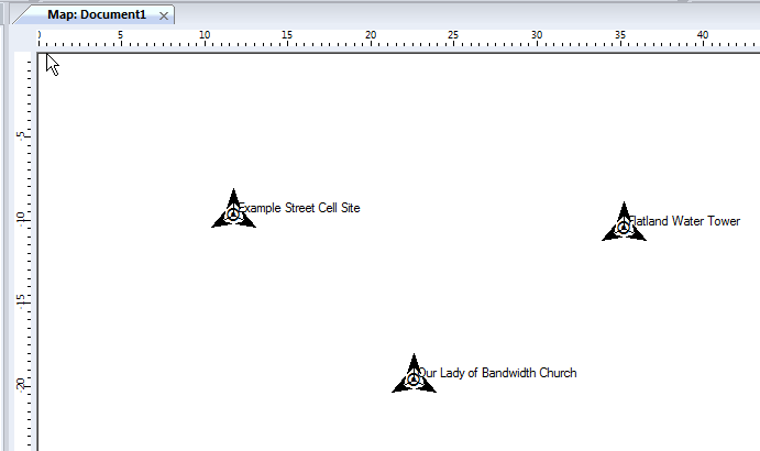
We can give each of our other Transmitters a bit of basic info, again, same process, double click on them and add some info:
So in my example I’ve got 3 transmitter sites, labeled and each given a bit of basic info. The main thing we need to have correct for each site is the location (In our case we’re placing them anywhere so it doesn’t matter), the height of the site (Altitude -Real) and the height of the structure (Support Height) the antennas are on.
Now we’ve got our 3 cell sites in our imaginary town devoid of any features, let’s get some coverage predictions for the inhabitants of desolate featureless town!
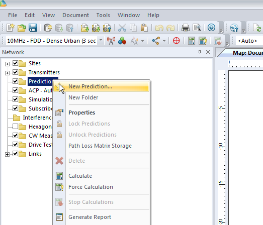
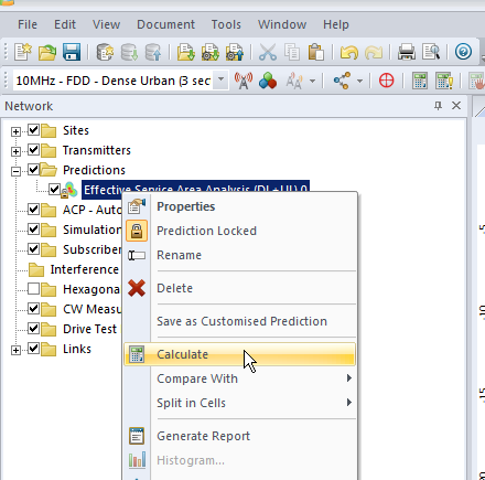
We’ll right click on Predictions and select “New Prediction”,
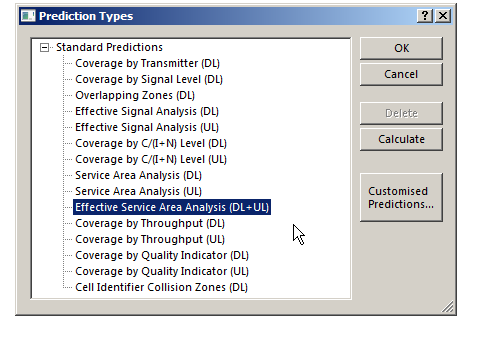
There’s a lot of different prediction types, but let’s look at the Effective Service Area Analysis for Uplink and Downlink from our eNodeBs.
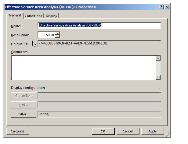
We’ll be asked to give this coverage prediction a name, and also specify a Resolution – The higher the resolution the more processing time but the higher the accuracy calculated.
At 50m it means Atoll will split the map into 50m squares and calculate the coverage in each square. This would be suitable for planning in really rural areas where you want a rough idea of footprint, but for In Building Coverage you’d want far more resolution, so you might want select 5m resolution say.
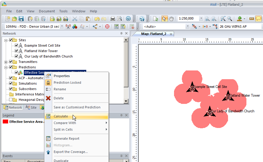
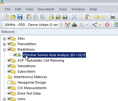
We’ll click Ok and now if we expand “Predictions” we’ll see our catchily named “Effective Service Area Analysis” there.
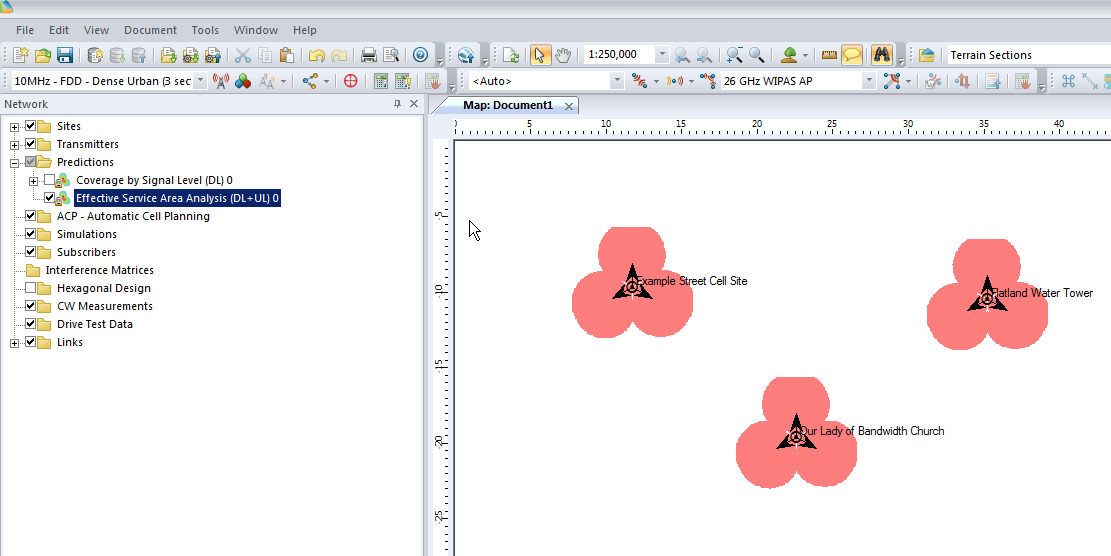
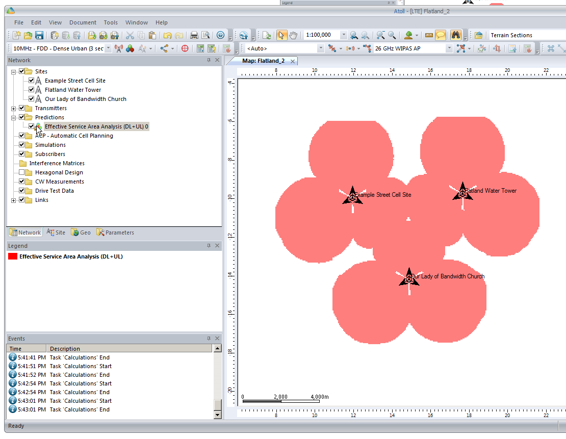
By right clicking on our prediction we can select “Calculate” and presto, we’ll have a prediction of service area from each of our cells,
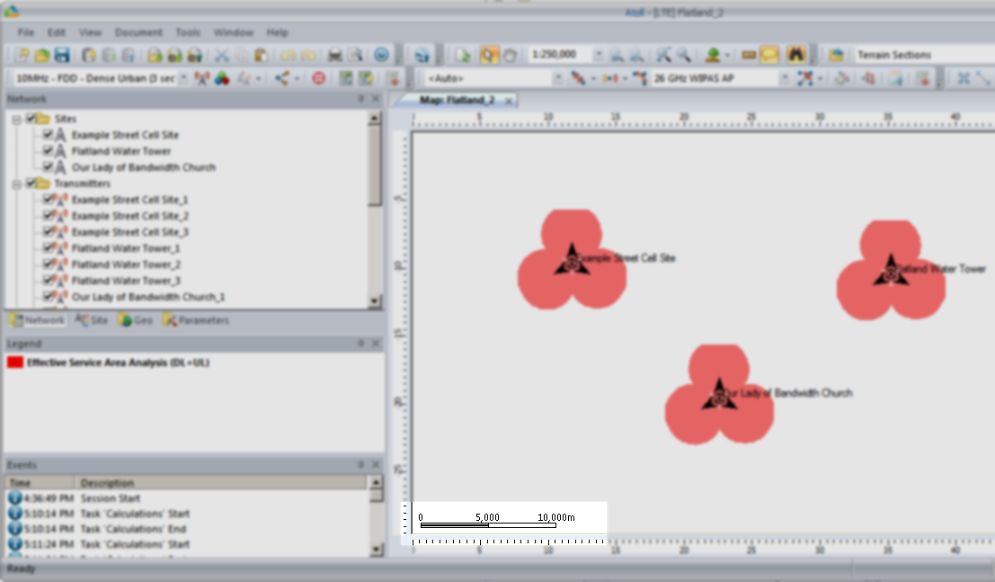
Each of those pink cherry blobs represents the effective usable area of coverage provided by our network.
We may have some unhappy customers looking at this, our users will only be able to use their devices around Fake Street, Flatland Water Tower and the Our Lady of Bandwidth church.
But if we have a look at the scale in the bottom left of the screen that’s understandable, our sites are ~10km apart…
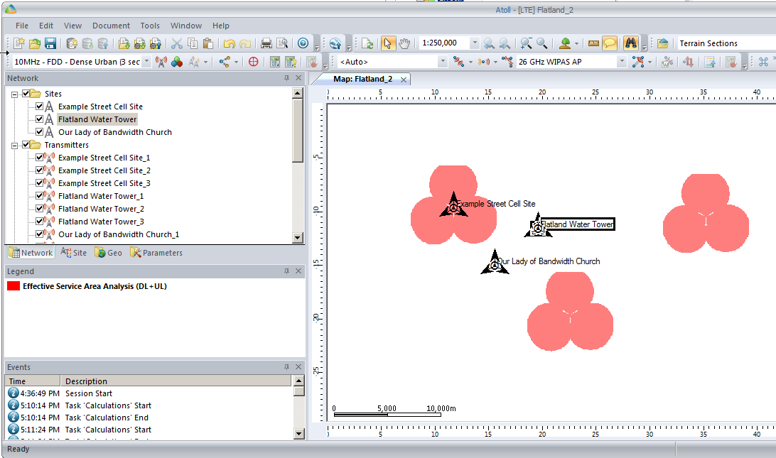
So let’s cheat a little by clicking and dragging on each cell site to bring them closer together, in real life we can’t move sites quite so easily…
You’ll notice our prediction hasn’t changed, so let’s recalculate that by right clicking on our Prediction and selecting Calculate again,
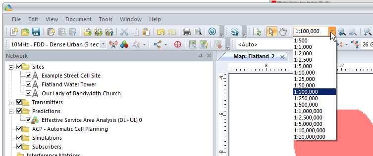
We’ll also set our zoom level from 1:250,000 to something a bit more reasonable like 1:100,000
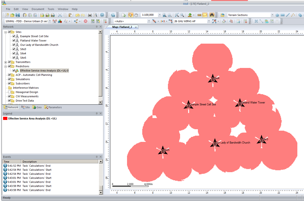
So now our 3 sites have got one area fairly well covered, let’s throw in a few more sites to expand our footprint a bit.
We’ll add extra sites as we did at the start, and fill in those coverage gaps.
After we’ve added some extra sites we’ll recalculate our Coverage Predictions and have a look at how we’ve done.
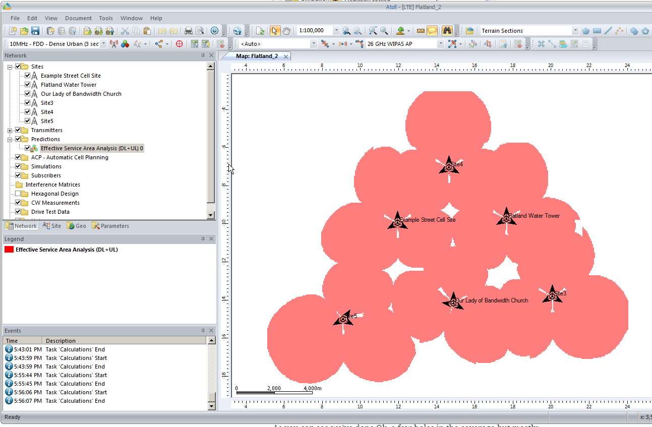
As you can see we’ve done Ok, a few holes in the coverage but mostly covered.
So next let’s do some tweaking to try and increase our predicted coverage,
By clicking on a site’s sector we can reorient the antenna to a different angle, by recalculating the coverage prediction we can see how this effects the predicted coverage.
By now you’ve probably got an idea of the basics of what we’re doing in Atoll, how changing the location, orientation and height of cells / sites affects the coverage, and how you can predict coverage.
In the upcoming posts we’ll cover adding real world data to Atoll so we can accurately model and predict how our RAN will perform.
We’ll look at how we can use Automatic Cell Planning to get the most optimal setup in terms of power settings, antenna orientations and tilts, etc for our existing sites.
We’ll be able to simulate subscribers, traffic flow, backhaul, and model our network all before a single truck rolls.
So stick around, the next post will be coming soon and will cover adding environment data.
In our last post we talked about getting our geospatial data right, and in our first post we covered the basics of adding sites and transmitters.
There’s a bit of a chicken-and-egg problem with site placement, antenna orientation, type and down-tilt.
If all our sites were populated and in place, we could look at optimizing coverage by changing azimuths / orientations, plug in our data and run some predictions / modeling and coming up with some solutions. Likewise if we’ve already done that we might want to calculate ideal down-tilt angles to get the most out of network.
But we’ve got no sites, no transmitters and no coverage predictions yet, so we’re probably going to need to ask ourselves a more basic, but harder question: Where will we put the cell sites?
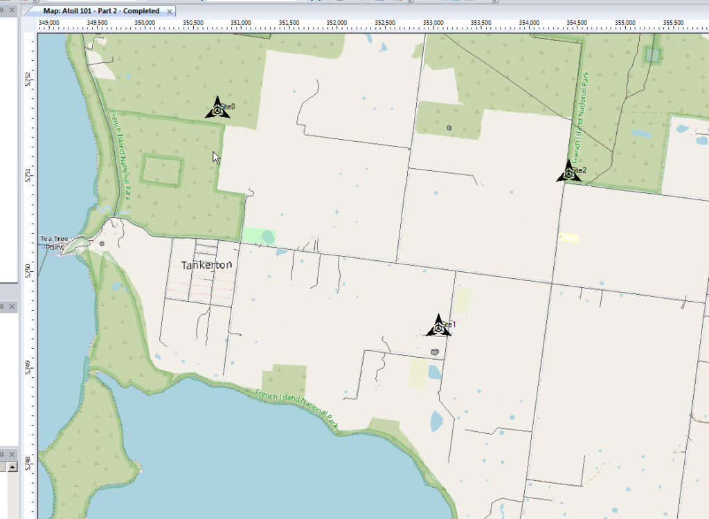
To keep this easy we’ll focus on providing the South Western corner of the Island, a town called Tankerton, with only 3 cell sites.
Manual Site Selection
In the very first post we put up a few sites, we’ll do the same, let’s place 3 sites in the bottom right of the island and attempt to provide contiguous coverage for the town with them;
We’ll pick our Station Template and set it to FDD Rural as this is pretty remote.
Next we’ll add some sites and transmitters:
Click to place it on the map and add our cell sites;
When we’re looking at where to place it, it’s good to remember that height (elevation) is good (To an extent), so when looking at where to place sites, keep an eye on the Z (Height) value in the bottom right, and try and pick sites with a good elevation.
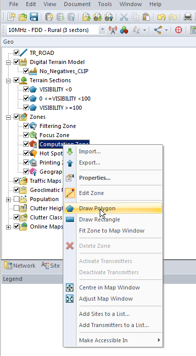
Setting Computation Zone
As we’re only focusing on a small part of the island we’ll set a Computation Zone to limit the calculations / computations Atoll has to do to a set region.
I’ve chosen to draw a Polygon around the area, but you could also just get away with drawing a Rectangle, around the area we’re interested in.
This just constrains everything so we’re only crunching numbers inside that area.
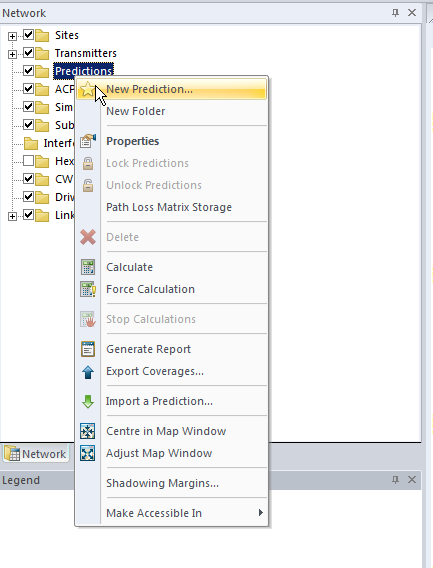
Predictions
So now we’ve put our 3 sites out & constrained to the Tankerton area, let’s see how much of the area we’ve covered, we’ll jump to the Network tab, right click on Predictions and select New Prediction
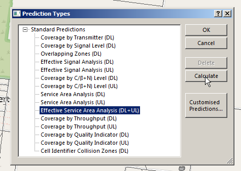
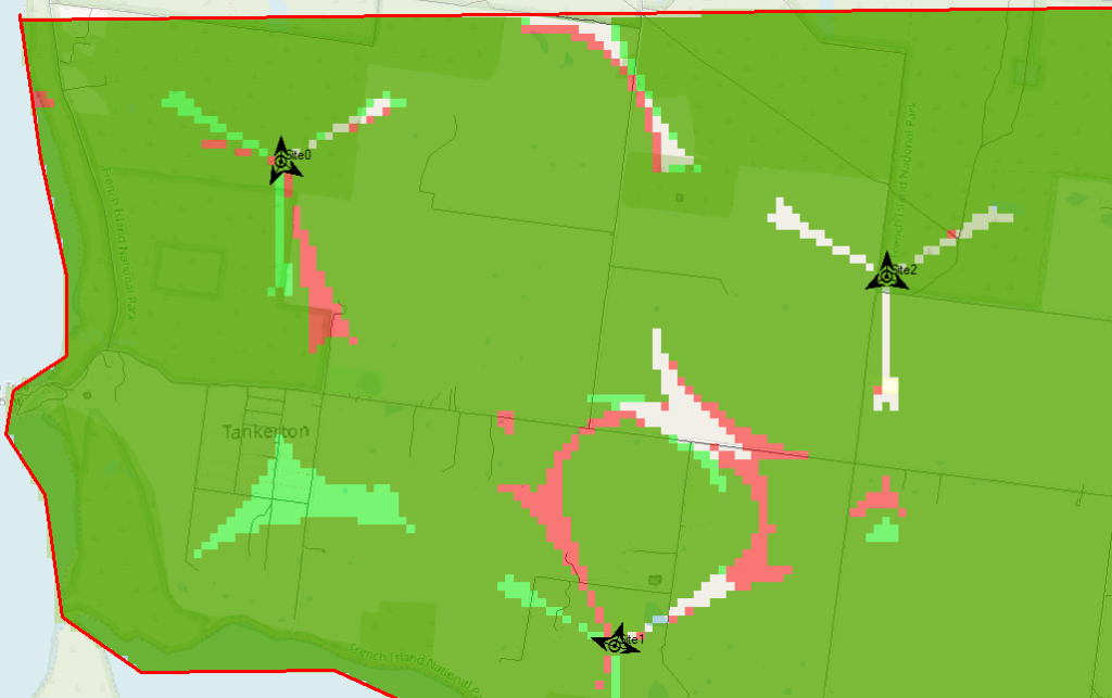
There’s a lot of predictions we can run, but we’ll go simple and select Effective Service Area Analysis (UL + DL) & click Calculate
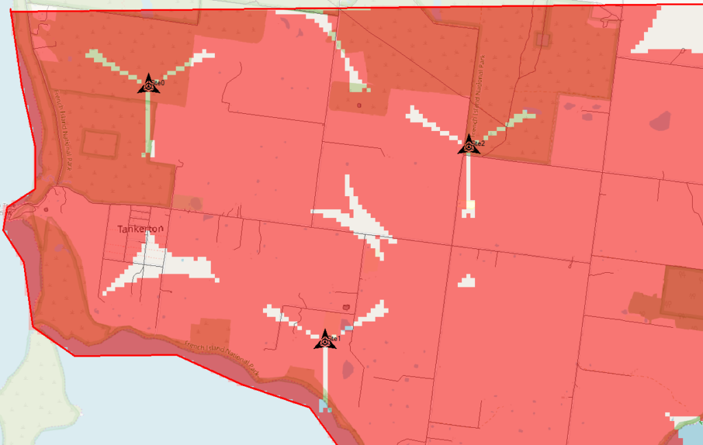
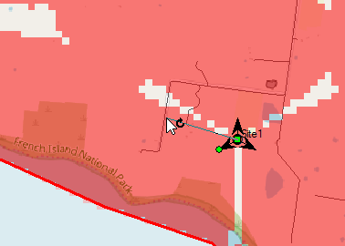
Atoll will crunch the numbers and give us a simple overlay, showing the areas with and without coverage.
The areas in red are predicted to have coverage, and the areas with no shading will be our blackspots / “notspots”.
We’ve covered most of the area, but we can improve.
Manually Tweaking Attributes
So there’s still some holes in our coverage, so let’s adjust the azimuth of some of the antennas and see if we can fill them.
Click on each of the arrows on the site, each of these represents an antenna / cell and we can change the angles.
So after a bit of fiddling I think I’ve got a better antenna azimuth for each of the sectors on each of my 3 sites.
Let’s compare that to what we had before to see if we’ve made it better or worse,
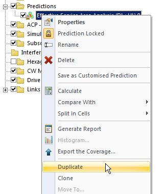
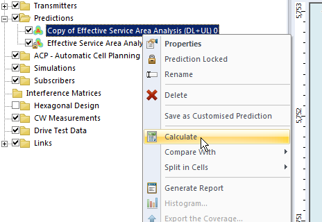
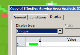
We’ll Duplicate the Effective Service Area Analysis prediction we created before & calculate it.
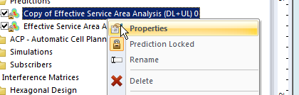
To make viewing a bit easier we’ll edit the properties of the copy and set it to a different colour:
Now I can see at a glance how much better we’re looking;
The obvious problem here is I could tweak and tweak and improve some things, make others worse, and we’d be here forever.
Luckily Atoll can do a better job of fiddling with each parameter for us and selecting the configuration that leads to the best performance in our RAN.
Automatic Cell Planning
Enter Automatic Cell Planning, to adjust the parameters we set to find the most optimal setup,
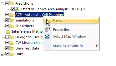
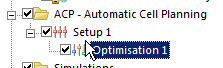
We’ll right click on ACP – Automatic Cell Planning and create a new one.
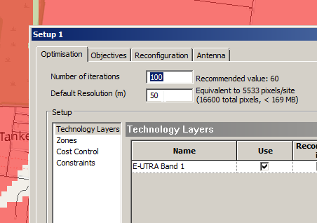
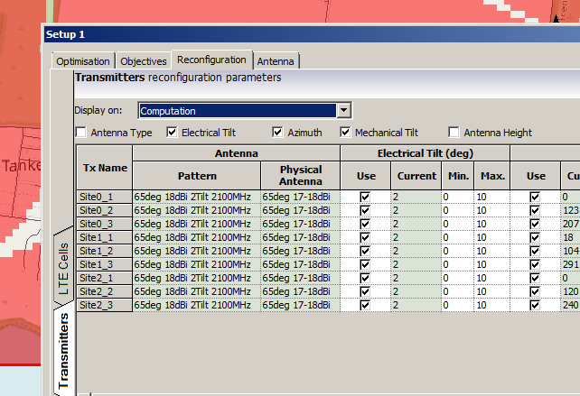
From here we set how many iterations we want to try out (more leads to better results but takes longer to compute), the parameters we want to change (ie Azimuth, Tilt, Antenna type, etc).
Setting number of iterations – Higher leads to better results but takes longer to calculate and has diminishing returnsWe’ll allow the Tilt (Electrical & Mechanical) to be adjusted as well as the Azimuth of each antenna.
When you’ve set the parameters you want, click Run and Atoll will start running through possible parameter combinations and measuring how they perform.
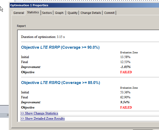
Once it’s run you’ll be able to view the Optomization
The report shows you the results, improvements in RSSI and RSSQ;
Here we can see we boosted the RSRQ (The quality of the signal) by 9.5%, but had to sacrifice RSRP (Signal power) by 1%.
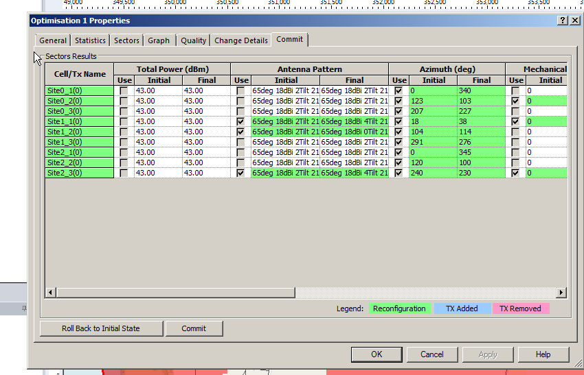
Sacrificies have to be made, and if you’re happy with this you can view the details of the changes, and commit the adjustments.
Committing the changes adjusts all the Transmitters in the area to the listed values, after which we can run our Predictions again to compare like we did earlier.
So that’s what we’ve got when we randomly place sites, we can use Atoll to optomize what we’ve already got, but what if we left the picking of cell sites up to Atoll to look for better options?
In our next post we’ll look at Site Selection using ACP, and constraining it. This means we can tell Atoll to just find the best sites, or load in a list of possible sites and let Atoll determine which are the best candidates.
You’ve done the flatland model we did Part 1 and now you’re pumped up and ready to start plotting your cell sites, optimizing your coverage and boosting the services you’re offering.
But one thing stands in your way – The predicted & modeled data we get out of Atoll is only going to be as good as the data we’ve given it, the old garbage in garbage out adage.
So let’s get started, we’ll create a new document from Template again and select LTE.
Setting our Projection
Now before we go throwing out cell sites we’re going to have to tell Atoll where we are, this can get a little tricky if you’re setting this up for a different real world location, but stick with me and I’ll give you the data you need for this example.
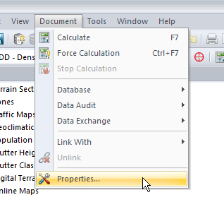
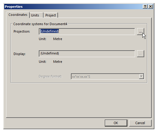
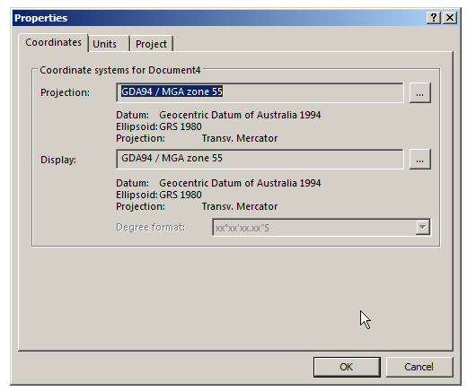
We’ll select Document -> Properties and we’ve got to define a projection,
A projection is essentially a coordinate system, like Latitude and Longitude, that constrains our project to somewhere on this planet.
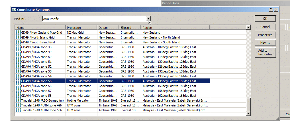
In this example we’re in Australia, so we’ll select Asia Pacific from the “Find In” section and scroll until we find MGA Zone 55. We’ll select it and click OK.
All this Zone information makes sense to GIS folks, there’s lots of information online about UTM datums, projections and GIS, which can help you select the right Coordinate system and projection for your particular area – But for us we’ll select MGA Zone 55 and that’s the last we’ll hear about it.
So now we’ve got that information setup we’ll hit Ok again and be on our way. Atoll now knows where in the world we are and we can start filling in the specifics.
So now we’ve still got an empty map with nothing to show, so let’s add some data.
Adding Population and Roads
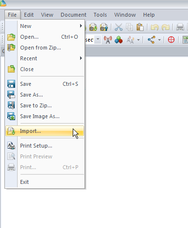
We’ll start by adding some base data, we’ll import a footprint of the Island and a map of all the roads.
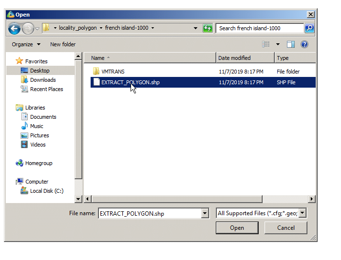
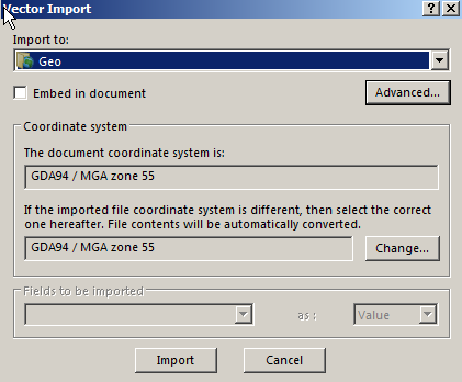
First we’ll import the populated area outline it into Atoll from File -> Import and select the file called EXTRACT_POLYGON.shp
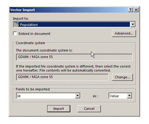
We’ll put it into the population folder, this will be useful later when we try and ensure this area is covered by our network.
Although the population data is kind of rough ( <100 for the entire area) it’s still very useful for limiting our coverage area and saying “We’ve got everyone covered” when it comes to coverage.
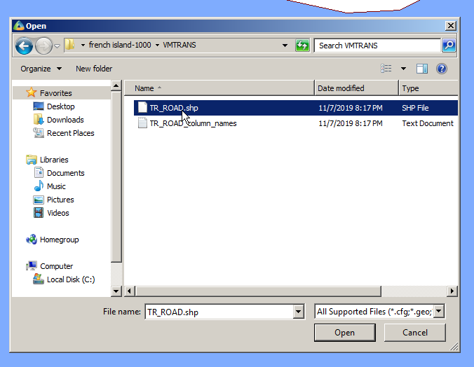
Next up we’ll import the roads file, same thing, File -> Import, TR_ROAD.shp
We’ll import it to the Geo folder – This is just data that Atoll doesn’t process but is useful to us as humans.
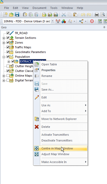
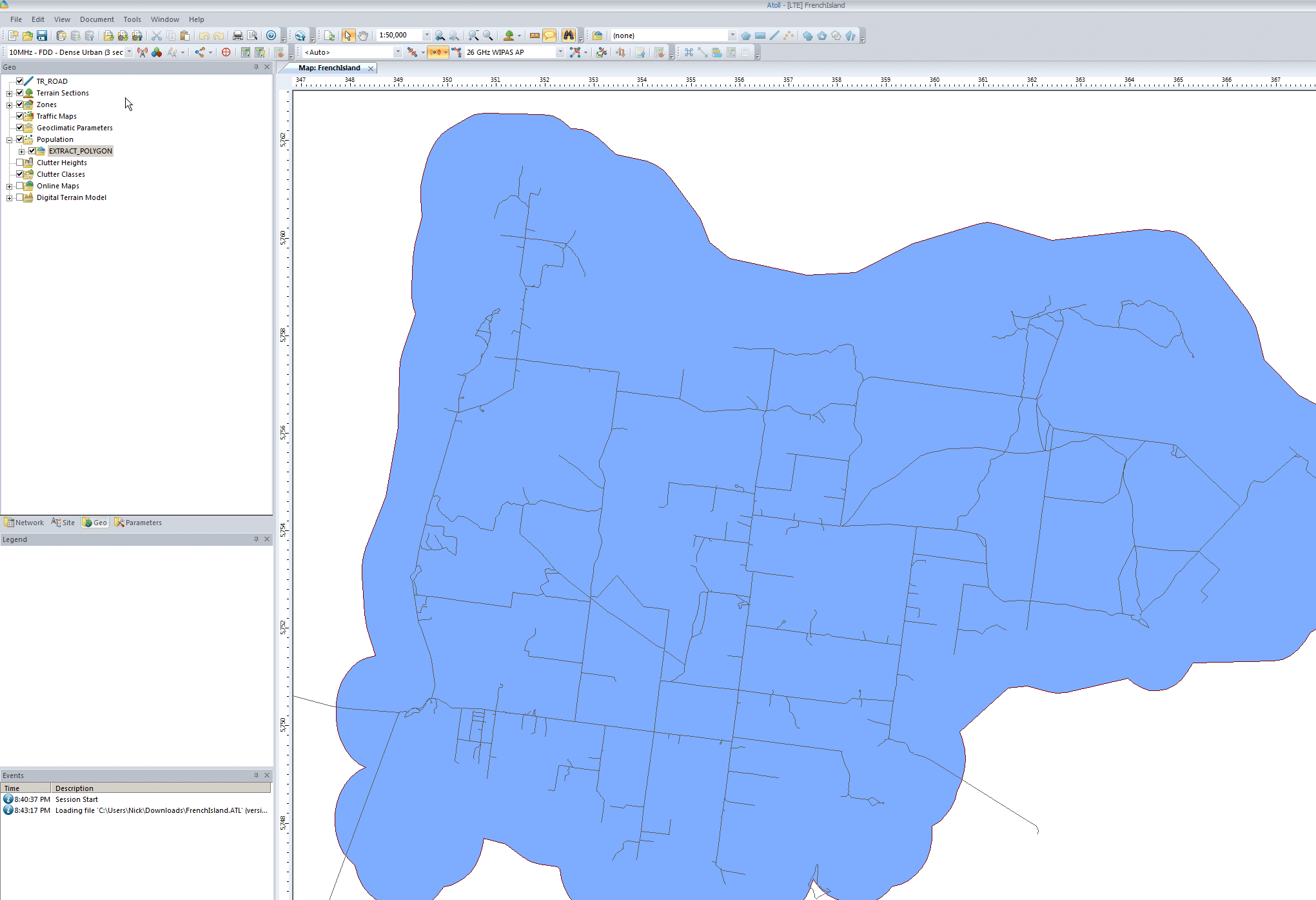
Finally we’ll enable the layers we’ve just imported and center the map on our imported data to get us in the right region. We’ll do this by expanding “Population”, right clicking on the file we just imported and selecting “Center in Map Window”
You may have to tick the layer to enable itPopulation footprint with roads
Adding Elevation Data
Again, like our Datum elevation data is a standard GIS concept, but if you’re from an RF background you’ve probably not come across it, essentially it’s an image where the shade of each pixel translates to a height above sea level.
We import it into Atoll and it’s used in propagation modeling – after all we need to know if there’s a hill / mountain / valley in the way, and even slight rises / dips in the geography can have an impact on your coverage.
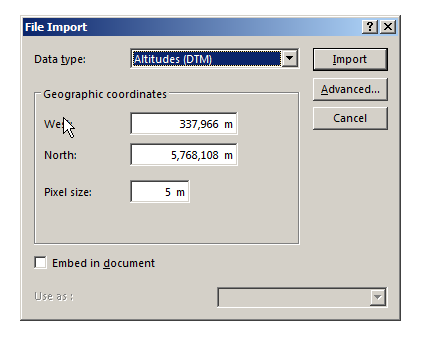
We’ll start by downloading the file above, and then importing it into Atoll
Next we’ll need to tell Atoll the type of data we’re importing (Altitudes) and it’s offset from the 0 point of our coordinate system, I’ve put the information we need for this into a handy table below:
West
337,966
North
5,768,108
Pixel Size
5m
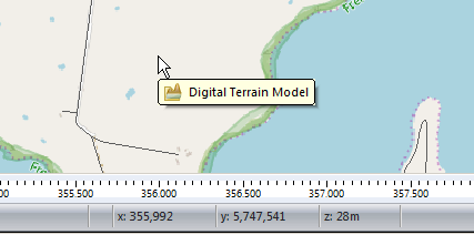
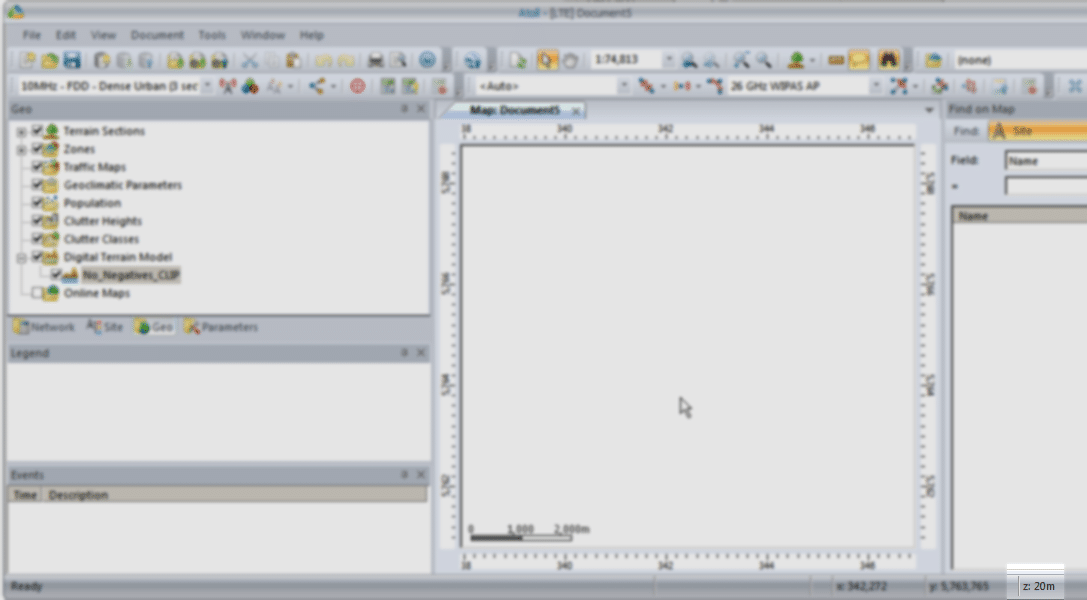
Now when we move our cursor around we’ll see the elevation change in the bottom right ( z is height).
This is because the elevation data is kind of invisible (We’re looking top down) but it’s there.
Adding a Map Overlay
Ok, you’ve made it this far, let’s finally get out of our white blank map and give it some things that make it look like a map!
In order to add Google Maps / Bing Maps etc as an overlay for the first time, we’ve got to restart Atoll, be sure to save your work first.
Done that? Good, let’s add some map tiles.
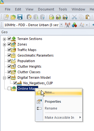
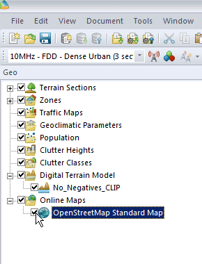
We’ll right click on Online Maps -> New and select a map source from the drop down menu,
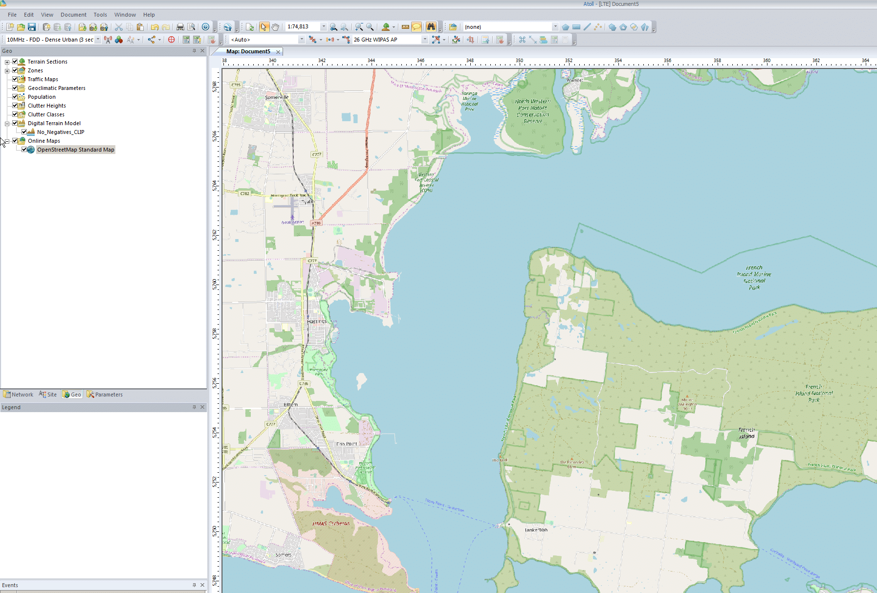
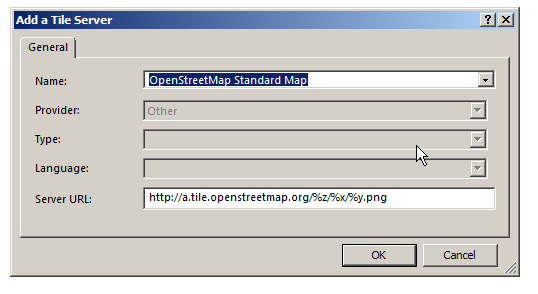
Next we’ll select a tile server, I’m using Open Street Map Standard Map, which I selected from the drop down menu,
Finally we’ll enable the layer by ticking it on the Geo panel on the right hand side. You may need to drag the layer to the top if you’ve added other layers.
All going well you’ll be looking at a map of the area, and by hovering over an area of land you should see the elevation data too.
We can even add other map layers and toggle between them or set the order by dragging them up and down.
Summary
So now we’ve got Atoll configured for our part of the world, imported height data, population data and roads, and added some map layers so we can see what we’re up to.
An important point to keep in mind is the more accurate the data you feed into Atoll, the more real-world the results you’ll get out of it will be.
Although filling in map layers and adding information seems tedious – and it is – the data-in data-out approach applies here, so the more quality data we put in the better.
If you’re doing this yourself in the real world contact your Government, they often publish large amounts of geospatial data like elevation, population, roads, land boundaries, and it’s often free.
I’ve attached my working file for you to play with in case you had any issues.
There’s always lots of talk of Network Function Virtualization (NFV) in the Telco space, but replacing custom hardware with computing resources is only going to get you so far, if every machine has to be configured manually.
Ansible is a topic I’ve written a little bit about in terms of network automation / orchestration.
I wanted to test limits of Open5gs EPC, which led me to creating a lot of Packet Gateways, so I thought I’d share a little Ansible Playbook I wrote for deploying P-GWs.
It dynamically sets the binding address and DHCP servers, and points to each PCRF in the defined pool.
You can obviously build upon this too, creating another playbook to deploy PCRFs, MMEs and S-GWs will allow you to reference the hosts in each group to populate the references.
logger:
    file: /var/log/open5gs/pgw.log

parameter:

pgw:
    freeDiameter: /etc/freeDiameter/pgw.conf
    gtpc:
      - addr: {{hostvars[inventory_hostname]['ansible_default_ipv4']['address']}}

    gtpu:
      - addr: {{hostvars[inventory_hostname]['ansible_default_ipv4']['address']}}

    ue_pool:
      - addr: 45.45.0.1/16
      - addr: cafe::1/64
    dns:
{% for dns in dns_servers %}
      - {{ dns }}
{% endfor %}
Diameter Config (pgw.conf.j2)
# This is a sample configuration file for freeDiameter daemon.

# Most of the options can be omitted, as they default to reasonable values.
# Only TLS-related options must be configured properly in usual setups.

# It is possible to use "include" keyword to import additional files
# e.g.: include "/etc/freeDiameter.d/*.conf"
# This is exactly equivalent as copy & paste the content of the included file(s)
# where the "include" keyword is found.


##############################################################
##  Peer identity and realm

# The Diameter Identity of this daemon.
# This must be a valid FQDN that resolves to the local host.
# Default: hostname's FQDN
#Identity = "aaa.koganei.freediameter.net";
Identity = "{{ inventory_hostname  }}.{{ diameter_realm }}";

# The Diameter Realm of this daemon.
# Default: the domain part of Identity (after the first dot).
#Realm = "koganei.freediameter.net";
Realm = "{{ diameter_realm }}";
##############################################################
##  Transport protocol configuration

# The port this peer is listening on for incoming connections (TCP and SCTP).
# Default: 3868. Use 0 to disable.
#Port = 3868;

# The port this peer is listening on for incoming TLS-protected connections (TCP and SCTP).
# See TLS_old_method for more information about TLS flavours.
# Note: we use TLS/SCTP instead of DTLS/SCTP at the moment. This will change in future version of freeDiameter.
# Default: 5868. Use 0 to disable.
#SecPort = 5868;

# Use RFC3588 method for TLS protection, where TLS is negociated after CER/CEA exchange is completed
# on the unsecure connection. The alternative is RFC6733 mechanism, where TLS protects also the
# CER/CEA exchange on a dedicated secure port.
# This parameter only affects outgoing connections.
# The setting can be also defined per-peer (see Peers configuration section).
# Default: use RFC6733 method with separate port for TLS.
#TLS_old_method;

# Disable use of TCP protocol (only listen and connect over SCTP)
# Default : TCP enabled
#No_TCP;

# Disable use of SCTP protocol (only listen and connect over TCP)
# Default : SCTP enabled
#No_SCTP;
# This option is ignored if freeDiameter is compiled with DISABLE_SCTP option.

# Prefer TCP instead of SCTP for establishing new connections.
# This setting may be overwritten per peer in peer configuration blocs.
# Default : SCTP is attempted first.
#Prefer_TCP;

# Default number of streams per SCTP associations.
# This setting may be overwritten per peer basis.
# Default : 30 streams
#SCTP_streams = 30;

##############################################################
##  Endpoint configuration

# Disable use of IP addresses (only IPv6)
# Default : IP enabled
#No_IP;

# Disable use of IPv6 addresses (only IP)
# Default : IPv6 enabled
#No_IPv6;

# Specify local addresses the server must bind to
# Default : listen on all addresses available.
#ListenOn = "202.249.37.5";
#ListenOn = "2001:200:903:2::202:1";
#ListenOn = "fe80::21c:5ff:fe98:7d62%eth0";
ListenOn = "{{hostvars[inventory_hostname]['ansible_default_ipv4']['address']}}";


##############################################################
##  Server configuration

# How many Diameter peers are allowed to be connecting at the same time ?
# This parameter limits the number of incoming connections from the time
# the connection is accepted until the first CER is received.
# Default: 5 unidentified clients in paralel.
#ThreadsPerServer = 5;

##############################################################
##  TLS Configuration

# TLS is managed by the GNUTLS library in the freeDiameter daemon.
# You may find more information about parameters and special behaviors
# in the relevant documentation.
# http://www.gnu.org/software/gnutls/manual/

# Credentials of the local peer
# The X509 certificate and private key file to use for the local peer.
# The files must contain PKCS-1 encoded RSA key, in PEM format.
# (These parameters are passed to gnutls_certificate_set_x509_key_file function)
# Default : NO DEFAULT
#TLS_Cred = "<x509 certif file.PEM>" , "<x509 private key file.PEM>";
#TLS_Cred = "/etc/ssl/certs/freeDiameter.pem", "/etc/ssl/private/freeDiameter.key";
TLS_Cred = "/etc/freeDiameter/pgw.cert.pem", "/etc/freeDiameter/pgw.key.pem";

# Certificate authority / trust anchors
# The file containing the list of trusted Certificate Authorities (PEM list)
# (This parameter is passed to gnutls_certificate_set_x509_trust_file function)
# The directive can appear several times to specify several files.
# Default : GNUTLS default behavior
#TLS_CA = "<file.PEM>";
TLS_CA = "/etc/freeDiameter/cacert.pem";

# Certificate Revocation List file
# The information about revoked certificates.
# The file contains a list of trusted CRLs in PEM format. They should have been verified before.
# (This parameter is passed to gnutls_certificate_set_x509_crl_file function)
# Note: openssl CRL format might have interoperability issue with GNUTLS format.
# Default : GNUTLS default behavior
#TLS_CRL = "<file.PEM>";

# GNU TLS Priority string
# This string allows to configure the behavior of GNUTLS key exchanges
# algorithms. See gnutls_priority_init function documentation for information.
# You should also refer to the Diameter required TLS support here:
#   http://tools.ietf.org/html/rfc6733#section-13.1
# Default : "NORMAL"
# Example: TLS_Prio = "NONE:+VERS-TLS1.1:+AES-128-CBC:+RSA:+SHA1:+COMP-NULL";
#TLS_Prio = "NORMAL";

# Diffie-Hellman parameters size
# Set the number of bits for generated DH parameters
# Valid value should be 768, 1024, 2048, 3072 or 4096.
# (This parameter is passed to gnutls_dh_params_generate2 function,
# it usually should match RSA key size)
# Default : 1024
#TLS_DH_Bits = 1024;

# Alternatively, you can specify a file to load the PKCS#3 encoded
# DH parameters directly from. This accelerates the daemon start
# but is slightly less secure. If this file is provided, the
# TLS_DH_Bits parameters has no effect.
# Default : no default.
#TLS_DH_File = "<file.PEM>";


##############################################################
##  Timers configuration

# The Tc timer of this peer.
# It is the delay before a new attempt is made to reconnect a disconnected peer.
# The value is expressed in seconds. The recommended value is 30 seconds.
# Default: 30
#TcTimer = 30;

# The Tw timer of this peer.
# It is the delay before a watchdog message is sent, as described in RFC 3539.
# The value is expressed in seconds. The default value is 30 seconds. Value must
# be greater or equal to 6 seconds. See details in the RFC.
# Default: 30
#TwTimer = 30;

##############################################################
##  Applications configuration

# Disable the relaying of Diameter messages?
# For messages not handled locally, the default behavior is to forward the
# message to another peer if any is available, according to the routing
# algorithms. In addition the "0xffffff" application is advertised in CER/CEA
# exchanges.
# Default: Relaying is enabled.
#NoRelay;

# Number of server threads that can handle incoming messages at the same time.
# Default: 4
#AppServThreads = 4;

# Other applications are configured by loaded extensions.

##############################################################
##  Extensions configuration

#  The freeDiameter framework merely provides support for
# Diameter Base Protocol. The specific application behaviors,
# as well as advanced functions, are provided
# by loadable extensions (plug-ins).
#  These extensions may in addition receive the name of a
# configuration file, the format of which is extension-specific.
#
# Format:
#LoadExtension = "/path/to/extension" [ : "/optional/configuration/file" ] ;
#
# Examples:
#LoadExtension = "extensions/sample.fdx";
#LoadExtension = "extensions/sample.fdx":"conf/sample.conf";

# Extensions are named as follow:
# dict_* for extensions that add content to the dictionary definitions.
# dbg_*  for extensions useful only to retrieve more information on the framework execution.
# acl_*  : Access control list, to control which peers are allowed to connect.
# rt_*   : routing extensions that impact how messages are forwarded to other peers.
# app_*  : applications, these extensions usually register callbacks to handle specific messages.
# test_* : dummy extensions that are useful only in testing environments.


# The dbg_msg_dump.fdx extension allows you to tweak the way freeDiameter displays some
# information about some events. This extension does not actually use a configuration file
# but receives directly a parameter in the string passed to the extension. Here are some examples:
## LoadExtension = "dbg_msg_dumps.fdx" : "0x1111"; # Removes all default hooks, very quiet even in case of errors.
## LoadExtension = "dbg_msg_dumps.fdx" : "0x2222"; # Display all events with few details.
## LoadExtension = "dbg_msg_dumps.fdx" : "0x0080"; # Dump complete information about sent and received messages.
# The four digits respectively control: connections, routing decisions, sent/received messages, errors.
# The values for each digit are:
#  0 - default - keep the default behavior
#  1 - quiet   - remove any specific log
#  2 - compact - display only a summary of the information
#  4 - full    - display the complete information on a single long line
#  8 - tree    - display the complete information in an easier to read format spanning several lines.

LoadExtension = "/usr/lib/x86_64-linux-gnu/freeDiameter/dbg_msg_dumps.fdx" : "0x8888";
LoadExtension = "/usr/lib/x86_64-linux-gnu/freeDiameter/dict_rfc5777.fdx";
LoadExtension = "/usr/lib/x86_64-linux-gnu/freeDiameter/dict_mip6i.fdx";
LoadExtension = "/usr/lib/x86_64-linux-gnu/freeDiameter/dict_nasreq.fdx";
LoadExtension = "/usr/lib/x86_64-linux-gnu/freeDiameter/dict_nas_mipv6.fdx";
LoadExtension = "/usr/lib/x86_64-linux-gnu/freeDiameter/dict_dcca.fdx";
LoadExtension = "/usr/lib/x86_64-linux-gnu/freeDiameter/dict_dcca_3gpp.fdx";


##############################################################
##  Peers configuration

#  The local server listens for incoming connections. By default,
# all unknown connecting peers are rejected. Extensions can override this behavior (e.g., acl_wl).
#
#  In addition to incoming connections, the local peer can
# be configured to establish and maintain connections to some
# Diameter nodes and allow connections from these nodes.
#  This is achieved with the ConnectPeer directive described below.
#
# Note that the configured Diameter Identity MUST match
# the information received inside CEA, or the connection will be aborted.
#
# Format:
#ConnectPeer = "diameterid" [ { parameter1; parameter2; ...} ] ;
# Parameters that can be specified in the peer's parameter list:
#  No_TCP; No_SCTP; No_IP; No_IPv6; Prefer_TCP; TLS_old_method;
#  No_TLS;       # assume transparent security instead of TLS. DTLS is not supported yet (will change in future versions).
#  Port = 5868;  # The port to connect to
#  TcTimer = 30;
#  TwTimer = 30;
#  ConnectTo = "202.249.37.5";
#  ConnectTo = "2001:200:903:2::202:1";
#  TLS_Prio = "NORMAL";
#  Realm = "realm.net"; # Reject the peer if it does not advertise this realm.
# Examples:
#ConnectPeer = "aaa.wide.ad.jp";
#ConnectPeer = "old.diameter.serv" { TcTimer = 60; TLS_old_method; No_SCTP; Port=3868; } ;
{% for pcrf in pcrf_hosts %}
ConnectPeer = "{{ pcrf }}" { ConnectTo = "{{ pcrf }}"; No_TLS; };
{% endfor %}


##############################################################