The MAC layer (Media Access Control) handles error correction, and performs multiplexing of services to the same UE at the same time (multiplexing).
Automatic Repeat Request (ARQ)
When data is sent a CRC (Cyclic Redunancy Check) is added, containing a checksum equivalent of the data contained in the message.
The receiver runs the same CRC calculation on the data, and if the CRC value is not equal to the CRC value it received it knows the data is not correct/complete.
There are 3 scenarios shown below:
Scenario 1 – Data is sent and the CRC calculated by the sender matches the CRC calculated by the reciver. An ACK is sent to confirm the data was received correctly.
Scenario 2 – Data is sent and the CRC calculated by the sender does not match the CRC calculated by the receiver. The receiver sends a NACK (Negative Ack), The sender sends the data again, the CRC this time matches, so an ACK is sent to confirm the data was received correctly.
Scenario 3 – Data is sent by not ACK or NACK was received. This could mean the data was not received, or the ACK/NACK was not received. The sender then sends the message again. This process is repeated a set number of times after which if no response is received the sender gives up.
Acknowledgement
This technique is called Send and Wait ARQ, because the sender must send the data and wait for an ACK/NACK, and will automatically request re-transmission.
Because CRC may take some time to calculate the ACK/NACK is given time to process by the receiver and the ACK/NACK is sent 4ms after it was received.
If a NACK is received the data is re-transmitted 4ms after receipt of the NACK.
This means all up it takes up to 8ms (8 subframes) to send the data, wait for the response and send again if needed. During this time no other data would be sent.
As you can imagine this isn’t a particularly efficient use of time or resources, so the EUTRAN specs define 8 Send and Wait processes in parallel.
While the first process is blocked waiting for an ACK/NACK, another process can transmit. This is called Parallel Send and Wait.
The problem with this is it can lead to data being received out of sequence, as if data is sent and a re-transmission is needed (NACK received by sender) that data will be received after the data sent 8 frames after it.
Here we can see Block 2 was lost, a NACK was sent and a re-transmission occurs 8 subframes later, long after Block 3 and Block 4 were received.
The MAC layer does not deal with re-sequencing, this is managed by the RLC layer above the MAC layer.
Hybrid ARQ
LTE relies on Hybrid ARQ. To increase redundancy and increase the possibility of decoding a corrupted message correctly.
We talked about coding – sending multiple copies of the same data and comparing them to find the common features that would indicate correct data, Hybrid ARQ functions in much the same way.
To increase error correction performance the receiver keeps the invalid/corrupt messages it sends a NACK for, so it can compare it to the re-transmitted version and hopefully correctly decode the message even if the re-transmission is corrupted.
It is called Hybird because the MAC layer has to communicate to the physical layer to let is know this is a re-transmission and not a new transmission.
Multiplexing on the MAC Layer
You may use your smartphone (UE) for a voice call while looking up something online and getting push notifications, while these are 3 distinct streams of data, there is only one stream of data to and from the eNB <-> UE.
These different types of data all need to be combined into one “pipe” between the eNB and UE, this is known as multiplexing.
The RLC layer has multiple types of data arranged in logical channels, but this data has to be put into a MAC PDU and sent over the air.
In the standard networking model, data in an upper layer is called SDU “Service Data Units”, and data in a lower layer is called a PDU “Protocol Data Units”.
To form the transport blocks the MAC layer must take each of the SDUs from the RLC layer, and put it into the transport block, as show in the image above.
The MAC header contains the delineation of what data is for which SDU on the RLC layer.
To inform UEs of which resources are allocated to it, the eNB regularly publishes Allocation Tables with this information.
Resources are allocated dynamically, by the eNB to all the UEs it is serving.
Because the eNB manages all the resources, the eNB must inform the UEs which resources are allocated to which UEs.
This is broken into two functions:
A UE must be able to be informed it’s going to receive data (downlink) and be allocated the resources for it.
A UE must be able to request resources from the eNB to send data (uplink) and be allocated resources for it.
The eNB manages all resource allocation, for downlink and uplink, when they are needed. This is done through an allocation table published by the eNB every subframe (1ms).
There are two allocation tables – One for uplink, one for downlink.
Addressing on the Radio Interface – RNTI
As an allocation table needs to allocate resources to each UE it needs a way to address them.
GUTI, IMSI, TMSI etc, are all too long (allocation tables are published every subframe so need to be a small as possible).
Instead for addressing in the allocation tables as RNTI – Radio Network Temporary Identifier is issued by the eNB to each UE it is serving, the RNTI is issued by the eNB and only valid for that cell, if the user moves to another cell served by another eNB another RNTI is allocated by that eNB.
The RNTI is 16 bits long, meaning it can store 65,536 decimal values. (65,536 UEs)
Allocation on Downlink
Resource allocation for the downlink is managed by the eNB, which publishes allocation tables every subframe defining which resource blocks are allocated to which UE.
The resource blocks contains the RNTI of each UE to receive data and the resource blocks it’s data will be contained in.
Each UE listens for the allocation tables published in each subframe, and if the UE sees it’s own RNTI in the allocation table it listens on the resource blocks allocated to it.
In the example above we can see the allocation table in the dark blue colour, published every 1ms (aka every subframe).
In this example the UE that has been assigned RNTI 63 (represented in green) has got resource blocks 12 & 13 assigned to it, so will listen on 12 and 13 to get it’s downlink data.
Because UEs only listen for the allocation tables and the resource blocks assigned to them, it leads to power savings on the UE as they don’t all need to listen / decode to all resource blocks. Power savings on the UE translate to better battery efficiency.
The UE with RNTI 61 for example, does not get allocated any resource blocks in the downlink in the example allocation table, so it listens for the allocation table and then goes into standby mode until the next allocation table is published.
The allocation tables are contained in the Physical Downlink Control Channel (PDCCH) a channel used only by the eNB to broadcast resource allocation tables and control data.
The actual downlink data for each UE is contained in the Physical Downlink Shared Channel (PDSCH)
Allocation in the Uplink
Allocation in the uplink is similar to allocation in the downlink, however there are some important differences.
The UE must request the resources from the eNB and wait for them to be allocated in the next uplink resource block.
There is a 4ms delay between a resource block being allocated in an allocation table by the eNB for the uplink and it being used by the UE to send data. This gives the UE time to get the data ready to go into the resource block.
The UE requests a resource from the eNB (covered later) and the eNB publishes an allocation table in the next subframe, however this allocation table is to be used in 4 subframes time.
The UE then buffers this allocation table and uses it in 4 subframes time.
By having this delay in using the resource table / allocating resource tables in advance, it allows our UEs to prepare the message for transmission, encode it, modulate it, etc.
The image below shows the UE in red requesting a resource for uplink from the eNB, the eNB then publishes the allocation table for 4 subframes time, the UE waits for 4 subframes to pass and then the UE transmits using the resources allocated in the allocation table published 4ms prior.
For example in the image below the UE with the RTNI of 64, represented in light blue, has requested a resource to send data (uplink), the eNB publishes an uplink allocation table in the next subframe, and the UE has then 4 subframes to prepare the data for transmission before sending the data using the resources allocated in the allocation table sent to it 4 subframes prior.
Like in the Downlink, Uplink transmissions are managed by a Control Channel and data is contained within a Data Channel.
The Physical Uplink Control Channel(PUCCH) contains the control information and the resource tables for the uplink (to be used in 4 subsframes time), shown in gray.
The data being sent from the UEs is contained in Physical Uplink Shared Channels (PUSCH) allocated 4ms prior in a PUCCH.
When a UE has data to transmit it transmits on the PUCCH to request a resource block for the uplink data.
As spectrum is sparse and expensive, so it must be used wisely and shared across multiple users.
LTE shares spectrum in both frequency and time.
LTE can use bandwidths from 1.4Mhz to 20Mhz, based on the spectrum owned and needs of the area.
Spectrum is divided into sub-carriers, allowing each subcarrier to be allocated to a different user, and these subcarriers are re-allocated by the eNB based on the terminal’s needs.
Resource Element (RE)
A Resource Element is the time and frequency a single symbol can be transmitted on.
Resource Elements are allocated by the eNB to UEs and the UE transmits on it’s allocated resource element one symbol.
The size of the data in the symbol is defined by the MCS used.
One Resource Element is contained within 1 subcarrier of 15kHz lasting 66μ s.
Resource Blocks (RB)
Because resource elements are so small, they’re managed in Resource Blocks.
Each Resource Block lasts 0.5ms with 12 sub carriers on each, allowing for 84 Resource Elements in per Resource Block.
The number of Resource Blocks that can be used is determined by the spectrum available.
As we can calculate a Resource Block occupies 180kHz of bandwidth, how many Resource Blocks we can have is determined by how many will fit into our bandwidth.
A system using the minimum bandwidth of 1.4Mhz will have 6 RBs available (1.4Mhz divides into 6 complete 180kHz RBs), while one using the maximum of 20Mhz will have 100 RBs available.
Not all the REs in an RB can be used by terminals though, many of them are reserved for LTE control channels.
Meaning only the white REs shown above can be filled with user traffic.
Sub-Frame
Every 1ms (or 2 Resource Blocks) LTE reallocates the RBs to the terminals that need to communicate.
This means Resource Blocks are allocated in pairs, called a subframe, lasting 1ms.
Subframe, RB, RE Hierarchy
Each subframe is 1ms long and made up of 2 0.5ms Resource Blocks.
Each Resource Block contains 84 Resource Elements, each of which contain one symbol of data.
Resource Allocation in Uplink
When a device needs to transmit data it is allocated one or more resource blocks.
If the number of resource blocks is not enough it can be allocated more in the next subframes.
The amount of data a device can transmit in each subframe is called a Transport Block and is made up of the number of RBs and the modulation (MCS) used.
The sub frame containing contain data for various terminals is shown below in different colors.
Transmission Chain
Transport Blocks are filled with data based on the Transport Block size.
CRC is added to detect errors.
Data is encoded to help recover data containing errors. (Defined by MCS)
Data is modulated (Using modulation scheme defined by MCS)
Data is transmitted in the user-data part that has been allocated in one or more Resource Block Pairs.
The E-UTRAN relies on Phase Shift Keying to modulate data.
The downlink uses orthogonal frequency division multiplex (OFDM) while the uplink uses SC-FDMA due to OFDM’s high peak-to-average-power ratio making it unstable for uplink due to power consumption requirements.
Binary Phase Shift Keying (BPSK)
The simplest modulation is Binary Phase Shift Keying, allowing the phase to be left unmodified to encode a 0, or offset by 180 degrees (aka π) to transmit a 1.
While each bit of data is being transmitted, the time it is being sent over the air is referred to as the symbol length.
Quaternary Phase Shift Keying (QPSK)
QPSK adds to additional phase states, to allow us to send twice as much data in one symbol.
This is done by defining more than two states (phase unmodified, phase offset by pi), but rather 4 states:
Data
Phase Offset
00
π/2
11
5π/2
01
3π/2
10
7π/2
This means we can transmit double the number of bits in a single symbol, with QPSK we can now transmit 2 bits per symbol as per the table above.
This means the data rate of QPSK is twice that of BPSK.
BPSK vs QPSK
Thanks to interference, drift, Doppler shift etc, our modulated data probably isn’t going to be received at exactly the same offset that it was sent.
So because our phase shift isn’t going to land exactly on the red dot in the circle, but somewhere nearby.
The receiver will determine the phase of the signal based on it’s proximity to a known phase shift angle.
Because QPSK has more phase states than BPSK we get a higher data rate, but as the recieved data isn’t going to be exactly the phase offsets defined, the states may overlap and the receiver will not receive the correct information
Channel conditions restrict the modulation techniques we can use. BPSK is slower but more reliable, while QPSK is faster but more error prone due to it’s lower tolerances.
Transmission Reliability
Error Correction is needed in LTE to make sure the message can be reconstructed correctly by the reciever.
To do this, in a simple form LTE adds redundant data.
For example sending 3 copies of the data increases the chance one will get through correctly, and provides the receiver with information to discriminate the right data.
(If only two copies were sent to increase the reliability, the receiver wouldn’t know which one was the correct one.)
Let’s take an example of sending the message “Hello World” and look at the 3 copies sent.
Copy 1: Helso Wdrld
Copy 2: H1llo Worlp
Copy 3: qello Uorld
Correct Data: Hello World
By looking at what’s common we can see that the first letter is H in the first to copies, but not in the third copy, so we can say with some surety that the first letter is H.
The second letter is e in copy 1 and copy 3, so we can again say the second letter is e.
This is a simplified example of coding the data with redundant data to aid in reconstruction.
The ratio of useful information / total transmitted is called the coding rate.
LTE coding rates can vary from 1/3 for extensive error correction, to close to 1 for almost no error correction.
Modulation Coding Scheme (MCS)
As channel conditions change continuously for each terminal/UE, LTE has to change the modulation technique and coding rate dynamically as channel conditions change for each terminal/UE.
The Modulation Coding Scheme is the combination of modulation and coding scheme used, and this changes/adapts in real time based on the signal conditions, independently for each terminal/UE.
HTable is Kamailio’s implimentation of Hash Tables a database-like data structure that runs in memory and is very quick.
It’s uses only become apparent when you’ve become exposed to it.
Let’s take an example of protecting against multiple failed registration attempts.
We could create a SQL database called registration attempts, and each time one failed log the time and attempted username.
Then we could set it so before we respond to traffic we query the database, find out how many rows there are that match the username being attempted and if it’s more than a threshold we set we send back a rate limit response.
The problem is that’s fairly resource intensive, the SQL data is read and written from disks and is slow to do both.
Enter HTable, which achieves the same thing with an in-memory database, that’s lightning fast.
Basic Setup
We’ll need to load htable and create an htable called Table1 to store data in:
$sht(MessageCount=>test) is the logical link to the Htable called MessageCount with a key named test. We’re making that equal itself + 1.
We’re then outputting the content of $sht(MessageCount=>test) to xlog too so we can see it’s value in Syslog.
Now each time a new dialog is started the MessageCount htable key “test” will be incremented.
We can confirm this in Syslog:
ERROR: : MessageCount is 1 ERROR: : MessageCount is 2
We can also check this in kamcmd too:
htable.dump MessageCount
Here we can see in MessageCount there is one key named “test” with a value of 6, and it’s an integer. (You can also store Strings in HTable).
So that’s all well and pointless, but let’s do make it a bit more useful, report on how many SIP transactions we get per IP. Instead of storing our values with the name key “test” we’ll name it based on the Source IP of the message, which lives in Psedovariable $si for Source IP Address.
I’m calling the boilerplate AUTH block, and I’ve added some logic to increment the AuthCount for each failed auth attempt, and reset it to $null if authentication is successful, thus resetting the counter for that IP Address.
Now we’ve done that we need to actually stop the traffic if it’s failed too many times. I’ve added the below check into REQINIT block, which I call at the start of processing:
if($sht(AuthCount=>$si) > 5){
xlog("$si is back again, rate limiting them...");
sl_send_reply("429", "Rate limiting");
exit;
}
Now if AuthCount is more than 5, it’ll respond with a Rate Limiting response.
Because in our modparam() setup for AuthCount we set an expiry, after 360 seconds (10 minutes), after 10 minutes all will be forgiven and our blocked UA can register again.
Advanced Usage / Notes
So now we’ve got Kamailio doing rate limiting, it’s probably worth mentioning the Pike module, which can also be used.
You’ll notice if you reboot Kamailio all the htable values are lost, that’s because the hashes are stored in memory, so aren’t persistent.
You have a few options for making this data persistent,
By using DMQ you can Sync data between Kamailio instances including htable values.
kamcmd can view, modify & manipulate htable values.
As we’ve seen before we can dump the contents of an htable using:
kamcmd htable.dump MessageCount
We can also add new entries & modify existing ones:
kamcmd htable.seti MessageCount ExampleAdd s:999
htable.seti is for setting integer values, we can also use htable.sets to set string values:
htable.sets MessageCount ExampleAdd Iamastring
We can also delete values from here too, which can be super useful for unblocking destinations manually:
htable.delete MessageCount ExampleAdd
As always code from this example is on GitHub. (Please don’t use it in production without modification, Authentication is only called on Register, and it’s just built upon the previous tutorials).
There are a number of ways to feed Homer data, in this case we’re going to use Kamailio, which has a HEP module, so when we feed Kamailio SIP data it’ll use the HEP module to encapsulate it and send it to the database for parsing on the WebUI.
We won’t actually do any SIP routing with Kamailio, we’ll just use it to parse copies of SIP messages sent to it, encapsulate them into HEP and send them to the DB.
We’ll be doing this on the same box that we’re running the HomerUI on, if we weren’t we’d need to adjust the database parameters in Kamailio so it pushes the data to the correct MySQL database.
Next we’ll need to configure captagent to capture data and feed it to Kamailio. There’s two things we’ll need to change from the default, the first is the interface we capture on (By default it’s eth0, but Ubuntu uses eth33 as the first network interface ID) and the second is the HEP destination we send our data to (By default it’s on 9061 but our Kamailio instance is listening on 9060).
We’ll start by editing captagent’s socket_pcap.xml file to change the interface we capture on:
vi /etc/captagent/socket_pcap.xml
Next we’ll edit the port that we send HEP data on
vi /etc/captagent/transport_hep.xml
And finally we’ll restart captagent
/etc/init.d/captagent
Now if we send SIP traffic to this box it’ll be fed into HOMER.
In most use cases you’d use a port mirror so you may need to define the network interface that’s the destination of the port mirror in socket_pcap.xml
HOMER is a popular open source SIP / RTP debug / recording tool.
It’s architecture is pretty straight forward, we have a series of Capture Agents feeding data into a central HOMER Capture Server, which runs a database (today we’re using MySQL), a Homer-UI (Running on Apache), a Homer-API (Also running on Apache) and a HEP processor, which takes the HEP encoded data from the Capture Agents and runs on Kamailio. (That’s right, I’m back rambling about Kamailio)
So this will get the web interface and DB backend of HOMER setup,
For HOMER to actually work you’ll need to feed it data, in the next tutorial we’ll cover configuring a capture agent to feed the HEP processor (Kamailio) which we’ll also setup, but for now we’ll just setup the web user interface for HOMER, API and Database.
Caller-ID spoofing has been an issue in most countries since networks went digital.
SS7 doesn’t provide any caller ID validation facilities, with the assumption that everyone you have peered with you trust the calls from. So because of this it’s up to the originating switch to verify the caller ID selected by the caller is valid and permissible, something that’s not often implemented. Some SIP providers sell the ability to present any number as your CLI as a “feature”.
There’s heaps of news articles on the topic, but I thought it’d be worth talking about RFC4474 – Designed for cryptographically identifying users that originate SIP requests. While almost never used it’s a cool solution to a problem that didn’t take off.
It does this by adding a new header field, called Identity, for conveying a signature used for validating the identity of the caller, and Identity-Info for a reference to the certificate signing authority.
The calling proxy / UA creates a hash of it’s certificate, and inserts that into the SIP message in the Identity header.
The calling proxy / UA also inserts a “Identity-Info” header containing
The called party can then independently get the certificate, create it’s own hash of it, and if they match, then the identity of the caller has been verified.
Sometimes standards are created that are superior in some scenarios, and just don’t get enough love.
To me Stream Control Transmission Protocol (SCTP) is one of those, and it’s really under-utilised in Voice.
Defined by the SIGTRAN working group in 2000 while working to transport SS7 over IP, SCTP takes all the benefits of TCP, mixes in some of the benefits of UDP (No head of line blocking) and mutihoming support, and you’ve got yourself a humdinger of a Transmission Protocol.
Advantages
Reliable Transmission
Like TCP, SCTP includes a reliable transmission mechanism that ensures packets are delivered and retries if they’re not.
Multi Homing
SCTP’s multi homing allows a single connection to be split across multiple paths. This means if you had two paths between Melbourne and Sydney, you could be sending data down both simultaneously.
This means a loss of one transmission path results in the data being sent down another available transmission path.
If you’re doing this using TCP you’d have to wait for the TCP session to expire, BGP to update and then try again. Not so with SCTP.
No Head of Line Blocking
An error / discard with a packet in a TCP stream requires a re-transmission, blocking anything else in that stream from getting through until the error/discarded packet is sorted out. This is referred to as “head of line blocking” and is generally avoided by switching to UDP but that looses the reliability.
4 Way Handshake
Compared to TCP’s 3-way handshake which is susceptible to SYN flooding.
Deployment
If you’ve got a private network, chances are it can support SCTP.
There’s built in SCTP support in almost all Linux kernels since 2002, Cisco iOS and VxWorks all have support, and there’s 3rd party drivers for OSX and Windows.
SCTP is deployed in 3GPP’s LTE / EPC protocol stack for communication over S1-AP and X2 interfaces, meaning if you’ve got a LTE enabled mobile you’re currently using it, not that you’d see the packets.
You’ll find SCTP in SIGTRAN implementations and some TDM-IP gateways, Media Gateways, protocol converters etc, but it’s not widely deployed outside of this.
Now we’ll restart Kamailio and use kamcmd to check the status of our rtpengine instance:
kamcmd rtpengine.show all
All going well you’ll see something like this showing your instance:
Putting it into Practice
If you’ve ever had experience with the other RTP proxies out there you’ll know you’ve had to offer, rewrite SDP and accept the streams in Kamailio.
Luckily rtpengine makes this a bit easier, we need to call rtpengine_manage(); when the initial INVITE is sent and when a response is received with SDP (Like a 200 OK).
So for calling on the INVITE I’ve done it in the route[relay] route which I’m using:
And for the reply I’ve simply put a conditional in the onreply_route[MANAGE_REPLY] for if it has SDP:
SIP Proxies are simple in theory but start to get a bit more complex when implemented.
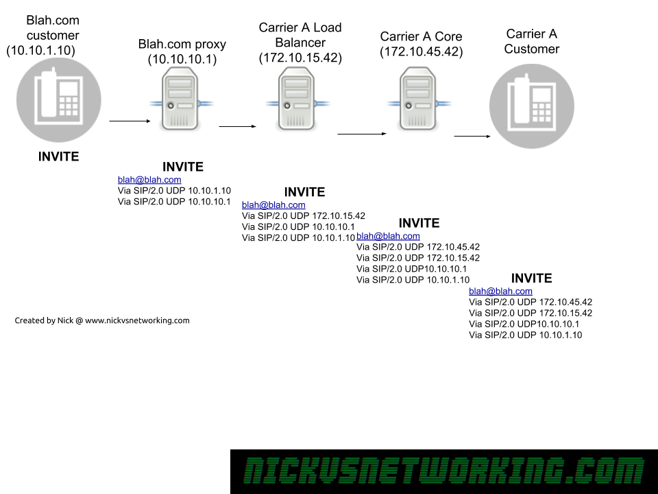
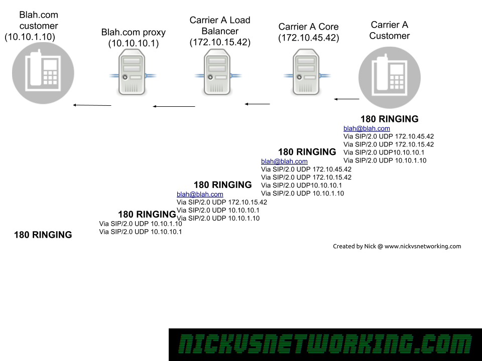
When a proxy has a response to send back to an endpoint, it can have multiple headers with routing information for how to get that response back to the endpoint that requested it.
So how to know which header to use on a new request?
Routing SIP Requests
Record-Route
If Route header is present (Like Record-Route) the proxy should use the contents of the Record-Route header to route the traffic back.
The Record-Route header is generally not the endpoint itself but another proxy, but that’s not an issue as the next proxy will know how to get to the endpoint, or use this same logic to know how to get it to the next proxy.
Contact
If no Route headers are present, the contact header is used.
The contact provides an address at which a endpoint can be contacted directly, this is used when no Record-Route header present.
From
If there is no Contact or Route headers the proxy should use the From address.
A note about Via
Via headers are only used in getting responses back to a client, and each hop removes it’s own IP on the response before forwarding it onto the next proxy.
This means the client doesn’t know all the Via headers that were on this SIP request, because by the time it gets back to the client they’ve all been removed one by one as it passed through each proxy.
A client can’t send a SIP request using Via’s as it hasn’t been through the proxies for their details to be added, so Via is only used in responding to a request, for example responding with a 404 to an INVITE, but cannot be used on a request itself (For example an INVITE).
If you, like me, spend a lot of time looking at SIP logs, sngrep is an awesome tool for debugging on remote machines. It’s kind of like if VoIP Monitor was ported back to the days of mainframes & minimal remote terminal GUIs.
Installation
It’s in the Repos for Debian and Ubuntu:
apt-get install sngrep
GUI Usage
sngrep can be used to parse packet captures and create packet captures by capturing off an interface, and view them at the same time.
We’ll start by just calling sngrep on a box with some SIP traffic, and waiting to see the dialogs appear.
Here we can see some dialogs, two REGISTERs and 4 INVITEs.
By using the up and down arrow keys we can select a dialog, hitting Enter (Return) will allow us to view that dialog in more detail:
Again we can use the up and down arrow keys to view each of the responses / messages in the dialog.
Hitting Enter again will show you that message in full screen, and hitting Escape will bring you back to the first screen.
From the home screen you can filter with F7, to find the dialog you’re interested in.
Command Line Parameters
One of the best features about sngrep is that you can capture and view at the same time.
As a long time user of TCPdump, I’d been faced with two options, capture the packets, download them, view them and look for what I’m after, or view it live with a pile of chained grep statements and hope to see what I want.
By adding -O filename.pcap to sngrep you can capture to a packet capture and view at the same time.
You can use expression matching to match only specific dialogs.
Kamailio’s permissions module is simple to use, and we’ve already touched upon it in the security section in our Kamailio 101 series, but I thought I’d go over some of it’s features in more detail.
At it’s core, Kamailio’s Permissions module is a series of Access Control Lists (ACLs) that can be applied to different sections of your config.
We can manage permissions to do with call routing, for example, is that source allowed to route to that destination.
We can manage registration permissions, for example, is this subnet allowed to register this username.
We can manage URI permissions & address permissions to check if a specific SIP URI or source address is allowed to do something.
We’ll touch on a simple IP Address based ACL setup in this post, but you can find more information in the module documentation itself.
The Setup
We’ll be using a database backend for this (MySQL), setup the usual way.
We’ll need to load the permissions module and setup it’s basic parameters, for more info on setting up the database side of things have a look here.
Next we’ll need to add some IPs, we could use Serimis for this, or a straight MySQL INSERT, but we’ll use kamctl to add them. (kamcmd can reload addresses but doesn’t currently have the functionality to add them)
The above example we added a two new address entries,
The first one added a new entry in group 250 of “10.8.203.139”, with a /32 subnet mask (Single IP), on port 5060 with the label “TestServer”,
The second one we added to group 200 was a subnet of 192.168.1.0 with a /24 subnet mask (255 IPs), on port 5060 with the label “OfficeSubnet”
On startup, or when we manually reload the addressTable, Kamailio grabs all the records and stores them in RAM. This makes lookup super fast, but the tradeoff is you have to load the entries, so changes aren’t immediate.
Let’s use Kamcmd to reload the entries and check their status.
kamcmd permissions.addressReload
kamcmd permissions.addressDump
kamcmd permissions.subnetDump
You should see the single IP in the output of the permissions.addressDump and see the subnet on the subnetDump:
Usage
It’s usage is pretty simple, combined with a simple nested if statement.
if (allow_source_address("200")) {
xlog("Coming from address group 200");
};
if (allow_source_address("250")) {
xlog("Coming from address group 250");
};
The above example just outputs to xlog with the address group, but we can expand upon this to give us our ACL service.
if (allow_source_address("200")) {
xlog("Coming from address group 200");
}else if (allow_source_address("250")) {
xlog("Coming from address group 250");
}else{
sl_reply("401", "Address not authorised");
exit;
}
If we put this at the top of our Kamailio config we’ll reply with a 401 response to any traffic not in address group 200 or 250.
If you’ve ever phoned a big company like a government agency or an ISP to get something resolved, and been transferred between person to person, having to start again explaining the problem to each of them, then you know how frustrating this can be.
If they stored information about your call that they could bring up later during the call, it’d make your call better.
If the big company, started keeping a record of the call that could be referenced as the call progresses, they’d be storing state for that call.
Let’s build on this a bit more,
You phone Big Company again, the receptionist answers and says “Thank you for calling Big Company, how many I direct your call?”, and you ask to speak to John Smith.
The receptionist puts you through to John Smith, who’s not at his desk and has setup a forward on his phone to send all his calls to reception, so you ring back at reception.
A stateful receptionist would say “Hello again, it seems John Smith isn’t at his desk, would you like me to take a message?”.
A stateless receptionist would say “Thank you for calling Big Company, how many I direct your call?”, and you’d start all over again.
Our stateful receptionist remembered something about our call, they remembered they’d spoken to you, remembered who you were, that you were trying to get to John Smith.
While our stateless receptionist remembered nothing and treated this like a new call.
In SIP, state is simply remembering something about that particular session (series of SIP messages).
SIP State just means bits of information related to the session.
Stateless SIP Proxy
A Stateless SIP proxy doesn’t remember anything about the messages (sessions), no state information is kept. As soon as the proxy forwards the message, it forgets all about it, like our receptionist who just forwards the call and doesn’t remember anything.
Going back to our Big Company example, as you can imagine, this is much more scaleable, you can have a pool of stateless receptionists, none of whom know who you are if you speak to them again, but they’re a lot more efficient because they don’t need to remember any state information, and they can quickly do their thing without looking stuff up or memorising it.
The same is true of a Stateless SIP proxy.
Stateless proxies are commonly used for load balancing, where you want to just forward the traffic to another destination (maybe using the Dispatcher module) and don’t need to remember anything about that session.
It sounds obvious, but because a Stateless SIP proxy it stateless it doesn’t store state, but that also means it doesn’t need to lookup state information or write it back, making it much faster and generally able to handle larger call loads than a stateful equivalent.
Dialog Stateful SIP Proxy
A dialog stateful proxy keeps state information for the duration of that session (dialog).
By dialog we mean for the entire duration on the call/session (called a dialog) from beginning to end, INVITE to BYE.
While this takes more resources, it means we can do some more advanced functions.
For example if we want to charge based on the length of a call/session, we’d need to store state information, like the Call-ID, the start and end time of the call. We can only do this with a stateful proxy, as a stateless proxy wouldn’t know what time the call started.
Also if we wanted to know if a user was on a call or not, a Dialog Stateful proxy knows there’s been a 200 OK, but no Bye yet, so knows if a user is on a call or not, this is useful for presence. We could tie this in with a NOTIFY so other users could know their status.
A Dialog Stateful Proxy is the most resource intensive, as it needs to store state for the duration of the session.
Transaction Stateful SIP Proxy
A transactional proxy keeps state until a final response is received, and then forgets the state information after the final response.
A Transaction Stateful proxy stores state from the initial INVITE until a 200 OK is received. As soon as the session is setup it forgets everything. This means we won’t have any state information when the BYE is eventually received.
While this means we won’t be able to do the same features as the Dialog Stateful Proxy, but you’ll find that most of the time you can get away with just using Transaction Stateful proxies, which are less resource intensive.
For example if we want to send a call to multiple carriers and wait for a successful response before connecting it to the UA, a Transactional proxy would do the trick, with no need to go down the Dialog Stateful path, as we only need to keep state until a session is successfully setup.
For the most part, SIP is focused on setting up sessions, and so is a Transaction Stateful Proxy.
Kamalio’s dialplan is a bit of a misleading title, as it can do so much more than just act as a dialplan.
At it’s core, it runs transformations. You feed it a value, if the value matches the regex Kamailio has it can either apply a transformation to that value or return a different value.
Adding to Config
For now we’ll just load the dialplan module and point it at our DBURL variable:
loadmodule "dialplan.so"
modparam("dialplan", "db_url", DBURL); #Dialplan database from DBURL variable
Restart Kamailio and we can get started.
Basics
Let’s say we want to take StringA and translate it in the dialplan module to StringB, so we’d add an entry to the database in the dialplan table, to take StringA and replace it with StringB.
Now we’ll fire up Kamailio, open kamcmd and reload the dialplan, and dump out the entries in Dialplan ID 1:
dialplan.reload dialplan.dump 1
You should see the output of what we just put into the database reflected in kamcmd:
Now we can test our dialplan translations, using Kamcmd again.
dialplan.translate 1 StringA
All going well Kamailio will match StringA and return StringB:
So we can see when we feed in String A, to dialplan ID 1, we get String B returned.
Database Structure
There’s a few fields in the database we populated, let’s talk about what each one does.
dpid
dpid = Dialplan ID. This means we can have multiple dialplans, each with a unique dialplan ID. When testing we’ll always need to specific the dialplan ID we’re using to make sure we’re testing with the right rules.
priority
Priorities in the dialplan allow us to have different weighted priorities. For example we might want a match all wildcard entry, but more specific entries with lower values. We don’t want to match our wildcard failover entry if there’s a more specific match, so we use priorities to run through the list, first we try and match the group with the lowest number, then the next lowest and so on, until a match is found.
match_op
match_op = Match Operation. There are 3 options:
0 – string comparison;
1 – regular expression matching (pcre);
2 – fnmatch (shell-like pattern) matching
In our first example we had match_op set to 0, so we exactly matched “StringA”. The real power comes from Regex Matching, which we’ll cover soon.
match_exp
match_exp = Match expression. When match_op is set to 0 this matches exactly the string in match_exp, when match_op is set to 1 this will contain a regular expression to match.
match_len
match_len = Match Length. Allows you to match a specific length of string.
subst_exp
subst_exp = Substitute Expression. If match_op is set to 0 this will contain be empty If match_op is 1 this will contain the same as match_exp.
repl_exp
repl_exp = replacement expression. If match_op is set to 0 this will contain the string to replace the matched string.
If match_op is set to 1 this can contain the regex group matching (\1, \2, etc) and any suffixes / prefixes (for example 61\1 will prefix 61 and add the contents of matched group 1).
attrs
Attributes. Often used as a descriptive name for the matched rule.
Getting Regex Rules Setup
The real power of the dialplan comes from Regular Expression matching. Let’s look at some use cases and how to solve them with Dialplans.
Note for MySQL users: MySQL treats \ as the escape character, but we need it for things like matching a digit in Regex (that’s \d ) – So keep in mind when inserting this into MySQL you may need to escale the escape, so to enter \d into the match_exp field in MySQL you’d enter \\d – This has caught me in the past!
The hyperlinks below take you to the examples in Regex101.com so you can preview the rules and make sure it’s matching what it should prior to putting it into the database.
Speed Dial
Let’s start with a simple example of a speed dial. When a user dials 101 we want to translate it to a PSTN number of 0212341234.
Without Regex this looks very similar to our first example, we’ve just changed the dialplan id (dpid) and the match_op and repl_exp.
Once we’ve added it to the database we’ll reload the dialplan module and dump dialplan 2 to check it all looks correct:
Now let’s test what happens if we do a dialplan translate on dialplan 2 with 101.
Tip: If you’re testing a dialplan and what you’re matching is a number, add s: before it so it matches as a number, not a string.
dialplan.translate 2 s:101
Here we can see we’ve matched 101 and the output is the PSTN number we wanted to translate too.
Interoffice Dial
Let’s take a slightly more complex example. We’ve got an office with two branches, office A’s phone numbers start with 0299991000, and they have 4 digit extensions, so extension 1002 maps to 0299991002, 0299991003 maps to extension 1003, etc.
From Office B we want to be able to just dial the 4 digit extensions of a user in Office A.
This means if we receive 1003 we need to prefix 029999 + 10003.
Then another reload and translate, and we can test again.
dialplan.reload dialplan.translate 3 s:1003 (Translates to 0299991003) dialplan.translate 3 s:1101 (no translation)
Interoffice Dial Failure Route (Priorities)
So let’s say we’ve got lots of branches configured like this, and we don’t want to just get “No Translation” if a match isn’t found, but rather send it to a specific destination, say reception on extension 9000.
So we’ll keep using dpid 3 and we’ll set all our interoffice dial rules to have priority 1, and we’ll create a new entry to match anything 4 digits long and route it to the switch.
This entry will have a higher priority value than the other so will only mach if nothing else with a lower priority number matches.
Now we’ve got Group 2 containing the data we need, we just need to prefix 613 in front of it.
Let’s go ahead an put this into the database, with dialplan ID set to 4, match_op set to 1 (for regex)
Then we’ll do a dialplan reload and a dialplan dump for dialplan ID 4 to check everything is there:
Now let’s put it to the test.
dialplan.translate 4 s:0399999999
Bingo, we’ve matched the regex, and returned 613 and the output of Regex Match group 2. (999999999)
Let’s expand upon this a bit, a valid 0NSN number could also be a mobile (0400000000) or a local number in a different area code (0299999999, 0799999999 or 0899999999).
We could create a dialplan entry for each, our we could expand upon our regex to match all these scenarios.
Now let’s update the database so that once we’re matched we’ll just prefix 61 and the output of regex group 2.
Again we’ll do a dialplan reload and a dialplan dump to check everything.
Now let’s run through our examples to check they correctly translate:
And there you go, we’re matched and the 0NSN formatted number was translated to E.164.
Adding to Kamailio Routing
So far we’ve just used kamcmd’s dialplan.translate function to test our dialplan rules, now let’s actually put them into play.
For this we’ll use the function
dp_translate(id, [src[/dest]])
dp_translate is dialplan translate. We’ll feed it the dialplan id (id) and a source variable and destination variable. The source variable is the equivalent of what we put into our kamcmd dialplan.translate, and the destination is the output.
In this example we’ll rewrite the Request URI which is in variable $rU, we’ll take the output of $rU, feed it through dialplan translate and save the output as $rU (overwrite it).
Let’s start with the Speed Dial example we setup earlier, and put that into play.
if(method=="INVITE"){
xlog("rU before dialplan translation is $rU");
dp_translate("2", "$rU/$rU");
xlog("rU after dialplan translation is $rU");
}
The above example will output our $rU variable before and after the translation, and we’re using Dialplan ID 2, which we used for our speed dial example.
So let’s send an INVITE from our Softphone to our Kamailio instance with to 101, which will be translated to 0212341234.
Before we do we can check it with Kamcmd to see what output we expect:
dialplan.translate 2 s:101
Let’s take a look at the out put of Syslog when we call 101.
But our INVITE doesn’t actually go anywhere, so we’ll add it to our dispatcher example from the other day so you can see it in action, we’ll relay the INVITE to an active Media Gateway, but the $rU will change.
if(method=="INVITE"){
xlog("rU before dialplan translation is $rU");
dp_translate("2", "$rU/$rU");
xlog("rU after dialplan translation is $rU");
ds_select_dst(1, 12);
t_on_failure("DISPATCH_FAILURE");
route(RELAY);
}
Let’s take a look at how the packet captures now look:
UA > Kamailio: INVITE sip:101@kamailio SIP/2.0 Kamailio > UA: SIP/2.0 100 trying -- your call is important to us Kamailio > MG1: INVITE sip:0212341234@MG1 SIP/2.0
So as you can see we translated 101 to 0212341234 based on the info in dialplan id 2 in the database.
That’s all well and good if we dial 101, but what if we dial 102, there’s no entry in the database for 102, as we see if we try it in Kamcmd:
dialplan.translate 2 s102
And if we make a call to 102 and check syslog:
rU before dialplan translation is 102 rU after dialplan translation is 102
Let’s setup some logic so we’ll respond with a 404 “Not found in Dialplan” response if the dialplan lookup doesn’t return a result:
if(dp_translate("2", "$rU/$rU")){
xlog("Successfully translated rU to $rU using dialplan ID 2");
}else{
xlog("Failed to translate rU using dialplan ID 2");
sl_reply("404", "Not found in dialplan");
exit;
}
By putting dp_translate inside an if we’re saying “if dp_translate is successful then do {} and the else will be called if dp_translate wasn’t successful.
Let’s take a look at a call to 101 again.
UA > Kamailio: INVITE sip:101@kamailio SIP/2.0 Kamailio > UA: SIP/2.0 100 trying -- your call is important to us Kamailio > MG1: INVITE sip:0212341234@MG1 SIP/2.0
Still works, and a call to 102 (which we don’t have an entry for in the dialplan).
UA > Kamailio: INVITE sip:102@kamailio SIP/2.0 Kamailio > UA: SIP/2.0 404 Not found in dialplan
Hopefully by now you’ve got a feel for the dialplan module, how to set it up, debug it, and use it.
When a final response, like a 200 OK, or a 404, etc, is sent, the receiving party acknowledges that it received this with an ACK.
By provisional responses, such as 180 RINGING, are not acknowledged, this means we have no way of knowing for sure if our UAC received the provisional response.
The issues start to arise when using SIP on Media Gateways or inter-operating with SS7 / ISUP / PSTN, all of which have have guaranteed delivery of a RINGING response, but SIP doesn’t. (Folks from the TDM world will remember ALERTING messages)
The IETF saw there was in some cases, a need to confirm these provisional responses were received, and so should have an ACK.
They created the Reliability of Provisional Responses in the Session Initiation Protocol (SIP) under RFC3262 to address this.
This introduced the Provisional Acknowledgement (PRACK) and added the 100rel extension to Supported / Requires headers where implemented.
This means when 100rel extension is not used a media gateway that generates a 180 RINGING or a 183 SESSION PROGRESS response, sends it down the chain of proxies to our endpoint, but could be lost anywhere along the chain and the media gateway would never know.
When the 100rel extension is used, our media gateway generates a 18x response, and forwards it down the chain of proxies to our endpoint, and our 18x response now also includes a RSeq which is a reliable sequence number.
The endpoint receives this 18x response and sends back a Provisional Acknowledgement or PRACK, with a Rack header (Reliable Acknowledgement) header with the same value as the RSeq of the received 18x response.
The media gateway then sends back a 200 OK for the PRACK.
In the above example we see a SIP call to a media gateway,
The INVITE is sent from the caller to the Media Gateway via the Proxy. The caller has included value “100rel” in the Supported: header, showing support for RFC3262.
The Media gateway looks at the destination and knows it needs to translate this SIP message to a different a different protocol. Our media gateway is translating our SIP INVITE message into it’s Sigtran equivalent (IAM), and forward it on, which it does, sending an IAM (Initial Address Message) via Sigtran.
When the media gateways gets confirmation the remote destination is ringing via Sigtran (ACM ISUP message), it translates that to it’s SIP equivalent message which is, 180 RINGING.
The Media Gateway set a reliable sequence number on this provisional response, contained in the RSeq header.
This response is carried through the proxy back to the caller, who signals back to the media gateway it got the 180 RINGING message by sending a PRACK (Provisional ACK) with the same RSeq number.
The Dispatcher module is used to offer load balancing functionality and intelligent dispatching of SIP messages.
Let’s say you’ve added a second Media Gateway to your network, and you want to send 75% of traffic to the new gateway and 25% to the old gateway, you’d use the load balancing functionality of the Dispatcher module.
Let’s say if the new Media Gateway goes down you want to send 100% of traffic to the original Media Gateway, you’d use the intelligent dispatching to detect status of the Media Gateway and manage failures.
These are all problems the Dispatcher Module is here to help with.
Before we get started….
Your Kamailio instance will need:
Installed and running Kamailio instance
Database configured and tables created (We’ll be using MySQL but any backed is fine)
kamcmd & kamctl working (kamctlrc configured)
Basic Kamailio understanding
The Story
So we’ve got 4 players in this story:
Our User Agent (UA) (Softphone on my PC)
Our Kamailio instance
Media Gateway 1 (mg1)
Media Gateway 2 (mg2)
Our UA will make a call to Kamailio. (Send an INVITE)
Kamailio will keep track of the up/down status of each of the media gateways, and based on rules we define pick one of the Media Gateways to forward the INVITE too.
The Media Gateways will playback “Media Gateway 1” or “Media Gateway 2” depending on which one we end up talking too.
Configuration
Parameters
You’ll need to load the dispatcher module, by adding the below line with the rest of your loadmodules:
loadmodule "dispatcher.so"
Next we’ll need to set the module specific config using modparam for dispatcher:
modparam("dispatcher", "db_url", DBURL) #Use DBURL variable for database parameters
modparam("dispatcher", "ds_ping_interval", 10) #How often to ping destinations to check status
modparam("dispatcher", "ds_ping_method", "OPTIONS") #Send SIP Options ping
modparam("dispatcher", "ds_probing_threshold", 10) #How many failed pings in a row do we need before we consider it down
modparam("dispatcher", "ds_inactive_threshold", 10) #How many sucessful pings in a row do we need before considering it up
modparam("dispatcher", "ds_ping_latency_stats", 1) #Enables stats on latency
modparam("dispatcher", "ds_probing_mode", 1) #Keeps pinging gateways when state is known (to detect change in state)
Most of these are pretty self explanatory but you’ll probably need to tweak these to match your environment.
Destination Setup
Like the permissions module, dispatcher module has groups of destinations.
For this example we’ll be using dispatch group 1, which will be a group containing our Media Gateways, and the SIP URIs are sip:mg1:5060 and sip:mg2:5060
From the shell we’ll use kamctl to add a new dispatcher entry.
You can use kamctl to show you the database entries:
kamctl dispatcher show
A restart to Kamailio will make our changes live.
Destination Status / Control
Checking Status
Next up we’ll check if our gateways are online, we’ll use kamcmd to show the current status of the destinations:
kamcmd dispatcher.list
Here we can see our two media gateways, quick response times to each, and everything looks good.
Take a note of the FLAGS field, it’s currently set to AP which is good, but there’s a few states:
AP – Active Probing – Destination is responding to pings & is up
IP – Inactive Probing – Destination is not responding to pings and is probably unreachable
DX – Destination is disabled (administratively down)
AX – Looks like is up or is coming up, but has yet to satisfy minimum thresholds to be considered up (ds_inactive_threshold)
TX – Looks like or is, down. Has stopped responding to pings but has not yet satisfied down state failed ping count (ds_probing_threshold)
Adding Additional Destinations without Restarting
If we add an extra destination now, we can add it without having to restart Kamailio, by using kamcmd:
kamcmd dispatcher.reload
There’s some sanity checks built into this, if the OS can’t resolve a domain name in dispatcher you’ll get back an error:
Administratively Disable Destinations
You may want to do some work on one of the Media Gateways and want to nicely take it offline, for this we use kamcmd again:
kamcmd dispatcher.set_state dx 1 sip:mg1:5060
Now if we check status we see MG1’s status is DX:
Once we’re done with the maintenance we could force it into the up state by replacing dx with ap.
It’s worth noting that if you restart Kamailio, or reload dispatcher, the state of each destination is reset, and starts again from AX and progresses to AP (Up) or IP (Down) based on if the destination is responding.
Routing using Dispatcher
The magic really comes down to single simple line, ds_select_dst();
The command sets the destination address to an address from the pool of up addresses in dispatcher.
You’d generally give ds_select_dst(); two parameters, the first is the destination set, in our case this is 1, because all our Media Gateway destinations are in set ID 1. The next parameter is is the algorithm used to work out which destination from the pool to use for this request.
Some common entries would be random, round robin, weight based or priority value.
In our example we’ll use a random selection between up destinations in group 1:
if(method=="INVITE"){
ds_select_dst(1, 4); #Get a random up destination from dispatcher
route(RELAY); #Route it
}
Now let’s try and make a call:
UA > Kamailio: SIP: INVITE sip:1111111@Kamailio SIP/2.0
Kamailio > UA: SIP: SIP/2.0 100 trying -- your call is important to us
And bingo, we’re connected to a Media Gateway 1. If I try it again I’ll get MG2, then MG1, then MG2, as we’re using round robin selection.
Destination Selection Algorithm
We talked a little about the different destination select algorithm, let’s dig a little deeper into the common ones, this is taken from the Dispatcher documentation:
“0” – hash over callid
“4” – round-robin (next destination).
“6” – random destination (using rand()).
“8” – select destination sorted by priority attribute value (serial forking ordered by priority).
“9” – use weight based load distribution.
“10” – use call load distribution.
“12” – dispatch to all destination in setid at once
For select destination sorted by priority (8) to work you need to include a priority, you can do this when adding the dispatcher entry or after the fact by editing the data. In the below example if MG1 is up, calls will always go to MG1, if MG1 is down it’ll go to the next highest priority (MG2).
For use weight based load distribution (9) to work, you’ll need to set a weight as well, this is similar to priority but allows you to split load, for example you could put weight=25 on a less powerful or slower destination, and weight=75 for a faster or more powerful destination, so the better destination gets 75% of traffic and the other gets 25%. (You don’t have to do these to add to 100%, I just find it easier to think of them as percentages).
use call load distribution (10) allows you to evenly split the number of calls to each destination. This could be useful if you’ve got say 2 SIP trunks with x channels on each trunk, but only x concurrent calls allowed on each. Like adding a weight you need to set a duid= value with the total number of calls each destination can handle.
dispatch to all destination in setid at once (12) allows you to perform parallel branching of your call to all the destinations in the address group and whichever one answers first will handle the call. This adds a lot of overhead, as for each destination you have in that set will need a new dialog to be managed, but it sure is quick for the user. The other major issue is let’s say I have three carriers configured in dispatcher, and I call a landline.
That landline will receive three calls, which will ring at the same time until the called party answers one of the calls. When they do the other two calls will stop ringing. This can get really messy.
Managing Failure
Let’s say we try and send a call to one of our Media Gateways and it fails, we could forward that failure response to the UA, or, better yet, we could try on another Media Gateway.
Let’s set a priority of 10 to MG1 and a priority of 5 to MG2, and then set MG1 to reject the call.
We’ll also need to add a failure route, so let’s tweak our code:
It’s no great secret I collect old phone stuff, I got this Melbourne made PMBX (Private Manual Branch Exchange) a while back, and I finally got around to doing something with it.
I’ve cleaned all the relays, got all the electronics happy (still need to replace the ring generator), taken everything out, sanded it, varnished it, 3D printed replacement knobs, cleaned the glass and got it looking all schmick.
Before
During
After
Glass replaced, contacts cleaned, wooden case taken apart, treated for boras, sanded and stained.
Next up fit all the 3D printed knobs, and repaint all the switch assemblies
Want more telecom goodness?
I have a good old fashioned RSS feed you can subscribe to.