A lot of countries have a single point of contact for emergency services; in Europe you’d call 112 in an emergency, 000 in Australia or 911 in the US. Calling this number in the country will get you the emergency services.
This means a caller can order an ambulance for smoke inhalation, and the fire brigade, in one call.
But that’s not the case in every country; many countries don’t have one number for theemergency services, they’ve got multiple; a phone number for police, a different number for fire brigade and a different number for an ambulance.
For example, in Brazil if you need the police, you call 190, while a for example, uses 193 as the emergency number for the fire department, the police can be reached at 190 or 191 depending on if it’s road policing or general, and medical emergencies are covered by 192. Other countries have similar setups.
This is all well and good if you’re in Brazil, and you call 192 for an ambulance, the phone sends a SIP INVITE with a Request URI of sip:[email protected], because we can put a rule into our E-CSCF to say if the number is 192 to route it to the answer point for ambulances – But that’s not often the case on emergency calls.
In IMS, handsets generally detect the number dialed is on the Emergency Calling Code (ECC) list from the USIM Card.
The use of the ECC list means the phone knows this is an emergency call, and this is really important. For countries that use AML this can trigger sending of the AML SMS that process, and Emergency Calls should always be allowed to be made, even without credit, a valid SIM card, or even a SIM in the phone at all.
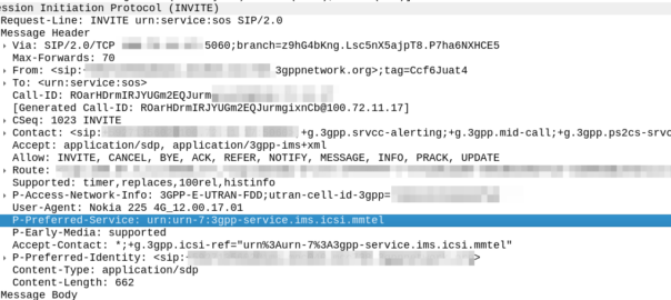
But this comes with a cost; when a user dials 911, the phones doesn’t (generally) send a call to sip:[email protected] like it would with any other dialled number, but rather the SIP INVITE is sent to urn:service:sos which will be routed to the PSAP by the E-CSCF. When a call comes through to these URNs they’re given top priority in the network
This is all well and good in a country where it doesn’t matter which emergency service you called, because all emergency calls route to a single PSAP, but in a country with multiple numbers, it’s really important when you call and ambulance, your call doesn’t get routed to animal control.
That means the phone has to look at what emergency number you’ve dialed, and map the URN it sends the call to to match what you’ve actually requested.
Recently we’ve been helping an operator in a country with a numbering plan like this, and we’ve been finding the limits of the standards here. So let’s start by looking at what the standards state:
IMS Emergency Calling is governed by TS 103.479 which in turn delegates to IETF RFC 5031, but for the calling number to URN translation, it’s pretty quiet.
Let’s look at what RFC 5031 allows for URNs:
urn:service:sos.ambulance
urn:service:sos.animal-control
urn:service:sos.fire
urn:service:sos.gas
urn:service:sos.marine
urn:service:sos.mountain
urn:service:sos.physician
urn:service:sos.poison
urn:service:sos.police
The USIM’s Emergency Calling Codes EF would be the perfect source of this data; for each emergency calling code defined, you’ve got a flag to indicate what it’s for, here’s what we’ve got available on the SIM Card:
Bit 1 Police
Bit 2 Ambulance
Bit 3 Fire Brigade
Bit 4 Marine Guard
Bit 5 Mountain Rescue
Bit 6 manually initiated eCall
Bit 7 automatically initiated eCall
Bit 8 is spare and set to “0”
So these could be mapped pretty easily you’d think, so if the call is made to an Emergency Calling Code flagged with Bit 4, the URN would go to urn:service:sos.mountain.
Alas from our research, we’ve found most OEMs send calls to the generic urn:service:sos, regardless of the dialled number and the ECC flags that are set on the SIM for that number.
One of the big chip vendors sends calls to an ECC flagged as Ambulance to urn:service:sos.fire, which is totally infuriating, and we’ve had to put a rule in our E-CSCF to handle this if the User Agent is set to one of their phones.
Is there room for improvement here? For sure! Emergency calling is super important, and time is of the essence, while animal control can probably transfer you to an ambulance, an emergency is by very nature time sensitive, and any time wasted can lead to worse outcomes.
While carrier bundles from the OEMs can handle this, the global ability to take any phone, from any country and call an emergency number is so important, that relying on a country-by-country approach here won’t suffice.
What could we do as an industry to address this?
Acknowledging that not all countries have a single point of contact for emergency service, introducing a simple mechanism in the UE SIP message to indicate what number (Emergency Calling Code) the user actually dialled would be invaluable here.
URNs are important, but knowing the dialed number when it comes to PSAP routing, is so important – This wouldn’t even need to be its own SIP header, it could just be thrown into the Contact header as another parameter.
Highly developed markets are often the first to embrace new tech (for us this means VoLTE and VoNR), but this means that these issues seen by less developed markets won’t appear until long after the standard has been set in stone, and often countries like this aren’t at the table of the standards bodies to discuss such requirements.
This easy, reasonable update to the standard, has the potential to save lives, and next time this comes up in a working group I’ll be advocating for a change.
The other day I found myself banging my head on the table to diagnose an issue with Ringback tone on an SS7 link and the IMS.
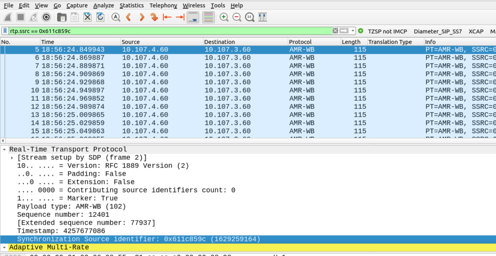
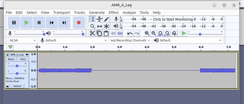
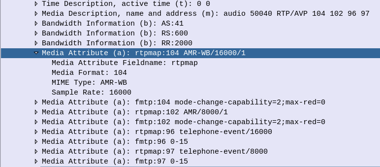
On the IMS side, no RBT was heard, but I could see the Media Gateway was sending RTP packets to the TAS, and the TAS was sending it to the UE, but was there actual content in the RTP packets or was it just silence?
If this was PCM / G711 we’d be able to just playback in Wireshark, but alas we can’t do this for the AMR codec.
Filter the RTP stream out in Wireshark
Inside Wireshark I filtered each of the audio streams in one direction (one for the A-Party audio and one for the B-Party audio)
Then I needed to save each of the streams as a separate PCAP file (Not PCAPng).
Advanced Mobile Location (AML) is being rolled out by a large number of mobile network operators to provide accurate caller location to emergency services, so how does it work, what’s going on and what do you need to know?
Recently we’ve been doing a lot of work on emergency calling in IMS, and meeting requirements for NG-112 / e911, etc.
This led me to seeing my first Advanced Mobile Location (AML) SMS in the wild.
For those unfamiliar, AML is a fancy text message that contains the callers location, accuracy, etc, that is passed to emergency services when you make a call to emergency services in some countries.
It’s sent automatically by your handset (if enabled) when making a call to an emergency number, and it provides the dispatch operator with your location information, including extra metadata like the accuracy of the location information, height / floor if known, and level of confidence.
Google has their own version of AML called ELS, which they claim is supported on more than 99% of Android phones (I’m unclear on what this means for Harmony OS or other non-Google backed forks of Android), and Apple support for AML starts from iOS 11 onwards, meaning it’s supported on iPhones from the iPhone 5S onards,.
Call Flow
When a call is made to the PSAP based on the Emergency Calling Codes set on the SIM card or set in the OS, the handset starts collecting location information. The phone can pull this from a variety of sources, such as WiFi SSIDs visible, but the best is going to be GPS or one of it’s siblings (GLONASS / Galileo).
Once the handset has a good “lock” of a location (or if 20 seconds has passed since the call started) it bundles up all of this information the phone has, into an SMS and sends it to the PSAP as a regular old SMS.
The routing from the operator’s SMSc to the PSAP, and the routing from the PSAP to the dispatcher screen of the operator taking the call, is all up to implementation. For the most part the SMS destination is the emergency number (911 / 112) but again, this is dependent on the country.
Inside the SMS
To the user, the AML SMS is not seen, in fact, it’s actually forbidden by the standard to show in the “sent” items list in the SMS client.
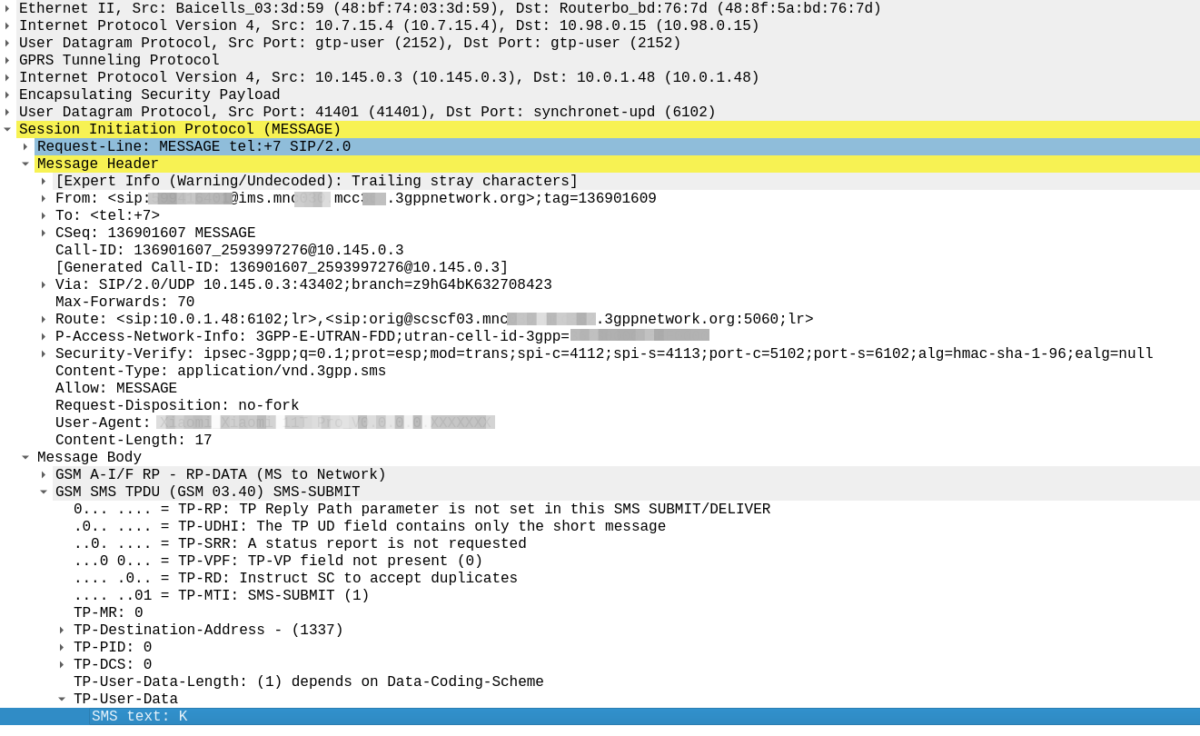
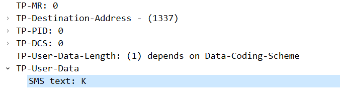
On the wire, the SMS looks like any regular SMS, it can use GSM7 bit encoding as it doesn’t require any special characters.
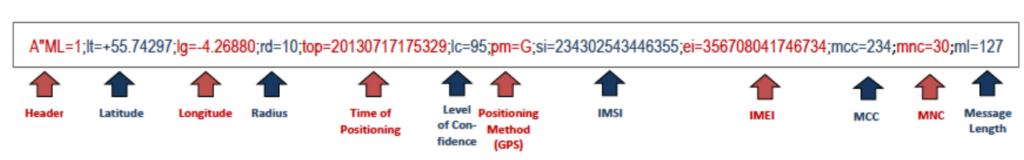
Each attribute is a key / value pair, with semicolons (;) delineating the individual attributes, and = separating the key and the value.
If you’ve got a few years of staring at Wireshark traces in Hex under your belt, then this will probably be pretty easy to get the gist of what’s going on, we’ve got the header (A”ML=1″) which denotes this is AML and the version is 1.
After that we have the latitude (lt=), longitude (lg=), radius (rd=), time of positioning (top=), level of confidence (lc=), positioning method (pm=) with G for GNSS, W for Wifi signal, C for Cell or N for a position was not available, and so on.
AML outside the ordinary
Roaming Scenarios
If an emergency occurs inside my house, there’s a good chance I know the address, and even if I don’t know my own address, it’s probably linked to the account holder information from my telco anyway.
AML and location reporting for emergency calls is primarily relied upon in scenarios where the caller doesn’t know where they’re calling from, and a good example of this would be a call made while roaming.
If I were in a different country, there’s a much higher likelihood that I wouldn’t know my exact address, however AML does not currently work across borders.
The standard suggests disabling SMS when roaming, which is not that surprising considering the current state of SMS transport.
Without a SIM?
Without a SIM in the phone, calls can still be made to emergency services, however SMS cannot be sent.
That’s because the emergency calling standards for unauthenticated emergency calls, only cater for
This is a limitation however this could be addressed by 3GPP in future releases if there is sufficient need.
HTTPS Delivery
The standard was revised to allow HTTPS as the delivery method for AML, for example, the below POST contains the same data encoded for use in a HTTP transaction:
Implementation of this approach is however more complex, and leads to little benefit.
The operator must zero-rate the DNS, to allow the FQDN for this to be resolved (it resolves to a different domain in each country), and allow traffic to this endpoint even if the customer has data disabled (see what happens when your handset has PS Data Off ), or has run out of data.
Due to the EU’s stance on Net Neutrality, “Zero Rating” is a controversial topic that means most operators have limited implementation of this, so most fall back to SMS.
Other methods for sharing location of emergency calls?
In some upcoming posts we’ll look at the GMLC used for E911 Phase 2, and how the network can request the location from the handset.
I had a question recently on LinkedIn regarding how to preference Voice over WiFi traffic so that a network engineer operating the WiFi network can ensure the best quality of experience for Voice over WiFi.
Voice over WiFi is underpinned by the ePDG – Evolved Packet Data Gateway (this is a fancy IPsec tunnel we authenticate to using the SIM to drop our traffic into the P-CSCF over an unsecured connection). To someone operating a WiFi network, the question is how do we prioritise the traffic to the ePDGs and profile it?
ePDGs can be easily discovered through a simple DNS lookup, once you know the Mobile Network Code and Mobile Country code of the operators you want to prioritise, you can find the IPs really easily.
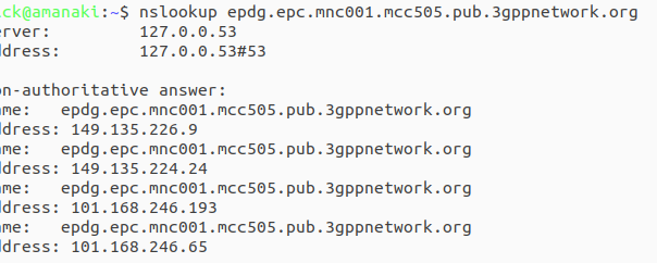
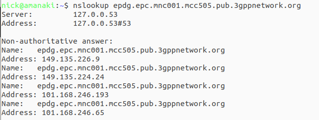
ePDG addresses take the form epdg.epc.mncXXX.mccYYY.pub.3gppnetwork.org so let’s look at finding the IPs for each of these for the operators in a country:
The first step is nailing down the mobile network code and mobile country codes of the operators you want to target, Wikipedia is a great source for this information. Here in Australia we have the Mobile Country Code 505 and the big 3 operators all support Voice over WiFi, so let’s look at how we’d find the IPs for each. Telstra has mobile network code (MNC) 01, in 3GPP DNS we always pad network codes to 3 digits, so that’ll be 001, and the mobile country code (MCC) for Australia is 505. So to find the IPs for Telstra we’d run an nslookup for epdg.epc.mnc001.mcc505.pub.3gppnetwork.org – The list of IPs that are returned, are the IPs you’ll see Voice over WiFi traffic going to, and the IPs you should provide higher priority to:
The same rules apply in other countries, you’d just need to update the MNC/MCC to match the operators in your country, do an nslookup and prioritise those IPs.
Generally these IPs are pretty static, but there will need to be a certain level of maintenance required to keep this list up to date by rechecking.
We recently added support in PyHSS for fixed line SIP subscribers to attach to the IMS.
Traditional telecom operators are finding their fixed line network to be a bit of a money pit, something they’re required to keep operating to meet regulatory obligations, but the switches are sitting idle 99% of the time. As such we’re seeing more and more operators move fixed line subs onto their IMS.
This new feature means we can use PyHSS to serve as the brains for a fixed network, as well as for mobile, but there’s one catch – How we authenticate subscribers changes.
Most banks of line cards in a legacy telecom switches, or IP Phones, don’t have SIM slots to allow us to authenticate, so instead we’re forced to fallback to what they do support.
Unfortunately for the most part, what is supported by these IP phones or telecom switches is SIP MD5 Digest Authentication.
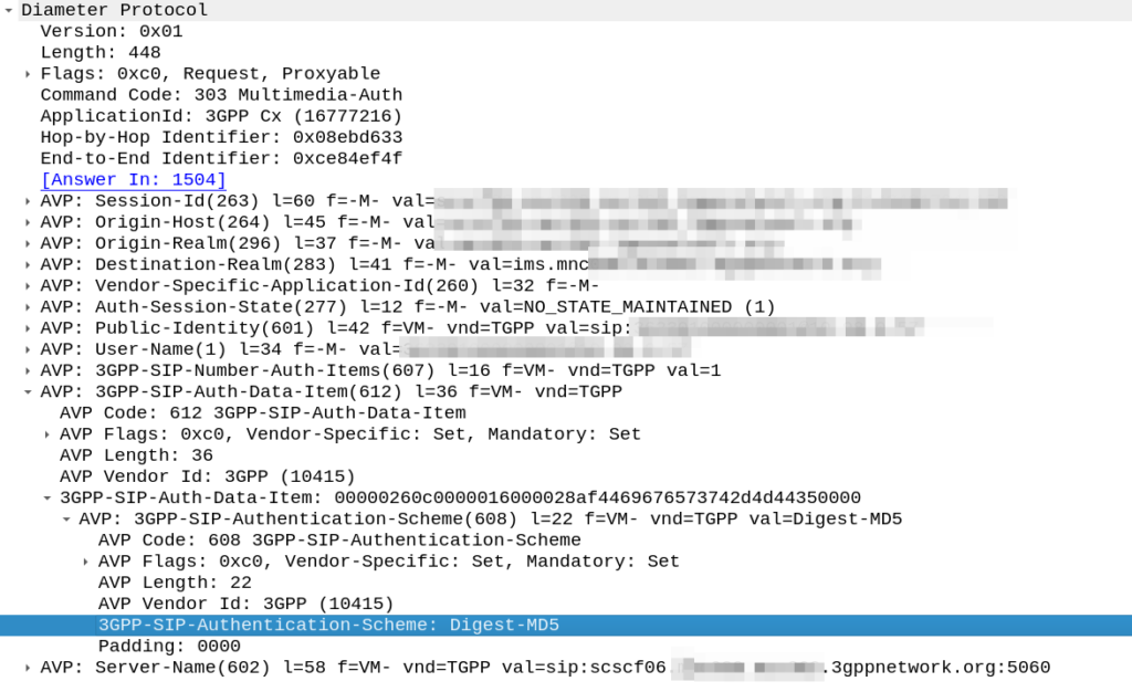
The Nonce is generated by the HSS and put into the Multimedia-Authentication-Answer, along with the subscriber’s password and sent in the clear to the S-CSCF.
The HSS then generates the the Multimedia-Auth Answer, it generates a nonce (in the 3GPP-SIP-Authenticate / 609 AVP) and sends the Subscriber’s password in the 3GPP-SIP-Authorization (610) AVP in response back to the S-CSCF.
I would have thought a better option would be for the HSS to generate the Nonce and Digest, and then the S-CSCF to just send the Nonce to the Sub and compare the returned Digest from the Sub against the expected Digest from the HSS, but it would limit flexibility (realm adaptation, etc) I guess.
The UE/UA (I guess it’s a UA in this context as it’s not a mobile) then generates its own Digest from the Nonce and sends it back to the S-CSCF via the P-CSCF.
The S-CSCF compares the received Digest response against the one it generated, and if the two match, the sub is authenticated and allowed to attach onto the network.
In the past I had my iFCs setup to look for the P-Access-Network-Info header to know if the call was coming from the IMS, but it wasn’t foolproof – Fixed line IMS subs didn’t have this header.
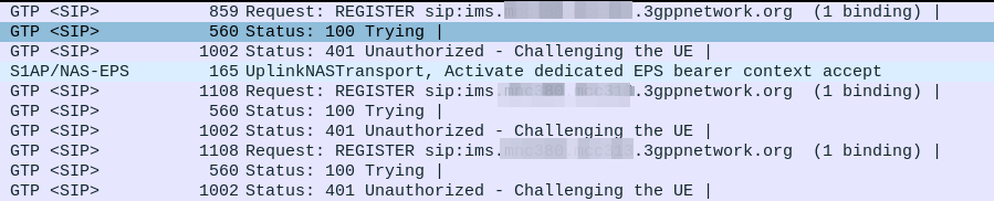
Everything was working on the IMS, then I go to bed, the next morning I fire up the test device and it just won’t authenticate to the IMS – The S-CSCF generated a 401 in response to the REGISTER, but the next REGISTER wouldn’t pass.
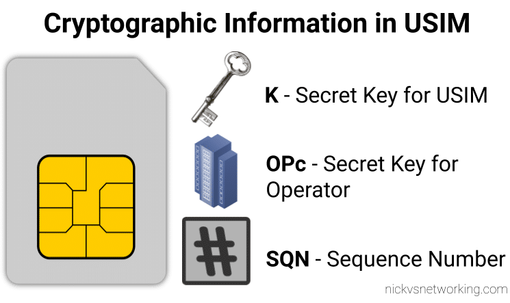
When we generate the vectors (for IMS auth and standard auth) one of the inputs to generate the vectors is the Sequence Number or SQN.
This SQN ticks over like an odometer for the number of times the SIM / HSS authentication process has been performed.
There is some leeway in the SQN – It may not always match between the SIM and the HSS and that’s to be expected. When the MME sends an Authentication-Information-Request it can ask for multiple vectors so it’s got some in reserve for the next time the subscriber attaches, and that’s allowed.
But there are limits to how far out our SQN can be, and for good reason – One of the key purposes for the SQN is to protect against replay attacks, where the same vector is replayed to the UE. So the SQN on the HSS can be ahead of the SIM (within reason), but it can’t be behind – Odometers don’t go backwards.
So the issue was with the SQN on the SIM being out of Sync with the SQN in the IMS, how do we know this is the case, and how do we fix this?
Well there is a resync mechanism so the SIM can securely tell the HSS what the current SQN it is using, so the HSS can update it’s SQN.
When verifying the AUTN, the client may detect that the sequence numbers between the client and the server have fallen out of sync. In this case, the client produces a synchronization parameter AUTS, using the shared secret K and the client sequence number SQN. The AUTS parameter is delivered to the network in the authentication response, and the authentication can be tried again based on authentication vectors generated with the synchronized sequence number.
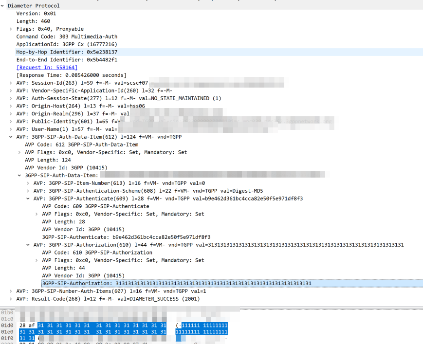
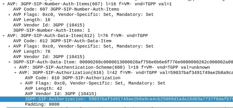
In our example we can tell the sub is out of sync as in our Multimedia Authentication Request we see the SIP-Authorization AVP, which contains the AUTS (client synchronization parameter) which the SIM generated and the UE sent back to the S-CSCF. Our HSS can use the AUTS value to determine the correct SQN.
SIP-Authorization AVP in the Multimedia Authentication Request means the SQN is out of Sync and this AVP contains the RAND and AUTN required to Resync
Note: The SIP-Authorization AVP actually contains both the RAND and the AUTN concatenated together, so in the above example the first 32 bytes are the AUTN value, and the last 32 bytes are the RAND value.
So the HSS gets the AUTS and from it is able to calculate the correct SQN to use.
Then the HSS just generates a new Multimedia Authentication Answer with a new vector using the correct SQN, sends it back to the IMS and presto, the UE can respond to the challenge normally.
Recently I had a strange issue I thought I’d share.
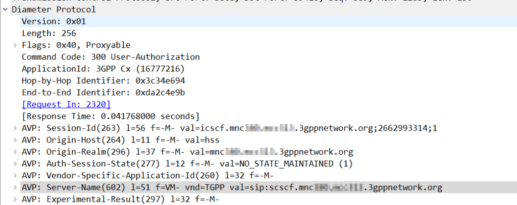
Using Kamailio as an Interrogating-CSCF, Kamailio was getting the S-CSCF details from the User-Authorization-Answer’s “Server-Name” (602) AVP.
The value was set to:
sip:scscf.mnc001.mcc001.3gppnetwork.org:5060
But the I-CSCF was only looking up A-Records for scscf.mnc001.mcc001.3gppnetwork.org, not using DNS-SRV.
The problem? The Server-Name I had configured as a full SIP URI in PyHSS including the port, meant that Kamailio only looks up the A-Record, and did not do a DNS-SRV lookup for the domain.
Dropping the port number saw all those delicious SRV records being queried.
Something to keep in mind if you use S-CSCF pooling with a Kamailio based I-CSCF, if you want to use SRV records for load balancing / traffic sharing, don’t include the port, and if instead you want it to go to the specified host found by an A-record, include the port.
If you’ve ever received an SMS from your operator, and the sender was the Operator name for example, you may be left wondering how it’s done.
In IMS you’d think this could be quite simple – You’d set the From header to be the name rather than the MSISDN, but for most SMSoIP deployments, the From header is ignored and instead the c header inside the SMS body is used.
So how do we get it to show text?
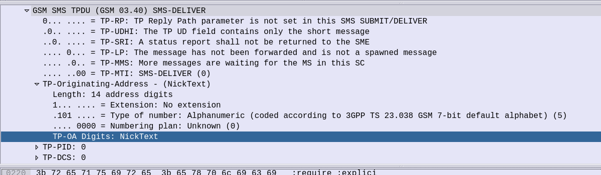
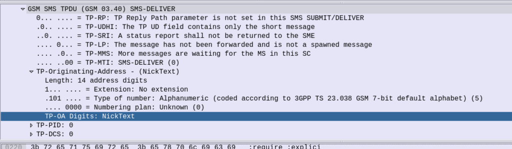
Well the TP-Originating address has the “Type of Number” (ToN) field which is typically set to International/National, but value 5 allows for the Digits to instead be alphanumeric characters.
GSM 7 bit encoding on the text in the TP-Originating Address digits and presto, you can send SMS to subscribers where the message shows as From an alphanumeric source.
On Android SMSs received from alphanumeric sources cannot be responded to (“no more “DO NOT REPLY TO THIS MESSAGE” at the end of each text), but on iOS devices you can respond, but if I send an SMS from “Nick” the reply from the subscriber using the iPhone will be sent to MSISDN 6425 (Nick on the telephone keypad).
Recently I’ve been doing some work with FreeSWITCH as an IMS Conference Factory, I’ve written a bit about it before in this post on using FreeSWITCH with the AMR codec.
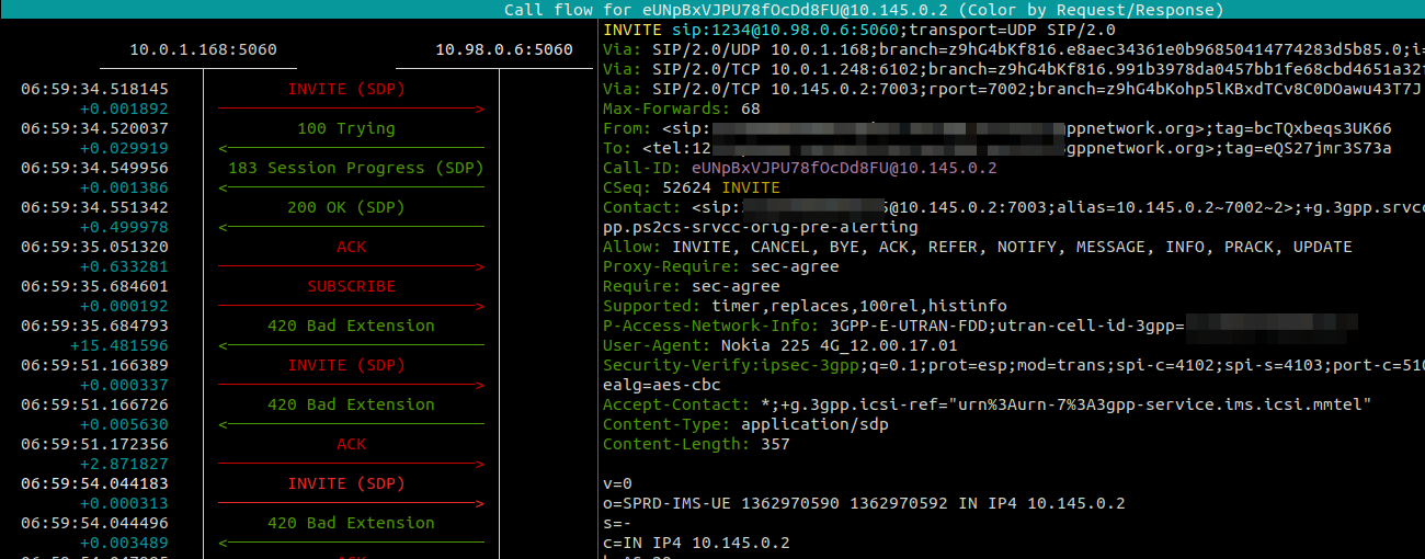
Pretty early on in my testing I faced a problem with subsequent in-dialog responses, like re-INVITEs used for holding the calls.
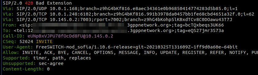
Every subsequent message, was getting a “420 Bad Extension” response from FreeSWITCH.
The ReINVITEThe 420 Bad Extension Response
So what didn’t it like and why was FreeSWITCH generating 420 Bad Extension Responses to these subsequent messages?
Well, the “Extensions” FreeSWITCH is referring to are not extensions in the Telephony sense – as in related to the Dialplan, like an Extension Number to identify a user, but rather the Extensions (as in expansions) to the SIP Protocol introduced for IMS.
The re-INVITE contains a Require header with sec-agree which is a SIP Extension introduced for IMS, which FreeSWITCH does not have support for, and the re-INVITE says is required to support the call (Not true in this case).
Using a Kamailio based S-CSCF means it is easy to strip these Headers before forwarding the requests onto the Application Server, which is what I’ve done, and bingo, no more errors!
In iOS 15, Apple added support for iPhones to support SMS over IMS networks – SMSoIP. Previously iPhone users have been relying on CSFB / SMSoNAS (Using the SGs interface) to send SMS on 4G networks.
Getting this working recently led me to some issues that took me longer than I’d like to admit to work out the root cause of…
I was finding that when sending a Mobile Termianted SMS to an iPhone as a SIP MESSAGE, the iPhone would send back the 200 OK to confirm delivery, but it never showed up on the screen to the user.
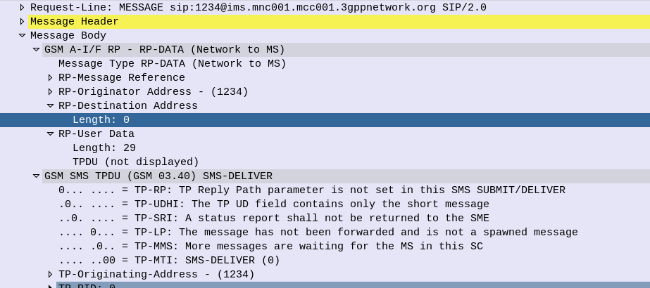
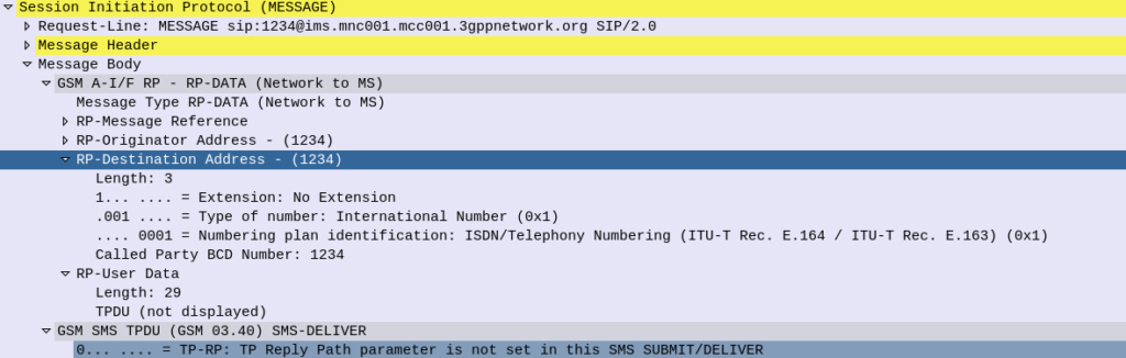
The GSM A-I/F headers in an SMS PDU are used primarily for indicating the sender of an SMS (Some carriers are configured to get this from the SIP From header, but the SMS PDU is most common).
The RP-Destination Address is used to indicate the destination for the SMS, and on all the models of handset I’ve been testing with, this is set to the MSISDN of the Subscriber.
But some devices are really finicky about it’s contents. Case in point, Apple iPhones.
If you send a Mobile Terminated SMS to an iPhone, like the one below, the iPhone will accept and send back a 200 OK to this request.
The problem is it will never be displayed to the user… The message is marked as delivered, the phone has accepted it it just hasn’t shown it…
SMS reports as delivered by the iPhone (200 OK back) but never gets displayed to the user of the phone as the RP-Destination Address header is populated
The fix is simple enough, if you set the RP-Destination Address header to 0, the message will be displayed to the user, but still took me a shamefully long time to work out the problem.
RP-Destination Address set to 0 sent to the iPhone, this time it’ll get displayed to the user.
After getting AMR support in FreeSWITCH I set about creating an IMS Application Server for VoLTE / IMS networks using FreeSWITCH.
So in IMS what is an Application Server? Well, the answer is almost anything that’s not a CSCF.
An Application Server could handle your Voicemail, recorded announcements, a Conference Factory, or help interconnect with other systems (without using a BGCF).
I’ll be using mine as a simple bridge between my SIP network and the IMS core I’ve got for VoLTE, with FreeSWITCH transcoding between AMR to PCMA.
Setting up FreeSWITCH
You’ll need to setup FreeSWITCH as per your needs, so that’s however you want to use it.
This post won’t cover setting up FreeSWITCH, there’s plenty of good resources out there for that.
The only difference is when you install FreeSWITCH, you will want to compile with AMR Support, so that you can interact with mobile phones using the AMR codec, which I’ve documented how to do here.
Setting up your IMS
In order to get calls from the IMS to the Application Server, we need a way of routing the calls to the Application Server.
There are two standards-compliant ways to achieve this,
But this is a blunt instrument, after all, it’ll only ever be used at the start of the call, what if we want to send it to an AS because a destination can’t be reached and we want to play back a recorded announcement?
To support Dedicated Bearers we first have to have a way of profiling the traffic, to classify the traffic as being the type we want to provide the Dedicated Bearer for.
The first step involves a request from an Application Function (AF) to the PCRF via the Rx interface.
The most common type of AF would be a P-CSCF. When a VoLTE call gets setup the P-CSCF requests that a dedicated bearer be setup for the IP Address and Ports involved in the VoLTE call, to ensure users get the best possible call quality.
But Application Functions aren’t limited to just VoLTE – You could also embed an Application Function into the server for an online game to enable a dedicated bearer for users playing that game, or a sports streaming app that detects when a user starts streaming sports and creates a dedicated bearer for that user to send the traffic down.
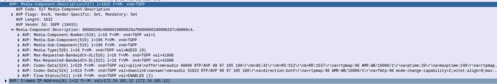
The request to setup a dedicated bearer comes in the form of a Diameter request message from the AF, using the Rx reference point, typically from the P-CSCF to the PCRF in the network in an “AA-Request”.
Of main interest in the AA-Request is the Media Component AVP, that contains all the details needed to identify the traffic flow.
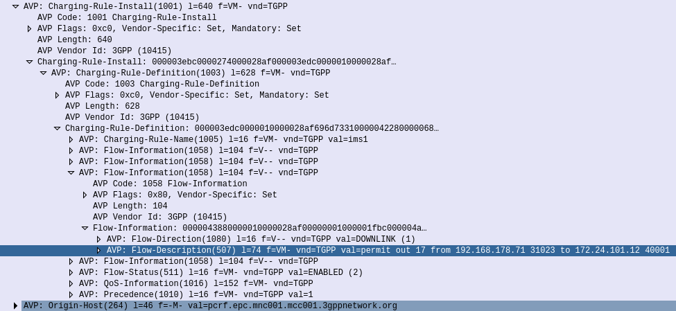
Now our PCRF is in charge of policy, and know which P-GW is serving the required subscriber. So the PCRF takes this information and sends a Gx Re-Auth Request to the PCEF in the P-GW serving the subscriber, with a Charging Rule the PCEF in the P-GW needs to install, to profile and apply QoS to the bearer.
Charging Rule Definition’s Flow-Information AVPs showing the information needed to profile the traffic
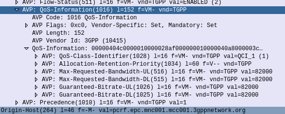
The QoS Description AVP defines which QoS parameters (QCI / ARP / Guaranteed & Maximum Bandwidth) should be applied to the traffic that matches the rules we just defined.
QoS Information AVP showing requested QoS Parameters
The P-GW sends back a Gx Re-Auth Answer, and gets to work actually setting up these bearers.
With the rule installed on the PCEF, it’s time to get this new bearer set up on the UE / eNodeB.
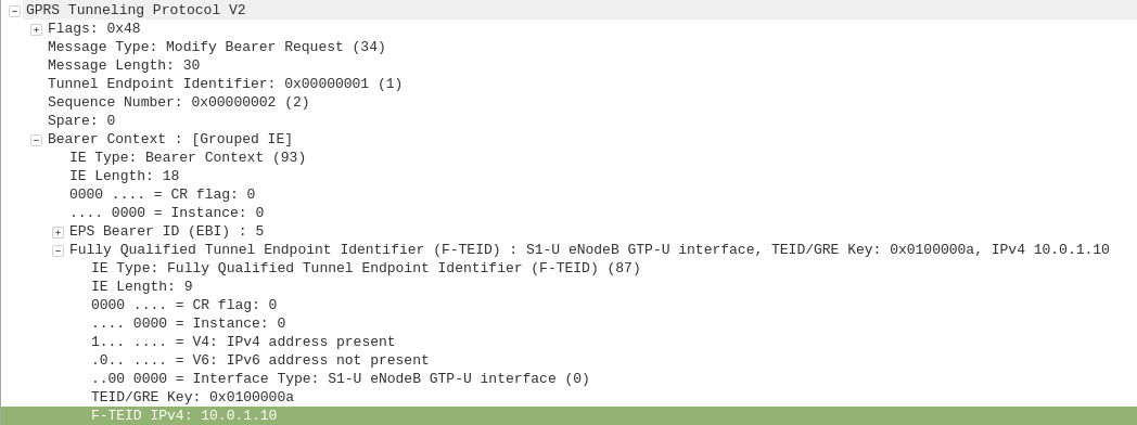
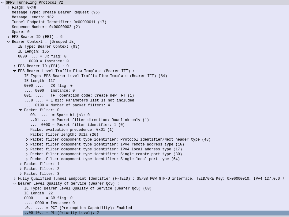
The P-GW sends a GTPv2 “Create Bearer Request” to the S-GW which forwards it onto the MME, to setup / define the Dedicated Bearer to be setup on the eNodeB.
GTPv2 “Create Bearer Request” sent by the P-Gw to the S-GW forwarded from the S-GW to the MME
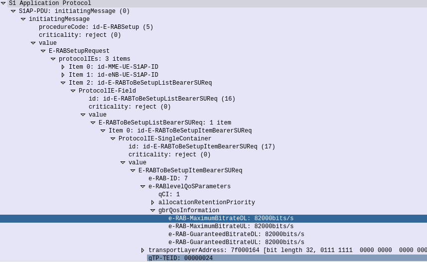
The MME translates this into an S1 “E-RAB Setup Request” which it sends to the eNodeB to setup,
S1 E-RAB Setup request showing the E-RAB to be setup
Assuming the eNodeB has the resources to setup this bearer, it provides the details to the UE and sets up the bearer, sending confirmation back to the MME in the S1 “E-RAB Setup Response” message, which the MME translates back into GTPv2 for a “Create Bearer Response”
All this effort to keep your VoLTE calls sounding great!
Early on as subscriber trunk dialing and automated time-based charging was introduced to phone networks, engineers were faced with a problem from Payphones.
Previously a call had been a fixed price, once the caller put in their coins, if they put in enough coins, they could dial and stay on the line as long as they wanted.
But as the length of calls began to be metered, it means if I put $3 of coins into the payphone, and make a call to a destination that costs $1 per minute, then I should only be allowed to have a 3 minute long phone call, and the call should be cutoff before the 4th minute, as I would have used all my available credit.
Conversely if I put $3 into the Payphone and only call a $1 per minute destination for 2 minutes, I should get $1 refunded at the end of my call.
We see the exact same problem with prepaid subscribers on IMS Networks, and it’s solved in much the same way.
In LTE/EPC Networks, Diameter is used for all our credit control, with all online charging based on the Ro interface. So let’s take a look at how this works and what goes on.
Generic 3GPP Online Charging Architecture
3GPP defines a generic 3GPP Online charging architecture, that’s used by IMS for Credit Control of prepaid subscribers, but also for prepaid metering of data usage, other volume based flows, as well as event-based charging like SMS and MMS.
Network functions that handle chargeable services (like the data transferred through a P-GW or calls through a S-CSCF) contain a Charging Trigger Function (CTF) (While reading the specifications, you may be left thinking that the Charging Trigger Function is a separate entity, but more often than not, the CTF is built into the network element as an interface).
The CTF is a Diameter application that generates requests to the Online Charging Function (OCF) to be granted resources for the session / call / data flow, the subscriber wants to use, prior to granting them the service.
So network elements that need to charge for services in realtime contain a Charging Trigger Function (CTF) which in turn talks to an Online Charging Function (OCF) which typically is part of an Online Charging System (AKA OCS).
For example when a subscriber turns on their phone and a GTP session is setup on the P-GW/PCEF, but before data is allowed to flow through it, a Diameter “Credit Control Request” is generated by the Charging Trigger Function (CTF) in the P-GW/PCEF, which is sent to our Online Charging Server (OCS).
The “Credit Control Answer” back from the OCS indicates the subscriber has the balance needed to use data services, and specifies how much data up and down the subscriber has been granted to use.
The P-GW/PCEF grants service to the subscriber for the specified amount of units, and the subscriber can start using data.
This is a simplified example – Decentralized vs Centralized Rating and Unit Determination enter into this, session reservation, etc.
The interface between our Charging Trigger Functions (CTF) and the Online Charging Functions (OCF), is the Ro interface, which is a Diameter based interface, and is common not just for online charging for data usage, IMS Credit Control, MMS, value added services, etc.
3GPP define a reference online-charging interface, the Ro interface, and all the application-specific interfaces, like the Gy for billing data usage, build on top of the Ro interface spec.
Basic Credit Control Request / Credit Control Answer Process
This example will look at a VoLTE call over IMS.
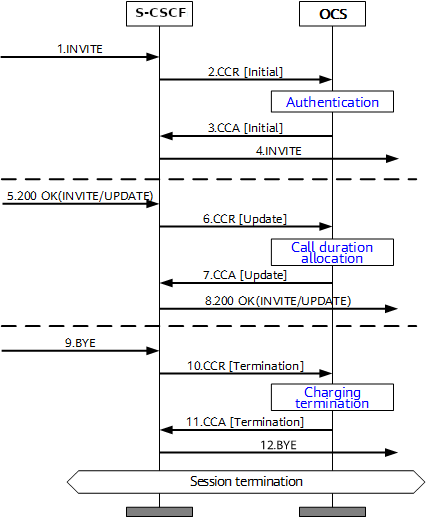
When a subscriber sends an INVITE, the Charging Trigger Function baked in our S-CSCF sends a Diameter “Credit Control Request” (CCR) to our Online Charging Function, with the type INITIAL, meaning this is the first CCR for this session.
The CCR contains the Service Information AVP. It’s this little AVP that is where the majority of the magic happens, as it defines what the service the subscriber is requesting. The main difference between the multitude of online charging interfaces in EPC networks, is just what the service the customer is requesting, and the specifics of that service.
For this example it’s a voice call, so this Service Information AVP contains a “IMS-Information” AVP. This AVP defines all the parameters for a IMS phone call to be online charged, for a voice call, this is the called-party, calling party, SDP (for differentiating between voice / video, etc.).
It’s the contents of this Service Information AVP the OCS uses to make decision on if service should be granted or not, and how many service units to be granted. (If Centralized Rating and Unit Determination is used, we’ll cover that in another post) The actual logic, relating to this decision is typically based on the the rating and tariffing, credit control profiles, etc, and is outside the scope of the interface, but in short, the OCS will make a yes/no decision about if the subscriber should be granted access to the particular service, and if yes, then how many minutes / Bytes / Events should be granted.
In the received Credit Control Answer is received back from our OCS, and the Granted-Service-Unit AVP is analysed by the S-CSCF. For a voice call, the service units will be time. This tells the S-CSCF how long the call can go on before the S-CSCF will need to send another Credit Control Request, for the purposes of this example we’ll imagine the returned value is 600 seconds / 10 minutes.
The S-CSCF will then grant service, the subscriber can start their voice call, and start the countdown of the time granted by the OCS.
As our chatty subscriber stays on their call, the S-CSCF approaches the limit of the Granted Service units from the OCS (Say 500 seconds used of the 600 seconds granted). Before this limit is reached the S-CSCF’s CTF function sends another Credit Control Request with the type UPDATE_REQUEST. This allows the OCS to analyse the remaining balance of the subscriber and policies to tell the S-CSCF how long the call can continue to proceed for in the form of granted service units returned in the Credit Control Answer, which for our example can be 300 seconds.
Eventually, and before the second lot of granted units runs out, our subscriber ends the call, for a total talk time of 700 seconds.
But wait, the subscriber been granted 600 seconds for our INITIAL request, and a further 300 seconds in our UPDATE_REQUEST, for a total of 900 seconds, but the subscriber only used 700 seconds?
The S-CSCF sends a final Credit Control Request, this time with type TERMINATION_REQUEST and lets the OCS know via the Used-Service-Unit AVP, how many units the subscriber actually used (700 seconds), meaning the OCS will refund the balance for the gap of 200 seconds the subscriber didn’t use.
If this were the interface for online charging of data, we’d have the PS-Information AVP, or for online charging of SMS we’d have the SMS-Information, and so on.
The architecture and framework for how the charging works doesn’t change between a voice call, data traffic or messaging, just the particulars for the type of service we need to bill, as defined in the Service Information AVP, and the OCS making a decision on that based on if the subscriber should be granted service, and if yes, how many units of whatever type.
In the last we covered what ENUM is and how it works, so to take this into a more practical example, I thought I’d share the details of the ENUM server I’ve setup in my lab, and the Docker container I’ve bundled it into.
Inside the Docker container we’ll be running Bind – this post won’t teach you much about Bind, there’s already lots of good information on it elsewhere, but we will cover the parameters involved in setting up ENUM records (NAPTR) for E.164 addresses.
Getting the Environment up and Running
First we’ll need to setup our environment, I’ve published the images for the container to Dockerhub, but we’ll build it from the Dockerfile so you can edit the files and rebuild as you play around:
systemd-resolve on Ubuntu binds to port 53 by default, which can lead to some headaches, so we’ll create a new network in Docker for this to run in, so it doesn’t conflict with anything else you may be running:
And now we’ll run the ENUM container in the enum_playground network and with the IP 172.30.0.2,
docker run -d --rm --name=enum --net=enum_playground --ip=172.30.0.2 enum
Ok, that’s the environment setup, let’s run some queries!
E.164 to SIP URI Resolution with ENUM
In our last post we covered the basics of formatting an E.164 number and querying a DNS server to get it’s call routing information.
Again we’re going to use Dig to query this information. In reality ENUM queries would be run by an endpoint, or software like FreeSWITCH or Kamailio (Spoiler alert, posts on ENUM handling in those coming later), but as we’re just playing Dig will work fine.
So let’s start by querying a single E.164 address, +61355500911
First we’ll reverse it and put full stops / periods between the numbers, to get 1.1.9.0.0.5.5.5.3.1.6
Next we’ll add the e164.arpa prefix, which is the global prefix for ENUM addresses, and presto, that’s what we’ll query – 1.1.9.0.0.5.5.5.3.1.6.e164.arpa
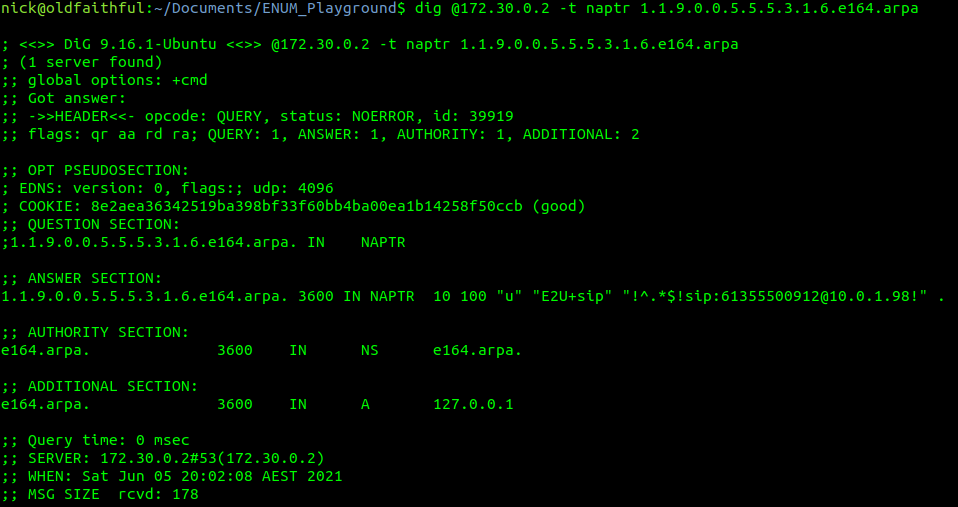
Lastly we’ll feed this into a Dig query against the IP of our container and of type NAPTR,
Next up is the TTL or expiry, in this case it’s 3600 seconds (1 hour), shorter periods allow for changes to propagate / be reflected more quickly but at the expense of more load as results can’t be cached for as long. The class (IN) represents Internet, which is the only class commonly used, even on internal systems.
Then we have the type of record returned, in our case it’s a NAPTR record,
1.1.9.0.0.5.5.5.3.1.6.e164.arpa.3600 IN NAPTR 10 100 "u" "E2U+sip" "!^.*$!sip:[email protected]!" .
After that is the Order, this defines the order in which the rules are to be parsed. Lower numbers are processed first, if no matches then the next lowest, and so on until the highest number is reached, we’ll touch on this in more detail later in this post,
1.1.9.0.0.5.5.5.3.1.6.e164.arpa.3600 IN NAPTR 10 100 "u" "E2U+sip" "!^.*$!sip:[email protected]!" .
The Pref is the processing preference. This is very handy for load balancing, as we can split traffic between hosts with different preferences. We’ll cover this later in this post too.
1.1.9.0.0.5.5.5.3.1.6.e164.arpa.3600 IN NAPTR 10 100 "u" "E2U+sip" "!^.*$!sip:[email protected]!" .
The Flags represent the type of record we’re going to get, for most ENUM traffic this is going to be set to U, to denote a SIP URI with Regex, while the Service value we’ll be looking for will be “E2U+sip” service to identify SIP URIs to route calls to, but could be other values like Email addresses, IM Addresses or PSTN numbers, to be parsed by other applications.
1.1.9.0.0.5.5.5.3.1.6.e164.arpa.3600 IN NAPTR 10 100 "u" "E2U+sip" "!^.*$!sip:[email protected]!" .
Lastly we’ve got the Regex part. Again not going to cover Regex as a whole, just the DNS particulars.
Everything between the first and second ! denotes what we’re searching for, while everything from the second ! to the last ! denotes what we replace it with.
In the below example that means we’re matching ^.* which means starting with (^) any character (.) zero or more times (*), which gets replaced with sip:[email protected],
1.1.9.0.0.5.5.5.3.1.6.e164.arpa.3600 IN NAPTR 10 100"u" "E2U+sip" "!^.*$!sip:[email protected]!" .
How should this be treated?
For the first example, a call to the E.164 address of 61355500912 will be first formatted into a domain as per the ENUM requirements (1.1.9.0.0.5.5.5.3.1.6.e164.arpa) and then queried as a NAPTR record against the DNS server,
1.1.9.0.0.5.5.5.3.1.6.e164.arpa.3600 IN NAPTR 10 100"u" "E2U+sip" "!^.*$!sip:[email protected]!" .
Only a single record has been returned so we don’t need to worry about the Order or Preference, and the Regex matches anything and replaces it with the resulting SIP URI of sip:[email protected], which is where we’ll send our INVITE.
Under the Hood
Inside the Repo we cloned earlier, if you open the e164.arpa.db file, things will look somewhat familiar,
The record we just queried is the first example in the Bind config file,
; E.164 Address +61355500911 - Simple no replacement (Resolves all traffic to sip:[email protected])
1.1.9.0.0.5.5.5.3.1.6 IN NAPTR 10 100 "u" "E2U+sip" "!^.*$!sip:[email protected]!" .
The config file is just the domain, class, type, order, preference, flags, service and regex.
Astute readers may have noticed the trailing . which where we can put a replacement domain if Regex is not used, but it cannot be used in conjunction with Regex, so for all our work it’ll just be a single trailing . on each line.
You can (and probably should) change the values in the e164.arpa.db file as we go along to try everything out, you’ll just need to rebuild the container and restart it each time you make a change.
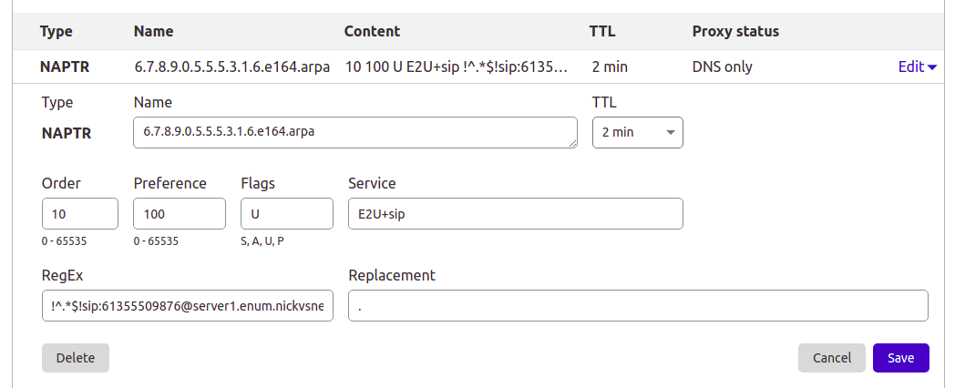
This post is going to focus on Bind, but the majority of modern DNS servers support NAPTR records, so you can use them for ENUM as well, for example I manage the DNS for this site thorough Cloudflare, and I’ve put a screenshot below of an example private ENUM address I’ve added into it.
Setting up a NAPTR record in Cloudflare DNS
Preference to Split Traffic between Servers
So with a firm understanding of a single record being returned, let’s look at how we can use ENUM to cleverly route traffic to multiple hosts.
If we have a pool of servers we may wish to evenly distribute all traffic across them, so that’s how E.164 address +61355500912 is setup – to route traffic evenly (50/50) across two servers.
Querying it with Dig provides the following result:
So as the order value (10) is the same for both records, we can ignore it – there isn’t one value lower than the other.
We can see both records have a preference of 100, in practice, this means they each get 50% of the traffic. The formula for traffic distribution is pretty simple, each server gets the value of it’s preference, divided by the total of all the preferences,
So for server1 it’s preference is 100 and the total of all the preferences combined is 200, so it gets 100/200, which is equivalent to one half aka 50%.
We might have a scenario where we have 3 servers, but one is significantly more powerful than the others, so let’s look at giving more traffic to one server and less to others, this example gets a little more complex but should cement your understanding of how the preference works;
So now 3 servers, again none have a lower order than the other, it’s set to 10 for them all so we can ignore the order,
Next we can see the total of all the priority values is 400,
Server 2 has a priority of 100 so it gets 100/400 total priority, or a quarter of all traffic. Server 1 has the same value, so also gets a quarter of all traffic,
Server 3 however has a priority of 200 so it gets 200/400, or to simplify half of all traffic.
The Bind config for this is:
; E.164 Address +61355500913 - More complex load balance between 3 hosts (25% server1, 25% server2, 50% server3)
3.1.9.0.0.5.5.5.3.1.6 IN NAPTR 10 100 "u" "E2U+sip" "!^.*$!sip:[email protected]!" . 3.1.9.0.0.5.5.5.3.1.6 IN NAPTR 10 100 "u" "E2U+sip" "!^.*$!sip:[email protected]!" .
3.1.9.0.0.5.5.5.3.1.6 IN NAPTR 10 200 "u" "E2U+sip" "!^.*$!sip:[email protected]!" .
Order for Failover
Primarily the purpose of the order is to enable wildcard routes (as we’ll see later) to be overwritten by more specific routes, but a secondary use in some implementations use Order as a way to list the preferences of the SIP URIs to route to. For example we could have two servers, one a primary and the other a standby, with the standby only to be used only if the primary SIP URI was not responding.
E.164 number +61355500914 is setup to return two SIP URIs,
Our DNS client will first use the SIP URI sip:[email protected] as it has the lower order value (10), and if that fails, can try the entry with the next lowest order-value (20) which would be sip:[email protected].
The Bind config for this is:
; E.164 Address +61355500914 - Order example returning multiple SIP URIs to try for failover
4.1.9.0.0.5.5.5.3.1.6 IN NAPTR 10 100 "u" "E2U+sip" "!^.*$!sip:[email protected]!" . 4.1.9.0.0.5.5.5.3.1.6 IN NAPTR 20 100 "u" "E2U+sip" "!^.*$!sip:[email protected]!" .
Wildcards
If we have a 1,000 number block, having to add 1000 individual records can be very tedious. Instead we can use wildcard matching (thanks to the fact we’ve reversed the E.164 address) to match ranges. For example if we have E.164 numbers from +61255501000 to +61255501999 we can add a wildcard entry to match the +61255501x prefix,
I’ve set this up already so let’s lookup the E.164 number +6125501234,
If you look up any other number starting with +6125501 you’ll get the same result, and here’s the Bind config for it:
; Wildcard E.164 Address +61255501* - Wildcard example for all destinations starting with E.164 prefix +61255501x to single destination (sip:[email protected])
; For example E.164 number +6125501234 will resolve to sip:[email protected]
*.1.0.5.5.5.2.1.6 IN NAPTR 100 100 "u" "E2U+sip" "!^.*$!sip:[email protected]!" .
The catch with this is they’re all pointing at the same SIP URI, so we can’t treat the calls differently based on the called number – This is where the Regex magic comes in.
We can use group matching to match a group and fill it in the dialed number into the SIP Request URI, for example:
Will match the E.164 number requested and put it inside sip:[email protected]
The +61255502xxx prefix is setup for this, so if we query +61255502000 (or any other number between +61255502000 and +61255502999) we’ll get the regex query in the resulting record.
Keep in mind DNS doesn’t actually apply the Regex transformation, just shares it, and the client applies the transformation.
; Wildcard example for all destinations starting with E.164 prefix +61255502x to regex filled destination
; For example a request to 61255502000 will return sip:[email protected])
*.2.0.5.5.5.2.1.6 IN NAPTR 100 100 "u" "E2U+sip" "!(^.*$)!sip:+1\\[email protected]!" .
One last thing to keep in mind, is that Wildcard priorities are of any length. This means +612555021 would match as well as +6125550299999999999999. Typically terminating switches drop any superfluous digits, and NU those that are too short, but keep this in mind, that length is not taken into account.
Wildcard Priorities
So with our wildcards in place, what if we wanted to add an exception, for example one number in our 61255502xxx block of numbers gets ported to another carrier and needs to be routed elsewhere?
Easy, we just add another entry for that number being more specific and with a lower order than the wildcard, which is what’s setup for E.164 number +61255502345,
Which does not return the same result as the others that match the wildcard,
Bind config:
; Wildcard example for all destinations starting with E.164 prefix +61255502x to regex filled destination
; For example a request to +61255502000 will return sip:[email protected])
*.2.0.5.5.5.2.1.6 IN NAPTR 100 100 "u" "E2U+sip" "!(^.*$)!sip:+1\\[email protected]!" .

; More specific example with lower order than +6125550x wildcard for E.164 address +61255502345 will return sip:[email protected]
5.4.3.2.0.5.5.5.2.1.6 IN NAPTR 50 100 "u" "E2U+sip" "!^.*$!sip:[email protected]!" .
We can combine all of the tricks we’ve covered here, from statically defined entries, wildcards, regex replacement, multiple entries with multiple orders and preferences, to create really complex routing, using only DNS.
Summary & Next Steps
So by now hopefully you’ve got a fair understanding of how NAPTR and DNS work together to translate E.164 addresses into SIP URIs,
Of course being able to do this manually with Dig and comprehend how it’ll route is only one part of the picture, in the next posts we’ll cover using Kamailio and FreeSWITCH to query ENUM routing information and route traffic to it,
SIP routing is complicated, there’s edge cases, traffic that can be switched locally and other traffic that needs to be proxied off to another Proxy or Application server. How can you define these rules and logic in a flexible way, that allows these rules to be distributed out to multiple different network elements and adjusted on a per-subscriber basis?
Enter iFCs – The Initial Filter Criteria.
iFCs are XML encoded rules to define which servers should handle traffic matching a set of rules.
Let’s look at some example rules we might want to handle through iFCs:
Send all SIP NOTIFY, SUBSCRIBE and PUBLISH requests to a presence server
Any Mobile Originated SMS to an SMSc
Calls to a specific destination to a MGC
Route any SIP INVITE requests with video codecs present to a VC bridge
Send calls to Subscribers who aren’t registered to a Voicemail server
Use 3rd party registration to alert a server that a Subscriber has registered
All of these can be defined and executed through iFCs, so let’s take a look,
iFC Structure
iFCs are encoded in XML and typically contained in the Cx-user-data AVP presented in a Cx Server Assignment Answer response.
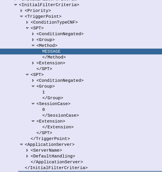
Let’s take a look at an example iFC and then break down the details as to what we’re specifying.
Each rule in an iFC is made up of a Priority, TriggerPoint and ApplicationServer.
So for starters we’ll look at the Priority tag. The Priority tag allows us to have multiple-tiers of priority and multiple levels of matching, For example if we had traffic matching the conditions outlined in this rule (TriggerPoint) but also matching another rule with a lower priority, the lower priority rule would take precedence.
Inside our <TriggerPoint> tag contains the specifics of the rules and how the rules will be joined / matched, which is what we’ll focus on predominantly, and is followed by the <ApplicationServer> which is where we will route the traffic to if the TriggerPoint is matched / triggered.
So let’s look a bit more about what’s going on inside the TriggerPoint.
Each TriggerPoint is made up of Service Point Trigger (SPTs) which are individual rules that are matched or not matched, that are either combined as logical AND or logical OR statements when evaluated.
By using fairly simple building blocks of SPTs we can create a complex set of rules by joining them together.
Service Point Triggers (SPTs)
Let’s take a closer look at what goes on in an SPT. Below is a simple SPT that will match all SIP requests using the SIP MESSAGE method request type:
So as you may have guessed, the <Method> tag inside the SPT defines what SIP request method we’re going to match.
But Method is only one example of the matching mechanism we can use, but we can also match on other attributes, such as Request URI, SIP Header, Session Case (Mobile Originated vs Mobile Terminated) and Session Description such as SDP.
Or an example of a SPT for anything Originating from the Subscriber utilizing the <SessionCase> tag inside the SPT.
Having <Header> will match if the header is present, while the optional Content tag can be used to match
In terms of the Content this is matched using Regular Expressions, but in this case, not so regular regular expressions. 3GPP selected Extended Regular Expressions (ERE) to be used (IEEE POSIX) which are similar to the de facto standard PCRE Regex, but with a few fewer parameters.
Condition Negated
The <ConditionNegated> tag inside the SPT allows us to do an inverse match.
In short it will match anything other than what is specified in the SPT.
For example if we wanted to match any SIP Methods other than MESSAGE, setting <ConditionNegated>1</ConditionNegated> would do just that, as shown below:
Finally the <Group> tag allows us to group together a group of rules for the purpose of evaluating. We’ll go into it more in in the below section.
ConditionTypeCNF / ConditionTypeDNF
As we touched on earlier, <TriggerPoints> contain all the SPTs, but also, very importantly, specify how they will be interpreted.
SPTs can be joined in AND or OR conditions.
For some scenarios we may want to match where METHOD is MESSAGE and RequestURI is sip:[email protected], which is different to matching where the METHOD is MESSAGE or RequestURI is sip:[email protected].
This behaviour is set by the presence of one of the ConditionTypeCNF (Conjunctive Normal Form) or ConditionTypeDNF (Disjunctive Normal Form) tags.
If each SPT has a unique number in the GroupTag and ConditionTypeCNF is set then we evaluate as AND.
If each SPT has a unique number in the GroupTag and ConditionTypeDNF is set then we evaluate as OR.
Let’s look at how the below rule is evaluated as AND as ConditionTypeCNF is set:
This means we will match if the method is MESSAGE and Session Case is 0 (Mobile Originated) as each SPT is in a different Group which leads to “and” behaviour.
If we were to flip to ConditionTypeDNF each of the SPTs are evaluated as OR.
If you’re building IMS Networks, the AMR config is a must, but FreeSWITCH does not ship with AMR due to licencing constraints, but has all the hard work done, you just need to add the headers for AMR support and compile.
LibOpenCore has support for AMR which we build, and then with a few minor tweaks to copy the C++ header files over to the FreeSWITCH source directory, and enable support in modules.conf.
Then when building FreeSWITCH you’ve got the AMR Codec to enable you to manage IMS / VoLTE media streams from mobile devices.
Instead of copying and pasting a list of commands to do this, I’ve published a Dockerfile here you can use to build a Docker image, or on a straight Debian Buster machine if you’re working on VMs or Bare Metal if you run the commands from the Dockerfile on the VM / bare metal.