LTE has great concepts like NAS that abstract the actual transport layers, so the NAS packet is generated by the UE and then read by the MME.
One thing that’s a real headache about private LTE is the authentication side of things. You’ll probably bash your head against a SIM programmer for some time.
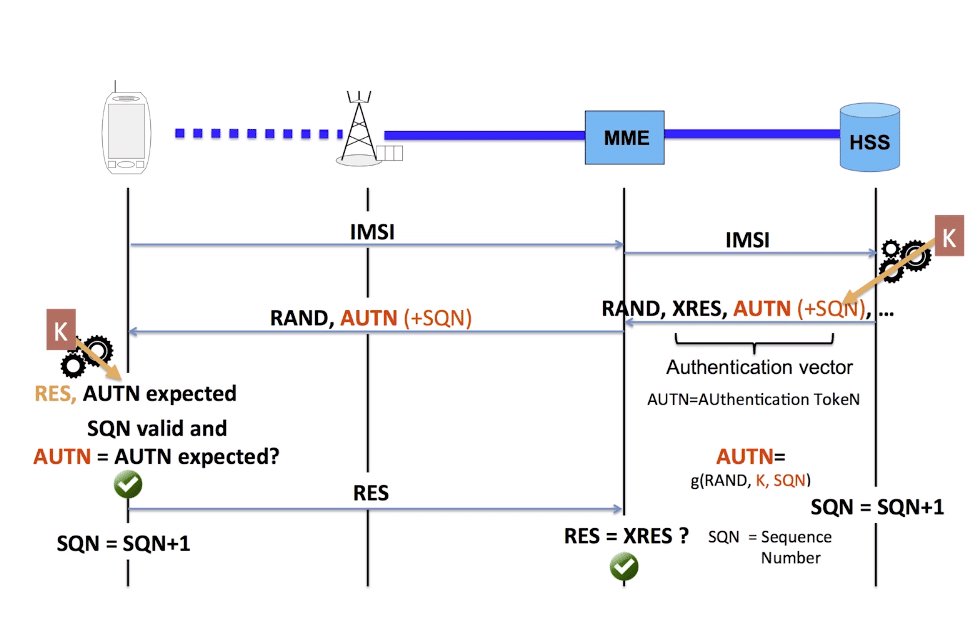
As your probably know when connecting to a network, the UE shares it’s IMSI / TIMSI with the network, and the MME requests authentication information from the HSS using the Authentication Information Request over Diameter.
The HSS then returns a random value (RAND), expected result (XRES), authentication token (AUTN) and a KASME for generating further keys,
The RAND and AUTN values are sent to the UE, the USIM in the UE calculates the RES (result) and sends it back to the MME. If the RES value received by the MME is equal to the expected RES (XRES) then the subscriber is mutually authenticated.
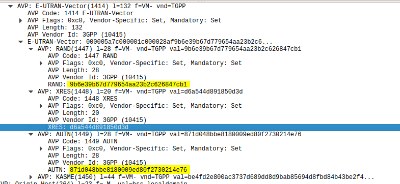
Using this tool I was able to plug a USIM into my USIM reader, using the Diameter client built into PyHSS I was able to ask for Authentication vectors for a UE using the Authentication Information Request to the HSS and was sent back the Authentication Information Answer containing the RAND and AUTN values, as well as the XRES value.
Diameter – Authentication Information Response showing E-UTRAN Vectors
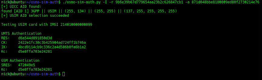
Then I used the osmo-sim-auth app to query the RES and RAND values against the USIM.
The RES I got back matched the XRES, meaning the HSS and the USIM are in sync (SQNs match) and they mutually authenticated.
Let’s take a look at GTP, the workhorse of mobile user plane packet data.
This post covers all generations of mobile data (2.5 -> 5G), so I’m using generic terms.
GSM, UMTS, LTE & NR all have one protocol in common – GTP – The GPRS Tunneling Protocol.
So why do every generation of mobile data networks from GSM/GPRS in 2000, to 5G NR Standalone in 2020, rely on this one protocol for transporting user data?
So Why GTP?
GTP – the GPRS Tunnelling Protocol, is what encapsulates and tunnels IP packets from the internet / packet data network, to and from the User.
So why encapsulate the packets? What if the Base Station had access to the internet and routed the traffic to the users?
Let’s say we did that, we’d have to have large pools of IP addresses available at each Base Station and when a user connected they’d be assigned an IP Address and traffic for these users would be routed to the Base Station which would forward it onto the user.
This would work well until a user moves from one Base Station to another, when they’d have to get a new IP Address allocated.
TCP/IP was never designed to be mobile, an IP address only exists in a single location.
Breaking out traffic directly from a base station would have other issues, such as no easy way to enforce QoS or traffic policies, meter usage, etc.
How to fix IP’s lack of mobility? GTP.
GTP addressed the mobility issue by having a single fixed point the IP Address is assigned to (In GSM/GRPS/UMTS this is the Gateway GPRS Support Node, in LTE this is the P-GW and in 5G-SA this is the UPF), which encapsulates IP traffic to/from a mobile user into GTP Packet.
You can think of GTP like GRE or any of the other common encapsulation protocols, wrapping up the IP packets into a GTP packet which we can rerouted to different Base Stations as the users move from being served by one Base Station to another.
This easy redirecting / rerouting of user traffic is why GTP is used for NR (5G), LTE (4G), UMTS (3G) & GPRS (2.5G) architectures.
GTP Packets
When looking at a GTP packet of user data you’d be forgiven for thinking nothing much goes on,
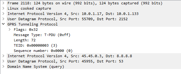
Example GTP packet containing a DNS query
Like in most tunneling / encapsulation protocols we’ve got the original network / protocol stack of IPv4 and UDP, and a payload of a GTP packet.
The packet itself is pretty bare bones, there’s flags, denoting a few basics like version number, the message type (T-PDU), the length of the GTP packet and it’s payload (used for delineating the end of the payload), a sequence number an a Tunnel Endpoint Identifier (TEID).
In the payload, we can see the network / protocol stack and application layer of the contents of the GTP packet.
From a mobility standpoint, the beauty of GTP is that it takes IP packets and puts them into a media stream of sorts, with out of band signalling, this means we can change the parameters of our GTP stream easily without touching the encapsulated IP Packet.
When a UE moves from one base station to another, all that has to happen is the destination the GTP packets are sent to is changed from the old base station to the new base station. This is signalled using GTP-C in GPRS/UMTS, GTPv2-C in LTE and HTTP in 5G-SA.
Traffic to and from the UE would look the same as the screenshot above, the only difference would be the first IPv4 address would be different, but the IPv4 address in the GTP tunnel would be the same.
Why am I still billed after a number is ported out?
The Losing CSP does not need to take any action to disconnect Customer’s Telephone Number(s).
3.4.3
This means just porting out a number from a CSP doesn’t mean billing from the Loosing CSP will stop.
Continuing contractual agreements between the customer and Loosing CSP may still be in place and the customer is responsible for requesting the services be cancelled with the Loosing CSP.
Some CSPs work out that if you’re porting out a number you don’t want their services anymore, but they’re not obliged to and most will do what they can get away with.
What is a Bilateral Peering Agreement?
While a customer is legally entitled to move a number they have full control over (As outlined in Telecommunications Numbering Plan 2015), in practice phone numbers can only be moved from one carrier to another if both CSPs have a Bilateral Peering Agreement with each other.
These agreements primarily sort out the commercials of how much they’ll pay each other per port in / out.
It’s worth also noting that the Code only defines the minimum standard and process, two CSPs that have a bilateral peering agreement in place are able to process ports faster and more efficiently than the minimum standard outlined in the code.
Carriage Service Provider vs Carrier?
I’ve been sing the term Carriage Service Provider and Carrier interchangeably.
The difference as far as the code is concerned is one is who a customer pays for the service, while the other is the provider of the service. Generally it’s safe to assume that the CSP is also the Carrier and not a re-seller.
These numbers can be ported to other CSPs (this is after all what LNP is all about) but after the number is routed to a different carrier the Donor Carrier remains the carrier listed in the Numbering Plan.
The Donor Carrier is responsible for Donor Transit Routing (A temporary redirect to numbers that have been ported away recently) for any numbers that have recently been ported out, and publishing the number and new carrier details for each number ported out in their PLNR file.
These numbers can be ported to other CSPs (this is after all what LNP is all about) but after the number is routed to a different carrier the Donor Carrier remains the carrier listed in the Numbering Plan.
In a scenario where a call needs to route to a destination where the current carrier for that destination is unknown, the call is routed to the Donor Carrier, as that’s who the number is originally allocated to by ACMA.
Upon reciept of a call by the donor carrier to a number that has been ported out, the donor’s switch finds the correct Access Service Deliver (ASD) and redirects the call to them.
This is a temporary service – CSPs are only obliged to do this for 5 days, after which it’s assumed the PLNR file of the donor will have been read by all the other CSPs and they’ll be routing the traffic to the correct CSP and not the Donor CSP.
Third Party Ports
Third Party Porting is where the Donor Carrier is neither the Losing Carrier or the Gaining Carrier. Third Party Porting requires bilateral agreements to be in place between each of the parties involved.
As we just covered ACMA allocates numbers to CSPs, when a number is ported to a different CSP the number is still allocated to the original CSP as far as ACMA and The Numbering System are concerned.
The CSP the number was originally allocated to is the Donor CSP – forever.
Let’s look at a two party port first:
A number is allocated by ACMA to CSP 1
The customer using that number decides to port the to CSP 2 using the standard LNP process
CSP 1 performs Donor Transit Routing for the required 5 days and updates it’s PLNR file to denote that the number has been ported to CSP 2
Now let’s consider a three party port, carrying on from the steps above.
The Customer decides they want to move from CSP 2 to another CSP – CSP 3
At the time of the port the donor CSP (CSP 1) must:
CSP 1 must update it’s PLNR records for this number to denote it’s no longer with CSP 2 but is now with CSP 3
CSP 1 must provide Donor Transit Routing for the required 5 business days – redirecting calls to CSP 3
So even though the number is moving from CSP 2 to CSP 3 as the number was originally allocated to CSP 1, it is, and will always be the Donor Carrier and as such has to provide Donor Transit Routing and update it’s PLNR each time the number is ported.
Port Reversal / Emergency Return
Ports have an emergency return window inside which the port can be reverted. For Cat C ports this invovles the project manager of one CSP contacting the project manager for the other CSP and requesting the return.
In the event the end customer has requested the Port Reversal / Emergency return they’re typically liable for a very hefty fee to do so.
Give Back & Quarantine of Numbers
After a number is no longer required, it’s given back to the donor carrier who places it in quarantine and typically does not reallocate the number for 6 months.
In some cases such as a wronly cancelled number the customer may be able to get a number that’s been cancelled back while it’s in it’s quarantine state, however this is not required and up to the donor carrier.
Including Customer Account Numbers when Porting
Prior to 2016, a customer moving from one CSP to another CSP were required to include their account number (“Service Account Number”) they had with the Loosing CSP to the Gaining CSP when submitting the Port which was verified against the Loosing Carrier’s records to ensure the correct Customer / Service combo.
This led to a lot of ports being rejected unnecessarily due to mismatched account numbers, as such the the requirement to include a valid matching account number with the loosing CSP has been removed.
Service Account is to remain as a mandatory field, and a standard validation but any mismatches are not to be rejected.
Where’s Cat B & Cat D?
Cat B Dropped in 2013 revision due to lack of use.
Cat D is almost the same as a Cat A port but allows services with an active ULL diversion to be ported. These are quite rare and a very specific use case.
Why is my Cat C Port taking so long?
You may find after submitting a port the date you’ve got back for porting is months away. The Loosing Carrier sets the porting date, and as they’re loosing the customer, they’re often not so keen to action the port quickly when they’re loosing the customer after all.
Lead Times are determined by the Losing Carrier. These may vary by product including variations due to the size of the product or the number of sites to which a particular service is offered.
3.5.10
Tidbit: One of Australia’s largest carriers has a 20,000 number per day limit on porting, meaning they’re only able to process up to 20,000 ports per day in or out. Once that limit is reached no more ports can be accepted for that day, so the ports are delayed until the next day, etc, etc, leading to considerable lead times.
The code requires CSPs to keep Service Metrics on porting time-frames, but there’s no penalty for being slow. (Section 3.6)
Third Party ports also take a lot longer due to the requirement to find a time window that suits all 3 carriers.
Can I arrange my numbers to be Ported after-hours?
CSPs are not required to port numbers outside of the “Standard Hours” defined in the code. (Section 3.8.1 )
However, most CSPs have included support for this inside their bilateral agreements with other carriers. This typically costs more for the customer, but also comes with the added risk of if the port fails there are fewer technical / engineering resources available at the Loosing and Gaining Carrier’s respective ends to sort it out if something goes wrong.
What’s a PNO?
Porting Notification Order – A message containing either a Simple Notification Advise (SNO) for Simple (Cat A) ports, or a Complex Notification Advise (CNA) for Complex (Cat C) ports.
Each PNO contains a unique sequential reference number to differentiate / associate the PNO with a particular porting request.
PLNR – Ported Local Number Registry
PLNR is nothing more than a giant text file, containing a list of numbers originally allocated to that CSP but that have been ported to another CSP, and with each number that’s been ported out the carrier code of the CSP it’s now with.
Information to facilitate Call Routing is provided by the Donor Carrier who is required to notify Carriers, via a Ported Local Number Register, that a Port is pending, completed or did not proceed. This relates to all Ports, including Third Party Ports. All participants must use the Ported Local Number Registers to determine the correct Call Routing.
Typically transferred via Web interface:
… a web site that contains a file with a list of Telephone Numbers that have been Ported away from the Donor, or have just returned.
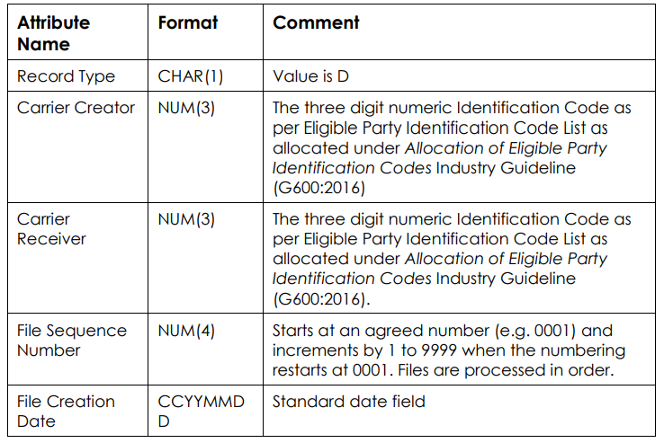
PLNR data is encoded as a fixed-format text file.
What is Re-targeting?
Re-Targeting is a fancy term of changing the date & time.
It’s typically more efficient to re-target a port than withdraw it and resubmit it.
For only two re-targets are allowed for each unique SNA. (Section 4.2.9)
The Australian telecommunications industry was deregulated in 1997, meaning customers could have telecommunications services through a Carriage Service Provider (CSP) of their choice.
In order to increase competition and make it easier to move to a different CSP, the ACMA (Or as they were then the ACA) declared that Local Numbers (Geo numbers / land lines) were a “Portable Service”. This meant that if a customer didn’t like their current Carriage Service Provider (CSP) they could give them the flick (making them the Loosing Carrier), move to a new CSP (Gaining Carrier) but keep their existing phone numbers by moving them to the new carrier in a process known as Local Number Portability (LNP).
The Local Number Portability (LNP) standard was first defined by Comms Alliance in 1999 in ACIF C540 and defines the process of moving numbers between Carriage Service Providers (CSPs), however 22 years later the process can still be a baffling system for many customers, end users and carrier staff to navigate.
Acronyms galore exist and often the porting teams involved themselves aren’t 100% sure what goes on in the porting process.
In 1997 ISDN was first still an emerging technology and porting was typically a customer moving from one PSTN / POTS line provided by one CSP to another PSTN / POTS line provided by a different CSP – a simple port.
Two processes were defined, one for managing simple ports involving moving one simple number from one CSP to another CSP – Called Simple Porting or “Cat A” – which made up the majority of porting requests at the time, and another process for everything else managed by a project manager from the Loosing and Gaining CSP called Complex Porting or “Cat C“.
Simple porting, classified as “Cat A” is used for porting single simple services (numbers).
The Cat A process can only be used for moving a “simple” standalone number – with no additional features – from one carrier to another.
The typical use case for Cat A port is moving a one copper PSTN / POTS line (Active line with no Fax Duet, Line Hunt, etc) from one carrier to another – as I said before, Cat A ports made up the majority of porting requests when the system was first introduced as the vast majority of services were copper POTS lines.
The process is automated at both ends, essentially the carriers send each other the numbers to be moved (more on that later) and their switches automatically process this and begin routing the number.
These ports are typically completed within a few days to a week and the customer gets a notification when the port is completed.
Cat C / Complex Number Porting
For all number porting that don’t meet the very specific requirements of Cat A aren’t met – and sometimes even if they are met, ports are processed as Cat C ports.
Cat C ports require a project manager at both the Gaining Carrier and the Losing Carrier to agree on the details for the port and the move the numbers, each using their own internal process.
Lead times on Cat C ports are long – and getting longer, so from submitting a port to it’s completion can take 90+ days, and there is no confirmation required to the customer to let them know the services have been ported successfully.
Administrative Process of Ports (CatA & CatC)
Strap yourself in for a whirlwind of acronyms…
The Code does not constrain two or more individual industry participants agreeing to different arrangements
Section 1.3.6
Because of this it means this is the minimum standard, some CSPs have improved upon this between each other, however there’s a bit of a catch 22 in that CSPs have no incentive to make porting numbers out easier, as they’re typically losing that customer, so the process is typically not improved upon in any meaningful way that makes the customer experience easier.
Without further ado, here’s what Cat A & Cat C ports look like under the hood…
Note: These all assume the Losing CSP is also the Donor CSP. More on that in the LNP FAQ and Call Routing posts.
Cat A – Simple Porting – Process
Summary
Cat A ports are automated – The process involves CSPs transferring formatted data between each other and the process that goes on for these ports.
The Losing CSP must use the Cat A process if the service meets the requirements to be ported under a Cat A and the Gaining Carrier has submitted it as a Cat A port. This means a Cat A port can’t be rejected by the losing carrier as not a valid Cat A port to be resubmitted as a Cat C port, if it does actually meet the requirements for Cat A porting. That said numbers that are valid in terms of Cat A can be submitted as a Cat C, this is often cheaper than submitting multiple Cat A porting requests when you have more than 5 or so services to be ported.
Here’s a brief summary of the process:
Customer requests port and details are validated
Simple Notification Advice (SNA) is sent to the Losing CSP via a Porting Notification Order (PNO) – Essentially a form send to the losing CSP of the intention to port the service
Losing CSP sends back SNA Confirmation Advice to confirm the service can be ported
Electronic Cutover Advice (ECA) sent by gaining CSP to indicate gaining CSP wanting to initiate port
Losing CSP provides Donor Routing by essentially redirecting calls to the Gaining CSP
ECA Confirmation Advice sent by losing CSP to denote the service has been removed from the losing CSP’s network & number is with gaining CSP as far as they are concerned
Losing CSP updates a big text file (PLNR) with a list of numbers allocated to it, to show the numbers have been ported to a different carrier and indicates which carrier
We’ll talk about the technical process of how the data is transferred, what PLNR is and how routing is managed, later on.
In depth process:
Step 1 – Customer Authority
The Gaining CSP must obtain Customer’s Authority (CA) to port number (Section 4.1.2) – Typically this takes the form of a number porting form filled in by the customer, containing a list of numbers to port, account numbers with losing carrier and date.
If requested by the customer the Losing CSP must explain any costs / termination payments / contractual obligations to the customer (Section 4.1.4), however the Losing CSP cannot reject the port based upon an outstanding contract being in place.
Step 2 – Validation
Before anything technical happens, the Gaining CSP must validate the porting request is valid – this means verifying:
The requested numbers are able to be ported under the selected method (Cat A or Cat C)
Confirming the date of the Customer Authority is less than 90 days old
The requested numbers must be recorded
In practice these 3 steps are typically handled by a single form filled out by the customer in the first step. (Section 4.1.5)
If requested by the Losing CSP this Customer Authority information has to be given to the Losing CSP. This typically happens in cases of disputed ownership / management of a number.
Step 3 – The SNA PNO
Once the Gaining CSP is satisfied the port is valid, a Simple Notification Advice (SNA) is sent to the Losing CSP via a Porting Notification Order (PNO) (Section 4.2.2).
The PNO is essentially a form that includes:
Area Code & Telephone Number of service to be ported
Service Account number with Losing CSP
Porting Category set to Cat A
Date of Customer Authority
The Losing CSP must then validate this info, by checking: (Section 4.2.4)
The requested number is a Simple service (Meets the requirements of Cat A)
Is with the Losing CSP (Has not been ported to another carrier already)
Is not disconnected or pending disconnection at the time the SNA was submitted
The Customer Authority (CA) date is not more than 90 days old
Does not currently have a port request pending
After the Losing CSP has gone through this they will send back a SNA Confirmation Advice if the port request (SNA PNO) is valid or a SNA Reject Advice along with the phone number and reason for rejection if the port request is deemed invalid.
The confirmation, if SNA Confirmation Advice is received, is deemed valid for 30 days, after which the process would have to start again and the SNA PNO would have to be regenerated.
Step 4 – Electronic Cutover Advice (ECA)
After the Losing CSP sends back a SNA Confirmation Advice, the gaining carrier sends the Losing Carrier an Electronic Cutover Advice (ECA) via the Final Cutover Notification Interface (Section 4.2.24 ).
When the Losing CSP get the ECA it’s showtime. The Losing CSP checks that there’s a valid SNAin place for the number to be ported and that it’s less than 2 days old (Section 4.2.27).
If the Losing CSP is not satisfied they send back a ECA Reject Advice listing the reason for rejection within 15 minutes (Section 4.2.32).
If all looks good, the Losing Carrier sends the Gaining CSP back a ECA Confirmation Advice within 15 minutes (Section 4.2.33).
Now is when the magic happens – the Losing CSP “ports out” that number via their internal process, for this they provide temporary Donor Transit Routing – Essentially redirecting any calls that come into the ported number to the new carrier.
Finally the Losing CSP sends a Electronic Completion Advice (ECA) to confirm they’ve processed the port out from their network (Section 4.2.34).
Within a day of the port completing, the Losing CSP updates the Ported Local Number Registry (PLNR) to show the service has been ported out and the identifier of the gaining carrier the number has been ported to. PLNR is nothing more than a giant text file containing a list of all the numbers originally allocated to the Losing CSP and the carrier code they should now be routing to, this data is published so the other CSPs can read it.
Other CSPs read this PLNR data and update their routing tables, meaning the calls will route directly to the new Gaining CSP, and the Donor Routing can be removed on the Losing CSPs switch.
Cat C – Complex Porting – Process
Summary
Cat C ports are a manually project managed, and unlike Cat A are not automated.
This means that the Losing and Gaining CSP must both allocate a “project manager”, the two to liaise with each other (typically via email) to confirm the numbers can be ported and then find a suitable time to port the numbers, finally at the agreed upon date & time each side kicks off their own process to move the numbers and confirm when it’s done.
Porting Number Validation – PNV
Before a Cat C port can be initiated the PNV process is typically called upon to validate the port won’t get rejected. This isn’t mandatory but is often used as PNV is processed relatively quickly which means any issues with the services can be worked out prior to submitting the port request.
The submitted PNV request is very similar to the actual Cat C porting request (CNA), containing the customer’s details and list of services to be ported.
The losing CSP returns the list of numbers each with a response code denoting particulars of the service, and if rejected, a rejection code.
Response Codes:
Reason Code
Reason
P
Prime/Directory Service Number
A
Associated Service Numbers
S
Standalone Number
R
Reserved Number
D
Exchange based diversion
SS
Secondary Service linked to this Number (e.g. DSL)
Reject Codes:
Code
Reason
1
Invalid Customer Authorization date
Whole Request
2
Insufficient information supplied
Whole Request
3
Telephone Number appears to belong to a completely different end customer
Per Number
4
Telephone Numbers relate to cancelled services or services pending cancellation
Per Number
5
Missing / invalid PNV Sequence Number
Per Number
6
Telephone Numbers in the PNV request relate to services which are billed by a service provider other than the Losing Carrier.
Per Number
7
Telephone Numbers are not found / not present on Losing Carrier’s Network
Per Number
(Section 4.3.8)
It’s worth noting the main reason PNV is used so heavily in Cat C ports is if a batch of numbers / services are requested to be ported in a single Cat C porting request, if any one of those numbers gets rejected the whole port will need to be resubmitted, hence it being important that before submitting the numbers to be ported, the Gaining CSP verifies they can be ported via the PNV process.
The PNV does not guarantee a physical audit of the services, but rather an audit of available electronic data by the losing CSP. It’s also only valid for the day of issue, so services can change between a PNV coming back clear and the port request being rejected.
99% of PNV requests should be processed within 5 business days. (Section 4.3.9)
Step 1 – Complex Notification Advice (CNA)
To initiate the port the gaining CSP submits a Complex Notification Advice(CNA) to the losing CSP.
This contains all the data you’d expect, including customer’s details and the list of services/numbers to be ported, along with a batch number that’s unique to the Gaining CSP (Like a ticket / request number) and Gaining CSP’s Project Manager – The staff member as the Gaining CSP that will be responsible for the port.
Upon receipt, the Losing CSP sends back a CNA Receipt Advice to confirm they’ve received and begins validating the CNA in a process very similar to the PNV process. (Section 4.4.1)
Step 2 – CNA Confirmation Advice
If verification fails and the CNA request is deemed not valid the CNA is rejected by the Losing CSP, who sends back a CNA Reject Advice response. This response will contain a list of services and the reject code for each rejected service as per the PNV process.
If the CNA is deemed valid, the Losing CSP responds with a CNA Confirmation Advice message, containing the Losing CSP’s project manager for this port, along with the Gaining CSP’s batch number to the Gaining CSP.
This is sent in a batch file along with other CNA Confirmation Advice messages within 5 days. (Section 4.4.6)
Step 3 – Complex Cutover Advice (CCA)
Once the Gaining CSP has the CNA Confirmation Advice the project manager for the port at the Gaining CSP contacts the nominated project manager at the Losing CSP and the two have to agree on a cutover date and time for the port. (Section 4.4.8)
The agreed date and time of the port is sent by the Gaining CSP to the Losing CSP in the from of a Complex Cutover Advice (CCA) containing the Gaining CSP batch number and agreed date & time. (Section 4.4.27)
If the details of the CCA are valid from the Losing CSP’s perspective, the Losing CSP sends back CCA Confirmation Advice to confirm receipt.
Step 4 – The Porting
At the agreed upon date & time both CSPs are to execute the port from their organization’s perspective.
Typically the losing CSP provides Donor Transit Routing forwarding / redirecting calls to the ported out number to the new CSP.
There is no completion advice and no verification the port has been completed successfully required by the code. (Section 4.4.48)
Within a day of the port completing, the Losing CSP updates the Ported Local Number Registry (PLNR).
Other CSPs read this PLNR data and update their routing tables, meaning the calls will route directly to the new Gaining CSP, and the Donor Routing can be removed on the Losing CSPs switch.
On a PCM (G.711) RTP packet the payload is typically 160 bytes per packet.
But the total size of the frame on the wire is typically ~214 bytes, to carry a 160 byte payload that means 25% of the data being carried is headers.
This is fine for VoIP services operating over fixed lines, but when we’re talking about VoLTE / IMS and the traffic is being transferred over Radio Access Networks with limited bandwidth / resources, it’s important to minimize this as much as possible.
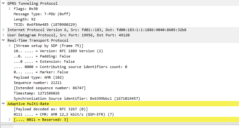
IMS uses the AMR codec, where the RTP payload for each packet is around 90 bytes, meaning up to two thirds of the packet on the wire (Or in this case the air / Uu interface) is headers.
Using ROHC the size of the headers are cut down to only 4-5 bytes, this is because the IPv4 headers, UDP headers and RTP headers are typically the same in each packet – with only the RTP Sequence number, RTP timestamp IPv4 & UDP checksum and changing between frames.
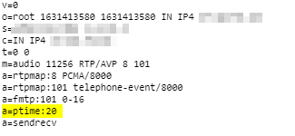
ptime is the packetization timer in VoIP, it’s set in the SDP message and defines the length of each RTP packet that’s sent;
This gives the length of time in milliseconds represented by the media in a packet. This is probably only meaningful for audio data, but may be used with other media types if it makes sense. It should not be necessary to know ptime to decode RTP or vat audio, and it is intended as a recommendation for the encoding/packetisation of audio. It is a media-level attribute, and it is not dependent on charset.
A lower ptime value leads to more packet per second, while longer ptime leads to fewer packets per second.
In a Toll Quality (TDM) network 8000 samples per second are taken, this is reflected in PCM (Pulse Code Modulation) encoding of the data, see in PCMA / G.711 a-law for example.
But if each of these 8,000 samples per second were sent on an individual packet, we’d be seeing a huge number of tiny RTP packets where the header is a lot larger than the payload.
Instead endpoints generally wait until they’ve got a certain number of theses samples and then send them at once, every X milliseconds as defined by the ptime value.
A ptime of 1000ms would mean 1 packet per second.
A ptime of 20ms would mean 50 packets per second.
A ptime of 50ms would mean 20 packets per second.
ptime headaches
Some VoIP endpoints have issues with varied ptime (*cough Cisco SPA series cough*), and if you’re interconnecting with other carrier networks you have no real control as to what ptime endpoints use (except if you have a B2Bua that can resample / restuff the packets, or you use maxptime which really just limits more than fixes) so it’s worth understanding well.
International carrier trunks often have higher ptime values as they're often dealing with lower quality links, so they want to cut down the packets per second and often have jitter buffers in place to compensate for poor quality links.
RFC4566 (the second version of SDP) introduced the maxptime value.
This optional header in the SDP body allows an endpoint to specify the maximum ptime value it supports.
Older endpoints often don’t have much memory or processing power, so have very small buffers to store the received audio in before playing it to the user, and store the audio to be transmitted before sending it down the wire.
Mismatched ptime or a ptime that’s out of bounds for one endpoint can lead to some strange issues. Often an endpoint will ring, answer the call and even get a 200 OK, but immediately followed by a BYE from the incompatible end instead of an ACK.
In the initial INVITE ptime is not mandatory, meaning you may not know the caller has limits to the ptime values they can support, and the endpoint hangs up the calls straight after the 200 OK.
Identifying these issues may take some time, but here’s some good places to look:
SDP ptime value on INVITE and 200 OK
Time between RTP packets
Timestamp difference between RTP packets
Although it seems pretty self evident, if your endpoint only supports up to 20ms ptime, set the maxptime header to 20ms. You’d be surprised how often this isn’t the case.
That’s obviously a bit of a problem, as we build out our network we might have a series of load balancers that send traffic to a pool of Registrars, but according to RFC3261 this can’t be done, the SIP REGISTER request would need to go direct to one of these Registrars.
To get around this the SIP Path extensions, officially called “Session Initiation Protocol (SIP) Extension Header Field for Registering Non-Adjacent Contacts” (catchy title) was defined under RFC 3327.
An additional header is introduced called “Path:” for each proxy between the UA and the Registrar,
As the SIP REGISTER request passes through each proxy, each proxy appends the Path header with the value of it’s own SIP URI.
Let’s take a look at an example call flow from [email protected] who sends his REGISTER to atlanta.com, which is proxied by atlanta.com to registrar1.atlanta.com:
Bob to atlanta.com:
[email protected] > atlanta.com
      REGISTER sip:atlanta.com SIP/2.0
      Via: SIP/2.0/UDP 192.0.2.4:5060;branch=z9hG4bKnashds7
      To: Bob <sip:[email protected]>
      From: Bob <sip:[email protected]>;tag=456248
      Call-ID: 843817637684230@998sdasdh09
      CSeq: 1826 REGISTER
      Contact: <Bob <sip:[email protected]>>
      Supported: path
The REGISTER request is received by atlanta.com, which forwards it to registrar1.atlanta.com after adding it’s own URI as a Path header.
ENUM was going to change telephone routing. No longer would you need to pay a carrier to take your calls across the PSTN, but rather through the use of DNS your handset would look up a destination and route in a peer to peer fashion.
Number porting would just be a matter of updating NAPTR records, almost all calls would be free as there’s no way/need to charge and media would flow directly from the calling party to the called party.
In 2005 ACMA became the Tier 1 provider from RIPE for the ENUM zone 4.6.e164.arpa
A trial was run and Tier 2 providers were sought to administer the system and to verify ownership of services before adding NAPTR records for individual services and referral records for ranges / delegation.
In 2007 the trial ended with only two CSPs having signed up and a half a dozen test calls made between them.
Now, over a decade later as we prepare for the ISDN switch off, NBN is almost finished rolling out, the Comms Alliance porting specs remain as rigid as ever, it might be time to look again at ENUM in Australia…
I recently started working on an issue that I’d seen was to do with the HSS response to the MME on an Update Location Answer.
I took some Wireshark traces of a connection from the MME to the HSS, and compared that to a trace from a different HSS. (Amarisoft EPC/HSS)
The Update Location Answer sent by the Amarisoft HSS to the MME over the S6a (Diameter) interface includes an AVP for “Multiple APN Configuration” which has the the dedicated bearer for IMS, while the HSS in the software I was working on didn’t.
After a bit of bashing trying to modify the S6a responses, I decided I’d just implement my own Home Subscriber Server.
I’m a big fan of RTPengine, and I’ve written a bit about it in the past.
Let’s say we’re building an Australia wide VoIP network. It’s a big country with a lot of nothing in the middle. We’ve got a POP in each of Australia’s capital cities, and two core softswitch clusters, one in Melbourne and one in Sydney.
These two cores will work fine, but a call from a customer in Perth, WA to another customer in Perth, WA would mean their RTP stream will need to go across your inter-caps to Sydney or Melbourne only to route back to Perth.
That’s 3,500Km each way, which is going to lead to higher latency, wasted bandwidth and decreased customer experience.
What if we could have an RTPengine instance in our Perth POP, handling RTP proxying for our Perth customers? Another in Brisbane, Canberra etc, all while keeping our complex expensive core signalling in just the two locations?
RTPengine to the rescue!
Preparing our RTPEngine Instances
In each of our POPs we’ll spin up a box with RTPengine,
The only thing we’d do differently is set the listen-ng value to be 0.0.0.0:2223 and the interface to be the IP of the box.
By setting the listen-ng value to 0.0.0.0:2223 it’ll mean that RTPengine’s management port will be bound to any IP, so we can remotely manage it via it’s ng-control protocol, using the rtpengine Kamailio module.
Naturally you’d limit access to port 2223 only to allowed devices inside your network.
Next we’ll need to add the details of each of our RTP engine instances to MySQL, I’ve used a different setid for each of the RTPengines. I’ve chosen to use the first digit of the Zipcode for that state (WA’s Zipcodes / Postcodes are in the format 6xxx while NSW postcodes are look like 2xxx), we’ll use this later when we select which RTPengine instances to use.
I’ve also added localhost with setid of 0, we’ll use this as our fallback route if it’s not coming from Australia.
Bingo, we’re connected to three RTPengine instances,
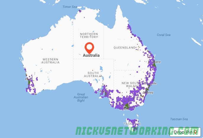
Next up we’ll use the Geoip2 module to determine the source of the traffic and route to the correct, I’ve touched upon the Geoip2 module’s basic usage in the past, so if you’re not already familiar with it, read up on it’s usage and we’ll build upon that.
We’ll load GeoIP2 and run some checks in the initial request_route{} block to select the correct RTPengine instance:
        if(geoip2_match("$si", "src")){
                if($gip2(src=>cc)=="AU"){
                        $var(zip) =  $gip2(src=>zip);
                        $avp(setid) = $(var(zip){s.substr,0,1});
                        xlog("rtpengine setID is $avp(setid)");
                }else{
                        xlog("GeoIP not in Australia - Using default RTPengine instance");
                        set_rtpengine_set("0");
                }
        }else{
                xlog("No GeoIP Match - Using default RTPengine instance");
                set_rtpengine_set("0");
        }
In the above example if we have a match on source, and the Country code is Australia, the first digit of the ZIP / Postcode is extracted and assigned to the AVP “setid” so RTPengine knows which set ID to use.
In practice an INVITE from an IP in WA returns setID 6, and uses our RTPengine in WA, while one from NSW returns 2 and uses one in NSW. In production we’d need to setup rules for all the other states / territories, and generally have more than one RTPengine instance in each location (we can have multiple instances with the same setid).
Hopefully you’re starting to get an idea of the fun and relatively painless things you can achieve with RTPengine and Kamailio!
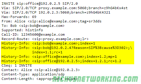
The History Info extension defined in RFC7044 sets a way for an INVITE to include where the session (call) has been before that.
For example a call may be made to a desk phone, which is forwarded (302) to a home phone. The History Info extension would add a History Info header to the INVITE to the home phone, denoting the call had come to it via the desk phone.
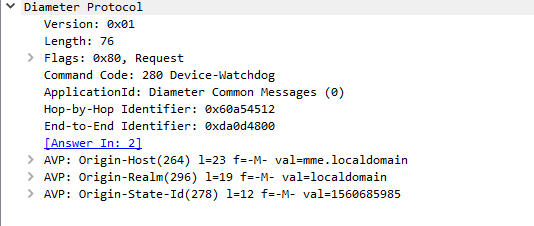
Each Diameter packet has at a the following headers:
Version
This 1 byte field is always (as of 2019) 0x01 (1)
Length
3 bytes containing the total length of the Diameter packet and all it’s contained AVPs.
This allows the receiver to know when the packet has ended, by reading the length and it’s received bytes so far it can know when that packet ends.
Flags
Flags allow particular parameters to be set, defining some possible options for how the packet is to be handled by setting one of the 8 bits in the flags byte, for example Request Set, Proxyable, Error, Potentially Re-transmitted Message,
Command Code
Each Diameter packet has a 3 byte command code, that defines the method of the request,
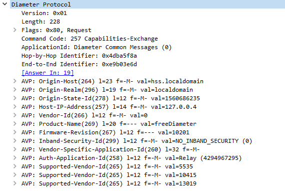
The IETF have defined the basic command codes in the Diameter Base Protocol RFC, but many vendors have defined their own command codes, and users are free to create and define their own, and even register them for public use.
To allow vendors to define their own command codes, each command code is also accompanied by the Application ID, for example the command code 257 in the base Diameter protocol translates to Capabilities Exchange Request, used to specify the capabilities of each Diameter peer, but 257 is only a Capabilities Exchange Request if the Application ID is set to 0 (Diameter Base Protocol).
If we start developing our own applications, we would start with getting an Application ID, and then could define our own command codes. So 257 with Application ID 0 is Capabilities Exchange Request, but command code 257 with Application ID 1234 could be a totally different request.
Hop-By-Hop Identifier
The Hop By Hop identifier is a unique identifier that helps stateful Diameter proxies route messages to and fro. A Diameter proxy would record the source address and Hop-by-Hop Identifier of a received packet, replace the Hop by Hop Identifier with a new one it assigns and record that with the original Hop by Hop Identifier, original source and new Hop by Hop Identifier.
End-to-End Identifier
Unlike the Hop-by-Hop identifier the End to End Identifier does not change, and must not be modified, it’s used to detect duplicates of messages along with the Origin-Host AVP.
AVPs
The real power of Diameter comes from AVPs, the base protocol defines how to structure a Diameter packet, but can’t convey any specific data or requests, we put these inside our Attribute Value Pairs.
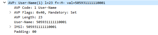
Let’s take a look at a simple Diameter request, it’s got all the boilerplate headers we talked about, and contains an AVP with the username.
Here we can see we’ve got an AVP with AVP Code 1, containing a username
Let’s break this down a bit more.
AVP Codes are very similar to the Diameter Command Codes/ApplicationIDs we just talked about.
Combined with an AVP Vendor ID they define the information type of the AVP, some examples would be Username, Session-ID, Destination Realm, Authentication-Info, Result Code, etc.
AVP Flags are again like the Diameter Flags, and are made up a series of bits, denoting if a parameter is set or not, at this stage only the first two bits are used, the first is Vendor Specific which defines if the AVP Code is specific to an AVP Vendor ID, and the second is Mandatory which specifies the receiver must be able to interpret this AVP or reject the entire Diameter request.
AVP Length defines the length of the AVP, like the Diameter length field this is used to delineate the end of one AVP.
AVP Vendor ID
If the AVP Vendor Specific flag is set this optional field specifies the vendor ID of the AVP Code used.
AVP Data
The payload containing the actual AVP data, this could be a username, in this example, a session ID, a domain, or any other value the vendor defines.
AVP Padding
AVPs have to fit on a multiple of a 32 bit boundary, so padding bits are added to the end of a packet if required to total the next 32 bit boundary.
3GPP selected Diameter protocol to take care of Authentication, Authorization, and Accounting (AAA).
It’s typically used to authenticate users on a network, authorize them to use services they’re allowed to use and account for how much of the services they used.
In a EPC scenario the Authentication function takes the form verifying the subscriber is valid and knows the K & OP/OPc keys for their specific IMSI.
The Authorization function checks to find out which features, APNs, QCI values and services the subscriber is allowed to use.
The Accounting function records session usage of a subscriber, for example how many sessional units of talk time, Mb of data transferred, etc.
Diameter Packets are pretty simple in structure, there’s the packet itself, containing the basic information in the headers you’d expect, and then a series of one or more Attribute Value Pairs or “AVPs”.
These AVPs are exactly as they sound, there’s an attribute name, for example username, and a value, for example, “Nick”.
This could just as easily be for ordering food; we could send a Diameter packet with an imaginary command code for Food Order Request, containing a series of AVPs containing what we want. The AVPs could belike Food: Hawian Pizza, Food: Garlic Bread, Drink: Milkshake, Address: MyHouse. The Diameter server could then verify we’re allowed to order this food (Authorization) and charge us for the food (Accounting), and send back a Food Order Response containing a series of AVPs such as Delivery Time: 30 minutes, Price: $30.00, etc.
Diameter packets generally take the form of a request – response, for example a Capabilities Exchange Request contains a series of AVPs denoting the features supported by the requester, which is sent to a Diameter peer. The Diameter peer then sends back a Capabilities Exchange Response, containing a series of AVPs denoting the features that it supports.
Diameter is designed to be extensible, allowing vendors to define their own type of AVP and Diameter requests/responses and 3GPP have defined their own types of messages (Diameter Command Codes) and types of data to be transferred (AVP Codes).
LTE/EPC relies on Diameter and the 3GPP/ETSI defined AVP / Diameter Packet requests/responses to form the S6a Interface between an MME and a HSS, the Gx Interface between the PCEF and the PCRF, Cx Interface between the HSS and the CSCF, and many more interfaces used for Authentication in 3GPP networks.
NAT is still common in Voice networks, and while we’re all awaiting the full scale adoption of IPv6, it’s still going to be a thing for some time.
I thought I’d dive into some of the NAT “solutions” that are currently in use.
Old RFC 3489 Definitions
These were the first NAT implementations used, and are still often used today.
Full cone NAT
A request from a private address is mapped to a public address and a publicly available port.
Traffic can be sent from any external device to this public address / port combination, and will be sent the internal device.
This is often statically setup, where you’d log into your router and put a NAT rule saying “Traffic on Port 5060 I want forwarded to my desk phone on 192.168.1.2” for example, and is sometimes just called a “Port forward”.
This can work fine if you’ve just got one unchanging internal address, but starts to have issues with multiple devices or dynamically assigned IPs.
Restricted Cone NAT
A request from a private address is mapped to a public address.
Traffic sent to this public address from an allowed IP will be routed to the internal device, regardless of port used.
Port Restricted Cone
Like restricted cone but only a single port may be used, traffic sent to any other port will not be routed to the internal device.
Symmetric NAT
Each request to an external destination gets a unique Public IP / Port combination to be used only by that destination, and each new request with a different source port on the internal side, or different destination on the external side, sets up a new NAT path.
RFC 5389 NAT Definitions
Endpoint Independent Mapping
Each request to an external destination gets the same public IP address / Port combination used for the outbound traffic.
Return traffic from the external destination is routed based on the source address, to the internal IP of the originating user.
It’s possible to have multiple internal devices communicating with multiple external destinations, using the same public IP address / port combination for each of them.
The source IP address of the traffic back from the external destination is used to map the path back to the internal IP.
This is efficient (doesn’t need to keep using outbound ports on the public IP) but means that it’ll only work to the requested external destination’s IP.
If you register to a SIP server on one IP, and media comes in on another, an Endpoint Independent Mapping NAT will see you with one-way audio.
Address Dependant Mapping
Each request to an external destination gets a unique public IP address / port combination used for outbound traffic.
It is reused for packets sent to the same destination, regardless of which destination port is used.
Address and Port Dependant Mapping
Same as Address Dependant Mapping but a new mapping is created for each destination and port.
You’ll often see numbers listed in different formats, which often leads to confusion.
Australian SIP networks may format numbers in either 0NDC-SN or E.164 format, leading some confusion. There’s no “correct” way, ACMA format in 0-NDC-SN, while most Australian tier 1 carriers store the records in E.164 format.
There’s no clear standard, so it’s always best to ask.
Let’s say my number is in Melbourne and is 9123 4567,
This could be expressed in Subscriber Number (SN) format:
9123 4567
The problem is a caller from Perth calling that number wouldn’t get through to me, there’s a good chance they’d get a totally unrelated business.
To stop this we can add the National Destination Code (NDC), for Victoria / Tasmania this is 3, however when dialling domestically a 0 is prefixed.
The leading 0 is a carry over from the days of step-by-step based switching, which had technical and physical design constraints that dictated the dialling plan we see today, which I’ll do a post about another day.
So to put it in 0-NDC-S format we’d list
03 9123 4567
But an international caller wouldn’t be able to reach this from their home country, they’d need to add the Country Code (CC) which for Australia is 61, so they’d dial the CC-NDC-SN
Sometimes this is listed with the plus symbol in front of it, like
+61 3 9123 4567
Each country has it’s own international dialling prefix, and the plus symbol is to be replaced by the international dialling prefix used in the calling country. In Australia, we replace the + with 0011, but it’s different from country to country.
We’ve talked a bit in the past few posts about keys, K and all it’s derivatives, such as Kenc, Kint, etc.
Each of these is derived from our single secret key K, known only to the HSS and the USIM.
To minimise the load on the HSS, the HSS transfers some of the key management roles to the MME, without ever actually revealing what the secret key K actually is to the MME.
This means the HSS is only consulted by the MME when a UE/Terminal attaches to the network, and not each time it attaches to different cell etc.
When the UE/Terminal first attaches to the network, as outlined in my previous post, the HSS also generates an additional key it sends to the MME, called K-ASME.
K-ASME is the K key derived value generated by the HSS and sent to the MME. It sands for “Access Security Management Entity” key.
When the MME has the K-ASME it’s then able to generate the other keys for use within the network, for example the Kenb key, used by the eNodeB to generate the keys required for communications.
The USIM generates the K-ASME itself, and as it’s got the same input parameters, the K-ASME generated by the USIM is the same as that generated by the HSS.
The USIM can then give the terminal the K-ASME key, so it can generate the same Kenb key required to generate keys for complete communications.
We’ve already touched on how subscribers are authenticated to the network, how the network is authenticated to subscribers.
Those functions are done “in the clear” meaning anyone listening can get a copy of the data transmitted, and responses could be spoofed or faked.
To prevent this, we want to ensure the data is ciphered (encrypted) and the integrity of the data is ensured (no one has messed with our packets in transmission or is sending fake packets).
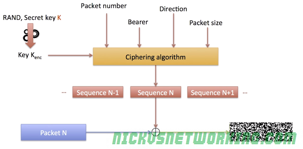
Ciphering of Messages
Before being transmitted over the Air interface (Uu) each packet is encrypted to prevent eavesdropping.
This is done by taking the plain text data and a ciphering sequence for that data of the same length as the packet and XORing two.
The terminal and the eNodeB both generate the same ciphering sequence for that data.
This means to get the ciphered version of the packet you simply XOR the Ciphering Sequence and the Plain text data.
To get the plain text from the ciphered packet you simply XOR the ciphered packet and ciphering sequence.
The Ciphering Sequence is made up of parts known only to the Terminal and the Network (eNB), meaning anyone listening can’t deduce the same ciphering sequence.
The Ciphering Sequence is derived from the following input parameters:
Key Kenc
Packet Number
Bearer Number
Direction (UL/DL)
Packet Size
Is is then ciphered using a ciphering algorithm, 3GPP define two options – AES or SNOW 3G. There is an option to not generate a ciphering sequence at all, but it’s not designed for use in production environments for obvious reasons.
Ciphering Sequences are never reused, the packet number increments with each packet sent, and therefore a new Cipher Sequence is generated for each.
Someone listening to the air interface (Uu) may be able to deduce packet size, direction and even bearer, but without the packet number and secret key Kenc, the data won’t be readable.
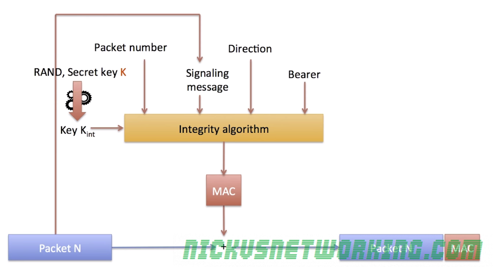
Data Integrity
By using the same ciphering sequence & XOR process outlined above, we also ensure that data has not been manipulated or changed in transmission, or that it’s not a fake message spoofing the terminal or the eNB.
Each frame contains the packet and also a “Message Authentication Code” or “MAC” (Not to be confused with media access control), a 32 bit long cryptographic hash of the contents of the packet.
The sender generates the MAC for each packet and appends it in the frame,
The receiver looks at the contents of the packet and generates it’s own MAC using the same input parameters, if the two MACs (Generated and received) do not match, the packet is discarded.
This allows the receiver to detect corrupted packets, but does not prevent a malicious person from sending their own fake packets,
To prevent this the MAC hash function requires other input parameter as well as the packet itself, such as the secret key Kint, packet number, direction and bearer.
By adding this we ensure that the packet was sourced from a sender with access to all this data – either the terminal or the eNB.
In my last post we discussed how the network authenticated a subscriber, now we’ll look at how a subscriber authenticates to a network. There’s a glaring issue there in that the MME could look at the RES and the XRES and just say “Yup, OK” even if the results differed.
To combat this LTE networks have mutual authentication, meaning the network authenticates the subscribers as we’ve discussed, and the subscribers authenticate the network.
To do this our HSS will take the same random key (RAND) we used to authenticate the subscriber, and using a different cryptographic function (called g) take the RAND, the K value and a sequence number called SQN, and using these 3 inputs, generate a new result we’ll call AUTN.
The HSS sends the RAND (same as RAND used to authenticate the subscriber) and the output of AUTN to the MME which forwards it to the eNB to the UE which passes the RAND and AUTH values to the USIM.
The USIM takes the RAND and the K value from the HSS, and it’s expected sequence number. With these 3 values it applies the cryptographic function g generates it’s own AUTN result.
If it matches the AUTN result generated by the HSS, the USIM has authenticated the network.
The USIM and the HSS contain the subscriber’s K key. The K key is a 128 bit long key that is stored on the subscriber’s USIM and in the HSS along with the IMSI.
The terminal cannot read the K key, neither can the network, it is never transmitted / exposed.
When the Terminal starts the attach procedure, it includes it’s IMSI, which is sent to the MME.
The MME then sends the the HSS a copy of the IMSI.
The HSS looks up the K key for that IMSI, and generates a random key called RAND.
The HSS and runs a cryptographic function (called f) using the input of RAND and K key for that IMSI, the result is called XRES (Expected result).
The HSS sends the output of this cryptographic function (XRES), and the random value (RAND) back to the MME.
The MME forwards the RAND value to the USIM (via eNB / Terminal), and stores a copy of the expected output of the cryptographic function.
The USIM take the RAND and the K key and performs the same cryptographic function the HSS did on it with the input of the K key and RAND value to generate it’s own result (RES).
The result of this same function (RES) is then sent from the USIM to the terminal which forwards it to the MME.
The MME and comparing the result the HSS generated (XRES) with the result the USIM generated. (RES)
If the two match it means both the USIM knows the K key, and is therefore the subscriber they’re claiming to be.
If the two do not match the UE is refused access to the network.