Tag Archives: 3GPP

Some thoughts on NRF Security in 5G Core

So I’ve been waxing lyrical about how cool in the NRF is, but what about how it’s secured?

A matchmaking service for service-consuming NFs to find service-producing NFs makes integration between them a doddle, but also opens up all sorts of attack vectors.

Theoretical Nasty Attacks (PoC or GTFO)

Sniffing Signaling Traffic:
A malicious actor could register a fake UDR service with a higher priority with the NRF. This would mean UDR service consumers (Like the AUSF or UDM) would send everything to our fake UDR, which could then proxy all the requests to the real UDR which has a lower priority, all while sniffing all the traffic.

Stealing SIM Credentials:
Brute forcing the SUPI/IMSI range on a UDR would allow the SIM Card Crypto values (K/OP/Private Keys) to be extracted.

Sniffing User Traffic:
A dodgy SMF could select an attacker-controlled / run UPF to sniff all the user traffic that flows through it.

Obviously there’s a lot more scope for attack by putting nefarious data into the NRF, or querying it for data gathering, and I’ll see if I can put together some examples in the future, but you get the idea of the mischief that could be managed through the NRF.

This means it’s pretty important to secure it.

OAuth2

3GPP selected to use common industry standards for HTTP Auth, including OAuth2 (Clearly lessons were learned from COMP128 all those years ago), however OAuth2 is optional, and not integrated as you might expect. There’s a little bit to it, but you can expect to see a post on the topic in the next few weeks.

3GPP Security Recommendations

So how do we secure the NRF from bad actors?

Well, there’s 3 options according to 3GPP:

Option 1 – Mutual TLS

Where the Client (NF) and the Server (NRF) share the same TLS info to communicate.

This is a pretty standard mechanism to use for securing communications, but the reliance on issuing certificates and distributing them is often done poorly and there is no way to ensure the person with the certificate, is the person the certificate was issued to.

3GPP have not specified a mechanism for issuing and securely distributing certificates to NFs.

Option 2 – Network Domain Security (NDS)

Split the network traffic on a logical level (VLANs / VRFs, etc) so only NFs can access the NRF.

Essentially it’s logical network segregation.

Option 3 – Physical Security

Split the network like in NDS but a physical layer, so the physical cables essentially run point-to-point from NF to NRF.

Thoughts?

What’s interesting is these are presented as 3 options, rather than the layered approach.

OAuth2 is used, but

Summary


NRF and NF shall authenticate each other during discovery, registration, and access token request. If the PLMN uses
protection at the transport layer as described in clause 13.1, authentication provided by the transport layer protection
solution shall be used for mutual authentication of the NRF and NF.
If the PLMN does not use protection at the transport layer, mutual authentication of NRF and NF may be implicit by
NDS/IP or physical security (see clause 13.1).
When NRF receives message from unauthenticated NF, NRF shall support error handling, and may send back an error
message. The same procedure shall be applied vice versa.
After successful authentication between NRF and NF, the NRF shall decide whether the NF is authorized to perform
discovery and registration.
In the non-roaming scenario, the NRF authorizes the Nnrf_NFDiscovery_Request based on the profile of the expected
NF/NF service and the type of the NF service consumer, as described in clause 4.17.4 of TS23.502 [8].In the roaming
scenario, the NRF of the NF Service Provider shall authorize the Nnrf_NFDiscovery_Request based on the profile of
the expected NF/NF Service, the type of the NF service consumer and the serving network ID.
If the NRF finds NF service consumer is not allowed to discover the expected NF instances(s) as described in clause
4.17.4 of TS 23.502[8], NRF shall support error handling, and may send back an error message.
NOTE 1: When a NF accesses any services (i.e. register, discover or request access token) provided by the NRF ,
the OAuth 2.0 access token for authorization between the NF and the NRF is not needed.

TS 133 501 – 13.3.1 Authentication and authorization between network functions and the NRF

Framed Routing in 5G

Previous generations of core mobile network, would only allocate a single IP address per UE (Well, two if dual-stack IPv4/IPv6 if you want to be technical). But one of the cool features in 5GC is the support for Framed Routing natively.

You could do this on several EPC platforms on LTE, but it’s support was always a bit shoe-horned in, and the UE was not informed of the framed addresses.

If you’ve worked in a wireline ISP you’re probably familiar with the concept of framed routing already, in short it’s one or more static routes, typically returned from a AAA server (Normally RADIUS) that are then routed to the subscriber.

Each subscriber gets allocated an IP by the network, but other IPs can also be routed to the subscriber, based on the network and CIDR mask.

So let’s say we allocate a public IP of 1.2.3.4/32 to our subscriber, but our subscriber is a fixed-wireless user running a business and they want a extra public IP Addresses.

How do we do this? With Framed Routing.

Now in our UDM we can add a “Framed IP”, and when the SMF sets up a session for our subscriber, the extra networks specified in the framed routes will get routed to that UE.

If we add 203.176.196.0/30 in our UDM for a subscriber, when the subscriber attaches the UPF will be setup to forward traffic to 1.2.3.4/32 and also traffic to 203.176.196.0/30 to the UE.

Update: I previously claimed:
Best of all this is signaled to the UE during the attach, so the UE is say a router, it becomes aware of the Framed IPs allocated to it.
This is incorrect! Thanks to Anonymous Telco Engineer from an Anonymous Nordic Country for pointing this out, it is not signaled to the UE.

More info in 3GPP TS 23.501 section 5.6.14 Support of Framed Routing.

Jaffa Cakes explain the nuances between Centralized vs Decentralized Online Charging in 3GPP Networks

While reading through the 3GPP docs regarding Online Charging, there’s a concept that can be a tad confusing, and that’s the difference between Centralized and Non-Centralized Charging architectures.

The overall purpose of online charging is to answer that deceptively simple question of “does the user have enough credit for this action?”.

In order to answer that question, we need to perform rating and unit determination.

Rating

Rating is just converting connectivity credit units into monetary units.

If you go to the supermarket and they have boxes of Jaffa Cakes at $2.50 each, they have rated a box of Jaffa Cakes at $2.50.

1 Box of Jaffa Cakes rated at $2.50 per box

In a non-snack-cake context, such as 3GPP Online Charging, then we might be talking about data services, for example $1 per GB is a rate for data.
Or for a voice calls a cost per minute to call a destination, such as is $0.20 per minute for a local call.

Rating is just working out the cost per connectivity unit (Data or Minutes) into a monetary cost, based on the tariff to be applied to that subscriber.

Unit Determination

The other key piece of information we need is the unit determination which is the calculation of the number of non-monetary units the OCS will offer prior to starting a service, or during a service.

This is done after rating so we can take the amount of credit available to the subscriber and calculate the number of non-monetary units to be offered.

Converting Hard-Currency into Soft-Snacks

In our rating example we rated a box of Jaffa Cakes at $2.50 per box. If I have $10 I can go to the shops and buy 4x boxes of Jaffa cakes at $2.50 per box. The cashier will perform unit determination and determine that at $2.50 per box and my $10, I can have 4 boxes of Jaffa cakes.

Again, steering away from the metaphor of the hungry author, Unit Determination in a 3GPP context could be determining how many minutes of talk time to be granted.
Question: At $0.20 per minute to a destination, for a subscriber with a current credit of $20, how many minutes of talk time should they be granted?
Answer: 100 minutes ($20 divided by $0.20 per minute is 100 minutes).

Or to put this in a data perspective,
Question: Subscriber has $10 in Credit and data is rated at $1 per GB. How many GB of data should the subscriber be allowed to use?
Answer: 10GB.

Putting this Together

So now we understand rating (working out the conversion of connectivity units into monetary units) and unit determination (determining the number of non-monetary units to be granted for a given resource), let’s look at the the Centralized and Decentralized Online Charging.

Centralized Rating

In Centralized Rating the CTF (Our P-GW or S-CSCF) only talk about non-monetary units.
There’s no talk of money, just of the connectivity units used.

The CTFs don’t know the rating information, they have no idea how much 1GB of data costs to transfer in terms of $$$.

For the CTF in the P-GW/PCEF this means it talks to the OCS in terms of data units (data In/out), not money.

For the CTF in the S-CSCF this means it only ever talks to the OCS in voice units (minutes of talk time), not money.

This means our rates only need to exist in the OCS, not in the CTF in the other network elements. They just talk about units they need.

De-Centralized Rating

In De-Centralized Rating the CTF performs the unit conversion from money into connectivity units.
This means the OCS and CTF talk about Money, with the CTF determining from that amount of money granted, what the subscriber can do with that money.

This means the CTF in the S-CSCF needs to have a rating table for all the destinations to determine the cost per minute for a call to a destination.

And the CTF in the P-GW/PCEF has to know the cost per octet transferred across the network for the subscriber.

In previous generations of mobile networks it may have been desirable to perform decentralized rating, as you can spread the load of calculating our the pricing, however today Centralized is the most common way to approach this, as ensuring the correct rates are in each network element is a headache.

Centralized Unit Determination

In Centralized Unit Determination the CTF tells the OCS the type of service in the Credit Control Request (Requested Service Units), and the OCS determines the number of non-monetary units of a certain service the subscriber can consume.

The CTF doesn’t request a value, just tells the OCS the service being requested and subscriber, and the OCS works out the values.

For example, the S-CSCF specifies in the Credit Control Request the destination the caller wishes to reach, and the OCS replies with the amount of talk time it will grant.

Or for a subscriber wishing to use data, the P-GW/PCEF sends a Credit Control Request specifying the service is data, and the OCS responds with how much data the subscriber is entitled to use.

De-Centralized Unit Determination

In De-Centralized Unit Determination, the CTF determines how many units are required to start the service, and requests these units from the OCS in the Credit Control Request.

For a data service,the CTF in the P-GW would determine how many data units it is requesting for a subscriber, and then request that many units from the OCS.

For a voice call a S-CSCF may request an initial call duration, of say 5 minutes, from the OCS. So it provides the information about the destination and the request for 300 seconds of talk time.

Session Charging with Unit Reservation (SCUR)

Arguably the most common online charging scenario is Session Charging with Unit Reservation (SCUR).

SCUR relies on reserving an amount of funds from the subscriber’s balance, so no other services can those funds and translating that into connectivity units (minutes of talk time or data in/out based on the Requested Session Unit) at the start of the session, and then subsequent requests to debit the reserved amount and reserve a new amount, until all the credit is used.

This uses centralized Unit Determination and centralized Rating.

Let’s take a look at how this would look for the CTF in a P-GW/PCEF performing online charging for a subscriber wishing to use data:

  1. Session Request: The subscriber has attached to the network and is requesting service.
  2. The CTF built into the P-GW/PCEF sends a Credit Control Request: Initial Request (As this subscriber has just attached) to the OCS, with Requested Service Units (RSU) of data in/out to the OCS.
  3. The OCS performs rating and unit determination, and according to it’s credit risk policies, and a whole lot of other factors, comes back with an amount of data the subscriber can use, and reserves the amount from the account.
    (It’s worth noting at this point that this is not necessarily all of the subscriber’s credit in the form of data, just an amount the OCS is willing to allocate. More data can be requested once this allocated data is used up.)
  4. The OCS sends a Credit Control Answer back to our P-GW/PCEF. This contains the Granted Service Unit (GSU), in our case the GSU is data so defines much data up/down the user can transfer. It also may include a Validity Time (VT), which is the number of seconds the Credit Control Answer is valid for, after it’s expired another Credit Control Request must be sent by the CTF.
  5. Our P-GW/PCEF processes this, starts measuring the data used by the subscriber for reporting later, and sets a timer for the Validity Time to send another CCR at that point.
    At this stage, our subscriber is able to start using data.
  1. Some time later, either when all the data allocated in the Granted Service Units has been consumed, or when the Validity Time has expired, the CTF in the P-GW/PCEF sends another Credit Control Request: Update, and again includes the RSU (Requested Service Units) as data in/out, and also a USU (Used Service Units) specifying how much data the subscriber has used since the first Credit Control Answer.
  2. The OCS receives this information. It compares the Used Session Units to the Granted Session Units from earlier, and with this is able to determine how much data the subscriber has actually used, and therefore how much credit that equates to, and debit that amount from the account.
    With this information the OCS can reserve more funds and allocate another GSU (Granted Session Unit) if the subscriber has the required balance. If the subscriber only has a small amount of credit left the FUI (Final Unit Indication AVP) is set to determine this is all the subscriber has left in credit, and if this is exhausted to end the session, rather than sending another Credit Control Request.
  3. The Credit Control Answer with new GSU and the FUI is sent back to the P-GW/PCEF
  4. The P-GW/PCEF allows the session to continue, again monitoring used traffic against the GSU (Granted Session Units).
  1. Once the subscriber has used all the data in the Granted Session Units, and as the last CCA included the Final Unit Indicator, the CTF in the P-GW/PCEF knows it can’t just request more credit in the form of a CCR Update, so cuts of the subscribers’s session.
  2. The P-GW/PCEF then sends a Credit Control Request: Termination Request with the final Used Service Units to the OCS.
  3. The OCS debits the used service units from the subscriber’s balance, and refunds any unused credit reservation.
  4. The OCS sends back a Credit Control Answer which may include the CI value for Credit Information, to denote the cost information which may be passed to the subscriber if required.

PS Data Off

Imagine a not-too distant future, one without flying cars – just one where 2G and 3G networks have been switched off.

And the imagine a teenage phone user, who has almost run out of their prepaid mobile data allocation, and so has switched mobile data off, or a roaming scenario where the user doesn’t want to get stung by an unexpectedly large bill.

In 2G/3G networks the Circuit Switched (Voice & SMS) traffic was separate to the Packet Switched (Mobile Data).

This allowed users to turn of mobile data (GPRS/HSDPA), etc, but still be able to receive phone calls and send SMS, etc.

With LTE, everything is packet switched, so turning off Mobile Data would cut off VoLTE connectivity, meaning users wouldn’t be able to make/recieve calls or SMS.

In 3GPP Release 14 (2017) 3GPP introduced the PS Data Off feature.

This feature is primarily implemented on the UE side, and simply blocks uplink user traffic from the UE, while leaving other background IP services, such as IMS/VoLTE and MMS, to continue working, even if mobile data is switched off.

The UE can signal to the core it is turning off PS Data, but it’s not required to, so as such from a core perspective you may not know if your subscriber has PS Data off or not – The default APN is still active and in the implementations I’ve tried, it still responds to ICMP Pings.

IMS Registration stays in place, SMS and MMS still work, just the UE just drops the requests from the applications on the device (In this case I’m testing with an Android device).

What’s interesting about this is that a user may still find themselves consuming data, even if data services are turned off. A good example of this would be push notifications, which are sent to the phone (Downlink data). The push notification will make it to the UE (or at least the TCP SYN), after all downlink services are not blocked, however the response (for example the SYN-ACK for TCP) will not be sent. Most TCP stacks when ignored, try again, so you’ll find that even if you have PS Data off, you may still use some of your downlink data allowance, although not much.

The SIM EF 3GPPPSDATAOFF defines the services allowed to continue flowing when PS Data is off, and the 3GPPPSDATAOFFservicelist EF lists which IMS services are allowed when PS Data is off.

Usually at this point, I’d include a packet capture and break down the flow of how this all looks in signaling, but when I run this in my lab, I can’t differentiate between a PS Data Off on the UE and just a regular bearer idle timeout… So have an irritating blinking screenshot instead…

The PLMN Problem for Private LTE / 5G

So it’s the not to distant future and the pundits vision of private LTE and 5G Networks was proved correct, and private networks are plentiful.

But what PLMN do they use?

The PLMN (Public Land Mobile Network) ID is made up of a Mobile Country Code + Mobile Network Code. MCCs are 3 digits and MNCs are 2-3 digits. It’s how your phone knows to connect to a tower belonging to your carrier, and not one of their competitors.

For example in Australia (Mobile Country Code 505) the three operators each have their own MCC. Telstra as the first licenced Mobile Network were assigned 505/01, Optus got 505/02 and VHA / TPG got 505/03.

Each carrier was assigned a PLMN when they started operating their network. But the problem is, there’s not much space in this range.

The PLMN can be thought of as the SSID in WiFi terms, but with a restriction as to the size of the pool available for PLMNs, we’re facing an IPv4 exhaustion problem from the start if we’re facing an explosion of growth in the space.

Let’s look at some ways this could be approached.

Everyone gets a PLMN

If every private network were to be assigned a PLMN, we’d very quickly run out of space in the range. Best case you’ve got 3 digits, so only space for 1,000 networks.

In certain countries this might work, but in other areas these PLMNs may get gobbled up fast, and when they do, there’s no more. New operators will be locked out of the market.

Loaner PLMNs

Carriers already have their own PLMNs, they’ve been using for years, some kit vendors have been assigned their own as well.

If you’re buying a private network from an existing carrier, they may permit you to use their PLMN,

Or if you’re buying kit from an existing vendor you may be able to use their PLMN too.

But what happens then if you want to move to a different kit vendor or another service provider? Do you have to rebuild your towers, reconfigure your SIMs?

Are you contractually allowed to continue using the PLMN of a third party like a hardware vendor, even if you’re no longer purchasing hardware from them? What happens if they change their mind and no longer want others to use their PLMN?

Everyone uses 999 / 99

The ITU have tried to preempt this problem by reallocating 999/99 for use in Private Networks.

The problem here is if you’ve got multiple private networks in close proximity, especially if you’re using CBRS or in close proximity to other networks, you may find your devices attempting to attach to another network with the same PLMN but that isn’t part of your network,

Mobile Country or Geographical Area Codes
Note from TSB
Following the agreement on the Appendix to Recommendation ITU-T E.212 on “shared E.212 MCC 999 for internal use within a private network” at the closing plenary of ITU-T SG2 meeting of 4 to 13 July 2018, upon the advice of ITU-T Study Group 2, the Director of TSB has assigned the Mobile Country Code (MCC) “999” for internal use within a private network. 

Mobile Network Codes (MNCs) under this MCC are not subject to assignment and therefore may not be globally unique. No interaction with ITU is required for using a MNC value under this MCC for internal use within a private network. Any MNC value under this MCC used in a network has
significance only within that network. 

The MNCs under this MCC are not routable between networks. The MNCs under this MCC shall not be used for roaming. For purposes of testing and examples using this MCC, it is encouraged to use MNC value 99 or 999. MNCs under this MCC cannot be used outside of the network for which they apply. MNCs under this MCC may be 2- or 3-digit.

(Recommendation ITU-T E.212 (09/2016))

The Crystal Ball?

My bet is we’ll see the ITU allocate an MCC – or a range of MCCs – for private networks, allowing for a pool of PLMNs to use.

When deploying networks, Private network operators can try and pick something that’s not in use at the area from a pool of a few thousand options.

The major problem here is that there still won’t be an easy way to identify the operator of a particular network; the SPN is local only to the SIM and the Network Name is only present in the NAS messaging on an attach, and only after authentication.

If you’ve got a problem network, there’s no easy way to identify who’s operating it.

But as eSIMs become more prevalent and BIP / RFM on SIMs will hopefully allow operators to shift PLMNs without too much headache.

IMS Routing with iFCs

SIP routing is complicated, there’s edge cases, traffic that can be switched locally and other traffic that needs to be proxied off to another Proxy or Application server. How can you define these rules and logic in a flexible way, that allows these rules to be distributed out to multiple different network elements and adjusted on a per-subscriber basis?

Enter iFCs – The Initial Filter Criteria.

iFCs are XML encoded rules to define which servers should handle traffic matching a set of rules.

Let’s look at some example rules we might want to handle through iFCs:

  • Send all SIP NOTIFY, SUBSCRIBE and PUBLISH requests to a presence server
  • Any Mobile Originated SMS to an SMSc
  • Calls to a specific destination to a MGC
  • Route any SIP INVITE requests with video codecs present to a VC bridge
  • Send calls to Subscribers who aren’t registered to a Voicemail server
  • Use 3rd party registration to alert a server that a Subscriber has registered

All of these can be defined and executed through iFCs, so let’s take a look,

iFC Structure

iFCs are encoded in XML and typically contained in the Cx-user-data AVP presented in a Cx Server Assignment Answer response.

Let’s take a look at an example iFC and then break down the details as to what we’re specifying.

<InitialFilterCriteria>
    <Priority>10</Priority>
    <TriggerPoint>
        <ConditionTypeCNF>1</ConditionTypeCNF>
        <SPT>
            <ConditionNegated>0</ConditionNegated>
            <Group>0</Group>
            <Method>MESSAGE</Method>
        </SPT>
        <SPT>
            <ConditionNegated>0</ConditionNegated>
            <Group>1</Group>
            <SessionCase>0</SessionCase>
        </SPT>
    </TriggerPoint>
    <ApplicationServer>
        <ServerName>sip:smsc.mnc001.mcc001.3gppnetwork.org:5060</ServerName>
        <DefaultHandling>0</DefaultHandling>
    </ApplicationServer>
</InitialFilterCriteria>

Each rule in an iFC is made up of a Priority, TriggerPoint and ApplicationServer.

So for starters we’ll look at the Priority tag.
The Priority tag allows us to have multiple-tiers of priority and multiple levels of matching,
For example if we had traffic matching the conditions outlined in this rule (TriggerPoint) but also matching another rule with a lower priority, the lower priority rule would take precedence.

Inside our <TriggerPoint> tag contains the specifics of the rules and how the rules will be joined / matched, which is what we’ll focus on predominantly, and is followed by the <ApplicationServer> which is where we will route the traffic to if the TriggerPoint is matched / triggered.

So let’s look a bit more about what’s going on inside the TriggerPoint.

Each TriggerPoint is made up of Service Point Trigger (SPTs) which are individual rules that are matched or not matched, that are either combined as logical AND or logical OR statements when evaluated.

By using fairly simple building blocks of SPTs we can create a complex set of rules by joining them together.

Service Point Triggers (SPTs)

Let’s take a closer look at what goes on in an SPT.
Below is a simple SPT that will match all SIP requests using the SIP MESSAGE method request type:

        <SPT>
            <ConditionNegated>0</ConditionNegated>
            <Group>0</Group>
            <Method>MESSAGE</Method>
        </SPT>

So as you may have guessed, the <Method> tag inside the SPT defines what SIP request method we’re going to match.

But Method is only one example of the matching mechanism we can use, but we can also match on other attributes, such as Request URI, SIP Header, Session Case (Mobile Originated vs Mobile Terminated) and Session Description such as SDP.

Or an example of a SPT for anything Originating from the Subscriber utilizing the <SessionCase> tag inside the SPT.

        <SPT>
            <ConditionNegated>0</ConditionNegated>
            <Group>0</Group>
            <SessionCase>0</SessionCase>
        </SPT>

Below is another SPT that’s matching any requests where the request URI is sip:[email protected] by setting the <RequestURI> tag inside the SPT:

        <SPT>
            <ConditionNegated>0</ConditionNegated>
            <Group>0</Group>
            <RequestURI>sip:[email protected]</RequestURI>
        </SPT>

We can match SIP headers, either looking for the existence of a header or the value it is set too,

        <SPT>
            <ConditionNegated>0</ConditionNegated>
            <Group>0</Group>
            <SIPHeader>
              <Header>To</Header>
              <Content>"Nick"</Content>
            </SIPHeader>
        </SPT>

Having <Header> will match if the header is present, while the optional Content tag can be used to match

In terms of the Content this is matched using Regular Expressions, but in this case, not so regular regular expressions. 3GPP selected Extended Regular Expressions (ERE) to be used (IEEE POSIX) which are similar to the de facto standard PCRE Regex, but with a few fewer parameters.

Condition Negated

The <ConditionNegated> tag inside the SPT allows us to do an inverse match.

In short it will match anything other than what is specified in the SPT.

For example if we wanted to match any SIP Methods other than MESSAGE, setting <ConditionNegated>1</ConditionNegated> would do just that, as shown below:

        <SPT>
            <ConditionNegated>1</ConditionNegated>
            <Group>0</Group>
            <Method>MESSAGE</Method>
        </SPT>

And another example of ConditionNegated in use, this time we’re matching anything where the Request URI is not sip:[email protected]:

        <SPT>
            <ConditionNegated>1</ConditionNegated>
            <Group>0</Group>
            <RequestURI>sip:[email protected]</RequestURI>
        </SPT>

Finally the <Group> tag allows us to group together a group of rules for the purpose of evaluating.
We’ll go into it more in in the below section.

ConditionTypeCNF / ConditionTypeDNF

As we touched on earlier, <TriggerPoints> contain all the SPTs, but also, very importantly, specify how they will be interpreted.

SPTs can be joined in AND or OR conditions.

For some scenarios we may want to match where METHOD is MESSAGE and RequestURI is sip:[email protected], which is different to matching where the METHOD is MESSAGE or RequestURI is sip:[email protected].

This behaviour is set by the presence of one of the ConditionTypeCNF (Conjunctive Normal Form) or ConditionTypeDNF (Disjunctive Normal Form) tags.

If each SPT has a unique number in the GroupTag and ConditionTypeCNF is set then we evaluate as AND.

If each SPT has a unique number in the GroupTag and ConditionTypeDNF is set then we evaluate as OR.

Let’s look at how the below rule is evaluated as AND as ConditionTypeCNF is set:

<InitialFilterCriteria>
    <Priority>10</Priority>
    <TriggerPoint>
        <ConditionTypeCNF>1</ConditionTypeCNF>
        <SPT>
            <ConditionNegated>0</ConditionNegated>
            <Group>0</Group>
            <Method>MESSAGE</Method>
        </SPT>
        <SPT>
            <ConditionNegated>0</ConditionNegated>
            <Group>1</Group>
            <SessionCase>0</SessionCase>
        </SPT>
    </TriggerPoint>
    <ApplicationServer>
        <ServerName>sip:smsc.mnc001.mcc001.3gppnetwork.org:5060</ServerName>
        <DefaultHandling>0</DefaultHandling>
    </ApplicationServer>
</InitialFilterCriteria>

This means we will match if the method is MESSAGE and Session Case is 0 (Mobile Originated) as each SPT is in a different Group which leads to “and” behaviour.

If we were to flip to ConditionTypeDNF each of the SPTs are evaluated as OR.

<InitialFilterCriteria>
    <Priority>10</Priority>
    <TriggerPoint>
        <ConditionTypeDNF>1</ConditionTypeDNF>
        <SPT>
            <ConditionNegated>0</ConditionNegated>
            <Group>0</Group>
            <Method>MESSAGE</Method>
        </SPT>
        <SPT>
            <ConditionNegated>0</ConditionNegated>
            <Group>1</Group>
            <SessionCase>0</SessionCase>
        </SPT>
    </TriggerPoint>
    <ApplicationServer>
        <ServerName>sip:smsc.mnc001.mcc001.3gppnetwork.org:5060</ServerName>
        <DefaultHandling>0</DefaultHandling>
    </ApplicationServer>
</InitialFilterCriteria>

This means we will match if the method is MESSAGE and Session Case is 0 (Mobile Originated).

Where this gets a little bit more complex is when we have multiple entries in the same Group tag.

Let’s say we have a trigger point made up of:

<SPT><Method>MESSAGE</Method><Group>1</Group></SPT>
<SPT><SessionCase>0</SessionCase><Group>1</Group></SPT> 

<SPT><Header>P-Some-Header</Header><Group>2</Group></SPT> 

How would this be evaluated?

If we use ConditionTypeDNF every SPT inside the same Group are matched as AND, and SPTs with distinct are matched as OR.

Let’s look at our example rule evaluated as ConditionTypeDNF:

<ConditionTypeDNF>1</ConditionTypeDNF>
  <SPT><Method>MESSAGE</Method><Group>1</Group></SPT>
  <SPT><SessionCase>0</SessionCase><Group>1</Group></SPT> 

  <SPT><Header>P-Some-Header</Header><Group>2</Group></SPT> 

This means the two entries in Group 1 are evaluated as AND – So Method is message and Session Case is 0, OR the header “P-Some-Header” is present.

Let’s do another one, this time as ConditionTypeCNF:

<ConditionTypeCNF>1</ConditionTypeCNF>
  <SPT><Method>MESSAGE</Method><Group>1</Group></SPT>
  <SPT><SessionCase>0</SessionCase><Group>1</Group></SPT> 

  <SPT><Header>P-Some-Header</Header><Group>2</Group></SPT> 

This means the two entries in Group 1 are evaluated as OR – So Method is message OR Session Case is 0, AND the header “P-Some-Header” is present.
Pre-5G Network Slicing

Network Slicing, is a new 5G Technology. Or is it?

Pre 3GPP Release 16 the capability to “Slice” a network already existed, in fact the functionality was introduced way back at the advent of GPRS, so what is so new about 5G’s Network Slicing?

Network Slice: A logical network that provides specific network capabilities and network characteristics

3GPP TS 123 501 / 3 Definitions and Abbreviations

Let’s look at the old and the new ways, of slicing up networks, pre release 16, on LTE, UMTS and GSM.

Old Ways: APN Separation

The APN or “Access Point Name” is used so the SGSN / MME knows which gateway to that subscriber’s traffic should be terminated on when setting up the session.

APN separation is used heavily by MVNOs where the MVNO operates their own P-GW / GGSN.
This allows the MNVO can handle their own rating / billing / subscriber management when it comes to data.
A network operator just needs to setup their SGSN / MME to point all requests to setup a bearer on the MVNO’s APN to the MNVO’s gateways, and presoto, it’s no longer their problem.

Later as customers wanted MPLS solutions extended over mobile (Typically LTE), MNOs were able to offer “private APNs”.
An enterprise could be allocated an APN by the MNO that would ensure traffic on that APN would be routed into the enterprise’s MPLS VRF.
The MNO handles the P-GW / GGSN side of things, adding the APN configuration onto it and ensuring the traffic on that APN is routed into the enterprise’s VRF.

Different QCI values can be assigned to each APN, to allow some to have higher priority than others, but by slicing at an APN level you lock all traffic to those QoS characteristics (Typically mobile devices only support one primary APN used for routing all traffic), and don’t have the flexibility to steer which networks which traffic from a subscriber goes to.

It’s not really practical for everyone to have their own APNs, due in part to the namespace limitations, the architecture of how this is usually done limits this, and the simple fact of everyone having to populate an APN unique to them would be a real headache.

5G replaces APNs with “DNNs” – Data Network Names, but the functionality is otherwise the same.

In Summary:
APN separation slices all traffic from a subscriber using a special APN and provide a bearer with QoS/QCI values set for that APN, but does not allow granular slicing of individual traffic flows, it’s an all-or-nothing approach and all traffic in the APN is treated equally.

The old Ways: Dedicated Bearers

Dedicated bearers allow traffic matching a set rule to be provided a lower QCI value than the default bearer. This allows certain traffic to/from a UE to use GBR or Non-GBR bearers for traffic matching the rule.

The rule itself is known as a “TFT” (Traffic Flow Template) and is made up of a 5 value Tuple consisting of IP Source, IP Destination, Source Port, Destination Port & Protocol Number. Both the UE and core network need to be aware of these TFTs, so the traffic matching the TFT can get the QCI allocated to it.

This can be done a variety of different ways, in LTE this ranges from rules defined in a PCRF or an external interface like those of an IMS network using the Rx interface to request a dedicated bearers matching the specified TFTs via the PCRF.

Unlike with 5G network slicing, dedicated bearers still traverse the same network elements, the same MME, S-GW & P-GW is used for this traffic. This means you can’t “locally break out” certain traffic.

In Summary:
Dedicated bearers allow you to treat certain traffic to/from subscribers with different precedence & priority, but the traffic still takes the same path to it’s ultimate destination.

Old Ways: MOCN

Multi-Operator Core Network (MOCN) allows multiple MNOs to share the same active (tower) infrastructure.

This means one eNodeB can broadcast more than one PLMN and server more than one mobile network.

This slicing is very coarse – it allows two operators to share the same eNodeBs, but going beyond a handful of PLMNs on one eNB isn’t practical, and the PLMN space is quite limited (1000 PLMNs per country code max).

In Summary:
MOCN allows slicing of the RAN on a very coarse level, to slice traffic from different operators/PLMNs sharing the same RAN.

Its use is focused on sharing RAN rather than slicing traffic for users.

The Surprisingly Complicated world of MO SMS in IMS/VoLTE

Since the beginning of time, SIP has used the 2xx responses to confirm all went OK.

If you thought sending an SMS in a VoLTE/IMS network would see a 2xx OK response and then that’s the end of it, you’d be wrong.

So let’s take a look into sending SMS over VoLTE/IMS networks!

So our story starts with the Subscriber sending an SMS, which generate a SIP MESSAGE.

The Content-Type of this SIP MESSAGE is set to application/vnd.3gpp.sms rather than Text, and that’s because SMS over IMS uses the Short Message Transfer Protocol (SM-TP) inherited from GSM.

The Short Message Transfer Protocol (SM-TP) (Not related to Simple Message Transfer Protocol used in Email clients) is made up of Transfer Protocol Data Units (TPDU) that contain our message information, even though we have the Destination in our SIP headers, it’s again defined in the SM-TP body.

At first this may seem like a bit of duplication, but this allows older SMS Switching Centers (SMSc) to add support for IMS networks without any major changes, just what the SM-TP payload is wrapped up in changes.

SIP MESSAGE Request Body encoded in SM-TP

So back to our SIP MESSAGE request, typed out by the Subscriber, the UE sends this a SIP MESSAGE onto our IMS Network.

The IMS network follows it’s IFCs and routing rules, and makes it to the termination points for SMS traffic – the SMSc.

The SMSc sends back either a 200 OK or a 202 Accepted, and you’d think that’s the end of it, but no.

Our Subscriber still sees “Sending” on the screen, and the SMS is not shown as sent yet.

Instead, when the SMS has been delivered or buffered, relayed, etc, the SMSc generates a new SIP request, (as in new Call-ID / Dialog) with the request type MESSAGE, addressed to the Subscriber.

The payload of this request is another application/vnd.3gpp.sms encoded request body, again, containing SM-TP encoded data.

When the UE receives this, it will then consider the message delivered.

SM-TP encoded Delivery Report

Of course things change slightly when delivery reports are enabled, but that’s another story!

5Gethernet? – Transporting Non-IP data in 5G

I wrote not too long ago about how LTE access is not liked WiFi, after a lot of confusion amongst new Open5Gs users coming to LTE for the first time and expecting it to act like a Layer 2 network.

But 5G brings a new feature that changes that;

PDU Session Type: The type of PDU Session which can be IPv4, IPv6, IPv4v6, Ethernet or Unstructured

ETSI TS 123 501 – System Architecture for the 5G System

No longer are we limited to just IP transport, meaning at long last I can transport my Token Ring traffic over 5G, or in reality, customers can extend Layer 2 networks (Ethernet) over 3GPP technologies, without resorting to overlay networking, and much more importantly, fixed line networks, typically run at Layer 2, can leverage the 5G core architecture.

How does this work?

With TFTs and the N6 interfaces relying on the 5 value tuple with IPs/Ports/Protocol #s to make decisions, transporting Ethernet or Non-IP Data over 5G networks presents a problem.

But with fixed (aka Wireline) networks being able to leverage the 5G core (“Wireline Convergence”), we need a mechanism to handle Ethernet.

For starters in the PDU Session Establishment Request the UE indicates which PDN types, historically this was IPv4/6, but now if supported by the UE, Ethernet or Unstructured are available as PDU types.

We’ll focus on Ethernet as that’s the most defined so far,

Once an Ethernet PDU session has been setup, the N6 interface looks a bit different, for starters how does it know where, or how, to route unstructured traffic?

As far as 3GPP is concerned, that’s your problem:

Regardless of addressing scheme used from the UPF to the DN, the UPF shall be able to map the address used between the UPF and the DN to the PDU Session.

5.6.10.3 Support of Unstructured PDU Session type

In short, the UPF will need to be able to make the routing decisions to support this, and that’s up to the implementer of the UPF.

In the Ethernet scenario, the UPF would need to learn the MAC addresses behind the UE, handle ARP and use this to determine which traffic to send to which UE, encapsulate it into trusty old GTP, fill in the correct TEID and then send it to the gNodeB serving that user (if they are indeed on a RAN not a fixed network).

So where does this leave QoS? Without IPs to apply with TFTs and Packet Filter Sets to, how is this handled? In short, it’s not – Only the default QoS rule exist for a PDU Session of Type Unstructured. The QoS control for Unstructured PDUs is performed at the PDU Session level, meaning you can set the QFI when the PDU session is set up, but not based on traffic through that bearer.

Does this mean 5G RAN can transport Ethernet?

Well, it remains to be seen.

The specifications don’t cover if this is just for wireline scenarios or if it can be used on RAN.

The 5G PDU Creation signaling has a field to indicate if the traffic is Ethernet, but to work over a RAN we would need UE support as well as support on the Core.

And for E-UTRAN?

For the foreseeable future we’re going to be relying on LTE/E-UTRAN as well as 5G. So if you’re mobile with a non-IP PDU, and you enter an area only served by LTE, what happens?

PDU Session types “Ethernet” and “Unstructured” are transferred to EPC as “non-IP” PDN type (when supported by UE and network).

It is assumed that if a UE supports Ethernet PDU Session type and/or Unstructured PDU Session type in 5GS it will also support non-IP PDN type in EPS.

5.17.2 Interworking with EPC

If you were not aware of support in the EPC for Non-IP PDNs, I don’t blame you – So far support the CIoT EPS optimizations were initially for Non-IP PDN type has been for NB-IoT to supporting Non-IP Data Delivery (NIDD) for lightweight LwM2M traffic.

So why is this? Well, it may have to do with WO 2017/032399 Al which is a patent held by Ericsson, regarding “COMMUNICATION OF NON-IP DATA OVER PACKET DATA NETWORKS” which may be restricting wide scale deployment of this,

PyHSS Update – SCTP Support

Pleased to announce that PyHSS now supports SCTP for transport.

If you’re not already aware SCTP is the surprisingly attractive cousin of TCP, that addresses head of line blocking and enables multi-homing,

The fantastic PySCTP library from P1sec made adding this feature a snap. If you’re looking to add SCTP to a Python project, it’s surprisingly easy,

A seperate server (hss_sctp.py) is run to handle SCTP connections, and if you’re looking for Multihoming, we got you dawg – Just edit the config file and set the bind_ip list to include each of your IPs to multi home listen on.

And the call was coming from… INSIDE THE HOUSE. A look at finding UE Locations in LTE

Opening Tirade

Ok, admittedly I haven’t actually seen “When a Stranger Calls”, or the less popular sequel “When a stranger Redials” (Ok may have made the last one up).

But the premise (as I read Wikipedia) is that the babysitter gets the call on the landline, and the police trace the call as originating from the landline.

But you can’t phone yourself, that’s not how local loops work – When the murderer goes off hook it loops the circuit, which busys it. You could apply ring current to the line I guess externally but unless our murder has a Ring generator or has setup a PBX inside the house, the call probably isn’t coming from inside the house.

On Topic – The GMLC

The GMLC (Gateway Mobile Location Centre) is a central server that’s used to locate subscribers within the network on different RATs (GSM/UMTS/LTE/NR).

The GMLC typically has interfaces to each of the radio access technologies, there is a link between the GMLC and the CS network elements (used for GSM/UMTS) such as the HLR, MSC & SGSN via Lh & Lg interfaces, and a link to the PS network elements (LTE/NR) via Diameter based SLh and SLg interfaces with the MME and HSS.

The GMLC’s tentacles run out to each of these network elements so it can query them as to a subscriber’s location,

LTE Call Flow

To find a subscriber’s location in LTE Diameter based signaling is used, to query the MME which in turn queries, the eNodeB to find the location.

But which MME to query?

The SLh Diameter interface is used to query the HSS to find out which MME is serving a particular Subscriber (identified by IMSI or MSISDN).

The LCS-Routing-Info-Request is sent by the GMLC to the HSS with the subscriber identifier, and the LCS-Routing-Info-Response is returned by the HSS to the GMLC with the details of the MME serving the subscriber.

Now we’ve got the serving MME, we can use the SLg Diameter interface to query the MME to the location of that particular subscriber.

The MME can report locations to the GMLC periodically, or the GMLC can request the MME provide a location at that point.
For the GMLC to request a subscriber’s current location a Provide-Location-Request is set by the GMLC to the MME with the subscriber’s IMSI, and the MME responds after querying the eNodeB and optionally the UE, with the location info in the Provide-Location-Response.

(I’m in the process of adding support for these interfaces to PyHSS and all going well will release some software shortly to act at a GMLC so people can use this.)

Finding the actual Location

There are a few different ways the actual location of the UE is determined,

At the most basic level, Cell Global Identity (CGI) gives the identity of the eNodeB serving a user.
If you’ve got a 3 sector site each sector typically has its own Cell Global Identity, so you can determine to a certain extent, with the known radiation pattern, bearing and location of the sector, in which direction a subscriber is. This happens on the network side and doesn’t require any input from the UE.
But if we query the UE’s signal strength, this can then be combined with existing RF models and the signal strength reported by the UE to further pinpoint the user with a bit more accuracy. (Uplink and downlink cell coverage based positioning methods)
Barometric pressure and humidity can also be reported by the base station as these factors will impact resulting signal strengths.

Timing Advance (TA) and Time of Arrival (TOA) both rely on timing signals to/from a UE to determine it’s distance from the eNodeB. If the UE is only served by a single cell this gives you a distance from the cell and potentially an angle inside which the subscriber is. This becomes far more useful with 3 or more eNodeBs in working range of the UE, where you can “triangulate” the UE’s location. This part happens on the network side with no interaction with the UE.
If the UE supports it, EUTRAN can uses Enhanced Observed Time Difference (E-OTD) positioning method, which does TOD calcuation does this in conjunction with the UE.

GPS Assisted (A-GPS) positioning gives good accuracy but requires the devices to get it’s current location using the GPS, which isn’t part of the baseband typically, so isn’t commonly implimented.

Uplink Time Difference of Arrival (UTDOA) can also be used, which is done by the network.

So why do we need to get Subscriber Locations?

The first (and most noble) use case that springs to mind is finding the location of a subscriber making a call to emergency services. Often upon calling an emergency services number the GMLC is triggered to get the subscriber’s location in case the call is cut off, battery dies, etc.

But GMLCs can also be used for lots of other purposes, marketing purposes (track a user’s location and send targeted ads), surveillance (track movements of people) and network analytics (look at subscriber movement / behavior in a specific area for capacity planning).

Different countries have different laws regulating access to the subscriber location functions.

Hack to disable Location Reporting on Mobile Networks

If you’re wondering how you can disable this functionality, you can try the below hack to ensure that your phone does not report your location.

  1. Press the power button on your phone
  2. Turn it off

In reality, no magic super stealth SIM cards, special phones or fancy firmware will prevent the GMLC from finding your location.
So far none of the “privacy” products I’ve looked at have actually done anything special at the Baseband level. Most are just snakeoil.

For as long as your device is connected to the network, the passive ways of determining location, such as Uplink Time Difference of Arrival (UTDOA) and the CGI are going to report your location.

Dr StrangeEncoding or: How I learned to stop worrying and love ASN.1

Australia is a strange country; As a kid I was scared of dogs, and in response, our family got a dog.

This year started off with adventures working with ASN.1 encoded data, and after a week of banging my head against the table, I was scared of ASN.1 encoding.

But now I love dogs, and slowly, I’m learning to embrace ASN.1 encoding.

What is ASN.1?

ASN.1 is an encoding scheme.

The best analogy I can give is to image a sheet of paper with a form on it, the form has fields for all the different bits of data it needs,

Each of the fields on the form has a data type, and the box is sized to restrict input, and some fields are mandatory.

Now imagine you take this form and cut a hole where each of the text boxes would be.

We’ve made a key that can be laid on top of a blank sheet of paper, then we can fill the details through the key onto the blank paper and reuse the key over and over again to fill the data out many times.

When we remove the key off the top of our paper, and what we have left on the paper below is the data from the form. Without the key on top this data doesn’t make much sense, but we can always add the key back and presto it’s back to making sense.

While this may seem kind of pointless let’s look at the advantages of this method;

The data is validated by the key – People can’t put a name wherever, and country code anywhere, it’s got to be structured as per our requirements. And if we tried to enter a birthday through the key form onto the paper below, we couldn’t.

The data is as small as can be – Without all the metadata on the key above, such as the name of the field, the paper below contains only the pertinent information, and if a field is left blank it doesn’t take up any space at all on the paper.

It’s these two things, rigidly defined data structures (no room for errors or misinterpretation) and the minimal size on the wire (saves bandwidth), that led to 3GPP selecting ASN.1 encoding for many of it’s protocols, such as S1, NAS, SBc, X2, etc.

It’s also these two things that make ASN.1 kind of a jerk; If the data structure you’re feeding into your ASN.1 compiler does not match it will flat-out refuse to compile, and there’s no way to make sense of the data in its raw form.

I wrote a post covering the very basics of working with ASN.1 in Python here.

But working with a super simple ASN.1 definition you’ve created is one thing, using the 3GPP defined ASN.1 definitions is another,

With the aid of the fantastic PyCrate library, which is where the real magic happens, and this was the nut I cracked this week, compiling a 3GPP ASN.1 definition and communicating a standards-based protocol with it.

Watch this space for more fun with ASN.1!

CUPS – Control and User Plane Separation in LTE & NR with PFCP (Sx & N4)

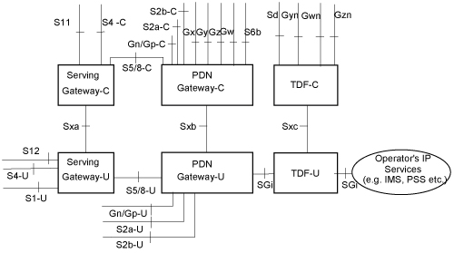
3GPP release 14 introduced the concept of CUPS – Control & User Plane Separation, and the Sx interface, this allows the control plane (GTP-C) functionality and the user plane (GTP-U) functionality to be separated, and run in a distributed fashion, allowing the node a user’s GTP-U traffic flows through to be in a different location to where the Control / Signalling traffic (GTP-C) flows.

In practice that means for an LTE EPC this means we split our P-GW and S-GW into a minimum of two network elements each.

A P-GW is split and becomes a P-GW-C that handles the P-GW Control Plane traffic (GTPv2-C) and a P-GW-U speaking GTP-U for our User Plane traffic. But the split doesn’t need to stop there, one P-GW-C could control multiple P-GW-Us, routing the user plane traffic. Sames goes for S-GW being split into S-GW-C and S-GW-U,

This would mean we could have a P-GW-U located closer to a eNB / User to reduce latency, by allowing GTP-U traffic to break out on a node closer to the user.

It also means we can scale better too, if we need to handle more data traffic, but not necessarily more control plane traffic, we can just add more P-GW-U nodes to handle this.

To manage this a new protocol was defined – PFCP – the Packet Forwarding Control Protocol. For LTE this is refereed to as the Sx reference point, it’ also reused in 5G-SA as the N4 reference point.

When a GTP-C “Create Session Request” comes into a P-GW for example from an S-GW, a PFCP “Session Establishment Request” is sent by the P-GW-C to the P-GW-U with much the same information that was in the GTP-C request, to setup the session.

So why split the Control and User Plane traffic if you’re going to just relay the GTP-C traffic in a different format?

That was my first question – the answer is that keeping the GTP-C interface ensures backward compatibility with older MMEs, PCRFs, charging systems, and allows a staged roll out and bolting on extra capacity.

GTP-C disappears entirely in 5G Standalone architecture and is replaced with the N4 interface, which uses PFCP for the Control Plan and GTP-U again.

Here’s a capture from Open5Gs core showing GTPv2C and PFCP in play.