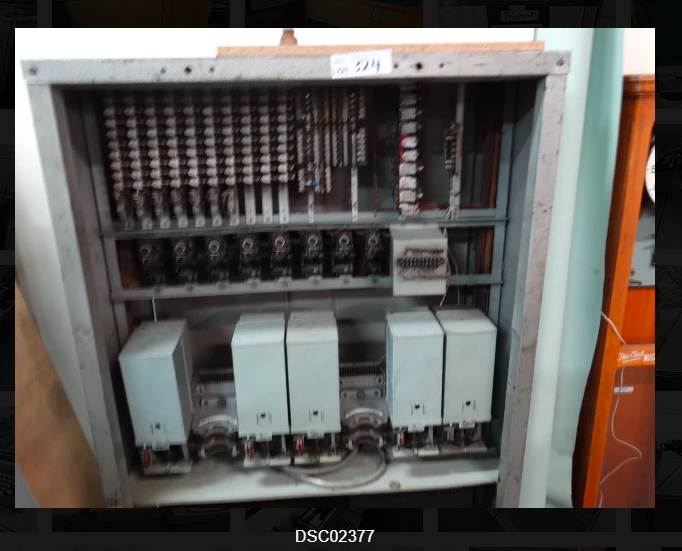
The blurry photo didn’t make anything that much clearer, but they looked like two motion switches, and being a big fan of really old telco hardware, I found myself driving to an auction selling things very much unrelated to telephone exchanges to bid on what I thought might have been a step-by-step exchange.
Photo from listing
$50 later I am now the proud owner of an Automatic Telephone & Electric Co (ATE) Liverpool works 50 line PAX (Private Automatic Exchange).
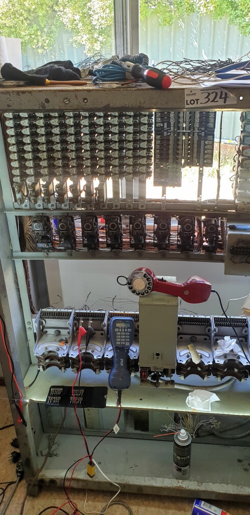
The switch
My office now has less room, a big burly battery eliminator and ring machine take up the space on my desk, but I couldn’t be happier with it.
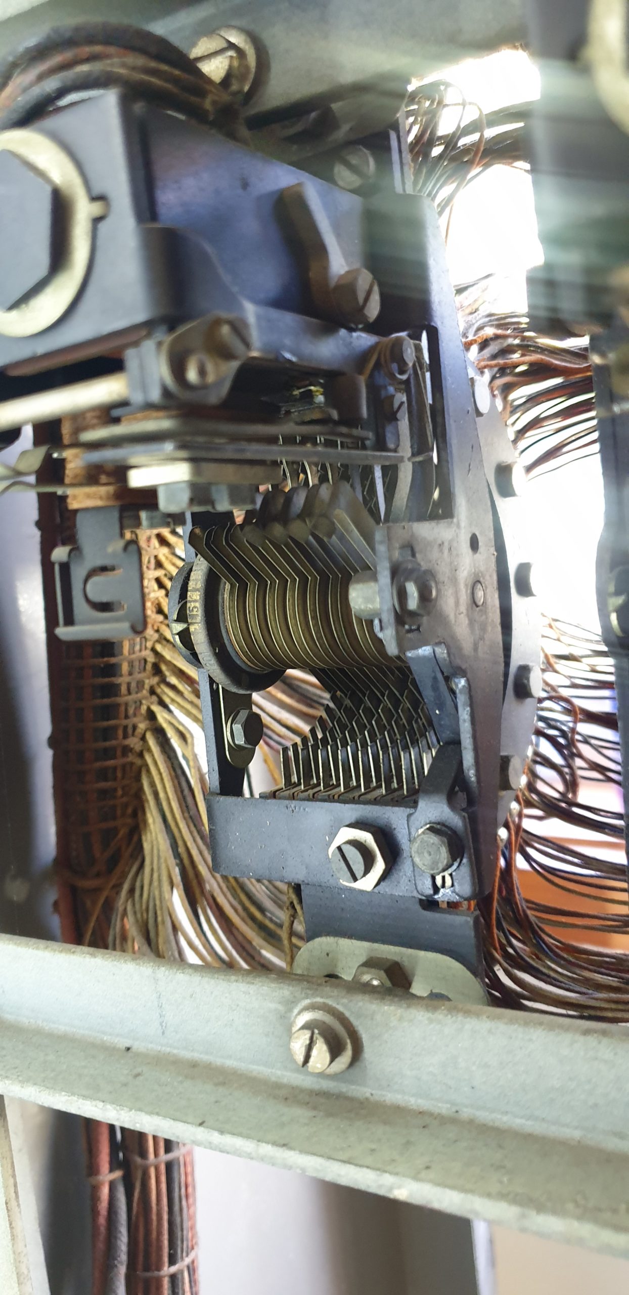
Uniselectors
Of the 5 final selectors I’ve got two somehow worked “out of the box”, while the other 3 all need some serious adjustment, but she clicks and she’s mostly complete, so should be a good summer holiday project!
I’ll post some video up when she’s fully functional.
While poking around the development and debugging features on Samsung handsets I found the ability to run IMS Debugging directly from the handset.
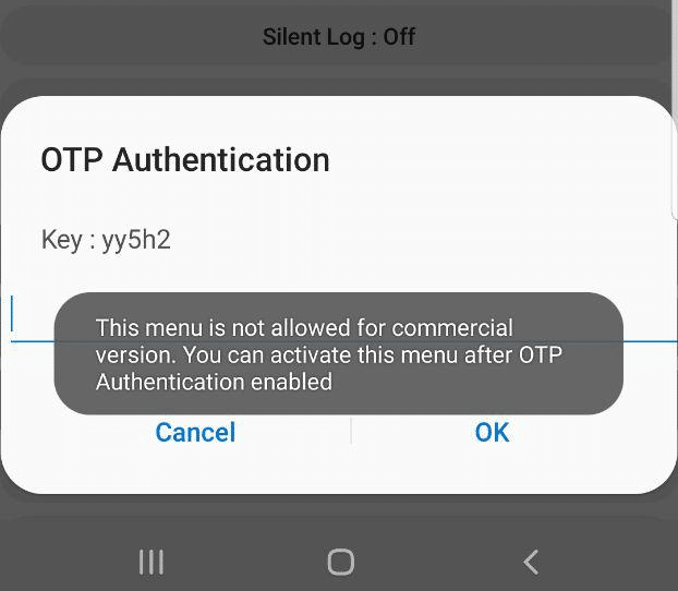
Alas, the option is only available in the commercial version, it’s just there for carriers, and requires a One Time Password to unlock.
When tapping on the option a challenge is generated with a key.
Interestingly I noticed that the key changes each time and can reject you even in aeroplane mode, suggesting the authentication happens client side.
This left me thinking – If the authentication happens client side, then the App has to know what the valid password for the key shown is…
Some research revealed you can pull APKs off an Android phone, so I downloaded a utility called “APK Extractor” from the Play store, and used it to extract the Samsung Sysdump utility.
So now I was armed with the APK on my local machine, the next step was to see if I could decompile the APK back into source code.
Some Googling found me an online APK decompiler, which I fed the compiled APK file and got back the source code.
I did some poking around inside the source code, and then I found an interesting directory:
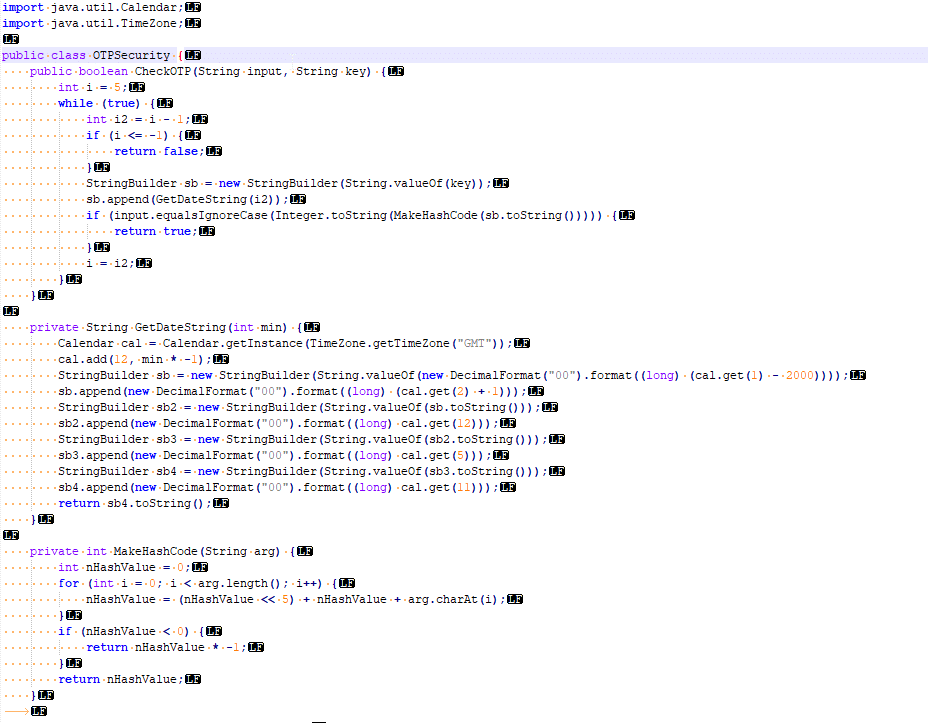
Here’s a screenshot of the vanilla code that came out of the app.
I’m not a Java expert, but even I could see the “CheckOTP” function and understand that that’s what validates the One Time Passwords.
The while loop threw me a little – until I read through the rest of the code; the “key” in the popup box is actually a text string representing the current UNIX timestamp down to the minute level. The correct password is an operation done on the “key”, however the CheckOTP function doesn’t know the challenge key, but has the current time, so generates a challenge key for each timestamp back a few minutes and a few minutes into the future.
I modified the code slightly to allow me to enter the presented “key” and get the correct password back. It’s worth noting you need to act quickly, enter the “key” and enter the response within a minute or so.
In the end I’ve posted the code on an online Java compiler,
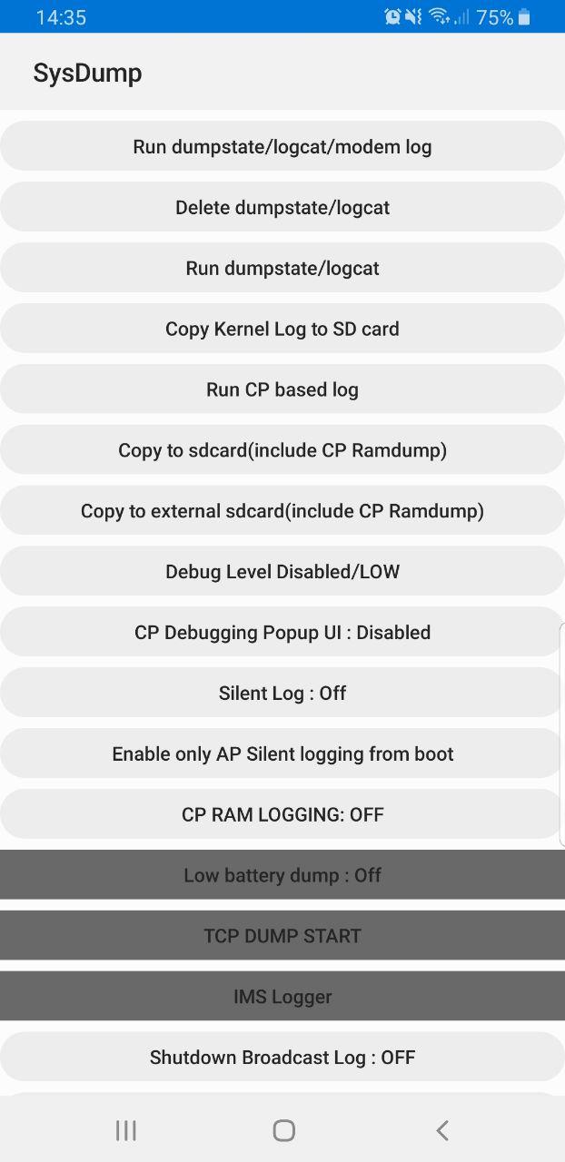
Samsung handsets have a feature built in to allow debugging from the handset, called Sysdump.
Entering *#9900# from the Dialing Screen will bring up the Sysdump App, from here you can dump logs from the device, and run a variety of debugging procedures.
But for private LTE operators, the two most interesting options are by far the TCPDUMP START option and IMS Logger, but both are grayed out.
Tapping on them asks for a one-time password and has a challenge key.
These options are not available in the commercial version of the OS and need to be unlocked with a one time key generated by a tool Samsung for unlocking engineering firmware on handsets.
Luckily this authentication happens client side, which means we can work out the password it’s expecting.
Once you’ve entered the code and successfully unlocked the IMS Debugging tool there’s a few really cool features in the hamburger menu in the top right.
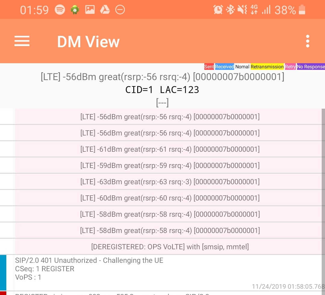
DM View
This shows the SIP / IMS Messaging and the current signal strength parameters (used to determine which RAN type to use (Ie falling back from VoLTE to UMTS / Circuit Switched when the LTE signal strength drops).
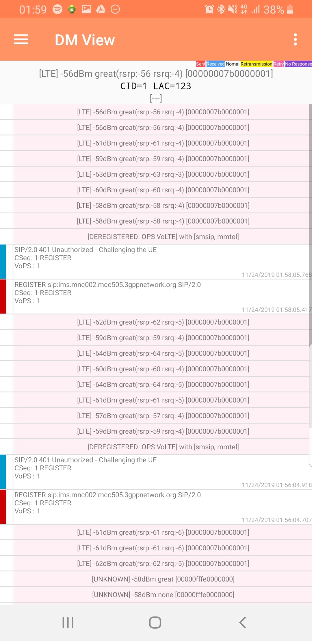
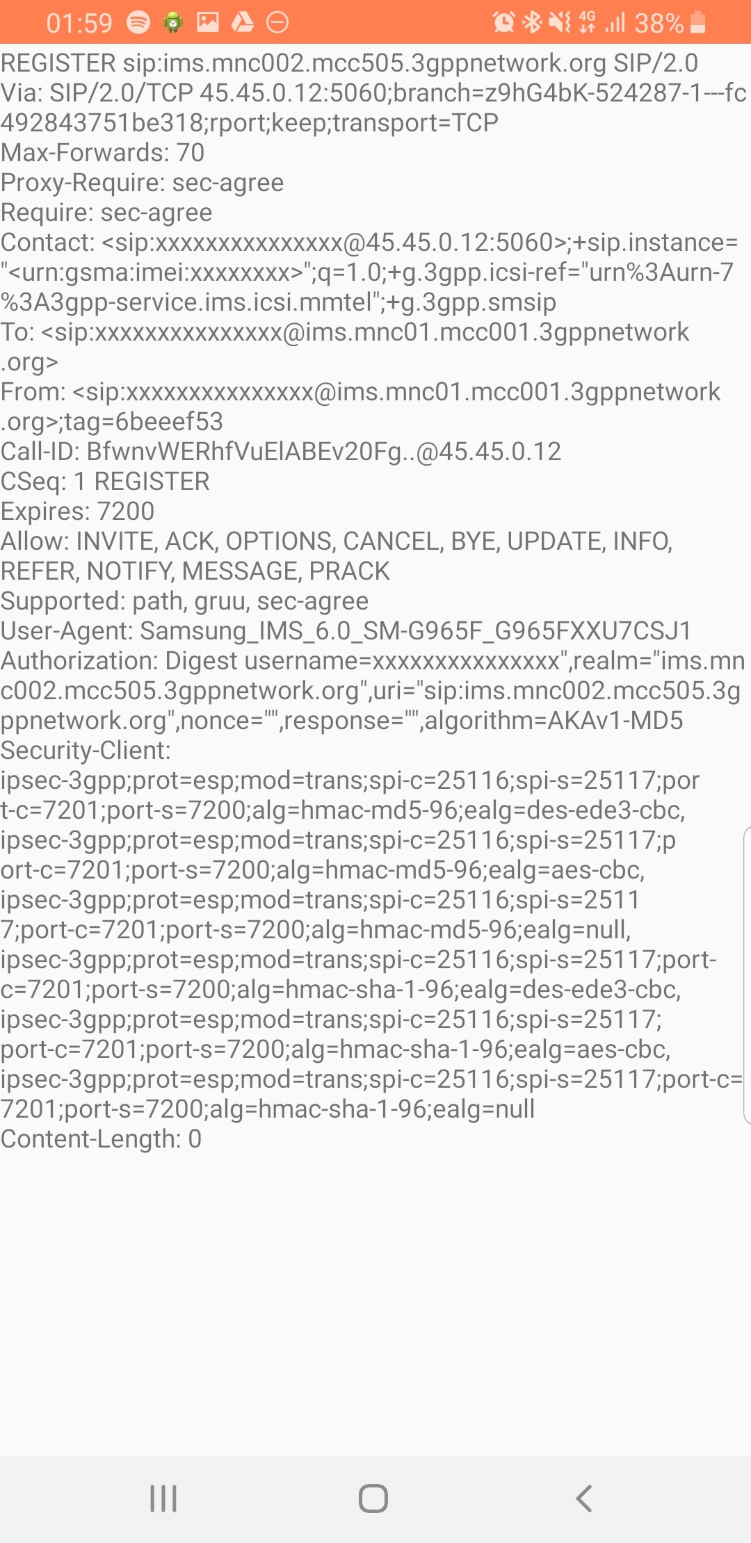
Tapping on the SIP messages expands them and allows you to see the contents of the SIP messages.
Viewing SIP Messaging directly from the handset
Interesting the actual nitty-gritty parameters in the SIP headers are missing, replaced with X for anything “private” or identifiable.
Luckily all this info can be found in the Pcap.
The DM View is great for getting a quick look at what’s going on, on the mobile device itself, without needing a PC.
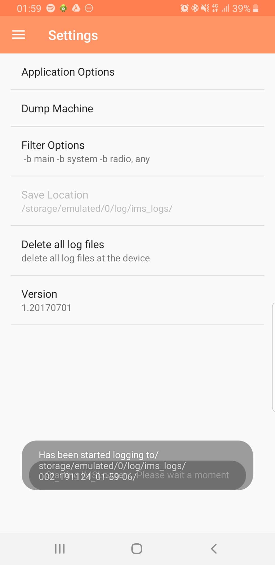
Logging
The real power comes in the logging functions,
There’s a lot of logging options, including screen recording, TCPdump (as in Packet Captures) and Syslog logging.
From the hamburger menu we can select the logging parameters we want to change.
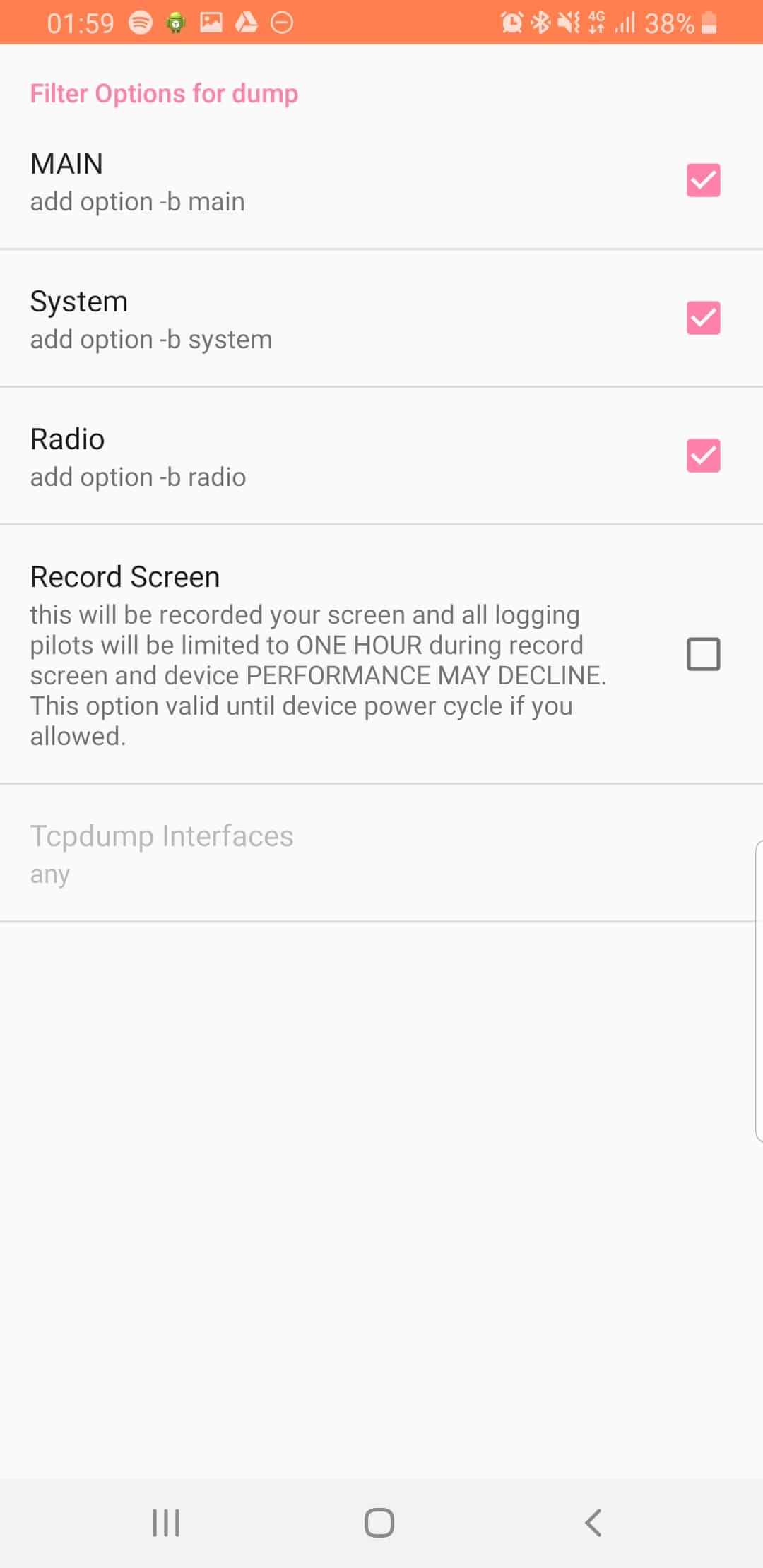
From the Filter Options menu we can set what info we’re going to log,
There’s always a lot of talk and opinion about the technologies the NBN employs, it’s effectiveness, etc.
I’ve made a conscious decision to steer clear of opinion in this blog, but there’s often talk and blame shifting between NBNco and RSPs, so I thought I’d cover how the business model works.
Because of this I thought it’d be interesting to write about how the network actually works between carriers (RSPs) and NBNco.
Physical Structure
Last Mile
The last mile in US terms, CAN in Australian Telecom lingo, is connecting the subscriber edge to the network.
NBNCo employs a few different technologies for this, depending on a number of factors;
Fiber to the Premises (Original standard – End to end fibre)
All these last mile services get consolidated and eventually end up at a local PoI – Point of Interconnect, (typically called a POP if you’re any other telco).
These are typically hosted inside exchanges, but not every exchange is an NBNco PoI, if it’s not it uses NBN Backhaul to get to the nearest PoI.
NBNco currently operates 121 PoI sites.
NBNco don’t exclusively use TEBA sites, some are hosted in NBNco “Depots”, there’s currently 10 sites not in TEBA footprints.
At the PoI
Retail Service Providers (RSPs) have to have racks inside the PoI locations, and essentially setup layer 2 cross-connects to the NBNco racks.
Once the traffic is on the RSP network, it’s the RSP’s responsibility to carry it where it needs to go, via their own network / backhaul.
Billing and Metering
Of course, if NBNco is handing off the pipes of customer traffic off to each RSP they need a way to charge the RSPs for this, this is handled by two elements – CVCs equating to the bandwidth at the PoI and AVCs equating to a fixed standing charge per connection monthly.
CVC – Connectivity Virtual Circuit
At the PoI the connection between the NBNco rack and the RSP rack is metered over a CVC – Connectivity Virtual Circuit.
This is shared across all users of that RSP at that PoI.
Let’s say I’m an RSP and I’ve purchased a 1Mbps CVC shared across my 1,000 customers at that PoI, the customers aren’t going to have a good experience.
Of course, CVC bandwidth isn’t free, previously NBNco charged on average $15.25/Mbps.
This had the effect of ensuring each RSP had just enough CVC bandwidth for their customers, but this led to some customers having a poor experience on switching to NBNco as they found their speeds dropped due to not enough CVC bandwidth at the PoI for that RSP.
In June 2017 NBNco announced a change to the pricing structure to try and encourage RSPs to buy more CVC bandwidth to ensure customers speeds weren’t bottlenecked at the CVC.
The new pricing structure makes it more financially attractive to buy more CVC bandwidth based on how many active connections (AVCs) an RSP has in place.
NBNco now charges $17.50 per symmetrical Mbps for each traffic class. (More on traffic classes later)
This means at each PoI the RSP must have a pool of CVC bandwidth large enough to meet the needs of all the customers connections (AVCs) bandwidth needs at that PoI.
AVC – Access Virtual Circuit
NBNco charges AVC fees based on the speed tier the end user will have and the traffic class (QoS) the service has applied.
(This speed tier is regardless of if the RSP has the CVC bandwidth to support this)
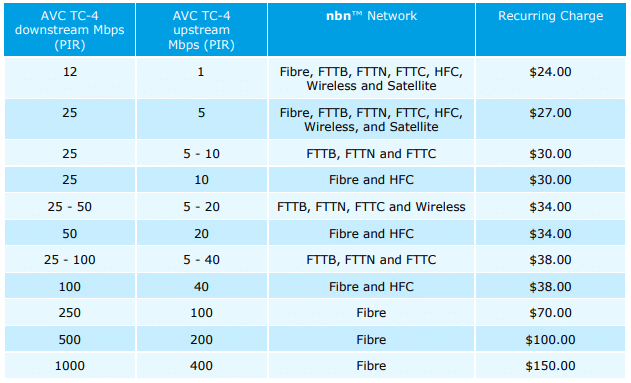
Pricing of TC4 (Best Effort) AVCs
Introducing NNIs
NBNco acknolged in Jul 2018 that for some carriers (RSPs) having presence in 121 sites puts up a large barrier to entry.
To counteract this they introduced Network-Network Interface (NNI).
Imagine you’re operating an RSP with a footprint in capital cities and PoI / CVCs in populated areas, you can’t serve customers in remote areas without having a presence at their local NBNco PoI location and buying CVC bandwidth for that location – It just wouldn’t stack up financially.
NBNco introduced the NNI product to essentially backhaul the traffic from these customers to the nearest PoI their RSP is at and share the CVC bandwidth at that PoI.
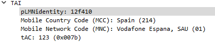
The PLMN Identifier is used to identify the radio networks in use, it’s made up of the MCC – Mobile Country Code and MNC – Mobile Network Code.
But sadly it’s not as simple as just concatenating MCC and MNC like in the IMSI, there’s a bit more to it.
In the example above the Tracking Area Identity includes the PLMN Identity, and Wireshark has been kind enough to split it out into MCC and MNC, but how does it get that from the value 12f410?
This one took me longer to work out than I’d like to admit, and saw me looking through the GSM spec, but here goes:
PLMN Contents: Mobile Country Code (MCC) followed by the Mobile Network Code (MNC). Coding: according to TS GSM 04.08 [14].
If storage for fewer than the maximum possible number n is required, the excess bytes shall be set to ‘FF’. For instance, using 246 for the MCC and 81 for the MNC and if this is the first and only PLMN, the contents reads as follows: Bytes 1-3: ’42’ ‘F6′ ’18’ Bytes 4-6: ‘FF’ ‘FF’ ‘FF’ etc.
TS GSM 04.08 [14].
Making sense to you now? Me neither.
Here’s the Python code I wrote to encode MCC and MNCs to PLMN Identifiers and to decode PLMN into MCC and MNC, and then we’ll talk about what’s happening:
In the above example I take MCC 505 (Australia) and MCC 93 and generate the PLMN ID 05f539.
The first step in decoding is to take the first two bits (in our case 05 and reverse them – 50, then we take the third and fourth bits (f5) and reverse them too, and strip the letter f, now we have just 5. We join that with what we had earlier and there’s our MCC – 505.
Next we get our MNC, for this we take bytes 5 & 6 (39) and reverse them, and there’s our MNC – 93.
Together we’ve got MCC 505 and MNC 93.
The one answer I’m still looking for; why not just encode 50593? What is gained by encoding it as 05f539?
After a few quiet months I’m excited to say I’ve pushed through some improvements recently to PyHSS and it’s growing into a more usable HSS platform.
MongoDB Backend
This has a few obvious advantages – More salable, etc, but also opens up the ability to customize more of the subscriber parameters, like GBR bearers, etc, that simple flat text files just wouldn’t support, as well as the obvious issues with threading and writing to and from text files at scale.
Knock knock.
Race condition.
Who’s there?
— Threading Joke.
For now I’m using the Open5GS MongoDB schema, so the Open5Gs web UI can be used for administering the system and adding subscribers.
The CSV / text file backend is still there and still works, the MongoDB backend is only used if you enable it in the YAML file.
The documentation for setting this up is in the readme.
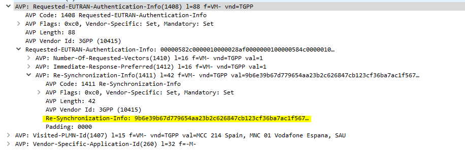
SQN Resync
If you’re working across multiple different HSS’ or perhaps messing with some crypto stuff on your USIM, there’s a chance you’ll get the SQN (The Sequence Number) on the USIM out of sync with what’s on the HSS.
This manifests itself as an Update Location Request being sent from the UE in response to an Authentication Information Answer and coming back with a Re-Syncronization-Info AVP in the Authentication Info AVP. I’ll talk more about how this works in another post, but in short PyHSS now looks at this value and uses it combined with the original RAND value sent in the Authentication Information Answer, to find the correct SQN value and update whichever database backend you’re using accordingly, and then send another Authentication Information Answer with authentication vectors with the correct SQN.
SQN Resync is something that’s really cryptographically difficult to implement / confusing, hence this taking so long.
What’s next? – IMS / Multimedia Auth
The next feature that’s coming soon is the Multimedia Authentication Request / Answer to allow CSCFs to query for IMS Registration and manage the Cx and Dx interfaces.
Code for this is already in place but failing some tests, not sure if that’s to do with the MAA response or something on my CSCFs,
LTE has great concepts like NAS that abstract the actual transport layers, so the NAS packet is generated by the UE and then read by the MME.
One thing that’s a real headache about private LTE is the authentication side of things. You’ll probably bash your head against a SIM programmer for some time.
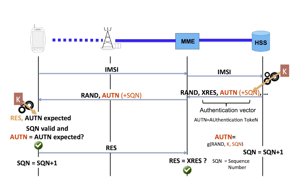
As your probably know when connecting to a network, the UE shares it’s IMSI / TIMSI with the network, and the MME requests authentication information from the HSS using the Authentication Information Request over Diameter.
The HSS then returns a random value (RAND), expected result (XRES), authentication token (AUTN) and a KASME for generating further keys,
The RAND and AUTN values are sent to the UE, the USIM in the UE calculates the RES (result) and sends it back to the MME. If the RES value received by the MME is equal to the expected RES (XRES) then the subscriber is mutually authenticated.
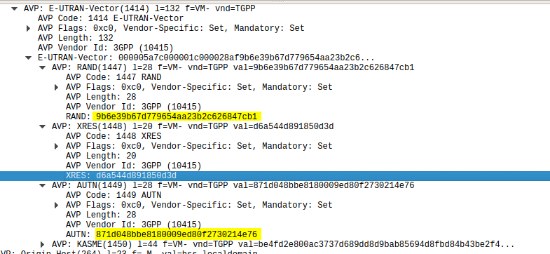
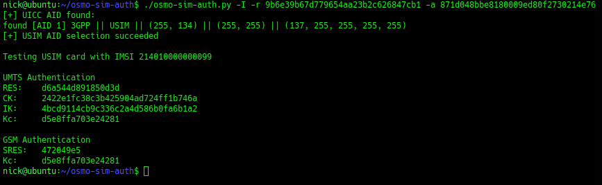
Using this tool I was able to plug a USIM into my USIM reader, using the Diameter client built into PyHSS I was able to ask for Authentication vectors for a UE using the Authentication Information Request to the HSS and was sent back the Authentication Information Answer containing the RAND and AUTN values, as well as the XRES value.
Diameter – Authentication Information Response showing E-UTRAN Vectors
Then I used the osmo-sim-auth app to query the RES and RAND values against the USIM.
The RES I got back matched the XRES, meaning the HSS and the USIM are in sync (SQNs match) and they mutually authenticated.
I thought I’d expand a little on how the Crypto side of things works in LTE & NR (also known as 4G & 5G).
Authentication primarily happens in two places, one at each end of the network, the Home Subscriber Server and in the USIM card. Let’s take a look at each of them.
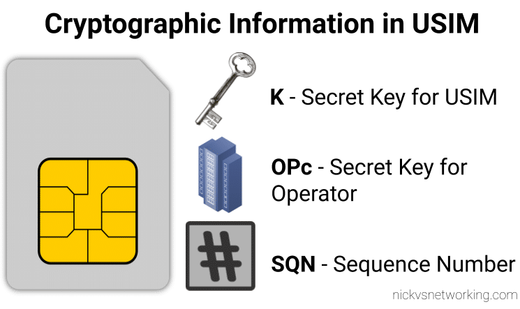
On the USIM
On the USIM we’ve got two values that are entered in when the USIM is provisioned, the K key – Our secret key, and an OPc key (operator key).
These two keys are the basis of all the cryptography that goes on, so should never be divulged.
The only other place to have these two keys in the HSS, which associates each K key and OPc key combination with an IMSI.
The USIM also stores the SQN a sequence number, this is used to prevent replay attacks and is incremented after each authentication challenge, starting at 1 for the first authentication challenge and counting up from there.
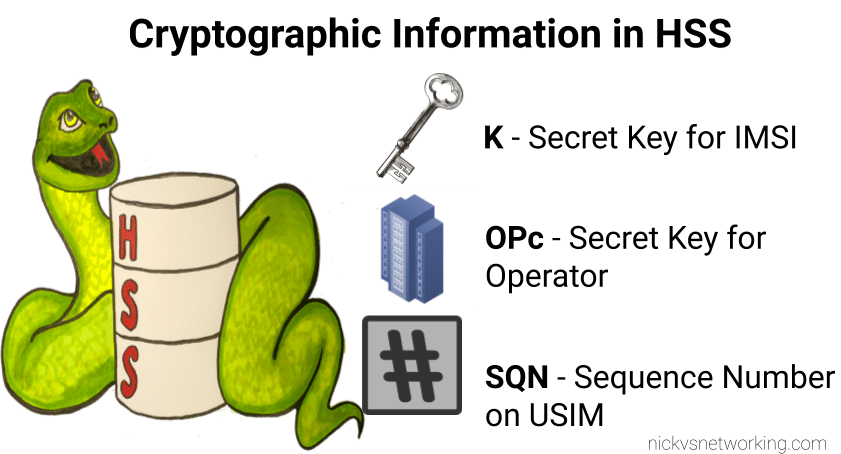
On the HSS
On the HSS we have the K key (Secret key), OPc key (Operator key) and SQN (Sequence Number) for each IMSI on our network.
Each time a IMSI authenticates itself we increment the SQN, so the value of the SQN on the HSS and on the USIM should (almost) always match.
Authentication Options
Let’s imagine we’re designing the authentication between the USIM and the Network; let’s look at some options for how we can authenticate everyone and why we use the process we use.
Failed Option 1 – Passwords in the Clear
The HSS could ask the USIM to send it’s K and OPc values, compare them to what the HSS has in place and then either accept or reject the USIM depending on if they match.
The obvious problem with this that to send this information we broadcast our supposedly secret K and OPc keys over the air, so anyone listening would get our secret values, and they’re not so secret anymore.
This is why we don’t use this method.
Failed Option 2 – Basic Crypto
So we’ve seen that sending our keys publicly, is out of the question.
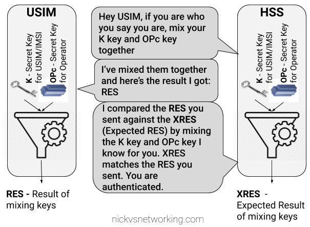
The HSS could ask the USIM to mix it’s K key and OPc key in such a way that only someone with both keys could unmix them.
This is done with some cryptographic black magic, all you need to know is it’s a one way function you enter in values and you get the same result every time with the same input, but you can’t work out the input from the result.
The HSS could then get the USIM to send back the result of mixing up both keys, mix the two keys it knows and compare them.
The HSS mixes the two keys itself, and get’s it’s own result called XRES (Expected Result). If the RES (result) of mixing up the keys by the USIM is matches the result when the HSS mixes the keys in the same way (XRES (Expected Result)), the user is authenticated.
The result of mixing the keys by the USIM is called RES (Result), while the result of the HSS mixing the keys is called XRES (Expected Result).
This is abetter solution but has some limitations, because our special mixing of keys gets the same RES each time we put in our OPc and K keys each time a subscriber authenticates to the network the RES (result) of mixing the keys is going to be the same.
This is vulnerable to replay attacks. An attacker don’t need to know the two secret keys (K & OPc) that went into creating the RES (resulting output) , the attacker would just need to know the result of RES, which is sent over the air for anyone to hear. If the attacker sends the same RES they could still authenticate.
This is why we don’t use this method.
Failed Option 3 – Mix keys & add Random
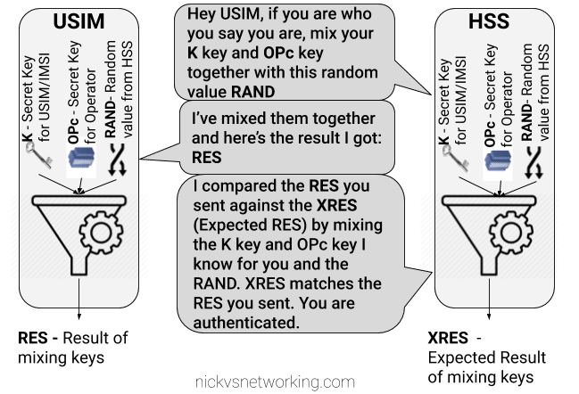
To prevent these replay attacks we add an element of randomness, so the HSS generates a random string of garbage called RAND, and sends it to the USIM.
The USIM then mixes RAND (the random string) the K key and OPc key and sends back the RES (Result).
Because we introduced a RAND value, every time the RAND is different the RES is different. This prevents against the replay attacks we were vulnerable to in our last example.
If the result the USIM calculated with the K key, OPc key and random data is the same as the USIM calculated with the same K key, OPc key and same random data, the user is authenticated.
While an attacker could reply with the same RES, the random data (RAND) will change each time the user authenticates, meaning that response will be invalid.
While an attacker could reply with the same RES, the random data (RAND) will change each time the user authenticates, meaning that response will be invalid.
The problem here is now the network has authenticated the USIM, the USIM hasn’t actually verified it’s talking to the real network.
This is why we don’t use this method.
GSM authentication worked like this, but in a GSM network you could setup your HLR (The GSM version of a HSS) to allow in every subscriber regardless of what the value of RES they sent back was, meaning it didn’t look at the keys at all, this meant attackers could setup fake base stations to capture users.
Option 4 – Mutual Authentication (Real World*)
So from the previous options we’ve learned:
Our network needs to authenticate our subscribers, in a way that can’t be spoofed / replayed so we know who to bill & where to route traffic.
Our subscribers need to authenticate the network so they know they can trust it to carry their traffic.
So our USIM needs to authenticate the network, in the same way the network authenticates the USIM.
To do this we introduce a new key for network authentication, called AUTN.
The AUTN key is generated by the HSS by mixing the secret keys and RAND values together, but in a different way to how we mix the keys to get RES. (Otherwise we’d get the same key).
This AUTN key is sent to the USIM along with the RAND value. The USIM runs the same mixing on it’s private keys and RAND the HSS did to generate the AUTN , except this is the USIM generated – An Expected AUTN key (XAUTN). The USIM compares XAUTN and AUTN to make sure they match. If they do, the USIM then knows the network knows their secret keys.
The USIM then does the same mixing it did in the previous option to generate the RES key and send it back.
The network has now authenticated the subscriber (HSS has authenticated the USIM via RES key) and the subscriber has authenticated the USIM (USIM authenticates HSS via AUTN key).
*This is a slightly simplified version of how EUTRAN / LTE authentication works between the HSS and the USIM – In reality there are a few extra values, such as SQN to take into consideration and the USIM talks to to the MME not the HSS directly.
I’ll do a follow up post covering the more nitty-gritty elements, AMF and SQN fields, OP vs OPc keys, SQN Resync, how this information is transfered in the Authentication Information Answer and how KASME keys are used / distributed.
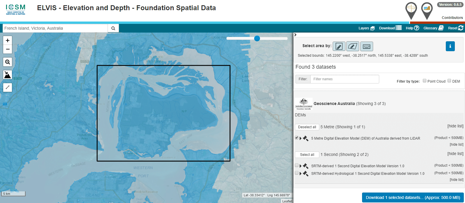
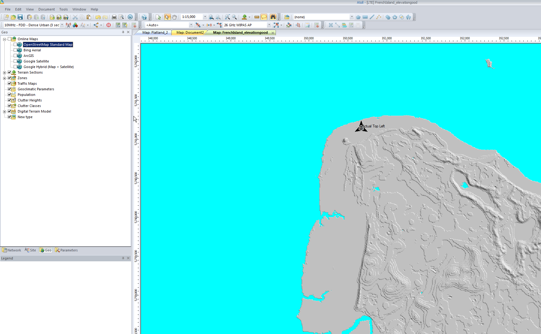
The Australian Government publishes elevation data online that’s freely available for anyone to use. There’s a catch – If you’re using Forsk Atoll, it won’t import without a fair bit of monkeying around with the data…
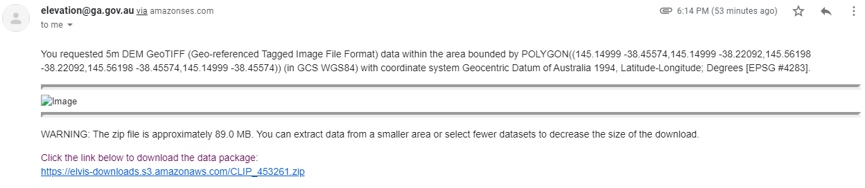
You draw around the area you want to download, enter your email address and you’re linked to a download of the dataset you’ve selected.
So now we download the data from the link, unzip it and we’re provided with a .tiff image with the elevation data in the pixel colour and geocoded with the positional information.
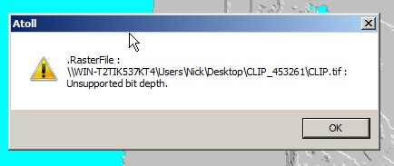
Problem is, this won’t import into Atoll – Unsupported depth.
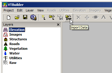
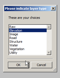
I fired it up, and imported the elevation tiff file we’d downloaded.
Selected “Elevation” waited a few seconds and presto!
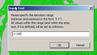
We can export from here in the PNG 16 bit grayscale format Atoll takes, but there’s a catch, negative elevation values and blank data will show up as giant spikes which will totally mess with your propagation modeling.
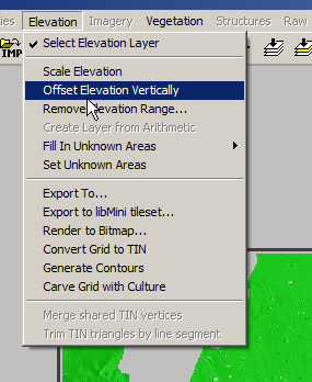
So I found an option to remove elevation data from a set range, but it won’t deal with negative values…
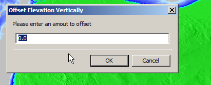
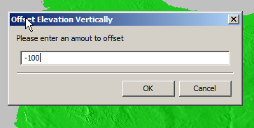
So I found another option in the elevation menu to offset elevation vertically, I added 100 ft (It’s all in ft for some reason) to everything which meant my elevation data that was previously negative was now just under 100.
So if an area was -1ft before it was now 99ft.
Now I was able to use the remove range for anything from 0 100 ft (previously sea level)
Now my map only shows data above sea level
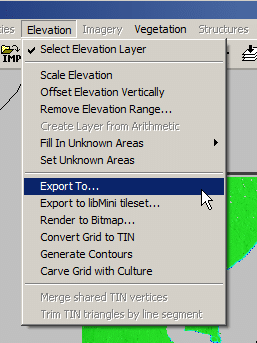
Now I offset the elevation vertically again and remove 100ft so we get back to real values
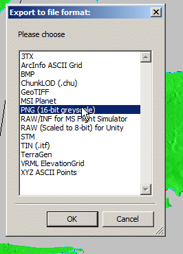
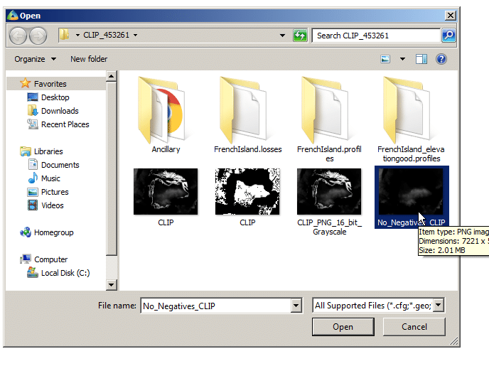
Now I was able to export the elevation data from the Elevation -> Export to menu
Atoll seems to like PNG 16 bit greyscale so that’s what we’ll feed it.
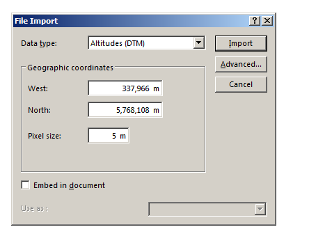
In Atoll we’ll select File -> Import and open the PNG we just generated.
Data type will be Altitude, Pixel size is 5m (as denoted in email / dataset metadata).
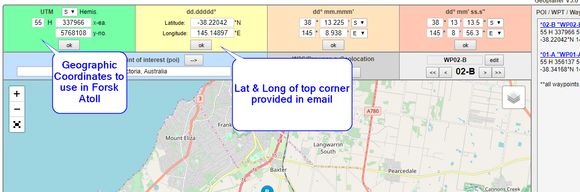
Next question is offset, which took me a while to work out…
The email has the Lat & Long but Atoll deals in WGS co-ordinates,
Luckily the GeoPlanner website allows you to enter the lat & long of the top corner and get the equivalent West and North values for the UTM dataum.
Enter these values as your coordinates and you’re sorted.
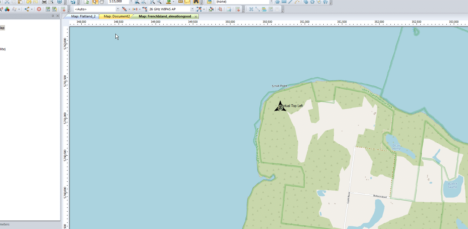
I can even able a Map layer and confirm it lines up:
Let’s take a look at GTP, the workhorse of mobile user plane packet data.
This post covers all generations of mobile data (2.5 -> 5G), so I’m using generic terms.
GSM, UMTS, LTE & NR all have one protocol in common – GTP – The GPRS Tunneling Protocol.
So why do every generation of mobile data networks from GSM/GPRS in 2000, to 5G NR Standalone in 2020, rely on this one protocol for transporting user data?
So Why GTP?
GTP – the GPRS Tunnelling Protocol, is what encapsulates and tunnels IP packets from the internet / packet data network, to and from the User.
So why encapsulate the packets? What if the Base Station had access to the internet and routed the traffic to the users?
Let’s say we did that, we’d have to have large pools of IP addresses available at each Base Station and when a user connected they’d be assigned an IP Address and traffic for these users would be routed to the Base Station which would forward it onto the user.
This would work well until a user moves from one Base Station to another, when they’d have to get a new IP Address allocated.
TCP/IP was never designed to be mobile, an IP address only exists in a single location.
Breaking out traffic directly from a base station would have other issues, such as no easy way to enforce QoS or traffic policies, meter usage, etc.
How to fix IP’s lack of mobility? GTP.
GTP addressed the mobility issue by having a single fixed point the IP Address is assigned to (In GSM/GRPS/UMTS this is the Gateway GPRS Support Node, in LTE this is the P-GW and in 5G-SA this is the UPF), which encapsulates IP traffic to/from a mobile user into GTP Packet.
You can think of GTP like GRE or any of the other common encapsulation protocols, wrapping up the IP packets into a GTP packet which we can rerouted to different Base Stations as the users move from being served by one Base Station to another.
This easy redirecting / rerouting of user traffic is why GTP is used for NR (5G), LTE (4G), UMTS (3G) & GPRS (2.5G) architectures.
GTP Packets
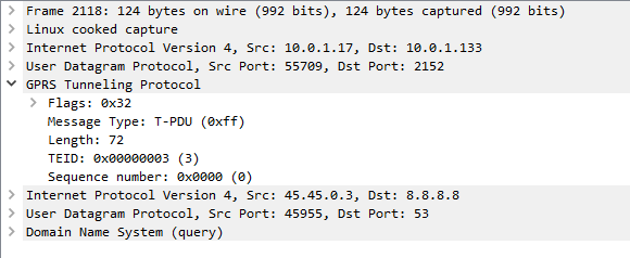
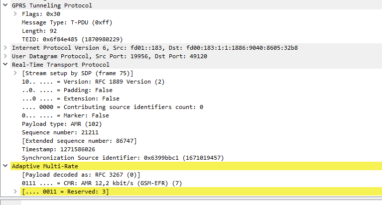
When looking at a GTP packet of user data you’d be forgiven for thinking nothing much goes on,
Example GTP packet containing a DNS query
Like in most tunneling / encapsulation protocols we’ve got the original network / protocol stack of IPv4 and UDP, and a payload of a GTP packet.
The packet itself is pretty bare bones, there’s flags, denoting a few basics like version number, the message type (T-PDU), the length of the GTP packet and it’s payload (used for delineating the end of the payload), a sequence number an a Tunnel Endpoint Identifier (TEID).
In the payload, we can see the network / protocol stack and application layer of the contents of the GTP packet.
From a mobility standpoint, the beauty of GTP is that it takes IP packets and puts them into a media stream of sorts, with out of band signalling, this means we can change the parameters of our GTP stream easily without touching the encapsulated IP Packet.
When a UE moves from one base station to another, all that has to happen is the destination the GTP packets are sent to is changed from the old base station to the new base station. This is signalled using GTP-C in GPRS/UMTS, GTPv2-C in LTE and HTTP in 5G-SA.
Traffic to and from the UE would look the same as the screenshot above, the only difference would be the first IPv4 address would be different, but the IPv4 address in the GTP tunnel would be the same.
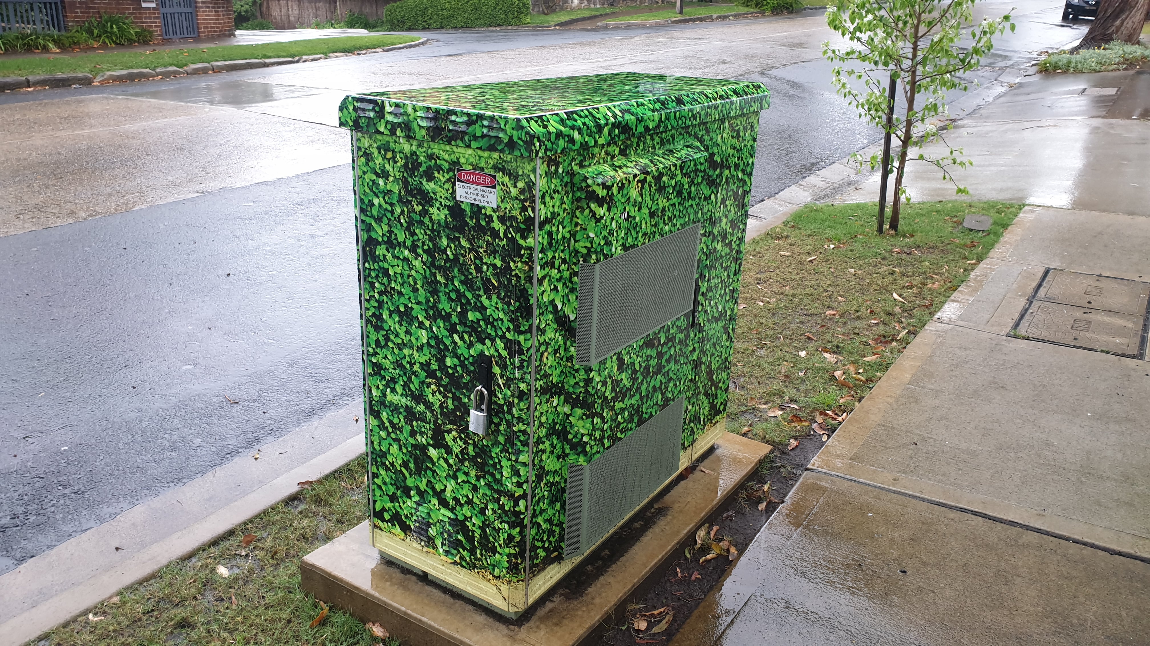
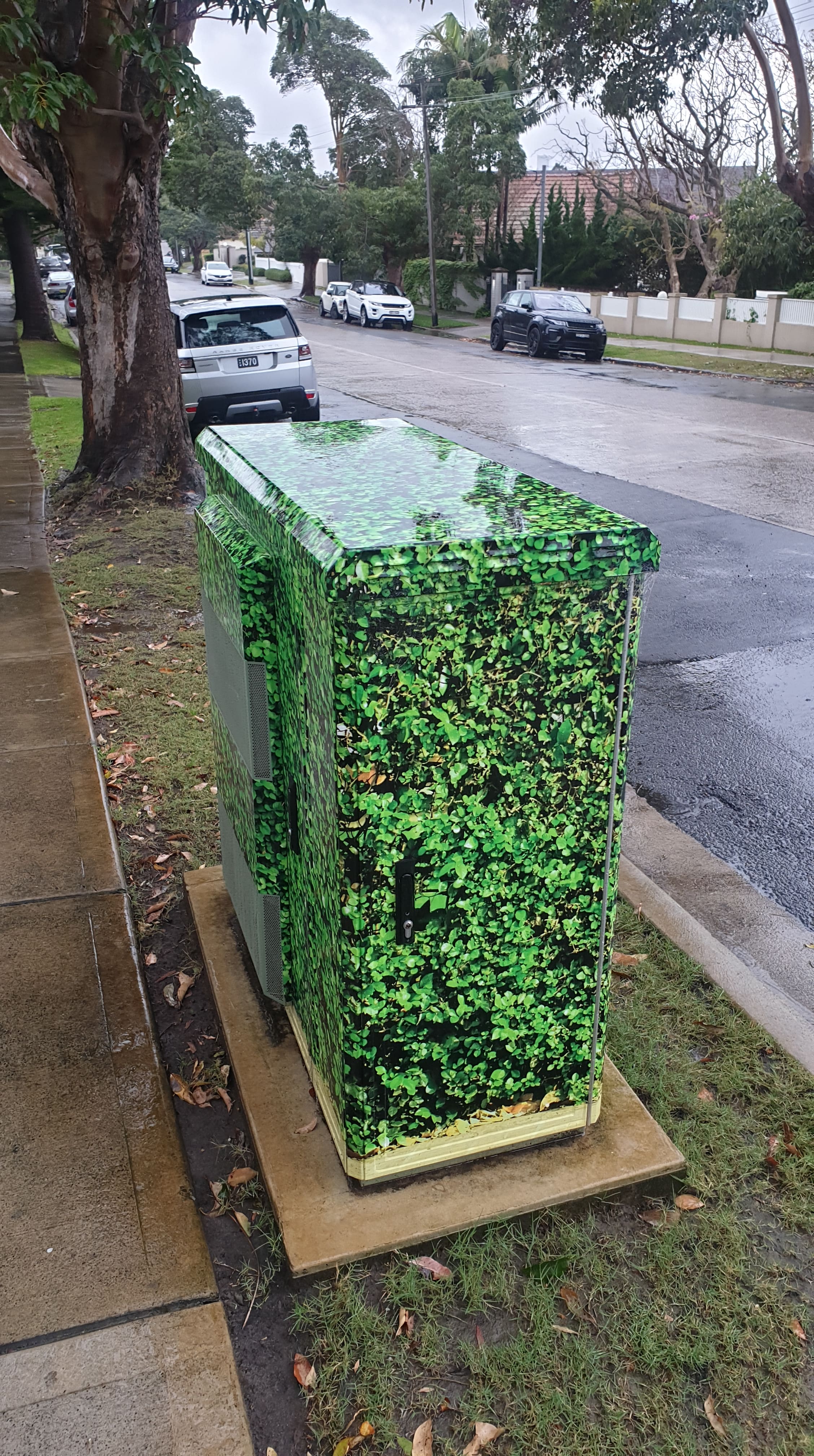
NBNco’s FTTC technology is accounting for a larger and larger share of the access network mix as the rollout nears completion, but let’s take a look at the hardware doing the heavy lifting.
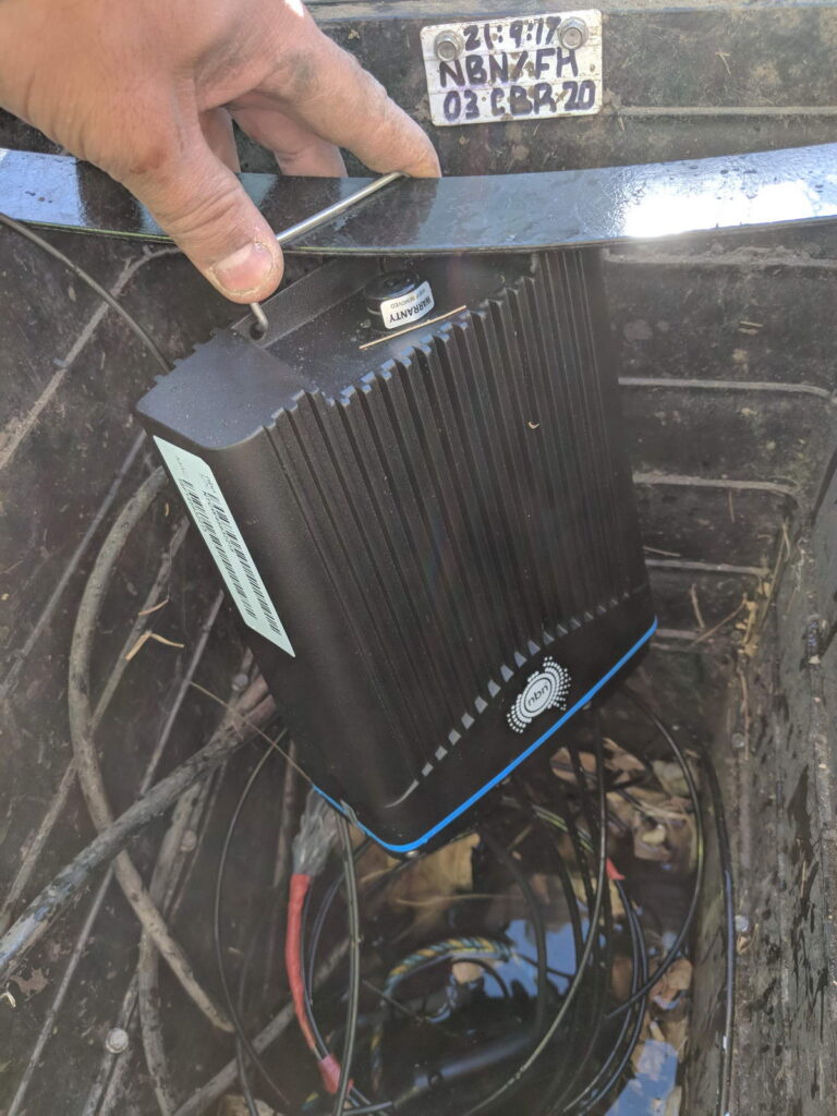
I won’t go into the fiber network build NBNco are using (Squids, etc) in this post, we’ll just focus on the DSLAM that lives in the pit outside your house, or in NBN parlance – DPU or Distribution Point Unit.
In short, this is a 4 port DSLAM, fed by a fiber service and reverse powered.
The unit itself is waterproof, allowing it to live in the pit outside a customer premises, for FTTC deployments it’s common for every second P3 pit to contain a DPU (each pit typically feeds two premises).
There’s 4 copper tails for connecting in each of the 4 copper pairs to feed 4 premises. The copper run is typically less than 100m and is pretty easy to work out – Pace the distance from your first telephone outlet (TO) to your nearest pit, and there’s a 50% chance that’s the length of your cable run. Because of the short run of cable it’s a lot less to go wrong in the CAN, the only joint on the pair being the one on the DPU itself and anything inside the demarcac.
The DPU is powered by the customer’s modem via a reverse power feed, this means NBNco don’t have to worry about powering the unit, something on FTTN cabinets has been a maintenance headache due to battery backup maintenance.
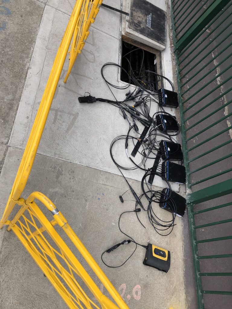
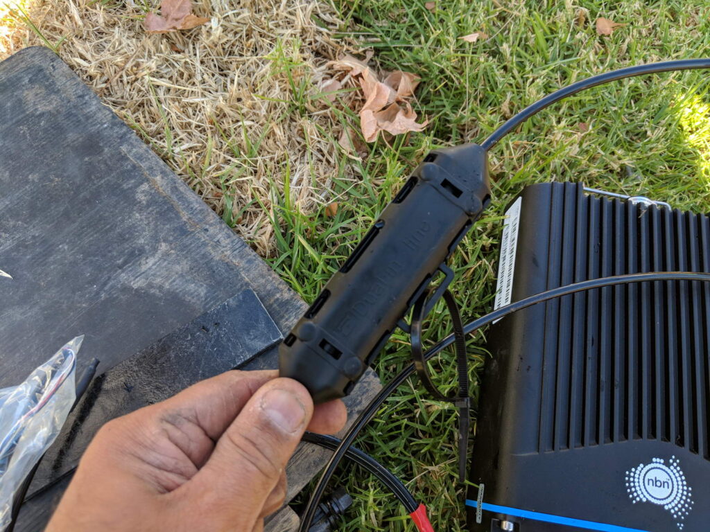
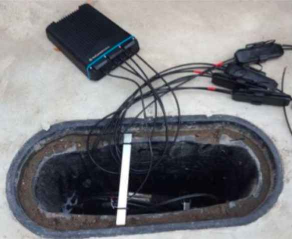
The lead in cable to the customer premises is joined to the DPU via a “Snot Box”.
Snot box for joining lead in to DPUDPU in the pit
Unfortunately due to the enclosures being water tight and sealed, they don’t have the best thermal management. It’s not uncommon for them to reach 50+ degrees C in the field, which leads to a high failure rate, especially during summer.
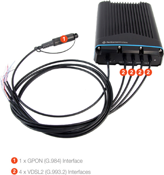
NetComm Wireless / Casa NDD-4100
In 2016 NetComm Wireless (Now owned by Casa Systems) signed an agreement with NBNco to provide Fiber to the Distribution Point (FTTdp) Distribution Point Unit (DPU) equipment to NBNco for the launch in 2018, using their NetComm NDD-4100 units.
The unit has 4 ports for customer connections over a VDSL G.9923 interface, with reverse power feed, meaning the unit is fed by the CPE.
For backhaul the unit has GPON G.984 interface.
The device may not be powered at all times so a management proxy caches commands that are fed to the system when it comes back online.
Promo video
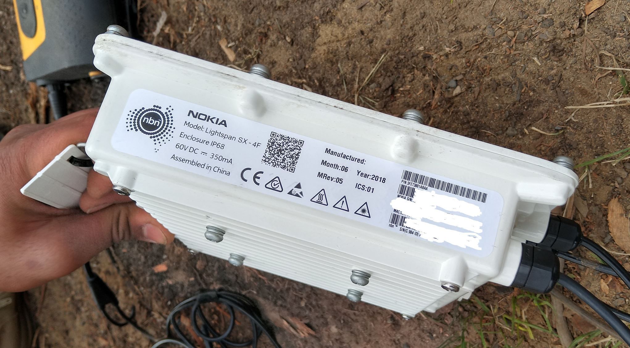
Nokia lightspan sx-f
In June 2018 NBNco started trialing Nokia DPUs, and many later installations since then are using the Nokia DPU.
I’ve head a bunch of complains about the NetComm having issues and dying, and for a sealed unit there’s very little debugging that can be done to it.
In the Melbourne office of NBNco there’s a Nokia DPU that’s been running in a fish tank for a number of years.
I started working on a private LTE project a while ago; RAN hardware (eNodeBs) were on the way, down to a shortlist of a few EPC platforms, but I still needed USIMs before anyone was connecting to the network.
So why are custom USIMs a requirement? Can’t you just use any old USIM/SIMs?
For roaming to work between carriers they’ve got to have their HSS / DRA connecting to the DRA or HSS of other carriers, to allow roaming subscribers to access the network, otherwise they too would fall foul of the mutual network authentication and the USIM wouldn’t connect to the network.
The first USIMs I purchased online through a popular online marketplace with a focus on connecting you to Chinese manufacturers. They listed a package of USIMS, a USB reader/writer that supported all the standard USIM form factors and the software to program it, which I purchased.
The USIMs worked fairly well – They are programmable via a card reader and software that, although poorly translated/documented, worked fairly well.
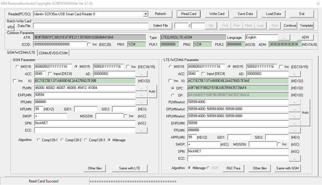
USIM Programming Interface
K and OP/OPc values could be written to the card but not read, while the other values could be read and written from the software, the software also has the ability to sequentially program the USIMs to make bulk operations easier. The pricing worked out about $8 USD per USIM, which although expensive for the quantity and programmable element is pretty reasonable.
Every now and then the Crypto values for some reason or another wouldn’t get updated, which is exactly as irritating as it sounds.
Pretty quickly into the build I learned the USIMs didn’t include an ISIM service on the card, ISIM being the service that runs on the UCCID responsible for IMS / VoLTE authentication.
Again I went looking and reached out to a few manufacturers of USIMs.
The big vendors, Gemalto, Kona, etc, weren’t interested in providing USIMs in quantities less than 100,000 and their USIMs came from the factory pre-programmed, meaning the values could only be changed through remote SIM provisioning, a form of black magic.
In the end I reached out to an OEM manufacturer from China who provided programmable USIM / ISIMs for less than I was paying on the online marketplace and at any quantity I wanted with custom printing options, allocated ICCIDs, etc.
The non-programmable USIMs worked out less than $0.40 USD each in larger quantities, and programmable USIM/ISIMs for about $5 USD.
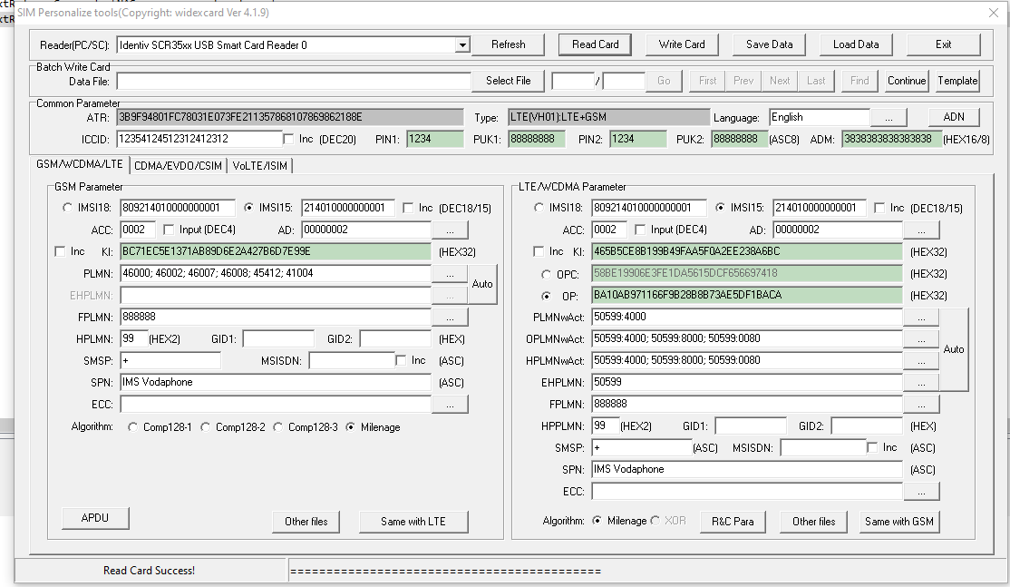
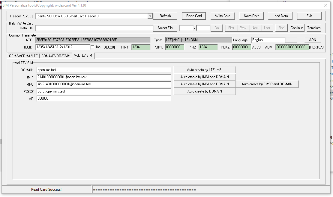
The software was almost identical except for the additional tab for ISIM operations.
USIM / ISIM programmingISIM parameters
Smart Card Readers
In theory this software and these USIMs could be programmed by any smart card reader.
In practice, the fact that the ISO standard smart card is the same size as a credit card, means most smart card readers won’t fit the bill.
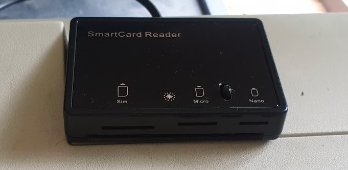
I tried a few smart card readers, from the one built into my Thinkpad, to a Bluedrive II from one of the USIM vendors, in the end the MCR3516 Smart Card Reader which reads 4FF USIMs (Standard ISO size smart card, full size SIM, Micro SIM and Nano SIM form factors, which saved on so much mucking about with form factor adapters etc.
4FF Smart Card Reader for programming SIM/USIM/ISIM
Future Projects
I’ve got some very calls “Multi Operator Neutral Host” (MoNEH) USIMs from the guys at Telet Research I’m looking forward to playing with,
eSIMs are on my to-do list too, and the supporting infrastructure, as well as Over the Air updating of USIMs.
The numbering system lists all the phone numbers in Australia and the carrier they’re assigned to (Donor Carrier when ported).
This means each carrier downloads this data from what is now ACMA (but was at the time ACA) and for each outgoing call look the number up in that data set and route to the correct carrier.
This routing is used when a number has not been ported – The CSP it’s allocated to by ACMA is the CSP to route calls to.
During Porting – Donor & Losing CSP the Same
At the time the number is ported the Losing CSP provides Donor Transit Routing – In practice this is nothing more than a fancy redirection/ forward to the new carrier.
Once the port is completed (and the Emergency Porting Return period has expired) the Losing CSP (who in this case is also the donor CSP) updates their PLNR file, to include the number that’s just been ported out and the new carrier’s code.
During Porting – Donor & Losing CSP Different (3rd Party Porting)
At the time the number is ported the Losing CSP provides Donor Transit Routing – In practice this is nothing more than a fancy redirection/ forward to the new carrier.
Once the port is completed (and the Emergency Porting Return period has expired) the Donor CSP updates their PLNR file, to update the record for the ported number, which previously showed the code of the Losing CSP and now must show the new CSP code.
After Porting – PLNR Update
After the PLNR has been updated by the Donor CPSs, other CPS that participate in porting must update their routing records to ensure they route directly to the Gaining CSP and not to the Donor CSP and rely on Donor Routing.
Donor Routing is only required to be in place for a short time, meaning carriers that don’t update their routes will find the ported destination unreachable once donor transit routing has been stopped.
Why am I still billed after a number is ported out?
The Losing CSP does not need to take any action to disconnect Customer’s Telephone Number(s).
3.4.3
This means just porting out a number from a CSP doesn’t mean billing from the Loosing CSP will stop.
Continuing contractual agreements between the customer and Loosing CSP may still be in place and the customer is responsible for requesting the services be cancelled with the Loosing CSP.
Some CSPs work out that if you’re porting out a number you don’t want their services anymore, but they’re not obliged to and most will do what they can get away with.
What is a Bilateral Peering Agreement?
While a customer is legally entitled to move a number they have full control over (As outlined in Telecommunications Numbering Plan 2015), in practice phone numbers can only be moved from one carrier to another if both CSPs have a Bilateral Peering Agreement with each other.
These agreements primarily sort out the commercials of how much they’ll pay each other per port in / out.
It’s worth also noting that the Code only defines the minimum standard and process, two CSPs that have a bilateral peering agreement in place are able to process ports faster and more efficiently than the minimum standard outlined in the code.
Carriage Service Provider vs Carrier?
I’ve been sing the term Carriage Service Provider and Carrier interchangeably.
The difference as far as the code is concerned is one is who a customer pays for the service, while the other is the provider of the service. Generally it’s safe to assume that the CSP is also the Carrier and not a re-seller.
These numbers can be ported to other CSPs (this is after all what LNP is all about) but after the number is routed to a different carrier the Donor Carrier remains the carrier listed in the Numbering Plan.
The Donor Carrier is responsible for Donor Transit Routing (A temporary redirect to numbers that have been ported away recently) for any numbers that have recently been ported out, and publishing the number and new carrier details for each number ported out in their PLNR file.
These numbers can be ported to other CSPs (this is after all what LNP is all about) but after the number is routed to a different carrier the Donor Carrier remains the carrier listed in the Numbering Plan.
In a scenario where a call needs to route to a destination where the current carrier for that destination is unknown, the call is routed to the Donor Carrier, as that’s who the number is originally allocated to by ACMA.
Upon reciept of a call by the donor carrier to a number that has been ported out, the donor’s switch finds the correct Access Service Deliver (ASD) and redirects the call to them.
This is a temporary service – CSPs are only obliged to do this for 5 days, after which it’s assumed the PLNR file of the donor will have been read by all the other CSPs and they’ll be routing the traffic to the correct CSP and not the Donor CSP.
Third Party Ports
Third Party Porting is where the Donor Carrier is neither the Losing Carrier or the Gaining Carrier. Third Party Porting requires bilateral agreements to be in place between each of the parties involved.
As we just covered ACMA allocates numbers to CSPs, when a number is ported to a different CSP the number is still allocated to the original CSP as far as ACMA and The Numbering System are concerned.
The CSP the number was originally allocated to is the Donor CSP – forever.
Let’s look at a two party port first:
A number is allocated by ACMA to CSP 1
The customer using that number decides to port the to CSP 2 using the standard LNP process
CSP 1 performs Donor Transit Routing for the required 5 days and updates it’s PLNR file to denote that the number has been ported to CSP 2
Now let’s consider a three party port, carrying on from the steps above.
The Customer decides they want to move from CSP 2 to another CSP – CSP 3
At the time of the port the donor CSP (CSP 1) must:
CSP 1 must update it’s PLNR records for this number to denote it’s no longer with CSP 2 but is now with CSP 3
CSP 1 must provide Donor Transit Routing for the required 5 business days – redirecting calls to CSP 3
So even though the number is moving from CSP 2 to CSP 3 as the number was originally allocated to CSP 1, it is, and will always be the Donor Carrier and as such has to provide Donor Transit Routing and update it’s PLNR each time the number is ported.
Port Reversal / Emergency Return
Ports have an emergency return window inside which the port can be reverted. For Cat C ports this invovles the project manager of one CSP contacting the project manager for the other CSP and requesting the return.
In the event the end customer has requested the Port Reversal / Emergency return they’re typically liable for a very hefty fee to do so.
Give Back & Quarantine of Numbers
After a number is no longer required, it’s given back to the donor carrier who places it in quarantine and typically does not reallocate the number for 6 months.
In some cases such as a wronly cancelled number the customer may be able to get a number that’s been cancelled back while it’s in it’s quarantine state, however this is not required and up to the donor carrier.
Including Customer Account Numbers when Porting
Prior to 2016, a customer moving from one CSP to another CSP were required to include their account number (“Service Account Number”) they had with the Loosing CSP to the Gaining CSP when submitting the Port which was verified against the Loosing Carrier’s records to ensure the correct Customer / Service combo.
This led to a lot of ports being rejected unnecessarily due to mismatched account numbers, as such the the requirement to include a valid matching account number with the loosing CSP has been removed.
Service Account is to remain as a mandatory field, and a standard validation but any mismatches are not to be rejected.
Where’s Cat B & Cat D?
Cat B Dropped in 2013 revision due to lack of use.
Cat D is almost the same as a Cat A port but allows services with an active ULL diversion to be ported. These are quite rare and a very specific use case.
Why is my Cat C Port taking so long?
You may find after submitting a port the date you’ve got back for porting is months away. The Loosing Carrier sets the porting date, and as they’re loosing the customer, they’re often not so keen to action the port quickly when they’re loosing the customer after all.
Lead Times are determined by the Losing Carrier. These may vary by product including variations due to the size of the product or the number of sites to which a particular service is offered.
3.5.10
Tidbit: One of Australia’s largest carriers has a 20,000 number per day limit on porting, meaning they’re only able to process up to 20,000 ports per day in or out. Once that limit is reached no more ports can be accepted for that day, so the ports are delayed until the next day, etc, etc, leading to considerable lead times.
The code requires CSPs to keep Service Metrics on porting time-frames, but there’s no penalty for being slow. (Section 3.6)
Third Party ports also take a lot longer due to the requirement to find a time window that suits all 3 carriers.
Can I arrange my numbers to be Ported after-hours?
CSPs are not required to port numbers outside of the “Standard Hours” defined in the code. (Section 3.8.1 )
However, most CSPs have included support for this inside their bilateral agreements with other carriers. This typically costs more for the customer, but also comes with the added risk of if the port fails there are fewer technical / engineering resources available at the Loosing and Gaining Carrier’s respective ends to sort it out if something goes wrong.
What’s a PNO?
Porting Notification Order – A message containing either a Simple Notification Advise (SNO) for Simple (Cat A) ports, or a Complex Notification Advise (CNA) for Complex (Cat C) ports.
Each PNO contains a unique sequential reference number to differentiate / associate the PNO with a particular porting request.
PLNR – Ported Local Number Registry
PLNR is nothing more than a giant text file, containing a list of numbers originally allocated to that CSP but that have been ported to another CSP, and with each number that’s been ported out the carrier code of the CSP it’s now with.
Information to facilitate Call Routing is provided by the Donor Carrier who is required to notify Carriers, via a Ported Local Number Register, that a Port is pending, completed or did not proceed. This relates to all Ports, including Third Party Ports. All participants must use the Ported Local Number Registers to determine the correct Call Routing.
Typically transferred via Web interface:
… a web site that contains a file with a list of Telephone Numbers that have been Ported away from the Donor, or have just returned.
PLNR data is encoded as a fixed-format text file.
What is Re-targeting?
Re-Targeting is a fancy term of changing the date & time.
It’s typically more efficient to re-target a port than withdraw it and resubmit it.
For only two re-targets are allowed for each unique SNA. (Section 4.2.9)
The Australian telecommunications industry was deregulated in 1997, meaning customers could have telecommunications services through a Carriage Service Provider (CSP) of their choice.
In order to increase competition and make it easier to move to a different CSP, the ACMA (Or as they were then the ACA) declared that Local Numbers (Geo numbers / land lines) were a “Portable Service”. This meant that if a customer didn’t like their current Carriage Service Provider (CSP) they could give them the flick (making them the Loosing Carrier), move to a new CSP (Gaining Carrier) but keep their existing phone numbers by moving them to the new carrier in a process known as Local Number Portability (LNP).
The Local Number Portability (LNP) standard was first defined by Comms Alliance in 1999 in ACIF C540 and defines the process of moving numbers between Carriage Service Providers (CSPs), however 22 years later the process can still be a baffling system for many customers, end users and carrier staff to navigate.
Acronyms galore exist and often the porting teams involved themselves aren’t 100% sure what goes on in the porting process.
In 1997 ISDN was first still an emerging technology and porting was typically a customer moving from one PSTN / POTS line provided by one CSP to another PSTN / POTS line provided by a different CSP – a simple port.
Two processes were defined, one for managing simple ports involving moving one simple number from one CSP to another CSP – Called Simple Porting or “Cat A” – which made up the majority of porting requests at the time, and another process for everything else managed by a project manager from the Loosing and Gaining CSP called Complex Porting or “Cat C“.
Simple porting, classified as “Cat A” is used for porting single simple services (numbers).
The Cat A process can only be used for moving a “simple” standalone number – with no additional features – from one carrier to another.
The typical use case for Cat A port is moving a one copper PSTN / POTS line (Active line with no Fax Duet, Line Hunt, etc) from one carrier to another – as I said before, Cat A ports made up the majority of porting requests when the system was first introduced as the vast majority of services were copper POTS lines.
The process is automated at both ends, essentially the carriers send each other the numbers to be moved (more on that later) and their switches automatically process this and begin routing the number.
These ports are typically completed within a few days to a week and the customer gets a notification when the port is completed.
Cat C / Complex Number Porting
For all number porting that don’t meet the very specific requirements of Cat A aren’t met – and sometimes even if they are met, ports are processed as Cat C ports.
Cat C ports require a project manager at both the Gaining Carrier and the Losing Carrier to agree on the details for the port and the move the numbers, each using their own internal process.
Lead times on Cat C ports are long – and getting longer, so from submitting a port to it’s completion can take 90+ days, and there is no confirmation required to the customer to let them know the services have been ported successfully.
Administrative Process of Ports (CatA & CatC)
Strap yourself in for a whirlwind of acronyms…
The Code does not constrain two or more individual industry participants agreeing to different arrangements
Section 1.3.6
Because of this it means this is the minimum standard, some CSPs have improved upon this between each other, however there’s a bit of a catch 22 in that CSPs have no incentive to make porting numbers out easier, as they’re typically losing that customer, so the process is typically not improved upon in any meaningful way that makes the customer experience easier.
Without further ado, here’s what Cat A & Cat C ports look like under the hood…
Note: These all assume the Losing CSP is also the Donor CSP. More on that in the LNP FAQ and Call Routing posts.
Cat A – Simple Porting – Process
Summary
Cat A ports are automated – The process involves CSPs transferring formatted data between each other and the process that goes on for these ports.
The Losing CSP must use the Cat A process if the service meets the requirements to be ported under a Cat A and the Gaining Carrier has submitted it as a Cat A port. This means a Cat A port can’t be rejected by the losing carrier as not a valid Cat A port to be resubmitted as a Cat C port, if it does actually meet the requirements for Cat A porting. That said numbers that are valid in terms of Cat A can be submitted as a Cat C, this is often cheaper than submitting multiple Cat A porting requests when you have more than 5 or so services to be ported.
Here’s a brief summary of the process:
Customer requests port and details are validated
Simple Notification Advice (SNA) is sent to the Losing CSP via a Porting Notification Order (PNO) – Essentially a form send to the losing CSP of the intention to port the service
Losing CSP sends back SNA Confirmation Advice to confirm the service can be ported
Electronic Cutover Advice (ECA) sent by gaining CSP to indicate gaining CSP wanting to initiate port
Losing CSP provides Donor Routing by essentially redirecting calls to the Gaining CSP
ECA Confirmation Advice sent by losing CSP to denote the service has been removed from the losing CSP’s network & number is with gaining CSP as far as they are concerned
Losing CSP updates a big text file (PLNR) with a list of numbers allocated to it, to show the numbers have been ported to a different carrier and indicates which carrier
We’ll talk about the technical process of how the data is transferred, what PLNR is and how routing is managed, later on.
In depth process:
Step 1 – Customer Authority
The Gaining CSP must obtain Customer’s Authority (CA) to port number (Section 4.1.2) – Typically this takes the form of a number porting form filled in by the customer, containing a list of numbers to port, account numbers with losing carrier and date.
If requested by the customer the Losing CSP must explain any costs / termination payments / contractual obligations to the customer (Section 4.1.4), however the Losing CSP cannot reject the port based upon an outstanding contract being in place.
Step 2 – Validation
Before anything technical happens, the Gaining CSP must validate the porting request is valid – this means verifying:
The requested numbers are able to be ported under the selected method (Cat A or Cat C)
Confirming the date of the Customer Authority is less than 90 days old
The requested numbers must be recorded
In practice these 3 steps are typically handled by a single form filled out by the customer in the first step. (Section 4.1.5)
If requested by the Losing CSP this Customer Authority information has to be given to the Losing CSP. This typically happens in cases of disputed ownership / management of a number.
Step 3 – The SNA PNO
Once the Gaining CSP is satisfied the port is valid, a Simple Notification Advice (SNA) is sent to the Losing CSP via a Porting Notification Order (PNO) (Section 4.2.2).
The PNO is essentially a form that includes:
Area Code & Telephone Number of service to be ported
Service Account number with Losing CSP
Porting Category set to Cat A
Date of Customer Authority
The Losing CSP must then validate this info, by checking: (Section 4.2.4)
The requested number is a Simple service (Meets the requirements of Cat A)
Is with the Losing CSP (Has not been ported to another carrier already)
Is not disconnected or pending disconnection at the time the SNA was submitted
The Customer Authority (CA) date is not more than 90 days old
Does not currently have a port request pending
After the Losing CSP has gone through this they will send back a SNA Confirmation Advice if the port request (SNA PNO) is valid or a SNA Reject Advice along with the phone number and reason for rejection if the port request is deemed invalid.
The confirmation, if SNA Confirmation Advice is received, is deemed valid for 30 days, after which the process would have to start again and the SNA PNO would have to be regenerated.
Step 4 – Electronic Cutover Advice (ECA)
After the Losing CSP sends back a SNA Confirmation Advice, the gaining carrier sends the Losing Carrier an Electronic Cutover Advice (ECA) via the Final Cutover Notification Interface (Section 4.2.24 ).
When the Losing CSP get the ECA it’s showtime. The Losing CSP checks that there’s a valid SNAin place for the number to be ported and that it’s less than 2 days old (Section 4.2.27).
If the Losing CSP is not satisfied they send back a ECA Reject Advice listing the reason for rejection within 15 minutes (Section 4.2.32).
If all looks good, the Losing Carrier sends the Gaining CSP back a ECA Confirmation Advice within 15 minutes (Section 4.2.33).
Now is when the magic happens – the Losing CSP “ports out” that number via their internal process, for this they provide temporary Donor Transit Routing – Essentially redirecting any calls that come into the ported number to the new carrier.
Finally the Losing CSP sends a Electronic Completion Advice (ECA) to confirm they’ve processed the port out from their network (Section 4.2.34).
Within a day of the port completing, the Losing CSP updates the Ported Local Number Registry (PLNR) to show the service has been ported out and the identifier of the gaining carrier the number has been ported to. PLNR is nothing more than a giant text file containing a list of all the numbers originally allocated to the Losing CSP and the carrier code they should now be routing to, this data is published so the other CSPs can read it.
Other CSPs read this PLNR data and update their routing tables, meaning the calls will route directly to the new Gaining CSP, and the Donor Routing can be removed on the Losing CSPs switch.
Cat C – Complex Porting – Process
Summary
Cat C ports are a manually project managed, and unlike Cat A are not automated.
This means that the Losing and Gaining CSP must both allocate a “project manager”, the two to liaise with each other (typically via email) to confirm the numbers can be ported and then find a suitable time to port the numbers, finally at the agreed upon date & time each side kicks off their own process to move the numbers and confirm when it’s done.
Porting Number Validation – PNV
Before a Cat C port can be initiated the PNV process is typically called upon to validate the port won’t get rejected. This isn’t mandatory but is often used as PNV is processed relatively quickly which means any issues with the services can be worked out prior to submitting the port request.
The submitted PNV request is very similar to the actual Cat C porting request (CNA), containing the customer’s details and list of services to be ported.
The losing CSP returns the list of numbers each with a response code denoting particulars of the service, and if rejected, a rejection code.
Response Codes:
Reason Code
Reason
P
Prime/Directory Service Number
A
Associated Service Numbers
S
Standalone Number
R
Reserved Number
D
Exchange based diversion
SS
Secondary Service linked to this Number (e.g. DSL)
Reject Codes:
Code
Reason
1
Invalid Customer Authorization date
Whole Request
2
Insufficient information supplied
Whole Request
3
Telephone Number appears to belong to a completely different end customer
Per Number
4
Telephone Numbers relate to cancelled services or services pending cancellation
Per Number
5
Missing / invalid PNV Sequence Number
Per Number
6
Telephone Numbers in the PNV request relate to services which are billed by a service provider other than the Losing Carrier.
Per Number
7
Telephone Numbers are not found / not present on Losing Carrier’s Network
Per Number
(Section 4.3.8)
It’s worth noting the main reason PNV is used so heavily in Cat C ports is if a batch of numbers / services are requested to be ported in a single Cat C porting request, if any one of those numbers gets rejected the whole port will need to be resubmitted, hence it being important that before submitting the numbers to be ported, the Gaining CSP verifies they can be ported via the PNV process.
The PNV does not guarantee a physical audit of the services, but rather an audit of available electronic data by the losing CSP. It’s also only valid for the day of issue, so services can change between a PNV coming back clear and the port request being rejected.
99% of PNV requests should be processed within 5 business days. (Section 4.3.9)
Step 1 – Complex Notification Advice (CNA)
To initiate the port the gaining CSP submits a Complex Notification Advice(CNA) to the losing CSP.
This contains all the data you’d expect, including customer’s details and the list of services/numbers to be ported, along with a batch number that’s unique to the Gaining CSP (Like a ticket / request number) and Gaining CSP’s Project Manager – The staff member as the Gaining CSP that will be responsible for the port.
Upon receipt, the Losing CSP sends back a CNA Receipt Advice to confirm they’ve received and begins validating the CNA in a process very similar to the PNV process. (Section 4.4.1)
Step 2 – CNA Confirmation Advice
If verification fails and the CNA request is deemed not valid the CNA is rejected by the Losing CSP, who sends back a CNA Reject Advice response. This response will contain a list of services and the reject code for each rejected service as per the PNV process.
If the CNA is deemed valid, the Losing CSP responds with a CNA Confirmation Advice message, containing the Losing CSP’s project manager for this port, along with the Gaining CSP’s batch number to the Gaining CSP.
This is sent in a batch file along with other CNA Confirmation Advice messages within 5 days. (Section 4.4.6)
Step 3 – Complex Cutover Advice (CCA)
Once the Gaining CSP has the CNA Confirmation Advice the project manager for the port at the Gaining CSP contacts the nominated project manager at the Losing CSP and the two have to agree on a cutover date and time for the port. (Section 4.4.8)
The agreed date and time of the port is sent by the Gaining CSP to the Losing CSP in the from of a Complex Cutover Advice (CCA) containing the Gaining CSP batch number and agreed date & time. (Section 4.4.27)
If the details of the CCA are valid from the Losing CSP’s perspective, the Losing CSP sends back CCA Confirmation Advice to confirm receipt.
Step 4 – The Porting
At the agreed upon date & time both CSPs are to execute the port from their organization’s perspective.
Typically the losing CSP provides Donor Transit Routing forwarding / redirecting calls to the ported out number to the new CSP.
There is no completion advice and no verification the port has been completed successfully required by the code. (Section 4.4.48)
Within a day of the port completing, the Losing CSP updates the Ported Local Number Registry (PLNR).
Other CSPs read this PLNR data and update their routing tables, meaning the calls will route directly to the new Gaining CSP, and the Donor Routing can be removed on the Losing CSPs switch.
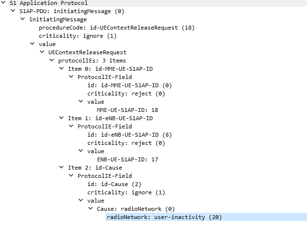
In order to keep radio resources free, if a UE doesn’t send or receive data for a predefined threshold, it’ll detach from the network and call back to Idle mode.
If the UE has data to send to the network, the UE will re-attach to the network, whereas if the network has data to send to the UE, it’ll Page the UE in the tracking area it’s currently in, the UE is always listening for it’s identifier (s-TMSI) on the paging channel, and if it hears it’s identifier called, the UE will re-attach.
I’ve also attached a PCAP file of the packet flow between the eNB and the MME.
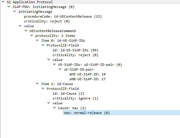
The next packet is sent from the MME back to the eNB confirming UE is releasing from the network.
UEContextReleaseCommand
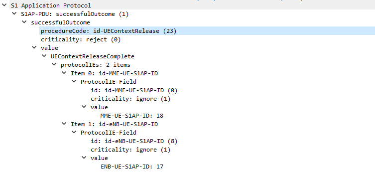
UEContextReleaseComplete
Finally after the UE has released it’s radio resources the eNB sends a UEContextReleaseComplete so the MME knows the UE is now in Idle state and will need to be paged.
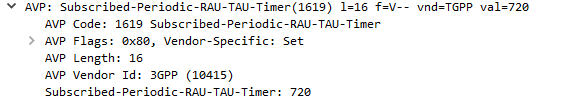
Recently we saw Open5Gs’s Update Location Answer response putting the Subscribed-Periodic-RAU-TAU-Timer AVP in the top level and not in the AVP Code 1400 (APN Configuration) Diameter payload from the HSS to the MME.
But what exactly does the Subscribed-Periodic-RAU-TAU-Timer AVP in the Update Location Answer response do?
Folks familiar with EUTRAN might recognise TAU as Tracking Area Update, while RAU is Routing Area Update in GERAN/UTRAN (UMTS).
Periodic tracking area updating is used to periodically notify the availability of the UE to the network. The procedure is controlled in the UE by the periodic tracking area update timer (timer T3412). The value of timer T3412 is sent by the network to the UE in the ATTACH ACCEPT message and can be sent in the TRACKING AREA UPDATE ACCEPT message. The UE shall apply this value in all tracking areas of the list of tracking areas assigned to the UE, until a new value is received.
Section 5.3.5 of 24301-9b0 (3GPP TS 24.301 V9.11.0)
So the Periodic Tracking Area Update timer simply defines how often the UE should send a Tracking Area Update when stationary (not moving between cells / tracking area lists).
On a PCM (G.711) RTP packet the payload is typically 160 bytes per packet.
But the total size of the frame on the wire is typically ~214 bytes, to carry a 160 byte payload that means 25% of the data being carried is headers.
This is fine for VoIP services operating over fixed lines, but when we’re talking about VoLTE / IMS and the traffic is being transferred over Radio Access Networks with limited bandwidth / resources, it’s important to minimize this as much as possible.
IMS uses the AMR codec, where the RTP payload for each packet is around 90 bytes, meaning up to two thirds of the packet on the wire (Or in this case the air / Uu interface) is headers.
Using ROHC the size of the headers are cut down to only 4-5 bytes, this is because the IPv4 headers, UDP headers and RTP headers are typically the same in each packet – with only the RTP Sequence number, RTP timestamp IPv4 & UDP checksum and changing between frames.
I modified the Kamailio config allow Transcoding, as I talked about in the post on setting up Transcoding in RTPengine with Kamailio.
Now I had a working Kamailio instance with RTPengine that was transcoding.
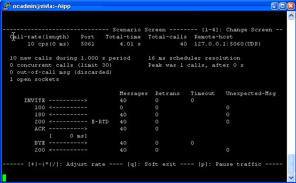
So the next step becomes testing the transcoding is working, for this I had two SIPp instances, one to make the calls and once to answer them.
Instance 1
Makes calls to the IP of the Kamailio / RTPengine instance, for this I modified the uac_pcap scenario to playback an RTP stream of a PCMA (G.711 a-law) call to the called party (stored in a pcap file), and made it call the Kamailio instance multiple times based on how many concurrent transcoding sessions I wanted: