As our subscribers are mobile, moving between base stations / cells, the destination of the incoming GTP-U packets needs to be updated every time the subscriber moves from one cell to another.
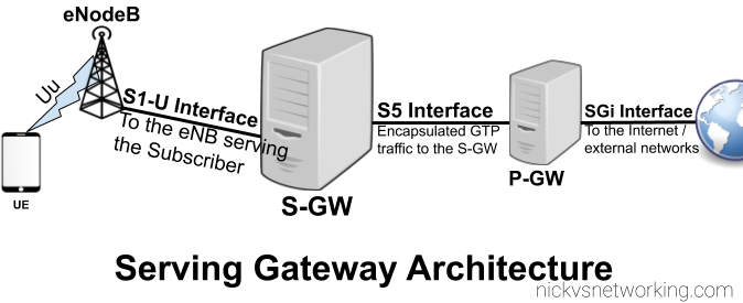
As we covered in the last post, the Packet Gateway (P-GW) handles decapsulating and encapsulating this traffic into GTP from external networks, and vise-versa. The Packet Gateway sends the traffic onto a Serving Gateway, that forwards the GTP-U traffic onto the eNodeB serving the user.
So why not just route the traffic from the Packet Gateway directly to the eNodeB?
As our users are inherently mobile, the signalling load to keep updating the destination of the incoming GTP-U traffic to the correct eNB, would put an immense load on the P-GW. So an intermediary gateway – the Serving Gateway (S-GW), is introduced.
The S-GW handles the mobility between cells, and takes the load of the P-GW. The P-GW just hands the traffic to a S-GW and let’s the S-GW handle the mobility.
It’s worth keeping in mind that most LTE connections are not “always on”. Subscribers (UEs) go into “Idle Mode”, in which the data connection and the radio connection is essentially paused, and able to be bought back at a moments notice (this allows us to get better battery life on the UE and better frequency utilisation).
When a user enters Idle Mode, an incoming packet needs to be buffered until the Subscriber/UE can get paged and come back online. Again this function is handled by the S-GW; buffering packets until the UE comes available then forwarding them on.
A question that seems to come up often, is how to provide a static IPs to UEs on Open5GS EPC.
By default all UEs are allocated an internal IP that the server the P-GW is running on NATs out, but many users want to avoid NAT, for obvious reasons.
Open5GS has the ability to set a Static IP for each APN a subscriber has, but let’s get one thing out of the way first;
LTE is not Ethernet. No broadcast, no multicast. Each IP Address is best thought of as a single /32 network. This means you can’t have the UEs in your LTE network in the same 192.168.1.x subnet as your home network along with your laptop and printer, it’s not how it works.
So with that out of the way, let’s talk about how to do static IP address allocation in Open5GS EPC.
Assigning a Subscriber a Static IP Address
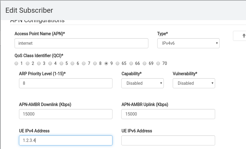
From the HSS edit the Subscriber and in the UE IPv4 or UE IPv6 address, set the static address you want to use.
You can set any UE IP Address here and it’ll get allocated to that UE.
But – there’s an issue.
The problem is not so much on the Open5GS P-GW implementation, but just how TCP/IP routing works in general.
Let’s say I assign the UE IPv4 address 1.2.3.4 to my UE. From the UE it sends a packet with the IPv4 Source address of 1.2.3.4 to anywhere on the internet, the eNB puts the packet in GTP and eventually the it gets to the P-GW which sends it out onto the internet from the source address 1.2.3.4.
The problem is that the response will never get back to me, as 1.2.3.4 is not allocated to me and will never make it back to my P-GW, so never relayed back to the UE.
For TCP traffic this means I can send the SYN with the source address of 1.2.3.4, but the SYN/ACK will be routed back to the real 1.2.3.4, and not to me, so the TCP socket will never get opened.
So while we can set a static IPs to be allocated to UEs in Open5GS, unless the traffic can be routed back to these IPs it’s not much use.
Routing
So let’s say we have assigned IP 1.2.3.4 to the UE, we’d need to put a static route on our routers to route traffic to the IP of the PGW. In my case the PGW is 10.0.1.121, so I’ll need to add a static route to get traffic destined 1.2.3.4/32 to 10.0.1.121.
In a more common case we’d assign internal IP subnets for the UE pool, and then add routes for the entire subnet to the IP of the PGW.
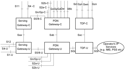
3GPP release 14 introduced the concept of CUPS – Control & User Plane Separation, and the Sx interface, this allows the control plane (GTP-C) functionality and the user plane (GTP-U) functionality to be separated, and run in a distributed fashion, allowing the node a user’s GTP-U traffic flows through to be in a different location to where the Control / Signalling traffic (GTP-C) flows.
In practice that means for an LTE EPC this means we split our P-GW and S-GW into a minimum of two network elements each.
A P-GW is split and becomes a P-GW-C that handles the P-GW Control Plane traffic (GTPv2-C) and a P-GW-U speaking GTP-U for our User Plane traffic. But the split doesn’t need to stop there, one P-GW-C could control multiple P-GW-Us, routing the user plane traffic. Sames goes for S-GW being split into S-GW-C and S-GW-U,
This would mean we could have a P-GW-U located closer to a eNB / User to reduce latency, by allowing GTP-U traffic to break out on a node closer to the user.
It also means we can scale better too, if we need to handle more data traffic, but not necessarily more control plane traffic, we can just add more P-GW-U nodes to handle this.
To manage this a new protocol was defined – PFCP – the Packet Forwarding Control Protocol. For LTE this is refereed to as the Sx reference point, it’ also reused in 5G-SA as the N4 reference point.
When a GTP-C “Create Session Request” comes into a P-GW for example from an S-GW, a PFCP “Session Establishment Request” is sent by the P-GW-C to the P-GW-U with much the same information that was in the GTP-C request, to setup the session.
So why split the Control and User Plane traffic if you’re going to just relay the GTP-C traffic in a different format?
That was my first question – the answer is that keeping the GTP-C interface ensures backward compatibility with older MMEs, PCRFs, charging systems, and allows a staged roll out and bolting on extra capacity.
GTP-C disappears entirely in 5G Standalone architecture and is replaced with the N4 interface, which uses PFCP for the Control Plan and GTP-U again.
Here’s a capture from Open5Gs core showing GTPv2C and PFCP in play.
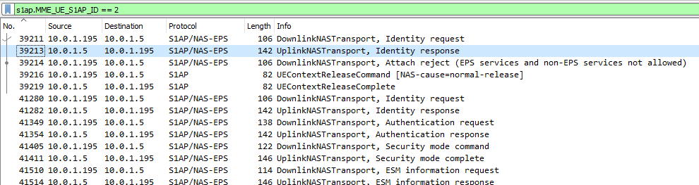
The S1 interface can be pretty noisy, which makes it hard to find the info you’re looking for.
So how do we find all the packets relating to a single subscriber / IMSI amidst a sea of S1 packets?
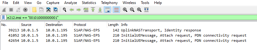
The S1 interface only contains the IMSI in certain NAS messages, so the first step in tracing a subscriber is to find the initial attach request from that subscriber containing the IMSI.
Luckily we can filter in Wireshark to find the IMSI we’re after;
Quick note – Not all IntialUEMessages will contain the IMSI – If the subscriber has already established comms with the MME it’ll instead be using a temporary identifier – M-TMSI, unless you’ve got a way to see the M-TMSI -> IMSI mapping on the MME you’ll be out of luck.
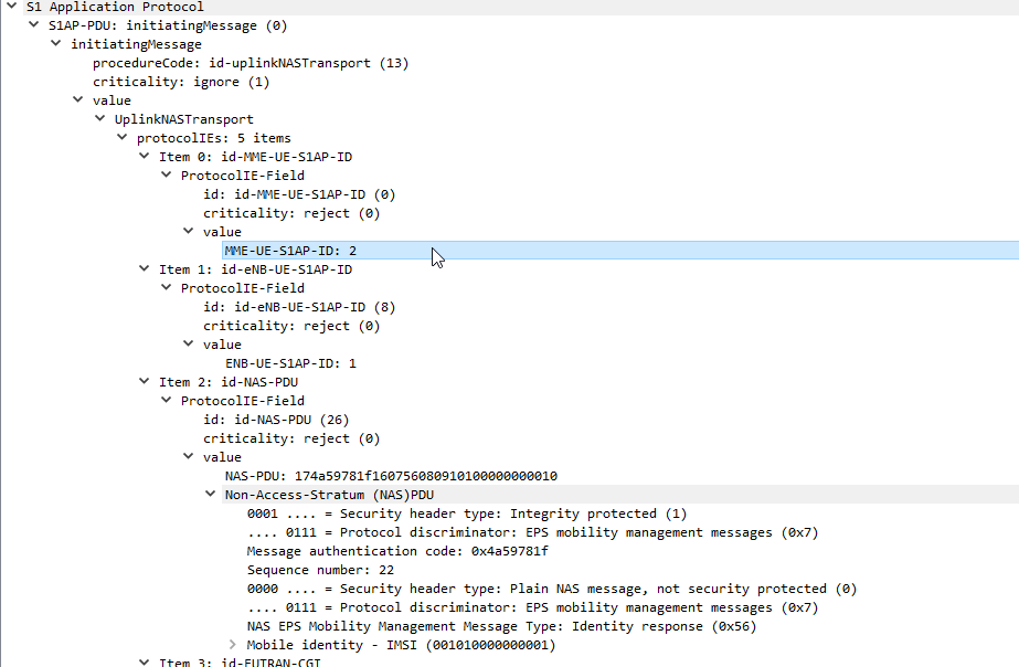
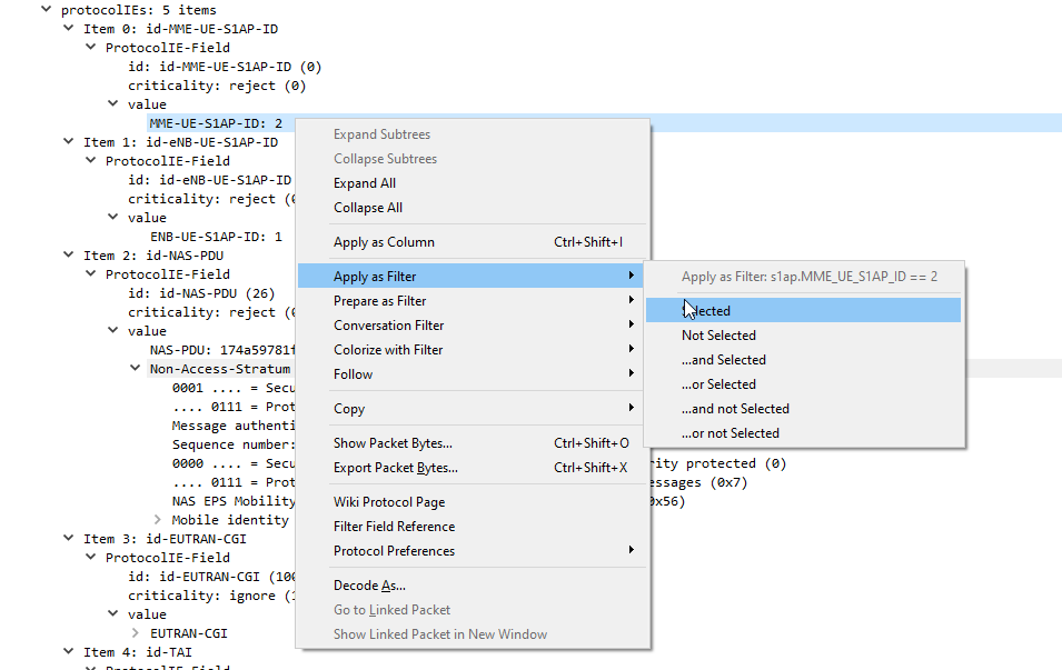
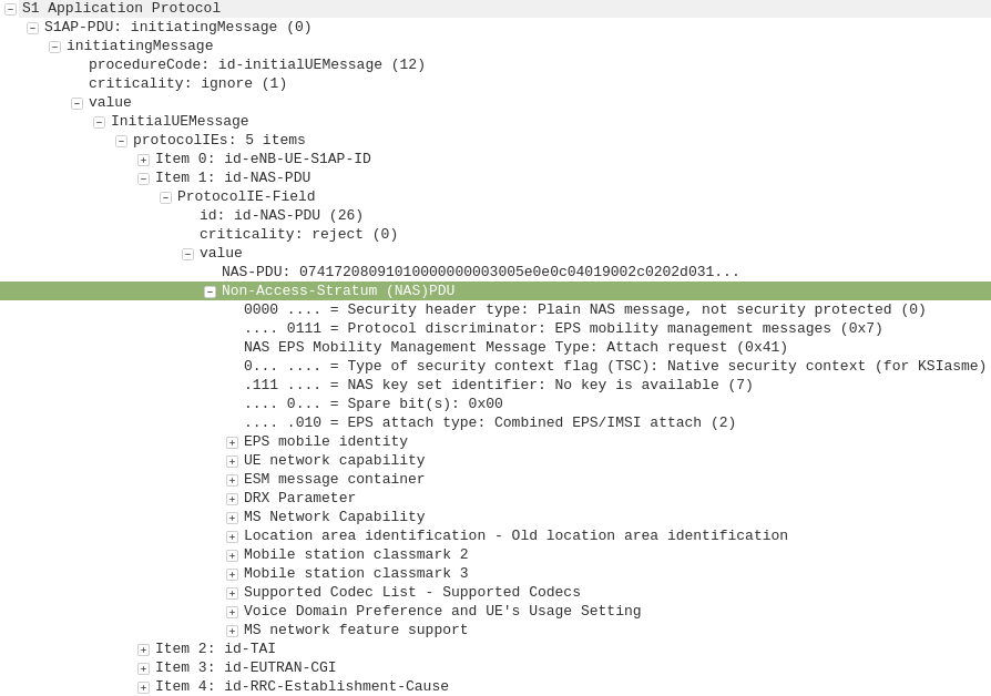
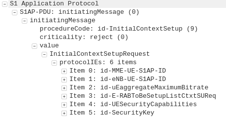
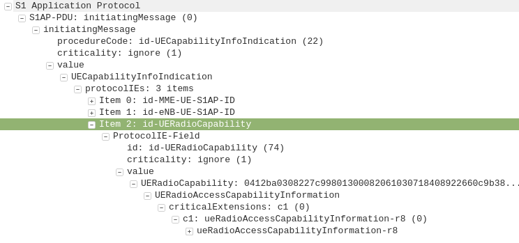
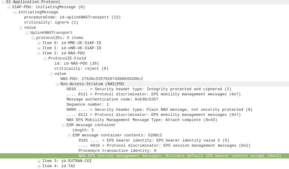
Next up let’s take a look at the contents of one of these packets,
Inside the protocolIEs is the MME_UE_S1AP_ID – This unique identifier will identify all S1 signalling for a single user.
The MME_UE_S1AP_ID is a unique identifier, assigned by the MME to identify which signaling messages are for which subscriber.
(It’s worth noting the MME_UE_S1AP_ID is only unique to the MME – If you’ve got multiple MMEs the same MME_UE_S1AP_ID could be assigned by each).
So now we have the MME_UE_S1AP_ID, we can filter all S1 messaging containing that MME_UE_S1AP_ID, we’ll use this Wireshark filter to get it:
s1ap.MME_UE_S1AP_ID == 2
Boom, there’s a all the signalling for that subscriber.
Alternatively you can just right click on the value and apply it as a filter instead of typing everything in,
Hopefully that’ll help you filter to find what you’re looking for!
So a problem had arisen, carriers wanted to change certain carrier related settings on devices (Specifically the Carrier Config Manager) in the Android ecosystem. The Android maintainers didn’t want to open the permissions to change these settings to everyone, only the carrier providing service to that device.
And if you purchased a phone from Carrier A, and moved to Carrier B, how do you manage the permissions for Carrier B’s app and then restrict Carrier A’s app?
The carrier loads a certificate onto the SIM Cards, and signing Android Apps with this certificate, allowing the Android OS to verify the certificate on the card and the App are known to each other, and thus the carrier issuing the SIM card also issued the app, and presto, the permissions are granted to the app.
Carriers have full control of the UICC, so this mechanism provides a secure and flexible way to manage apps from the mobile network operator (MNO) hosted on generic app distribution channels (such as Google Play) while retaining special privileges on devices and without the need to sign apps with the per-device platform certificate or preinstall as a system app.
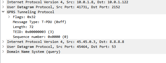
If you’re using an GSM / GPRS, UMTS, LTE or NR network, there’s a good chance all your data to and from the terminal is encapsulated in GTP.
GTP encapsulates user’s data into a GTP PDU / packet that can be redirected easily. This means as users of the network roam around from one part of the network to another, the destination IP of the GTP tunnel just needs to be updated, but the user’s IP address doesn’t change for the duration of their session as the user’s data is in the GTP payload.
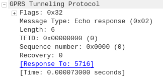
One thing that’s a bit confusing is the TEID – Tunnel Endpoint Identifier.
Each tunnel has a sender TEID and transmitter TEID pair, as setup in the Create Session Request / Create Session Response, but in our GTP packet we only see one TEID.
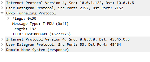
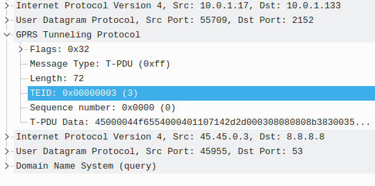
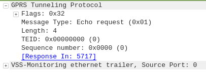
There’s not much to a GTP-U header; at 8 bytes in all it’s pretty lightweight. Flags, message type and length are all pretty self explanatory. There’s an optional sequence number, the TEID value and the payload itself.
So the TEID identifies the tunnel, but it’s worth keeping in mind that the TEID only identifies a data flow from one Network Element to another, for example eNB to S-GW would have one TEID, while S-GW to P-GW would have another TEID.
Each tunnel has two TEIDs, a sending TEID and a receiving TEID. For some reason (Minimize overhead on backhaul maybe?) only the sender TEID is included in the GTP header;
This means a packet that’s coming from a mobile / UE will have one TEID, while a packet that’s going to the same mobile / UE will have a different TEID.
Mapping out TIEDs is typically done by looking at the Create Session Request / Responses, the Create Session Request will have one TIED, while the Create Session Response will have a different TIED, thus giving you your TIED pair.
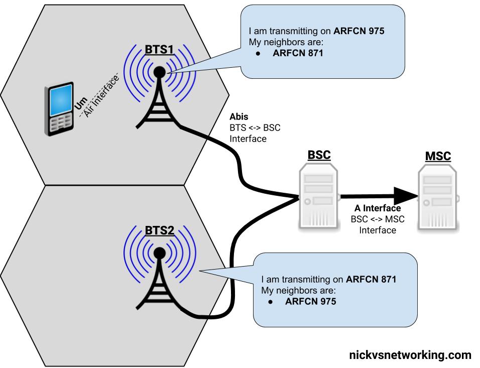
With just one cell/BTS, your mobile phone isn’t all that mobile.
So GSM has the concept of handovers – Once BTS (cell) can handover a call to another cell (BTS), thus allowing us to move between BTSs and keep talking on a call.
Note: I’ll use the term BTS here, because we’ve talked a lot about BTSs throughout this series. Technically a BTS can be made up of one or more cells, but to keep the language consistent with the rest of the posts I’ll use BTS, even though were talking about the cell of a BTS.
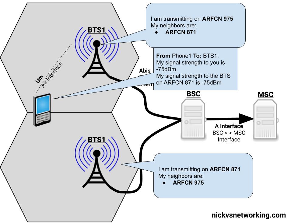
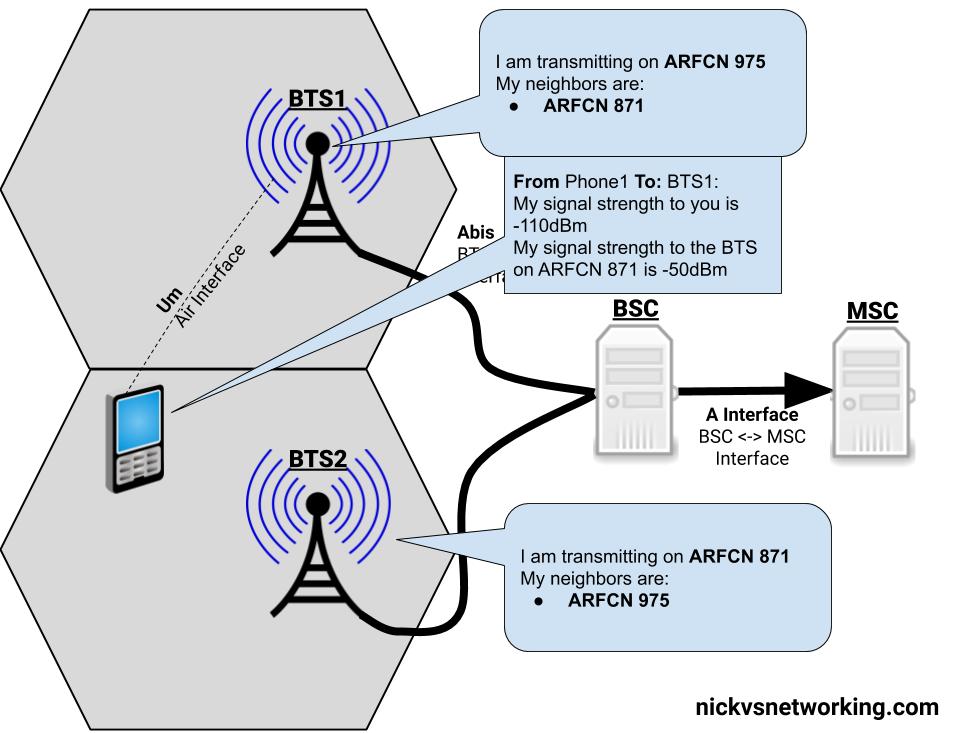
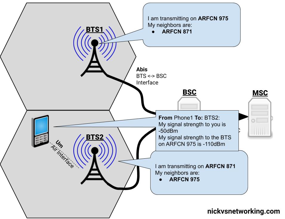
If we’re on a call, in an area served by BTS1, and we’re moving towards BTS2, at some point the signal strength from BTS2 will surpass the signal strength from BTS1, and the phone will be handed over from BTS1 to BTS2.
Handovers typically only occur when a channel is in use (ie on a phone call) if a phone isn’t in use, there’s no need to seamlessly handover as a brief loss of connectivity isn’t going to be noticed by the users.
Measurements
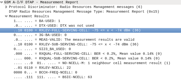
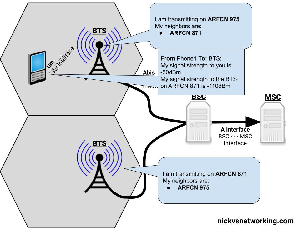
The question as to when to handover a call to a neighbouring cell, comes down to the signal strength levels the phone is experiencing.
The phone measures the signal strength of up to 6 nearby (neighbouring) BTSs, and reports what signal strength it’s receiving to the BTS that’s currently serving it.
The BTS then sends this info to the BSC, in the RXLEV fields of a RSL Measurement Report packet.
RXLEV fields of a RSL Measurement Report packet.
With this information the BSC makes the determination of when to handover the call to a neighbouring BTS.
There’s a lot of parameters that the BSC takes into account when making the decision to handover to a neighbouring BTS, but for the purposes of this explanation, we’ll simplify this and just imagine it’s based on which BTS has the strongest signal strength as seen by the phone.
Everybody needs good Neighbors
Our phone can only monitor the signal strength of so many neighboring cells at once (Up to 6). So in order to know which frequency (known as ARFCNs) to take signal strength measurements on, our phone needs to know the frequencies it should expect to see neighbours, so it can measure these frequencies.
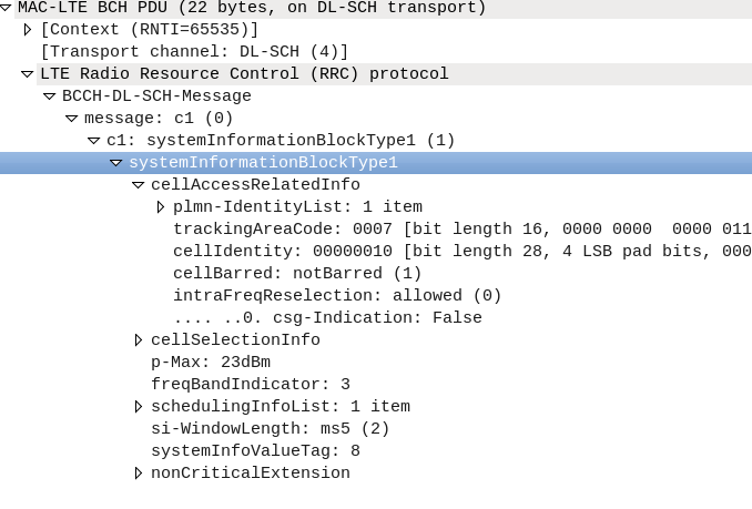
The System Information Block 2 is broadcast by the BTS on the BCCH and SACCH channels, and contains the ARFCNs (Frequencies) of the BTSs that neighbour that cell.
With this info our Phone only needs to monitor the frequencies (ARFCNs) of the cells nearby it’s been told about in the SIB2 to check the received power levels on those frequences.
The Handover
This is vastly simplified…
So our phone is armed with the list of neighbouring cell frequencies (ARFCNs) and it’s taking signal strength measurements and sending them to the BTS, and onto the BSC. The BSC knows the strength of the signals around our phone on a call.
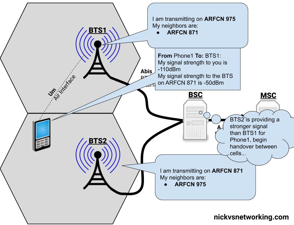
With this information the BSC makes the decision that the serving cell (BTS) the phone is currently connected to is no longer the best candidate, as another BTS would provide a higher signal strength and begins a handover to a neighbouring BTS with a better signal to the phone.
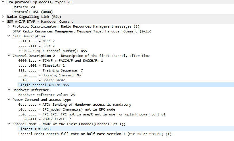
Our BSC starts by giving the new BTS a heads up it’s going to hand a call of to it, by setting up the channel to use on the new BTS, through a Channel Activation message.
Next a handover command is sent to the phone via the BTS it was initially connected to (RSL Handover Command), telling the phone to begin handover to the new BTS and the channel it should move to on the new BTS it setup earier.
Screenshot of a packet capture showing a GSM Handover
The phone moves to the new BTS, and is acknowledged by the phone. The channels the phone was using on the old BTS are released and the handover is complete.
Simplified Diagram of the Process
There is a lot more to handovers than just this, which we’ll cover in a future post.
This is part of a series of posts focusing on common Diameter request pairs, looking at what’s inside and what they do.
The Authentication Information Request (AIR) and Authentication Information Answer (AIA) are one of the first steps in authenticating a subscriber, and a very common Diameter transaction.
The Process
The Authentication Information Request (AIR) is sent by the MME to the HSS to request when a Subscriber begins to attach containing the IMSI of the subscriber trying to connect.
If the subscriber’s IMSI is known to the HSS, the AuC will generate Authentication Vectors for the Subscriber, and repond back to the MME in an Authentication Information Answer (AIA).
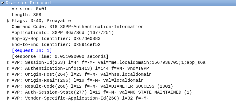
The AIR is a comparatively simple request, without many AVPs;
The Session-Id, Auth-Session-State, Origin-Host, Origin-Realm & Destination-Realm are all common AVPs that have to be included.
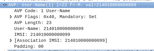
The Username AVP (AVP 1) contains the username of the subscriber, which in this case is the IMSI.
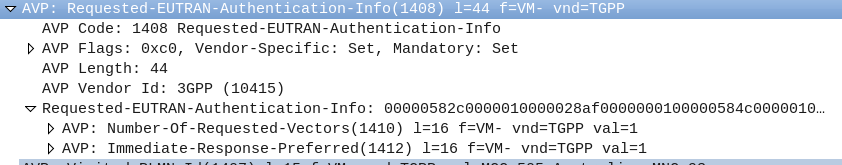
The Requested-EUTRAN-Authentication-Info AVP ( AVP 1408 ) contains information in regards to what authentication info the MME is requesting from the subscriber, typically this indicates the MME is requesting 1 vector (Number-Of-Requested-Vectors (AVP 1410)), an immediate response is preferred (Immediate-Response-Preferred (AVP 1412)), and if the subscriber is re-resyncing the SQN will include a Re-Synchronization-Info AVP (AVP 1411).
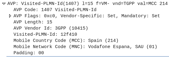
The Visited-PLMN-Id AVP (AVP 1407) contains information regarding the PLMN of the RAN the Subscriber is connecting to.
The Authentication Information Answer (AIA)
The Authentication Information Answer contains several mandatory AVPs that would be expected, The Session-Id, Auth-Session-State, Origin-Host and Origin-Realm.
The Result Code (AVP 268) indicates if the request was successful or not, 2001 indicates DIAMETER SUCCESS.
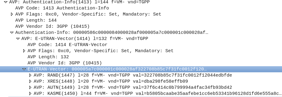
The Authentication-Info (AVP 1413) contains the returned vectors, in LTE typically only one vector is returned, a sub AVP called E-UTRAN-Vector (AVP 1414), which contains AVPs with the RAND, XRES, AUTN and KASME keys.
When setting up the timeslots on the TRX for each BTS on your BSC, you’ll notice you have to set a channel type.
So what do these acronyms mean, and how do they affect the performance of the network?
GSM channels break down into one of to categories, control channels – used for signalling, and traffic channels, used for carrying information to/from a user.
A network with only control channels wouldn’t allow a call to be made, as there would be no traffic channels to carry the audio of the call,
Conversely a network with only traffic channels would have plenty of capacity for calls, but without a control channel would have no way of setting them up.
Traffic Channels
Traffic channels break down into a further two categories, voice channels for carrying call audio, and data channels for carrying GPRS data.
Traffic Channels for Voice
There’s a few variants of voice channel based on the codec used for encoding the voice data, the more compressed / small the audio signal is, the more you can cram in per channel, at the sacrifice of voice quality.
Common options are Traffic Channel – Full Rate (TCH/F), & Traffic Channel – Half Rate (TCH/F) channels.
Traffic Channels for Data
When GPRS was introduced it needed to be transported on a traffic channel, but unlike a voice channel, the resources weren’t going to be used 100% of the time (like in a voice call) and could be shared on an as-needed basis.
Data channels are also also broken down into full rate and half rate channels, like Traffic Channel – Full Rate (TCH/F), & Traffic Channel – Half Rate (TCH/F) channels.
Control Channels
Control channels carry the out of band signalling between the Phone and the BTS.
Broadcast Channels
Broadcast Channels are by their very nature – Broadcasted, this means every phone on the BTS gets these messages.
There are 3 broadcast channels, the FCCH for frequency corrections, SCH for synchronisation and BCCH for a common channel that transmits information to all phones, containing info on the network such as the PLMN, neighbouring cells, etc.
Common Channels
The PCH – Paging Channel, is used to page phones in idle mode. All phones will listen on the paging channel, and if they hear their identifier will establish a connection back to the network.
RACH the Random Access Control Channel is used for when the phone wants to establish a connection with the network, by picking a random timeslot to transmit it’s data on the RACH.
The ACGC is the Access Grant Channel, containing information about dedicated channels to be assigned to phones.
Dedicated Control Channels
Like dedicated traffic channels, dedicated channels are only in use by one phone at a time.
The SDCCH is the standalone dedicated control channel, over which location updates, SMS, authentication & call setup / teardown signalling is transferred.
The SACCH – slow Associated Control Channel is used for timing advance (when users are further from the BTS timing advances are needed to ensure propogation time is taken into account), power control information, signaling data and radio measurements.
Finally the FACCH – Fast Associated Control is used for transferring larger messages such as for handover information,
Depending on if you’re wearing a tin foil hat or not, silent SMS and silent calls could be a useful tool to for administering the network or a backdoor put in to track citizenry!
Regardless of it’s reasons for existence, let’s take a look at what it actually does, and how we can use it.
To conserve battery and radio resources, terminals / UEs go into an idle state where they monitor the RSSI of the BTS/NodeB and the broadcast/paging channels, but don’t actively send anything on the uplink.
Let’s say we wanted to get the RSSI measurements from a terminal/UE we would need the terminal to go into an active state.
We could do this by calling the terminal, or sending an SMS, but if we wanted to do it without alerting the user, that’s when we can use Silent SMS and silent calls, to do so without alerting the user.
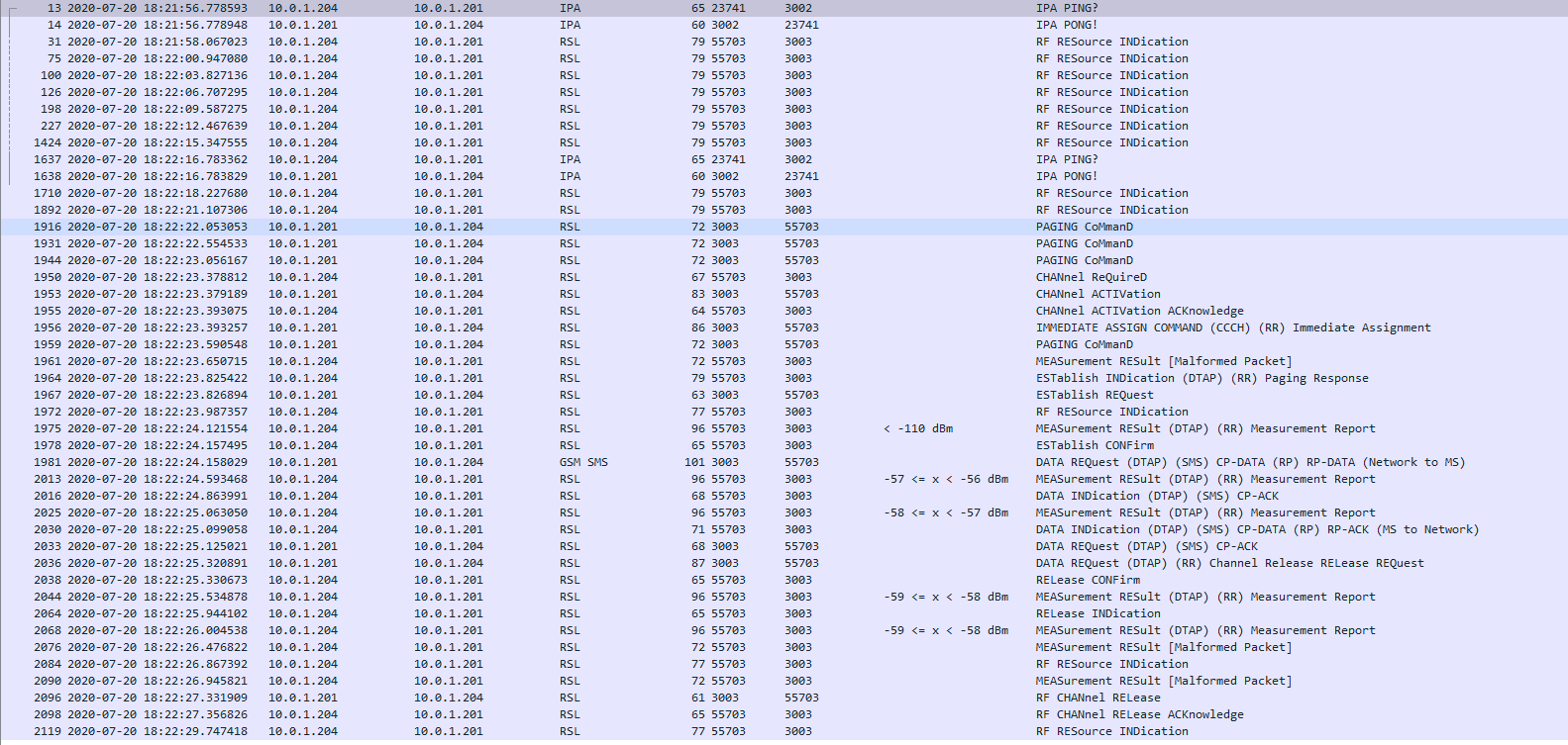
If you want to try this you can send a Silent SMS from Osmo-MSC.
Packet capture shows no traffic on the Abis interface until the Silent SMS is sent
On top of Silent SMS there’s also silent calls, allowing for a continued stream of measurements from the UE, which can also be super useful for creating a single call leg.
Another use for Silent SMS it to interface with the SIM Card, many card manufacturers provide support for “over the air” updating of the SIM Card parameters (think if MNO A purchases MNO B and they want to share a network, you don’t want to have to re-issue every SIM card with the updated PLMN, just update the parameters on the SIM).
Messages from the network operator to their SIM cards don’t need to be shown to the user, so are can be carried via Silent SMS. – SIM card manufacturers don’t make the nitty gritty details of this functionality public – it’s a proprietary interface defined by the manufacturer, simply transported by SMS.
In the S1-SETUP-RESPONSE and MME-CONFIGURATION-UPDATE there’s a RelativeMMECapacity (87) IE,
So what does it do?
Most eNBs support connections to multiple MMEs, for redundancy and scalability.
By returning a value from 0 to 255 the MME is able to indicate it’s available capacity to the eNB.
The eNB uses this information to determine which MME to dispatch to, for example:
MME Pool
Relative Capacity
mme001.example.com
20/255
mme002.example.com
230/255
Example MME Pooling table
The eNB with the table above would likely dispatch any incoming traffic to MME002 as MME001 has very little at capacity.
If the capacity was at 1/255 then the MME would very rarely be used.
The exact mechanism for how the MME sets it’s relative capacity is up to the MME implementer, and may vary from MME to MME, but many MMEs support setting a base capacity (for example a less powerful MME you may want to set the relative capacity to make it look more utilised).
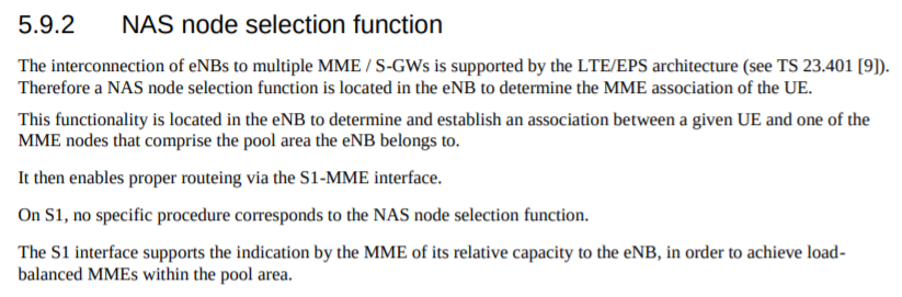
I looked to 3GPP to find what the spec says:
On S1, no specific procedure corresponds to the NAS node selection function. The S1 interface supports the indication by the MME of its relative capacity to the eNB, in order to achieve loadbalanced MMEs within the pool area.
3GPP TS 36.410 – 5.9.2 NAS node selection function
I’ve been experimenting with Inter-RAT & Inter-Frequency handovers recetly, and had an issue where what I thought was configured on the eNB I wasn’t seeing reflected on the UEs.
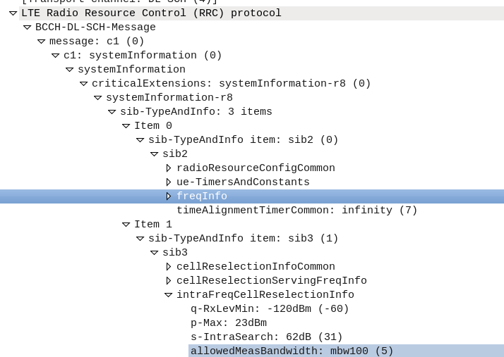
I understood the Neighbouring Cell reelection parameters are broadcast in the System Information Blocks, but how could I view them?
The answer – srsUE!
I can’t get over how cool the stuff coming out of Software Radio Systems is, but being able to simulate a UE and eNB on SDR hardware is pretty awesome, and also allows you to view low layer traces the vast majority of commercial UEs will never expose to a user.
After running srsUE with the PCAP option I let it scan for networks and find mine. I didn’t actually need to authenticate with the network, just lock to the cell.
So far we’ve focused on building a plain “2G” (voice and SMS only) network, which was all consumers expected twenty years ago.
As the number of users accessing the internet through DSL, Dial Up & ISDN grew, the idea of getting this data “on the go” became more appealing. TCP/IP was becoming the dominant standard for networking, the first 802.11 WiFi spec had recently been published and demand for mobile data was growing.
There’s a catch however – TCP/IP was never designed to be mobile.
An IP address exists in a single location.
(Disclaimer: While you can “move” a subnet by advertising itself out in a different location via BGP peering relationships with other operators, it’s cumbersome, can only be done per /24 or larger, and most importantly it’s painfully slow. IPv6 has MIPv6 which attempts to fix some of these points, but that’s outside of this scope.)
GPRS addressed the mobility issue by having a single fixed point the IP Address is assigned to (the Gateway GPRS Support Node), which encapsulates IP traffic to/from a mobile user into GTP Packet (GPRS Tunnelling Protocol), like GRE or any of the other common routing encapsulation protocols, allowing the traffic to be rerouted to different destinations as the users move from being served by one BTS to another BTS.
So now we’ve got a method of encapsulating our data we’ve got to work out how to get that data out over the air.
BTS Time Slots
Way back when we were first setting up our BSC and adding our BTS(s) you will have configured timeslots for each BTS configured on your BSC.
Chances are if you’ve been following along with this tutorial, that you configured the first time slot (timeslot 0) as a CCCH+SDCCH4, meaning Common Control Channel and 4 standalone dedicated control channels, and all the subsequent timeslots (timeslot 1 – 7) as Traffic Channels (full rate) – TCH/F.
This works well if we’re only carrying voice, but to carry data we need timeslots to put the data traffic on.
For this we’ll re assign a timeslot we were using on our BSC as a voice traffic channel (TCH/F) as a PDCH – a Packet Data Channel.
This means that on the BSC your timeslot config will look something like this:
In the above example I’ve assigned two timeslots for Packet Data Channels,
The more timeslots you allocate for data, the more bandwidth available, but the fewer voice resources available.
(Most GSM networks today have few data timeslots as more recent RATs like 3G/4G are taking the data traffic, and GSM is used primarily for voice and low bandwidth M2M communications)
GPRS and EDGE
GPRS comes in two flavors, GPRS and EDGE.
GPRS (General Packet Radio Services) was the first of the two, standardised in R97, and allowed users to reach a downlink speeds of up to 171Kbps using GMSK on the air interface to encode the data.
Users quickly expected more speed, so EDGE (Enhanced Data rates for Global Evolution) was standardised, from a core perspective it was the same, but from a BTS / Air interface perspective it relied on 8PSK instead of GMSK allowed users to reach a blistering 384Kbps on the downlink.
These speeds are the theoretical maximums.
As the difference between GPRS and EDGE is encoding on the air interface, from a core perspective it’s treated the same way, however as our BTS gets all it’s brains from the BSC, we’ll need to specify if the BTS should use EDGE or GPRS it in the BSC’s BTS config.
BSC Config
On the BSC for each BTS we want to enable for packet data, we’ll need to define the parameters.
There’s two other values we’ll introduce when setting this up,
The first is NSEI – the Network Service Entity Identifier, which is the identifier of the BTS’s Packet Control Unit, like the cell identity.
The second value we’ll touch on is the BVCI – the BSSGP Virtual Connections Identifier, which is used for addressing between the BTS PCU and the SGSN.
SS7 was first introduced in the 1970s and initially was designed for large scale setting up and tearing down of calls, but due to it’s layered architecture and prominence in the industry has been used for signalling between some CS network elements in Mobile Networks, including transporting messages between the MSC and any BSCs or RNCs it’s serving.
This is going to be fairly brief and Osmocom specific, keep in mind SS7 is a giant topic so there’s a huge amount we won’t cover.
Point Codes – SS7 Addressing & Routing
Historically SS7 networks were carried over TDM links of various types, and not over TCP/IP.
A point code is a unique address associated with each network element for addressing messages between network elements, it’s function is similar to that of an IP Address you’d use in IP networks.
When STP messaging is sent it includes a Source Point Code (SPC) and Destination Point Code (DPC).
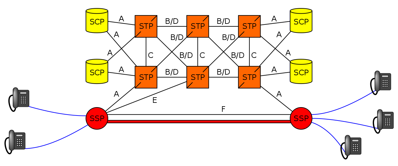
The Signalling Transfer Point
Instead of a one-to-one connection between each SS7 device and every other SS7 device, a network element called a Signaling Transfer Point (STP) is used, which acts somewhat like a router.
The STP has an internal routing table made up of the Point Codes it has connections to and some logic to know how to get to each of them.
When it receives an SS7 message, the STP looks at the Destination point code, and finds if it has a path to that point code. If it does, it forwards the SS7 message on to the destination.
Like a router, an STP doesn’t really concern itself with the upper layer protocols and what they contain – As point codes are set in the MTP3 layer that’s the only layer the STP looks at and the upper layers aren’t really “any of its business”.
Sigtran & SS7 Over IP
As the world moved towards IP enabled everything, TDM based Sigtran Networks became increasingly expensive to maintain and operate, so a IETF taskforce called SIGTRAN was created to look at moving SS7 traffic to IP.
The first layer of SS7 were dropped it primarily concerned the physical side of the network, and in the Osmocom implementation the MTP3 layer and up were put into SCTP packets and carried on the network.
Notice I said SCTP and not TCP or UDP? I’ve touched upon SCTP on this blog before, it’s as if you took the best bits of TCP without the issues like head of line blocking and added multi-homing of connections.
To establish an SS7 connection over IP the MTP3 message an SCTP socket is established from the device to the STP, and then an ASP Maintenance message is sent, followed by a Registration Request containing it’s point code, and presto, we have a connection.
The Osmo STP
The Osmocom STP acts in a very trusting manner by default,
When a device wants to connect to the STP it does so via a REG_REQ (Registration Request) containing it’s Point Code. The STP accepts the connection with a REG_RSP (Registration Response).
For as long as that connection stays up any SS7 messages destined to that point code of the device that just registered, the STP will now how to get it there.
Assuming you’ve already installed the OsmoSTP you can access it on 4239:
root@gsm-bts:/etc/osmocom# telnet localhost 4239
Trying 127.0.0.1…
Connected to localhost.
Welcome to the OsmoSTP VTY interface
OsmoSTP>
After running enable we can check the current routing table:
OsmoSTP# show cs7 instance 0 sccp users
SS7 instance 0 has no SCCP
OsmoSTP# show cs7 instance 0 ro
OsmoSTP# show cs7 instance 0 route
Routing table = system
C=Cong Q=QoS P=Prio
Destination C Q P Linkset Name Linkset Non-adj Route

0.23.1/14 0 as-rkm-1 ? ? ?
0.23.3/14 0 as-rkm-2 ? ? ?

OsmoSTP# show cs7 instance 0 as all
Routing Routing Key Cic Cic Traffic
AS Name State Context Dpc Si Opc Ssn Min Max Mode

as-rkm-1 AS_ACTIVE 1 0.23.1 override
as-rkm-2 AS_ACTIVE 2 0.23.3 override

OsmoSTP# show cs7 instance 0 asp
Effect Primary
ASP Name AS Name State Type Remote IP Addr:Rmt Port SCTP
------------ ------------ ------------- ---- ----------------------- ----------
asp-dyn-0 ? ASP_ACTIVE m3ua 127.0.0.1:52192
asp-dyn-1 ? ASP_ACTIVE m3ua 127.0.0.1:33570
Packet Capture
Below is a packet capture showing a connection from an MSC to the STP.
This is a really useful Feature that allows you to break up your S-GW (And by extension P-GW) selection based on geographical areas.
This can be used to enable Local Breakout to a S/P-GW located at the same site as the tower, but controlled by a central MME / HSS.
After updating to the latest version the configuration is pretty straightforard,
P-GW Selection based on eNB ID
# o SGW selection by eNodeB ID (either single enb_id or multiple enb_ids, decimal or hex representation)
#
   selection_mode: enb_id
   gtpc:
     - addr: 127.0.2.3
       enb_id: [9413, 0x98765]
The above config will send any traffic from eNBs with the eNB ID 9413 (encoded as an intiger) or 0x98765 (Encoded as hex int equivilent 624485) to an S-GW at 127.0.2.3.
P-GW Selection based on TAC
# SGW selection by eNodeB TAC (either single TAC or multiple TACs)
#
selection_mode: tac
   gtpc:
     - addr: 127.0.2.2
       tac: [25000, 27000, 28000]
The above config will send any traffic from eNBs with TACs of 25000, 27000, 28000 to an S-GW at 127.0.2.2.
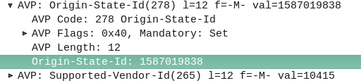
The Origin-State-Id AVP solves a kind of tricky problem – how do you know if a Diameter peer has restarted?
It seems like a simple problem until you think about it. One possible solution would be to add an AVP for “Recently Rebooted”, to be added on the first command queried of it from an endpoint, but what if there are multiple devices connecting to a Diameter endpoint?
The Origin-State AVP is a strikingly simple way to solve this problem. It’s a constantly incrementing counter that resets if the Diameter peer restarts.
If a client receives a Answer/Response where the Origin-State AVP is set to 10, and then the next request it’s set to 11, then the one after that is set to 12, 13, 14, etc, and then a request has the Origin-State AVP set to 5, the client can tell when it’s restarted by the fact 5 is lower than 14, the one before it.
It’s a constantly incrementing counter, that allows Diameter peers to detect if the endpoint has restarted.
Simple but effective.
You can find more about this in RFC3588 – the Diameter Base Protocol.
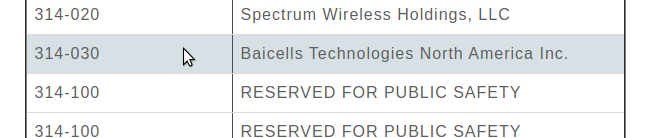
If you’re using BaiCells hardware you may have noticed the new eNBs and USIMs are shipping with the PLMN of MCC 314 / MNC 030.
First thing I do is change the PLMN, but I was curious as to why the change.
It seems 314 / 030 was never assigned to BaiCells to use and when someone picked this up they were forced to change it.
The MCC (Mobile Country Code) part is dictated by the country / geographic area the subscribers’ are in, as defined by ITU, whereas the MNC (Mobile Network Code) allocation is managed by the regional authority and ITU are informed as to what the allocations are and publish in their bulletins.
Well, SIM cards will have a different IMSI / PLMN, but the hardware supports Multi-Operator Core Network which allows one eNB to broadcast multiple PLMNs, so if you update your eNB it can broadcast both!
There’s a lot of layers of signalling in the LTE / EUTRAN attach procedure, but let’s take a look at the UE attach procedure from the Network Perspective.
We won’t touch on the air interface / Uu side of things, just the EPC side of the signaling.
To make life a bit easier I’ve put different signalling messages in different coloured headings:
After a UE establishes a connection with a cell, the first step involved in the attach process is for the UE / subscriber to identify themselves and the network to authenticate them.
The TAI, EUTRAN-CGI and GUMME-ID sections all contain information about the serving network, such the tracking area code, cell global identifier and global MME ID to make up the GUTI.
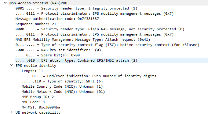
The NAS part of this request contains key information about our UE and it’s capabilities, most importantly it includes the IMSI or TMSI of the subscriber, but also includes important information such as SRVCC support, different bands and RAN technologies it supports, codecs, but most importantly, the identity of the subscriber.
If this is a new subscriber to the network, the IMSI is sent as the subscriber identity, however wherever possible sending the IMSI is avoided, so if the subscriber has connected to the network recently, the M-TMSI is used instead of the IMSI, and the MME has a record of which M-TMSI to IMSI mapping it’s allocated.
Diameter: Authentication Information Request
MME to HSS
The MME does not have a subscriber database or information on the Crypto side of things, instead this functionality is offloaded to the HSS.
I’ve gone on and on about LTE UE/Subscriber authentication, so I won’t go into the details as to how this mechanism works, but the MME will send a Authentication-Information Request via Diameter to the HSS with the Username set to the Subscriber’s IMSI.
Diameter: Authentication Information Response
HSS to MME
Assuming the subscriber exists in the HSS, a Authentication-Information Answer will be sent back from the HSS via Diameter to the MME, containing the authentication vectors to send to the UE / subscriber.
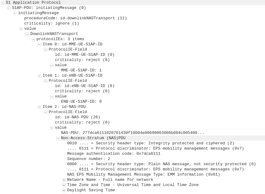
Now the MME has the Authentication vectors for that UE / Subscriber it sends back a DownlinkNASTransport, Authentication response, with the NAS section populated with the RAND and AUTN values generated by the HSS in the Authentication-Information Answer.
The Subscriber / UE’s USIM looks at the AUTN value and RAND to authenticate the network, and then calculates it’s response (RES) from the RAND value to provide a RES to send back to the network.
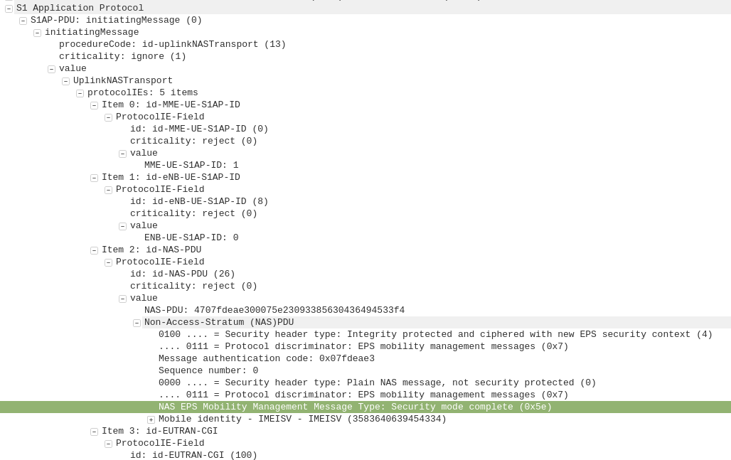
S1AP: UplinkNASTransport, Authentication response
eNB to MME
The subscriber authenticates the network based on the sent values, and if the USIM is happy that the network identity has been verified, it generates a RES (response) value which is sent in the UplinkNASTransport, Authentication response.
The MME compares the RES sent Subscriber / UE’s USIM against the one sent by the MME in the Authentication-Information Answer (the XRES – Expected RES).
If the two match then the subscriber is authenticated.
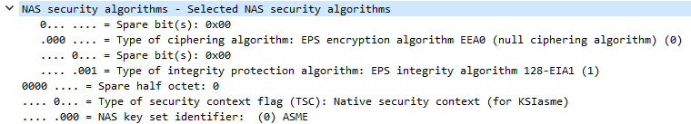
The DownlinkNASTransport, Security mode command is then sent by the MME to the UE to activate the ciphering and integrity protection required by the network, as set in the NAS Security Algorithms section;
The MME and the UE/Subscriber are able to derive the Ciphering Key (CK) and Integrity Key (IK) from the sent crypto variables earlier, and now both know them.
S1AP: UplinkNASTransport, Security mode complete
eNB to MME
After the UE / Subscriber has derived the Ciphering Key (CK) and Integrity Key (IK) from the sent crypto variables earlier, it can put them into place as required by the NAS Security algorithms sent in the Security mode command request.
It indicates this is completed by sending the UplinkNASTransport, Security mode complete.
At this stage the authentication of the subscriber is done, and a default bearer must be established.
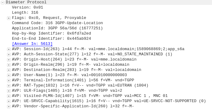
Diameter: Update Location Request
MME to HSS
Once the Security mode has been completed the MME signals to the HSS the Subscriber’s presence on the network and requests their Subscription-Data from the HSS.
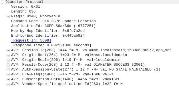
Diameter: Update Location Answer
HSS to MME
The ULA response contains the Subscription Data used to define the data service provided to the subscriber, including the AMBR (Aggregate Maximum Bit Rate), list of valid APNs and TAU Timer.
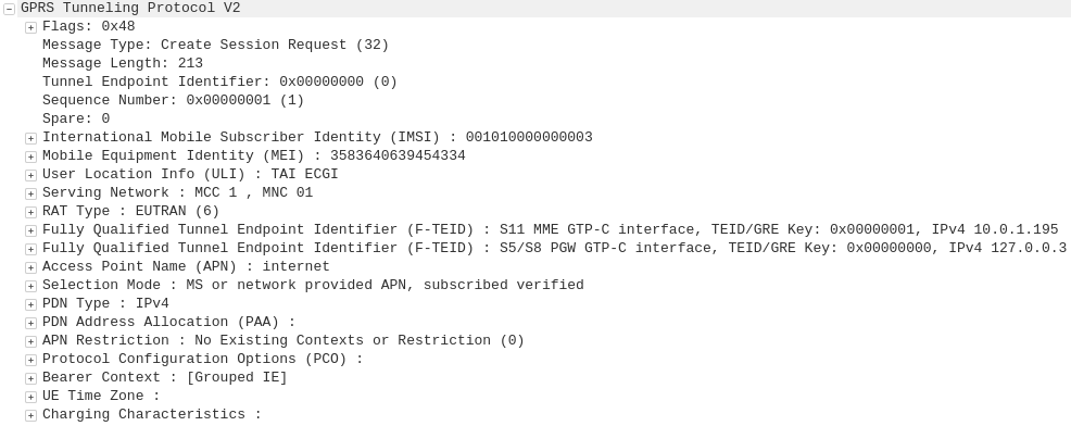
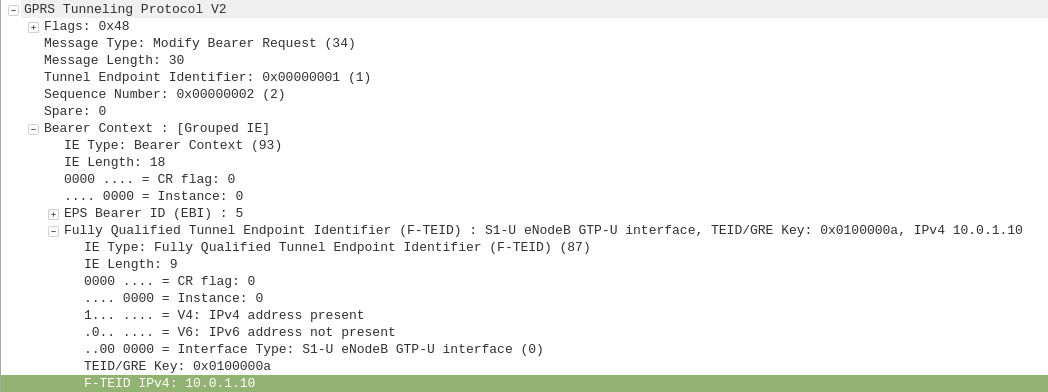
GTP-C: Create Session Request
MME to S-GW
The MME transfers the responsibility of setting up the data bearers to the S-GW in the form of the Create Session Request.
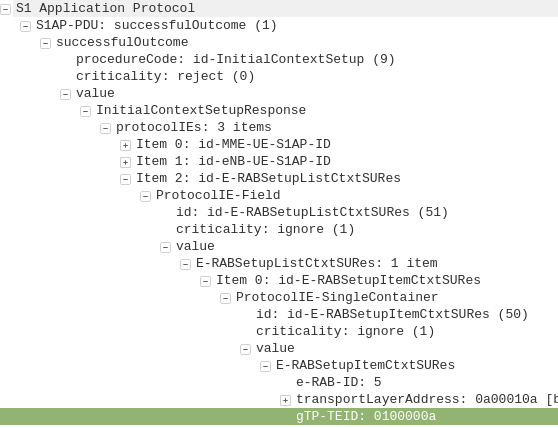
This includes the Tunnel Endpoint Identifier (TEID) to be assigned for this UE’s PDN.
The S-GW looks at the request and forwards it onto a P-GW for IP address assignment and access to the outside world.
GTP-C: Create Session Request
S-GW to P-GW
The S-GW sends a Create Session Request to the P-GW to setup a path to the outside world.
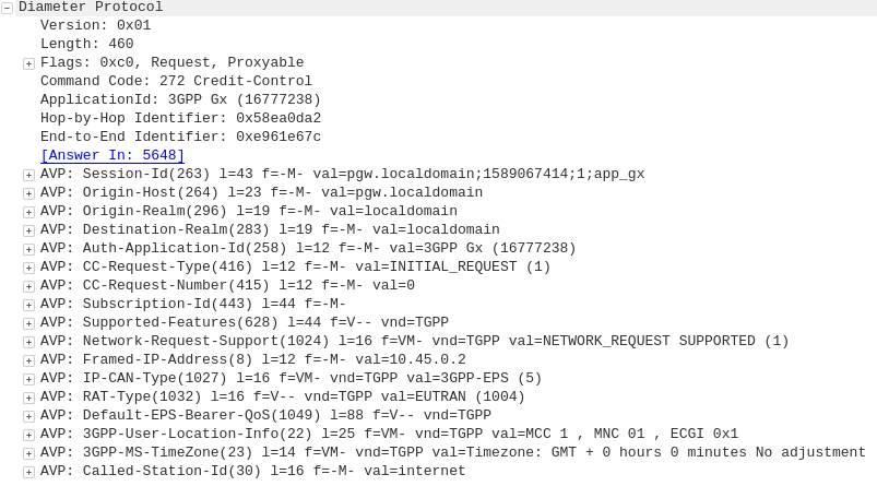
Diameter: Credit Control Request
P-GW to PCRF
To ensure the subscriber is in a state to establish a new PDN connection (not out of credit etc), a Credit Control Request is sent to the HSS.
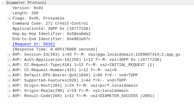
Diameter: Credit Control Answer
PCRF to P-GW
Assuming the Subscriber has adequate credit for this, a Credit Control Answer is sent and the P-GW and continue the PDN setup for the subscriber.
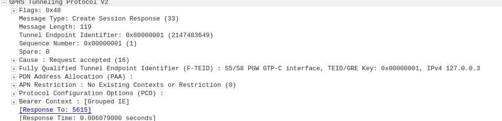
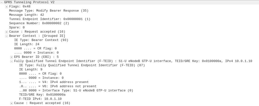
GTP-C: Create Session Response
P-GW to S-GW
The P-GW sends back a Create Session Response, containing the IP address allocated to this PDN (Framed-IP-Address).
GTP-C: Create Session Response
S-GW to MME
The S-GW slightly changes and then relays the Create Session Response back to the MME,
This message is sent to inform the eNB of the details of the PDN connection to be setup, ie AMBR, tracking area list, APN and Protocol Configuration Options,
This contains the Tunnel Endpoint Identifier (TEID) for this PDN to identify the GTP packets.